NATION

PASSWORD

SDI Aircraft Catalog [DO NOT POST]

A meeting place where national storefronts can tout their wares and discuss trade. [In character]

Advertisement

Remove ads

User avatar
The Technocratic Syndicalists
Minister
 
Posts: 2346
Founded: May 27, 2015
Inoffensive Centrist Democracy

Postby The Technocratic Syndicalists » Thu Nov 12, 2020 1:56 pm

Image

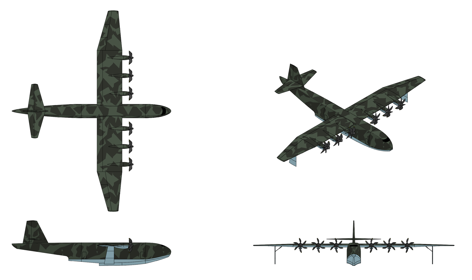
LT 13 Argus

General Characteristics:
  • Role: Aerial refueling tanker and strategic transport aircraft
  • Crew: 3 (pilot, copilot, boom operator)
  • Length: 76.5 m
  • Wingspan: 71.8 m
  • Height: 19.7 m
  • Wing area: 517 m2
  • Empty weight: 145,000 kg
  • Fuel weight: 199,000 kg
  • Max payload weight: 102,800 kg
  • Max takeoff weight: 344,000 kg
  • Powerplant: 2x SDI RM800 turbofans, 490 kN each
Performance:
  • Maximum speed: Mach 0.87
  • Cruise speed: Mach 0.84
  • Range: 10,200 km (max payload)
  • Ferry range: 30,300 km
  • Service ceiling: 13,100 m
  • Wing loading: 665 kg/m2
Avionics:
  • SDI FMG 163 Weather Radar
  • SDI RLG 640 Missile Approach Warning System
  • SDI FMS 790 Radar Warning Receiver System
  • SDI TKW 680 Countermeasures Dispenser System
  • SDI Advanced Infrared Countermeasure (AIRCM) System
Last edited by The Technocratic Syndicalists on Sat Oct 07, 2023 7:11 pm, edited 3 times in total.
SDI AG
Arcaenian Military Factbook
Task Force Atlas
International Freedom Coalition


OOC: Call me Techno for Short
IC: The Kingdom of Arcaenia

User avatar
The Technocratic Syndicalists
Minister
 
Posts: 2346
Founded: May 27, 2015
Inoffensive Centrist Democracy

Postby The Technocratic Syndicalists » Thu Nov 12, 2020 4:02 pm

Image

D 18 Mantis

General Characteristics:
  • Role: UAV helicopter
  • Crew: 0
  • Length: 11.0 m
  • Height: 3.3 m
  • Empty weight: 1,800 kg
  • Fuel weight: 600 kg
  • Max takeoff weight: 2,800 kg
  • Powerplant:1x SDI TPM800 turboshaft, 1,300 kW
  • Main rotor diameter: 8.0 m
  • Disc area: 50 m2
Performance:
  • Maximum speed: 250 knots (460 km/h)
  • Cruise speed: 235 knots (435 km/h)
  • Combat radius: 370 km w/ 4 hour loiter/i]
  • Service ceiling: 6,000 m hover, 9,000 m cruise
  • Disc loading: 31.5 kg/m2
  • Power/mass: 0.16 kW/kg
Armament:
Avionics:
  • EOS 590 FLIR System
  • FMG 90 Multi-Mode Radar System
  • EOS 480 Hyperspectral Mine Detection System(optional)
  • FMG 140 Foliage Penetrating Radar System (optional)


Overview:
The D 18 Mantis is a high-speed, multi-mission unmanned combat rotorcraft designed to act as an autonomous reconnaissance and attack platform. The Mantis can operate from either land bases or surface ships configured from helicopter flight operation and feature's SDI's compound coaxial helicopter drive system with rigid counter-rotating rotor system and variable-pitch pusher propeller configuration shares with SDI's AKH 80 and MH 90 family of helicopters. Capable of being employed as either a reconnaissance or an attack platform the aircraft features modular fuselage payload bays which can accommodate FLIR and/or SAR/MTI radar systems along with removable stub wings capable of carrying a variety of guided missiles and other weapons. The complete D 18 system consists of a ground control station, two remote data terminals, four D 18 Mantis air vehicles with FLIR and radar payloads, and associated control handling and support equipment.


Airframe & Construction:
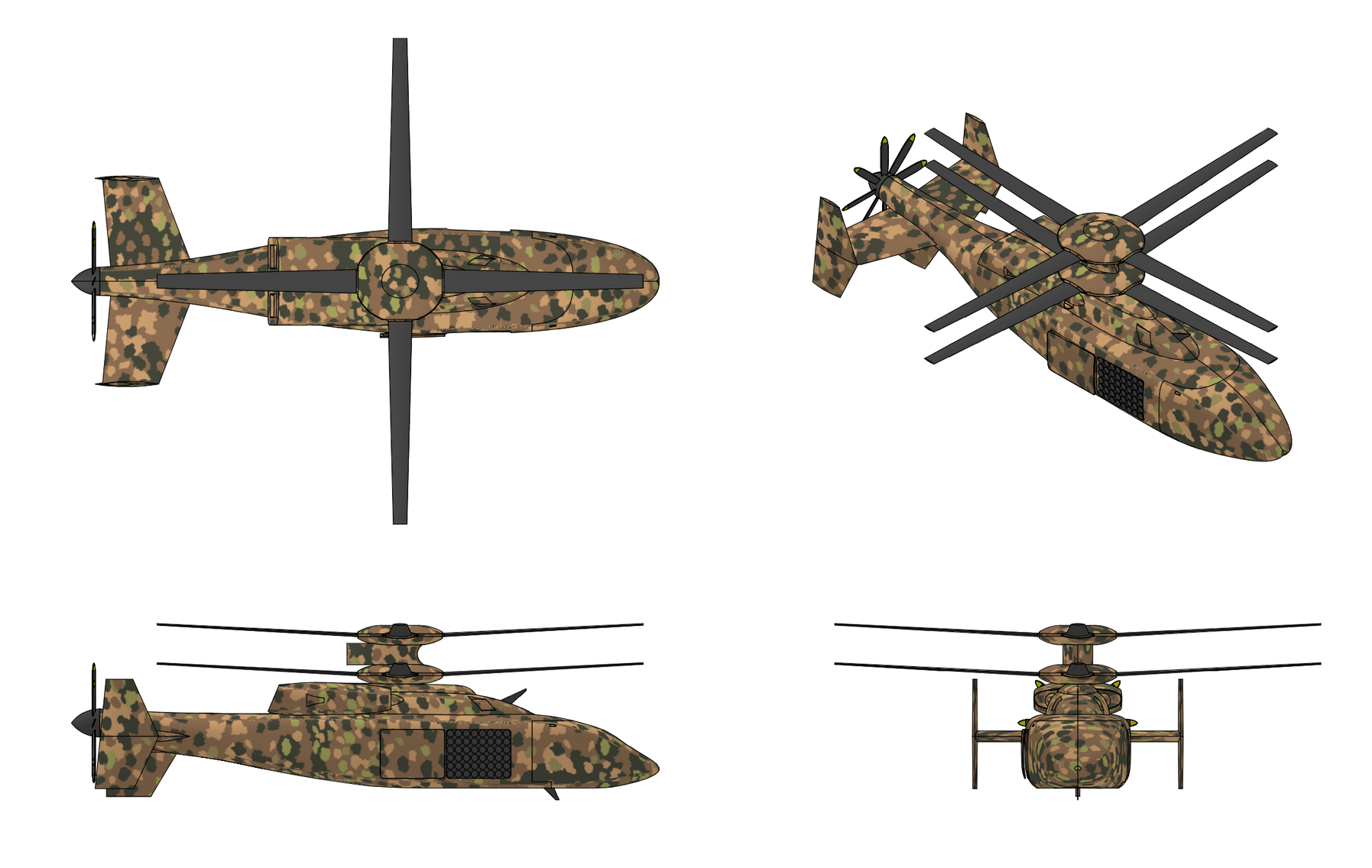
The general arrangement of the Mantis consists of a nose section housing the EO/IR gimbal turret in a chin-mounted installation with 360° azimuthal coverage, a forward fuselage containing the avionics bay and mission systems, a center fuselage housing the fuel cell (self-sealing, crash-resistant bladder, approximately 800 liters / 600 kg lbs of fuel), the engine and main transmission mounted directly above the center fuselage on the rotor mast structural pylon, the coaxial rotor hub assembly above the engine with two four-blade rotors and the rotor control actuators, an aft fuselage containing the pusher propeller gearbox, driveshaft, and the six-blade variable-pitch propeller, and fuselage stub wings (optional) for external weapons carriage in the attack configuration.

The fuselage is a semi-monocoque composite structure with CFRP skins over a honeycomb core designed for crashworthiness and battle damage tolerance. The fuselage cross-section is a streamlined oval, approximately 1.5 meters wide × 1.3 meters tall at the maximum section, providing internal volume for fuel and avionics,. The external surfaces are treated with IR-suppressive paint (reducing solar heating and thermal signature) and are sealed against salt spray and corrosion for maritime operations.


Propulsion:
  • Name: TSM800
  • Type: Turboshaft
  • Length: 860 mm
  • Diameter: 560 mm
  • Dry Weight: 170 kg
  • Compressor: isngle-stage low-pressure centrifugal, single-stage high-pressure centrifugal
  • Combustor: annular axial-flow
  • Turbine: Single-stage LPT single-stage HPT, two-stage PT
  • Maximum power output: 1,300 kW
  • Overall pressure ratio: 14:1
  • Power-to-weight ratio: 7.6 kW/kg
  • Turbine inlet temperature:[/b 1,430 °C
  • [b]Specific fuel consumption: 0.22 kg/kW-hr
Engine: The Mantis is powered by a single SDI TSM800 turboshaft rated at 1,300 kW of takeoff power. The TSM800engine consist of four removable modules; an inlet particle separator (IPS) module, accessory gearbox module, gas generator module, and a power turbine module. The inlet particle separator (IPS) module is designed to prevent engine ingestion of sand, dirt, dust, and other debris and consists of an engine driven axial flow separator with a flow splitter, scavenge air vanes, and graphite-epoxy composite scroll fan designed to filter inlet air with minimum inlet pressure loss. The accessory gearbox module is driven by the high pressure spool using a radial driveshaft and contains the mounting points for the starter, IPS blower, oil pump, and fuel control unit. The gas generator core module consists of a two-stage centrifugal compressor, a reverse-flow annular combustor, and a two-stage axial gas generator turbine. The two-stage centrifugal compressor is designed to be tolerant to sand ingestion, foreign object damage, and inlet distortion. The combustor is a compact, high efficiency effusion-cooled reverse flow combustor. The TSM800 engine control system includes a dual-channel FADEC (full-authority digital engine control) with all electrical and optical connections to the aircraft's digital flight control system and and an engine health monitoring system to expedite engine maintenance and repair. To reduce aircraft IR signature the engine exhaust gases are routed through a two-stage infrared suppression system integrated into the upper airframe fairing between the main rotor mast and the tail empennage. The first stage mixes ambient air with the hot exhaust through a lobed film-cooling mixer, reducing peak exhaust gas temperatures by approximately 65%. The second stage routes the mixed gases through a serpentine duct that shields the hot metal components from direct line-of-sight observation from below and to the sides. The exhaust efflux is discharged through a wide, flattened slot oriented upward, where it is further diluted by the downwash from the upper rotor disc. The complete system reduces the aircraft’s 3–5 micron band IR signature by greater than 90% relative to an unsuppressed installation.

Rotor system: The Mantis uses SDI's compound coaxial helicopter propulsion system which employs a lift-offset coaxial rotor design with two contra-rotating rigid main rotors and a clutchable pusher propeller assembly. The lift-offset rotor design offloads the lift from the retreating blades by using the aerodynamic lift of the advancing blade, eliminating the potential of stall of the retreating blades and thus allowing for higher speed horizontal flight. In addition the two contra-rotating coaxial rotors produce opposing torques, eliminating the need for a tail rotor. Each of the coaxial main rotors is 8 meters in diameter and and has four rigid wide-chord active rotor blades attached to the rotor hub using a series of elastomeric pitch bearings. The rotor blades are tapered in thickness from the tip to root and employ a continuous wound carbon fiber skin bonded to a hollow graphite/epoxy honeycomb composite structure. An additional polyurethene abrasion strip is bonded to the leading edge of each rotor blade. Each hollow blade additionally contains a graphite/epoxy composite flexbeam which extends from the rotor hub to the mid-span of the blade which provides ballistic tolerance to internal detonations of HEI rounds up to 30 mm in caliber and increases the rigidity and flapping stiffness of the rotor blade to allow for closer spacing of the coaxial rotors to minimize drag in forward flight. Each rotor blade features an active vibration control system (AVCS) consisting of a trailing edge flap on each rotor blade actuated by double X-frame actuator with four single-crystal piezoelectric stack columns embedded in each rotor blade capable of defecting the trailing edge flap +/- 3°. The active flaps allow the lift generated by each rotor blade to be varied and blade-vortex interaction (BVI) induced noise and vibration to be significantly reduced by eliminating pressure fluctuations on the leading edges of the blades. A composite fairing covers each rotor hub to reduce parasitic drag in flight. Each coaxial rotor is fitted with its own rotor control system which are located concentric with the twin coaxial rotors. Each rotor control system contains four electro-mechanical servomotor actuators and a swashplate and pitch control rod assembly used to adjust the pitch of the four rotor blades of each rotor in flight. A noise and vibration reducing electronic synchrophaser mechanism is located inside the rotor control system assembly and matches the rpm and phase of both coaxial rotors by adjusting the speed of each rotor and the relative positions of each individual blade.

Transmission system: The transmission system of the helicopter transfers power from the turboshaft engine to the coaxial main rotors, the pusher propeller, and the accessory drive system. The main gearbox of the transmission system is constructed from magnesium to reduce weight and provides a speed reduction between the turboshaft engine and the pusher propeller and coaxial rotor drive shafts and is connected to the fuselage using four elastomeric isolator mounts which provide vibration isolation in the roll, pitch, and yaw directions. Power from the turboshaft engines enters the main gearbox using a turboshaft-to-gearbox drive shaft fitted with flexible couplings that allow for slight misalignment between the engine output shaft and the gearbox housing. Inside the gearbox the engine output shaft connects to an overrunning clutch and connects to both the pusher propeller shaft and a spiral bevel gear reduction set which rotates the power output 90 degrees from horizontal to vertical and then connects to a compound spur planetary gear reduction set which drives the twin coaxial main rotors. The upper rotor is driven by the lower planetary ring gear and rotates counter-clockwise while the lower rotor is driven by the lower planetary carrier and rotates clockwise. A differential rotor speed drive located inside the main gearbox is used to transfer torque from the yaw control motor to the upper planetary ring gear and permits differential rotor rpm to produce differential torque about the yaw axis. A spur gear connected to the ring gear drives an oil lubricated rotary vane pump and provides cooling oil flow to the gears and bearings of the main gearbox. The rear pusher propeller is driven by an composite drive shaft constructed from transversely wound carbon fiber reinforced PEEK (Polyether ether ketone) and which runs from the main gearbox and connects to the pusher propeller gearbox located in the tail of the aircraft. A disconnecting clutch is contained in the pusher propeller gearbox which allows the pusher propeller to be disengaged for hovering or low-speed flight. By disengaging the pusher prop the vehicle can significantly reduce its acoustic signature, entering a "Whisper Mode" where the pusher propeller free wheels at low RPM and the coaxial rotors operate at reduced speed, producing a fraction of the noise of a conventional helicopter. The transmission is designed for 30 minutes of operation after loss of lubrication (dry-run capability), ensuring that the vehicle can safely auto-rotate and land after a battle-damage-induced oil leak. The transmission mounting structure further includes crash-attenuating features that limit the loads transmitted to the fuselage in a hard landing.


Avionics:
Mantis integrates a full three-tier NEXUS architecture adapted for the compound coaxial flight dynamics. The flight control tier is a triple-redundant fly-by-wire flight controller that manages the uniquely complex control laws of the compound coaxial configuration, simultaneously controlling upper rotor cyclic and collective, lower rotor cyclic and collective, pusher propeller pitch, and active elevon deflections. The controller manages the speed-dependent rotor RPM schedule (automatically slowing the rotors as airspeed increases), the propeller clutch (engaging and disengaging Whisper Mode), and the active vibration control system. The controller operates at 400 Hz, providing the bandwidth needed for the high-agility flight regime of a compound helicopter. The flight controller also incorporates the ship motion compensation algorithms adapted for the significantly different flight dynamics of a compound coaxial helicopter in hover. The mission autonomy tier employs ASDI Lattice AI computing module that provides AI inference for autonomous mission execution across all three mission sets. For ISR missions, NEXUS manages the Mantis gimbal (automatic target detection, classification, and tracking), flight path planning (optimizing the orbit for sensor coverage while avoiding threats), and intelligence reporting (generating formatted reports and transmitting them via datalink). For resupply missions, NEXUS manages the entire delivery profile including autonomous takeoff, transit at optimum speed and altitude, approach to the delivery point (which may be a forward outpost with no prepared landing zone), landing or low-altitude cargo release, and return. For attack missions, NEXUS manages the weapons system, handles target acquisition and tracking, presents engagement options to the operator, and executes weapon release upon authorization. The mission command tier consists of the ground control station, shipboard, vehicle-mounted, or portable, which provides mission planning and supervisory control. A single operator can control two Mantis air vehicles simultaneously.

EOS 590 FLIR System: The primary electro-optical sensor of the Mantis is the SDI EOS 590 Forward Looking Infrared (FLIR) system, a multi-spectral surveillance and targeting sensor which provides day/night and all weather detection, identification, observation, and targeting of ground, sea, and air targets. EOS 590 system consists of a 4-axis stabilized and 6-axis vibration isolated sensor head containing 10 sensors including a 1920 x 1080 pixel NIR/visible CCTV camera, 640 x 512 pixel InGaAs SWIR imager, 1280 x 720 pixel InSb MWIR (3-5 μm) imager, 830 nm laser illuminator, and 830 nm laser pointer 1.06 µm laser designator, 2.06 µm holmium-doped YLF laser rangefinder with 30 kilometer range and <2 meter resolution , 6-axis IMU, and GPS-based attitude (GPS/A) sensor. The EOS 590 features five selectable fields of view including 34° x 45° ultra-wide field of view (UWFOV), 17° x 22 ° wide field of view (WFOV), 5.7° x 7.6° medium field of view (MFOV), 1.2° x 1.6° narrow field of view (NFOV), and 0.6° x 0.8° (SWIR/MWIR) or 0.21° x 0.27 ° (visible/NIR) ultra-narrow field of view (UNFOV) with up to 4x continuous electronic zoom capability. The EOS 590 FLIR turret is mounted underneath the nose of the helicopter and is capable of traversing 360° in azimuth and +20 ° to -105°in elevation at a slew rate of up to 170°/s. Features of the EOS 590 optical system include AI enabled sensor fusion of visible/NIR, SWIR, and MWIR video outputs as well as automatic target recognition (ATR) and moving target indicator (MTI) capability and both moving map and augmented reality overlay display capability. Georeferenced line of sight steering modes include a georeferenced auto mode which focuses sensor line-of-sight on a fixed target using embedded digital terrain elevation data, georeferenced aided mode which adds a variable line-of-sight offset that continually adjusts to the speed of a moving target, and a georeferenced lock mode which enables locking the sensor line-of-sight onto georeferenced target. The system also includes additional pattern steering modes including angular scanning pattern, automated SAR scanning scanning for search & rescue missions, and stand-off observation mode which scans an area defined defined by a geographic center (latitude &longitude). Far target location (FTL) capability using the laser rangefinder and an onboard 9-axis IMU and GPS-based attitude (GPS/A) sensor allows the 10-digit GPS grid location of targets tracked by the sensor and illuminated by the system's laser rangefinder to be generated. To support automatic target recognition capability the EOS 700 runs SDI's "Sentient" AI-powered object detection and tracking software which detects and identifies targets and other objects of interest in the the electro-optical sensor feed. The system runs on an SDI Lattice GPGPU AI supercomputer with 275 TOPS of INT8 performance. The machine learning algorithms used by Sentient are trained on a library of multispectral data for both search characteristics and feature extraction and detects both stationary and moving objects which on land include vehicles, people, and weapon systems in complex terrain and environments. Sentient is capable of detecting objects as small as 2x2 pixels with persistent tracking functionality that separate tracks for each detected object even when they overlap or pass behind temporary obstructions. Objects of interest in the scene are surrounded by a color coded box which includes the detected target probable identification with a real time updating confidence interval assessment. Additional features enabled by Sentient include image registration capability that automatic aligns the thermal and EO sensor feeds to compensate for parallax and time sync differences, blind and semi-blind deblurring methods that use estimated point spread functions (PSF) to counteract atmospheric and motion blur, radial and tangential lens dewarping, thermal dehazing functions designed to mitigate the effects of haze, smoke, and dust by employing local adaptive compensation for atmospheric particle dispersion, and image blending of thermal and visible channels that automatically adjusts blending factor for day and night and local weather conditions, and sensor fusion of thermal and visible channels. The EOS 590 also includes embedded mapping functionality using SDI's HydraVision software which takes EO/IR sensor feed from the sensor and incrementally stitches it together and geo-registers it to create immediate and immersive detailed 3D georeferenced maps which provide real-time information on dynamic terrain, obstacles, boundaries, and other environmental features. High definition FLIR imagery is streamed from the aircraft to ship based control station using a SDI Ku band (14.40-14.93 transmit and 15.15-15.35 GHz receive) tactical high bandwidth datalink (THBD) compatible transceiver on the aircraft which can stream imagery at up to 45 Mbps at line-of-sight ranges up to 300 kilometers.


FMG 90 Multi-Mode Radar System: The FMG 90 Multi-Mode Radar System is Ku band (15.2 GHz to 18.2 GHz) high resolution, synthetic aperture radar (SAR) mounted in the aircraft's nose radome which provides high-resolution all-weather radar imaging and ground target tracking capability to complement the EOS 590 electro-optical sensor system. The FMG 90 has a slant range of 3 to 45 kilometers (30 km in 4 mm/hr rain) and provides both spotlight mode and stripmap mode synthetic aperture radar imaging capability with a 0.1 m resolution in spotlight mode and 0.3 m resolution in stripmap mode. Both SAR modes support coherent change detection (CCD) using the UAV ground control station which can interfere two SAR images of the same scene and measure any decorrelation in pixels between the two images in order to detect subtle changes in the two scenes.The radar also includes a ground/dismount moving target indicator (GMTI/DMTI) mode with the ability to detect and track vehicles moving over 10 kph and individual persons moving over 1 kph at ranges of 4 to 25 kilometers with the ability to cross-cue the EOS 590 FLIR in narrow FOV modes to provide visual identification of tracked targets. The FMG 90 hardware mounted in the aircraft includes a radar electronics assembly (REA) containing a Ku-band waveform generator, RF interconnect, digital receiver, ADC, and signal processing computers and the gimbal assembly containing a 3-axis stabilized gimbal with the antenna transmitter traveling-wave tube amplifier (TWTA) and a 6-axis fiber optic gyro based IMU and carrier phase GPS navigation and motion compensation system. The traveling-wave tube amplifier antenna transmits with a maximum power of 320 watts and is capable of scanning +/- 135° on either side of the aircraft's centerline.

EOS 480 Hyperspectral Mine Detection system: The EOS 480 is a long-wave infrared (LWIR) hyperspectral sensor designed to detect and locate both surface and subsurface minefields during day, night, and limited visibility conditions. The EOS 480 system includes an infrared spectrometer, telescope, stabilization system an detector array coolers which are enclosed in a sealed pod which is designed to be mounted on a hardpoint underneath the aircraft's fuselage. The system uses a pushbroom hyperspectral imager with a 256 x 256 pixel HgCdTe focal plane array (FPA) cooled to 55° K operating in the 7.5 to 11.5 μm wavelength which collects imagery in 256 separate spectral bands along with a 2 x 12,000 pixel 3-color CCD linescan camera boresighted to the hyperspectral infrared imager. Both hyperspectral imager and CCD linescan camera share a common 3-axis (roll, pitch and yaw) gyroscopically stabilized mirror system which removes the effects of aircraft motion from the image and allows the imager to scan a +/-20° swath on either side of the aircraft's ground track. The sensor is designed to be flown at a speed of 70 knots an altitude of around 90 meters which results in an approximately 65 meter wide ground swath with sufficient sensor resolution (<25 mm spatial resolution) to detect mines above and below the surface. Hyperspectral sensor data, differential GPS derided position data, time data, and CCD TV imagery from the system are stored on a IDE disk drive inside the sensor unit where the data is then streamed to the aircraft's ground control station upon completion of the flight mission. Processing of the imagery is done on the ground station which uses a MIDAP (Minefield Detection Algorithm Processor) running multiple mine-like object (MLO) detection algorithms to detect both surface and buried minefields. Surface mines are detected by analyzing temperature and emissivity anomalies along the surface while buried mines are detected by analyzing temperature differences between the disturbed soil over a buried land mine and the surrounding undisturbed soil with operation in multiple spectral bands allowing emissivity anomalies such as rocks or vegetation to be filtered out by the algorithm. Detection performance of the system includes an 80% probability to detect a pattern of buried mined, 90% probability to detect a pattern of surface mines, 80% probability to detect a group of scatterable surface mines, and a 70% probability to detect an individual buried mine. Detected minefields are geotagged with ten-digit GPS grid coordinates are uploaded to a minefield track file which is then distributed across battle management system communication networks to advancing ground units to warn them of minefields in their current operating area.

FMG 140 Foliage Penetrating Radar System: For imaging targets under foliage the Mantis can be fitted with an SDI FMG 140 foliage penetrating synthetic aperture radar (SAR) system mounted to a pod suspended under the fuselage. The 6.4 meter long airfoil cross-section pod weighs 270 kg and contains an electronically scanned ultra-high frequency (UHF) conformal linear array antenna. The pod is attached to the fuselage via a rotating swivel joint which lets the pod rotate +/- 45° off centerline. The radar is capable of electronically scanning +/- 45° in both azimuth and elevation which gives the system complete 360° scan capability around the aircraft. The radar provides booth GMTI (Ground Moving Target Indicator) and SAR (Synthetic Aperture Radar) and operates with a center frequency of 350 MHz with a peak transmit power of 4.0 kW. Operating in the UHF (P band) frequency range the radar is capable of of penetrating through most foliage and is unaffected by rain, snow, dust, or other weather conditions. The radar has a maximum instrumented range of 50 kilometers and is capable of tracking moving dismounted soldiers and vehicles at ranges up to 30 kilometers through foliage cover. When used in synthetic aperture radar mode the radar is capable of generating 1.0 meter resolution imagery at slant ranges up to 25 kilometers which can be be used to detect and identify hidden vehicles, surface to-air missiles, artillery systems, and forward operating based concealed by overhead foliage cover. Like with the aircraft's other sensors radar data from the FMG 140 is transmitted to the aircraft's ground control station in real time using the aircraft's Ku band tactical high bandwidth datalink (THBD) compatible transceiver.


Ground Control:
The Mantis is controlled using an SDI compact wideband transceiver (CWT) terminal enabling two-way RF transmission in the UHF-band (400-470 MHz), L-band (1000-1999 MHz), S-band (2.00-2.50 GHz), C band (4.40-6.00 GHz), and Ku bands (14.40-14.93 transmit and 15.15-15.35 GHz receive) between the control station and aircraft. The aircraft is controlled primarily using SDI's Ku band (14.40-14.93 transmit and 15.15-15.35 GHz receive) tactical high bandwidth datalink (THBD) system which uses a narrow-band 200 kbps uplink for vehicle, sensor, and armament control and and a wide-band 45 Mbps downlink to transmit FLIR or radar imagery from the aircraft back to the control station. The tactical high bandwidth datalink (THBD) also allows the drone to be controlled remotely by other THBD equipped aircraft including SDI's AKH 80 Reaper helicopters whose crew can remotely order the Mantis to fly to specific grid coordinates an altitudes and can remotely take over the aircraft's sensors to acquire and designate targets for their own weapons and/or to remotely fire the Manti's armament at an acquired target.
Last edited by The Technocratic Syndicalists on Mon Jun 08, 2026 5:20 am, edited 39 times in total.
SDI AG
Arcaenian Military Factbook
Task Force Atlas
International Freedom Coalition


OOC: Call me Techno for Short
IC: The Kingdom of Arcaenia

User avatar
The Technocratic Syndicalists
Minister
 
Posts: 2346
Founded: May 27, 2015
Inoffensive Centrist Democracy

Postby The Technocratic Syndicalists » Thu Nov 12, 2020 8:56 pm

Image


S-900

General Characteristics:
  • Role: Wide-body airliner
  • Crew: 2 pilots
  • Seating:
      Standard (2-2-2): 200 (18J + 182Y)
      High Density (2-3-2): 230 (230Y)
      Exit limit: 244
  • Length: 44.5 m
  • Wingspan: 36.0 m
  • Height: 11.0 m
  • Wing area: 135 m2
  • Empty Weight: 45,000 kg
  • Fuel Weight: 20,000 kg
  • Max Payload: 20,000 kg
  • Max Takeoff Weight: 85,000 kg
  • Powerplant: 2x SDI SDI TPM580 Propfan engines, 20,000 kW each
Performance:
  • Maximum Speed: Mach 0.85
  • Cruise Speed: Mach 0.83
  • Range: 8,000 km
  • Service ceiling: 13,000 m
  • Wing loading: 571 kg/m2
  • Takeoff length: 2,200 m
  • Landing length: 1,600 m


Overview:

The S-900 is an advanced technology widebody, twin-aisle airliner designed by SDI Aerospace systems. The S-900 features an integrated modular avionics suite, digital fly-by-wire flight control, advanced dual-hydraulic dual-electric (2H2E) flight control system, extensive use of composites in the airframe primary and secondary structure, and advanced fuel-efficient contra-rotating propfan engines which in combination with a drag reducing hybrid laminar flow control (HLFC) result in significantly lower fuel burn and operating costs relative to comparable airliners. The S-900 is produced jointly by SDI and by Aeronox of The Macabees who owns a 25% workshare of the S-900 program and are responsible for producing a variety of the aircraft's subystems and the majority of the aircraft's structure including the wings and several of the fuselage sections at their plant in Macabea. Final assembly of all S-900's occurs at SDI's Isenstadt plant in Isenstadt, Arcaenia


Design & Construction:
The S-900 is a relatively conventional subsonic airliner with a cylindrical fuselage 4.8 meters in diameter, high aspect ratio wings, and a T-tail with rear-mounted engines. The propfan engines are mounted at the rear of the fuselage rather than under the wing to allow room for the propeller discs and to minimize noise inside the cabin. The aircraft features extensive use of composites and other advanced materials including GLARE (GLAss REinforced) fiber-metal laminate, aluminum-lithium, and graphite epoxy and fiberglass composite.

The fuselage primary structure comprising the skin panels, frames, and longitudinal stringers of the pressurized shell—is constructed from GLARE (GLAss REinforced) fiber-metal laminate. GLARE is a hybrid material system consisting of alternating layers of thin aluminum alloy sheets (0.2–0.5 mm thick, 2024-T3 or 7475-T76 alloy) and S-2 glass fiber/FM94 epoxy prepreg layers, autoclave-bonded into a monolithic laminate panel. GLARE 3 is used for for crown panels (cross-ply glass layers providing biaxial fatigue resistance for the hoop-stress-dominated crown) while GLARE 4 for side and belly panels (unidirectional glass layers biased in the hoop direction for optimal fuselage pressurization load paths). The fuselage is manufactured using large-panel splice construction. GLARE skin panels up to 10 meters long and 3 meters wide are produced in an autoclave, then joined using mechanically fastened longitudinal and circumferential splices. Stringers are roll-formed from GLARE sheet and adhesive-bonded to the skin panels with supplementary mechanical fasteners for fail-safety. Fuselage frames are machined from aluminum-lithium alloy 2099-T83, selected for its high specific stiffness and compatibility with the GLARE skin. The forward and aft pressure bulkheads are monolithic composite structures formed from graphite-epoxy. The wing primary structure including upper and lower skin panels, front and rear spars, and ribs is constructed from third-generation aluminum-lithium alloys. The upper wing skin panels, loaded primarily in compression during positive-g maneuvers, are machined from 2199-T8E74 plate, which offers 5 percent lower density and 10 percent higher specific compressive strength than conventional 7150 alloy. The lower wing skin panels, loaded in tension, are machined from 2060-T8E30 plate, optimized for superior fatigue and damage tolerance performance in tension-dominated loading. Wing spars are machined from 2099-T83 extrusions, and ribs from 2099-T83 plate. The central wing box is constructed from graphite-epoxy (IM7/8552) composite, laid up and cured as an integrated structure with co-bonded spars and rib posts. The composite center box exploits the high specific strength and stiffness of CFRP in a region where fatigue loading is less severe than in the outboard wing, and where the design is dominated by static strength and stiffness requirements. The center box is joined to the aluminum-lithium outer wing panels through mechanically fastened Ti-6Al-4V titanium alloy fittings.

Graphite-epoxy composite materials are used extensively for aerodynamic secondary structures and non-primary components where their formability, low weight, and corrosion resistance provide maximum benefit. Composite structures on the aircraft include the ailerons and aileron tabs, inboard and outboard trailing edge flaps (including the adaptive variable-camber mechanisms), leading edge slats, the nose landing gear doors and main landing gear doors, all engine nacelle fairings, the wing-tip devices, the radome, and the entire structure aft of the rear pressure bulkhead. This aft fuselage section includes the fuselage tailcone and empennage support structure, the T-tail vertical stabilizer (fin) torque box, the horizontal stabilizer torque box, and all moveable tail surfaces (rudder and elevator). The empennage structures employ a multi-spar torque box design with co-cured skins and spar caps,

The S-900 wing is designed for high aerodynamic efficiency at the design cruise condition of Mach 0.783 at 12,000 meters cruise altitude. The planform features a geometric aspect ratio of 9.6:1, increasing to an effective aspect ratio of approximately 10:1 when the advanced wingtip devices are included. The quarter-chord sweep angle is 25°, optimized to offer an ideal balance for delaying shockwaves at Mach 0.83 cruise while generating strong lift during slow-speed flight. The wing employs a gamily of supercritical airfoil sections developed specifically for compatibility with the aircraft's HLFC system. The airfoils feature a long, favorable pressure gradient on the upper surface extending to at least 60% chord, achieved through careful contouring of the leading edge radius and upper surface curvature. This extended favorable gradient is the aerodynamic prerequisite for maintaining laminar boundary layer flow over the forward portion of the wing, and the airfoil design is tightly coupled with the HLFC suction distribution. The lower surface profile is designed for a controlled shock-free or near-shock-free pressure recovery to minimize wave drag. The airfoil thickness-to-chord ratio varies from approximately 14% at the root to 10% at the tip, with a slight increase in relative thickness at the outboard wing stations to improve structural efficiency and increase the chord depth available for fuel tankage. The wing terminates in advanced blended winglets of composite construction, incorporating a smooth blend from the wing planform through a curved transition to a near-vertical winglet of approximately 2.2 meters height. The winglets are designed to reduce induced drag at the design cruise condition by approximately 4–5 percent, and incorporate a raked tip extension at the winglet apex to further reduce tip vortex intensity. The winglet profiles are aerodynamically tailored to operate in the modified tip-region flowfield created by the high-aspect-ratio wing planform, and their structural attachment to the aluminum-lithium outer wing is through a composite-to-metal transition fitting. At the maximum wingspan of 36.0 meters (including winglets), the aircraft remains within ICAO Code C lateral limits.

The S-900 features a unique hybrid laminar flow control (HLFC) system designed to reduce the aircraft's drag by maintaining laminar flow over portions of the aircraft's wings. The hybrid laminar flow control system combines aspects of traditional active laminar flow control (LFC) and natural laminar flow (LFC) shaping principles and delays the transition of the flow from laminar to turbulent through active suction of air through small perforations in the leadings edge of the wing combined with airfoil shaping designed to create a pressure gradient favorable to laminar flow on the remaining upper surface of the wing. The hybrid laminar flow control system is activated in climb at 3,000 meters altitude and operates through the cruise phase, being designed to produce laminar flow on the wing from the leading edge to the upper 60% wing chord and provides a 10 to 12% drag reduction during flight. The leading edge of the wing consist of micro-perforated Ti-6Al-4V titanium alloy sheet metal suction panels, supported by a built-up aluminum-lithium alloy nose beam and lightweight built-up aluminum-lithium ribs. The titanium panels are electron-beam perforated with holes of approximately 50 to 65 μm in diameter at a pitch of 0.5–0.8 millimeters. The perforated titanium sheets are bonded to individual trapezoidal section graphite-epoxy tubes, which are bonded in their turn to graphite-epoxy inner skins. The suction panels, in addition to their function as LFC. suction conduits, also act as stiff structural assemblies that maintain the aerodynamic contour and carry air loads to the support ribs. Kevlar-epoxy collector plenums, two per panel, run chordwise the width of the panel and are connected to the main suction duct. Surface boundary layer air is drawn through the perforated skin into suction channels which are connected to suction panel manifolds through metering holes, which are varied in spacing and diameter to produce the desired flow distribution along the wing chord. The suction panel manifolds then feed into span wise collector ducts through connector tubes equipped with flow-limiting nozzles to establish the pressure gradients required to maintain the desired span wise suction flow distribution. Suction pressure for the system is provided by a single stage centrifugal suction compressors for each wing, driven by a single 35 kW 270 VDC permanent magnetic electric motor located in each wing-body fairing. Control of the suction system involved developing a suction plenum pressure schedule that is correlated against flight parameters such as altitude, Mach number, and wing angle of attack. The suction compressor is operated to maintain the desired suction pressure by varying the motor speed and a set of inlet guide vanes (IGV) in each suction compressor. A separate HLFC system is provided for the T-tail horizontal stabilizer and the vertical stabilizer (fin). The tail HLFC system operates on the same principles as the wing system but is powered by a dedicated third turbo-compressor unit located in the aft fuselage. The tail HLFC system maintains laminar flow to approximately 50% percent chord on both tail surfaces, contributing an additional 2 to 3% reduction in total aircraft drag. The tail HLFC suction panels are also perforated titanium, with hole geometry optimized for the lower Reynolds numbers and different pressure distributions encountered on the tail surfaces.

Each wing leading edge also includes a liquid cleaning system designed to clean debris and insect impacts off the wing surface to maintain laminar flow. A film of liquid is exuded near the stagnation point and covers the leading edge and upper wing surface, cleaning off any debris or insects the wing encounters. The liquid film is maintained during takeoff and climb to 1,500m. Cleaning fluid is routed from a storage tank to the wing leading edges, the distribution system incorporating a proportioning unit to control the pressure drop to each distribution manifold. The distribution manifold contains a porous stainless steel wire mesh that ensures even distribution of the fluid over the length of the manifold. The manifold is designed to allow either cleaning fluid or anti-ice fluid (ethylene glycol and alcohol-based anti-icing and de-icing liquid) to be dispensed on the wing surface.


Vehicle Management System & Flight Control Surfaces:
Vehicle Management System (VMS): The S-900 fly-by-wire system is managed by four vehicle management computers (VMCs), organized as two pairs. VMCs 1 and 2 are the primary pair (command channels), and VMCs 3 and 4 are the secondary pair (monitor and backup channels). The primary VMCs are implemented using dissimilar hardware architectures (VMC1 uses a PowerPC-based processor, VMC2 uses an ARM-based processor). The secondary VMCs provide a simplified, independently certified control law (direct law with stability augmentation) as a reversionary mode in the event of dual primary VMC failure. The VMCs receive inputs from quadruple-redundant air data and inertial reference systems (ADIRS), triple-redundant pilot side-stick controllers (force-sensing, non-moving), and triple-redundant rudder pedal assemblies. The S-900 FBW system implements three control law modes: Normal Law (full envelope protection, C*U speed stability, bank angle hold, automatic pitch trim, alpha and load factor limiting, and automatic coordination of VC/DFS with flight controls), Alternate Law (reduced envelope protection, engaged automatically upon single VMC failure or partial sensor loss), and Direct Law (proportional stick-to-surface commands with basic stability augmentation, engaged upon dual primary VMC failure, using the secondary VMCs). Normal Law also incorporates automatic gust load alleviation using the spoilers and DFS system, reducing wing bending loads during turbulence encounters and allowing a lighter wing structural design. The control laws are designed for carefree handling throughout the flight envelope, with hard protections against stall, overspeed, over-g, and over-bank that cannot be overridden by the pilot in Normal Law.

Control surfaces: The S-900 employs a 2H/2E (two-hydraulic, two-electric) fly-by-wire (FBW) flight control system which replaces the conventional three independent hydraulic systems with two segregated hydraulic systems (designated Green and Yellow) and two segregated electrical power channels (designated E1 and E2), achieving equivalent or superior dispatch reliability and survivability with reduced system weight, fewer fluid lines, and lower maintenance burden. Each hydraulic system is powered by a pair of engine-driven pumps (one on each engine, allowing each engine to drive each hydraulic system), supplemented by an AC motor-driven pump (ACMP) powered by the respective engine’s generator bus for redundancy. The hydraulic systems operate at 350 bar (5,000 psi), allowing smaller actuators and lines for equivalent force output. Each hydraulic system powers one set of primary flight control actuators plus one channel of leading edge slat actuation, trailing edge flap actuation, landing gear extension and retraction, nosewheel steering, and wheel brakes. The two electrical channels are driven by a pair of 250 kVA variable-frequency (360–800 Hz) integrated drive generator (IDG) and provide power to electro-hydrostatic actuators (EHAs) to act as a backup to the hydraulic primary actuators on all primary flight control surfaces. Each EHA is a self-contained unit incorporating an electric motor, a miniature hydraulic pump, and a hydraulic actuator cylinder, powered by its respective electrical bus. In the event of a complete hydraulic system failure, the EHAs on the E1 and E2 channels provide full flight control authority sufficient for safe flight and landing. Additionally, the electrical channels power the spoiler actuators (electro-mechanical actuators, or EMAs), the horizontal stabilizer trim actuator (dual-motor EMA), and the Variable Camber/DFS flap actuators.

The S-900 features a Variable Camber (VC) and Differential Flap Setting (DFS) that provides continuous in-flight optimization of the wing trailing edge geometry. The system uses adaptive dropped-hinge trailing edge flaps as variable-geometry aerodynamic surfaces that deflect by small amounts (typically ±2° to ±5°) during cruise to reshape the effective wing camber distribution. The VC system operates by symmetrically deflecting the inboard and outboard trailing edge flap segments to modify the wing camber, thereby shifting the spanwise lift distribution to the optimum for the current flight condition. At the beginning of cruise, when the aircraft is heavier, the VC system deflects the flaps slightly downward (positive camber) to increase the wing design lift coefficient, maintaining the aircraft at the optimum lift-to-drag ratio without requiring a higher angle of attack that would compromise the HLFC pressure gradient. As fuel is burned and the aircraft becomes lighter, the VC system progressively retracts the flaps toward the faired position, reducing camber and maintaining the optimum lift distribution as the required lift coefficient decreases. The DFS function extends the VC concept by allowing asymmetric and spanwise-varying flap deflections. By differentially setting the inboard and outboard flap segments on each wing, the DFS system can tailor the spanwise load distribution to minimize induced drag at off-design conditions, manage wing root bending moments during gusts, and compensate for asymmetric loading due to fuel burn asymmetry. The DFS system operates in coordination with the HLFC system, the flight control computers continuously monitor the HLFC suction parameters and adjust the VC/DFS settings to maintain the pressure gradient conditions necessary for laminar flow. This integrated VC/DFS-HLFC control strategy is designed to deliver an additional 3 to 5% fuel burn reduction beyond the benefits of the HLFC and VC systems operating independently.


Propulsion:
  • Name: SDI TPM580
  • Type: Three-shaft Propfan
  • Length: 3,780 mm
  • Diameter: 1,240 mm
  • Dry Weight: 1,000 kg engine core, 3,200 kg with gearbox and propellor
  • Compressor: five stage LPC, eight stage HPC
  • Combustor: annular counter-flow combustor
  • Turbine: single stage HPT, single stage LPT, four stage LPT
  • Maximum power output: 20,000 kW
  • Overall Pressure ratio: 40:1
  • Specific fuel consumption: 0.18 kg/kW-hr
  • Turbine inlet temperature: 1,590 °C
  • Power-to-weight ratio:: 6.25 kW/kg
The S-900 is powered by two SDI TPM580 propfan engines each delivering 20,000 kW (27,000 shp) of sea-level static power and up to 130 kN of thrust at takeoff. The TPM580 is a two-spool, counter-rotating geared pusher propfan engine. The power section consists of a gas generator core and accessory gearbox. The low pressure spool of the gas generator consists of a five stage axial low pressure compressor (LPC) with a 5:1 pressure ratio which is driven by a single stage low pressure turbine (LPT). The high pressure spool consists of a seven stage axial high pressure compressor (HPC) with an 8:1 pressure ratio driven by a single stage high pressure turbine (HPT). The low pressure compressor is a five stage axial design consisting of a drum rotor, a cast Ti-64 (Ti-6Al-4V) titanium case, aluminum/graphite abradable tip seals, and boron/aluminum composite compressor blades. The seven-stage high pressure axial compressor has variable inlet guide vanes with aluminum graphite abradable seals, and an integral rotor drum. The blades in the first two stages of the high pressure compressor are constructed from Ti- 829 (Ti-5.5Al-3.5Sn-3Zr-1Nb-0.25Mo-0.3Si) titanium alloy while the blades in the remaining stages are constructed from Inconel 718. The combustor is a two-stage rich burn, quick mix, lean burn (RQL) combustor. The RQL combustor splits the combustion process into two stages. Within the primary zone, a fraction of the total air reacts with all of the fuel resulting in fuel rich combustion products. This allows for both low flame temperature and high reaction stability. Exiting the primary zone, the combustion emissions react with the remaining air, via dilution jets, in the quick mix region before entering the secondary zone. With the addition of this remaining air, the mixture is converted from fuel rich to fuel lean. As a result, the combustion flame temperature is kept low and carbon monoxide (CO) and unburned hydrocarbon (UHC) are largely eliminated. Design combustor exit temperature is 1,590° C. The single stage high pressure turbine and single stage low pressure turbine employ cast single crystal airfoils with ceramic tip seals and combined film cooling and convection cooling using bleed air from the high pressure compressor. The four stage power turbine employs uncooled turbine blades and rotors constructed from Ti-48Al-2Cr-2Nb gamma titanium-aluminide alloy.

The gear system of the engine consists of a differential planetary gearbox that takes the single rotational input from the power turbine and divides it into two contra-rotating output shafts. The gearbox is a compound epicyclic design with a first-stage star gear set driving the forward rotor and a second-stage planetary set driving the aft rotor through a concentric counter-rotating shaft arrangement. The overall gear reduction ratio is approximately 7.5:1, reducing the LP turbine shaft speed of approximately 5,500 RPM at cruise to a propeller speed of approximately 730 RPM. The gearbox is designed for a continuous rating of approximately 29 MW with an approximately 45:55 power split between the front and rear row of blades, and incorporates advanced bearing designs, an integrated oil cooling system, and a chip detection and vibration monitoring system for health management. The the gearbox is designed for a 30,000 hour mean time between unscheduled removal (MTBUR). The propfan module includes two rows of blades, twelve in the front row (counter-clockwise rotation viewed from the rear) with a 3.75 meter diameter and ten in the rear row (clockwise rotation) with a 3.70 meter diameter. The propfan blades are constructed from 3D woven graphite/epoxy composite airfoil with a Ti-6Al-4V titanium alloy leading edge erosion guard over a rigid polymethacrylimide (PMI) based structural foam core. The propfan blades feature hydraulic blade actuation with variable blade pitch, mechanical pitch locks, full reversing and feathering capability, overspeed protection, and mechanical minimum blade angle features. Both propeller stages incorporate full-feathering hydraulic pitch change mechanisms (PCMs) with independent pitch control for each blade. The pitch change system allows continuous variation of blade pitch angle from a fine-pitch (high-RPM ground idle) setting through the normal operating range to a fully feathered zero-thrust position for engine-out conditions. The hydraulic PCM is powered by the engine gearbox oil system and incorporates a fail-safe spring-loaded feathering mechanism that drives the blades to the feathered position in the event of hydraulic pressure loss. A mechanical pitch lock prevents the blades from going below the flight fine pitch stop in the event of a PCM malfunction, preventing a propeller overspeed condition. The rotating cowlings of each propeller are carbon fiber/PMR-15 polyimide composite face sheets with a honeycomb Ti-6-Al-4V titanium alloy core. The engines are mounted via pylons on the rear fuselage sides. The rear-fuselage mounting position places the propeller disc plane approximately 2.5 meters aft of the aft pressure bulkhead, maximizing the structural attenuation path for propeller noise transmission into the cabin. The fuselage skin in the aft section adjacent to the engines incorporates a double-wall construction with a constrained-layer damping treatment consisting of a viscoelastic polymer layer sandwiched between the GLARE outer skin and an inner aluminum sheet, providing approximately 8–12 dB of additional noise attenuation compared to a single-wall structure. External noise is managed primarily through advanced blade shaping (tip sweep, blade twist optimization, and reduced tip speed) and is the primary noise reduction mechanism. The unequal blade count between the forward and aft rotors (12 and 10 respectively) also distributes interaction tone energy across more spectral lines, reducing the perceived noise level. The engine nacelle lips and inter-rotor duct surfaces incorporate acoustic liners tuned to the blade-passing frequency. The combined effect of these measures is designed to achieve a cumulative noise margin of 15–18 EPNdB below current ICAO Chapter 14 limits.

The TPM580 includes a dual-channel full authority digital electronic control system (FADEC). Control modes include independent control of blade pitch and propellor speed allowing variable synchrophasing control of each propfan engine to minimize engine noise and vibration, protective measures for regulating turbine-inlet temperature and preventing inadvertent engine overspeed or overtorque, and fault modes allowing for propellor blade feathering and gas generator compressor/turbine section windmilling if an engine fails or has to be shut down in flight. The FADEC control system is housed in a dual-channel electronic control unit containing circuitry connected to various engine sensors whose inputs are used by the FADEC system to control fuel flow, propeller pitch, variable compressor vanes and stators, bleed air flow, and other systems to optimize the performance of the engine throughout the flight envelope. Sensors are additionally linked together to the aircraft's control through a dual redundant fiber-optical data bank which integrates engine status and diagnostics with the aircraft's flight control system.


Cockpit & Cabin:
Cockpit: The S-900 flight deck features a two-crew glass cockpit with six large-format (38 cm diagonal) LCD primary flight displays, a head-up display (HUD) system for each pilot, and an integrated electronic flight bag (EFB) with dual Class 3 EFB tablets. The aircraft's six main cockpit displays include an inner Flight Information Display (FID) for each pilot integrating all flight task information into one, an outboard Navigation Display (ND) for each pilot which displays the flight plan information including all aeronautical charts for the current flight management task, and two central displays on the central console shared between the pilots which include an integrated EICAS (Engine Instrument and Crew Alerting System) and system display designed to display all necessary engine and and aircraft system information and a lower Multi-Function Display (MFD). The flight information display is designed to be split quadrant wise into a primary flight display (PFD) window which includes basic T-instrument cluster functionality (attitude indicator/artificial horizon, airspeed Indicator, altimeter, heading indicator) with a supplemental engine indicator and flight mode annunciator, a lateral window with a display of the nose-up lateral flight path map, a vertical situation display window which displays a vertical profile display with vertical trend vector. The primary flight display includes an integrated 3D synthetic vision system consisting of a CG generated 3D terrain view generated using an onboard Enhanced Ground Proximity Warning System (EGPWS) terrain database which can be overlaid behind the attitude indicator instead of the typical blue/brown artificial horizon, enhancing the pilot's terrain awareness and providing the pilots with a virtual VMC (Visual Meteorological Condition) environment even in the low visibility condition. The display normally shows the typical blue/brown artificial horizon and switches to 3D terrain view when the flaps are set to anything but the “up” position (ie during landing and takeoff), when an EGPWS caution/warning alert is active, when the aircraft descends to decision height (DH) or minimum descent altitude (MDA), or when the altimeter setting is set to manual setting mode. The 3D terrain display can also be toggled on or off by each pilot. The primary flight display also includes a graphical flight mode annunciator which displays autopilot and autothrottle (AP/AT) system modes using colored texts with different shape outlines to improve the auto-pilot mode situation awareness. In addition to the text indication indicating the current autopilot/auto-throttle setting a colored illumination box is assigned to each mode allowing the pilot to recognize the AP/AT modes intuitively by the combination of the illumination pattern and it’s coloring. Engaged AP or AT mode is indicated with a green or magenta background, a green background showing the current mode manually engaged by the pilot while magenta coloring shows the current vertical mode managed by the FMS. Each AP and AT mode also has a specific indicator shape assigned to it that gives the pilot the second cue to recognize the current engaged mode other than by the text. The vertical display is intended to improve the terrain awareness and the vertical flight plan/path awareness and displays a terrain cutout and vertical flight profile along the expected lateral path which are displayed with the aircraft position and vertical trend vector as an aid to visually check the deviation from the planned vertical profile or to determine the vertical speed (VS) or flight path angle (FPA) value when VS or FPA modes are engaged. The engine N1 parameter (low pressure spool RPM) is also indicated on the primary flight display to provide engine thrust information to the pilot without them having to look at the center EICAS and system display. Tie supplemental N1 indicator on the primary flight display shows actual, expected and commanded N1 value for each engine as well as the N1 indicator on the EICAS which allows the pilot to manage the thrust within the flight information display while engine indication on the EICAS display is reserved for engine health monitoring. The Navigation Displays are displayed left/right outboard of the Flight Information Displays and are designed to integrate all flight management information and functions. Below and outboard of each navigation display is a cursor control Device (CCD) and a multifunction keypad (MFK) which provide additional precision input and data entry capability to the touchscreen display. The navigation display features a graphical map integrated with an electronic chart viewer which displays the flight plan route and the aircraft position's along with detected and predicted weather information which is overlaid onto a terrain profile generated from the aircraft's onboard EGPWS terrain database. Controls for the navigation display including scroll and zoom of the map and route modification are through the touchscreen itself along with the CCD while the multifunction keypad allows for inputting text based data.

The S-900 includes SDI's LNAS (Low Noise Approach System), a pilot assistance system which is designed to minimize both noise and fuel burn during aircraft approach. The LNAS system is integrated into the flight information display's vertical situation display (VSD) and displays the aircraft's current energy level in the form of summed potential and kinetic energy over the vertical profile of the flight path, informing the pilots of the energy balance during the entire approach along with relevant speed and height reductions and calculates the most energy-efficient descent from cruising altitude to landing, allowing the approach to be carried out with minimum engine thrust and minimum possible deployment of noise-intensive speed brakes. LNAS also calculated approach impacts due to changes in wind conditions or air traffic control instructions which are also displayed on the VSD. Using LNAS the aircraft is approach is designed to get the aircraft as close to the runway as possible before flaps, landing gear, or speed brakes are deployed in order to minimize drag for as long as possible while also minimizing noise on approach.

Cabin: The S-900 fuselage has an external diameter of 4.8 meters and an internal cabin diameter of 4.5 meters. The fuselage cross-section is circular, which provides the most structurally efficient pressure vessel shape for the GLARE laminate construction. Below the cabin floor, the lower fuselage accommodates containerized cargo in a single-aisle arrangement using LD3-45 half-width containers or bulk cargo. The cargo hold has a volume of approximately 28 cubic meters. The cargo hold floor incorporates a powered cargo loading system compatible with standard airport ground handling equipment. The standard cabin configuration provides a true twin-aisle layout with six-abreast seating in a 2+2+2 arrangement. This configuration delivers economy class seats with a width of 47 cm measured between armrest centers, two aisles each 51 cm wide, and a seat pitch of 81 cm. Every passenger is no more than one seat from an aisle, eliminating the discomfort of the middle seat that is a persistent source of passenger dissatisfaction in conventional six-abreast narrowbody configurations. The twin-aisle arrangement also provides two parallel boarding and deplaning paths, which extensive simulation and airline operational data from widebody aircraft indicates reduces passenger boarding time by approximately 30 to 40% compared to a single-aisle configuration for the same number of passengers. The standard two-class configuration seats 200 passengers including 18 business class passengers in a 2+2 arrangement at 97 cm pitch with 53 cm wide seats, and 182 economy class passengers in the 2+2+2 arrangement. The business class cabin occupies the forward section of the passenger deck, separated from economy by a class divider with galley and lavatory facilities. For low-cost carrier and high-density charter operations, the cabin can be configured in a seven-abreast 2+3+2 arrangement. In this layout the economy seats are 43 cm wide with aisles of 46 cm. Even in the high-density configuration, the twin-aisle design is retained, and the resulting seat width remains comparable to or greater than current narrow body airliners. The all-economy 2+3+2 configuration accommodates up to 230 passengers at 74–76 cm pitch

The cabin environmental control system (ECS) maintains a cabin altitude of no more 1,800 m at the design cruise altitude of 12,000 meters. The lower cabin altitude is enabled by the superior fatigue performance of the GLARE fuselage structure, which can sustain the higher differential pressurization loading with less fatigue penalty than conventional aluminum. The lower cabin altitude significantly reduces passenger fatigue, dehydration, and the incidence of ear discomfort during flight. Overhead stowage bins are of the pivoting bin design, providing approximately 65 liters of stowage volume per passenger in the standard 2+2+2 configuration, sufficient to accommodate one full-size IATA-compliant roller bag per passenger. Cabin lighting employs a full-spectrum LED system with automated circadian rhythm programming. Cabin noise levels at cruise are targeted at 78 dBA or below in the forward cabin and 82 dBA or below in the aft cabin (adjacent to the CROR engines), achieved through the combination of the rear-mounted engine position, the double-wall fuselage acoustic treatment, active noise cancellation transducers in the cabin sidewall panels, and vibration-isolated seat track mounting. Cabin infotainment is provided by an SDI AetherLink Air 6G satellite internet system, delivering full-cabin WiFi with fiber-optic equivalent internet speeds enabling 4K streaming, real-time cloud gaming, video calls, and near zero-latency browsing from takeoff to touchdown.


Aircraft systems:
Electrical System: Each engine drives a 250 kVA variable-frequency (360–800 Hz) integrated drive generator (IDG) providing the primary AC electrical power. The variable-frequency architecture eliminates the constant-speed drive (CSD) mechanism used in fixed-frequency 400 Hz systems, reducing weight and improving reliability. A 10 kVa ram air turbine (RAT) and a 100 kVa APU-driven generator provide emergency and ground power. The electrical distribution system uses a 230 VAC primary bus with auto-bus-tie capability, stepped down to 115 VAC and 28 VDC for subsystem loads. The power transformation network uses two transformer rectifier units (TRU) with 5.5 kVA each for normal operation (transform 400/230 VAC to 28 VDC), one TRU with 5.5 kVA for emergency operation (transforms 400/230 VAC to 28 VDC), and one static inverter with 2 kVA (transforms 28 VDC to 400/230 VAC). Power management and distribution is via primary electric power distribution centers (PEPDC) and two secondary electric power distribution centers (SEPDC) located below cockpit along with six secondary
power distribution boxes (SPDB) in cabin and two SPDBs in cargo compartment.Lithium-ion main batteries (two units, 50 Ah each) provide essential bus backup for a minimum of 30 minutes following complete generator failure.

Environmental Control System: The ECS is a bleedless architecture drawing ram air through electric-motor-driven cabin air compressors (CACs). The elimination of engine bleed air for cabin pressurization improves engine SFC by approximately 1 to 2% (since the engine no longer needs to provide high-pressure bleed air) and allows independent optimization of the cabin pressurization schedule regardless of engine power setting. The ECS provides a cabin altitude of 1,800 meters or below at cruise, a cabin airflow of approximately 4.7 liters per second per passenger, and HEPA filtration of all recirculated air. The system also provides anti-icing for the engine intake via electric heater mats in the nacelle lips.

Fuel System: Fuel is carried in integral wing tanks including eft and right main tanks in the outer wing, and a center tank in the composite center wing box with a total capacity of approximately 24,000 liters. The fuel system incorporates a fuel tank inerting system (FTIS) using hollow-fiber membrane nitrogen-enriched air (NEA) generation to reduce the oxygen concentration in the fuel tank ullage to below 12%, significantly reducing the risk of fuel tank explosion. Fuel feed and transfer is managed by AC motor-driven fuel pumps with full cross-feed capability between the left and right engine feed systems. The fuel management system automatically sequences fuel burn from the center tank (burned first to reduce wing bending relief) to the wing tanks, and incorporates fuel temperature monitoring to ensure fuel remains above its freezing point during extended high-altitude operations.
Last edited by The Technocratic Syndicalists on Thu May 14, 2026 9:48 pm, edited 21 times in total.
SDI AG
Arcaenian Military Factbook
Task Force Atlas
International Freedom Coalition


OOC: Call me Techno for Short
IC: The Kingdom of Arcaenia

User avatar
The Technocratic Syndicalists
Minister
 
Posts: 2346
Founded: May 27, 2015
Inoffensive Centrist Democracy

Postby The Technocratic Syndicalists » Mon Nov 16, 2020 4:59 pm

Image


S-1200

General Characteristics:
  • Role: Wide-body airliner
  • Crew: 2 pilots
  • Seating:
      2-class: 290 (24J + 266 Y)
      1-class: 360 (360Y)
      Exit limit: 380
  • Length: 56.7 m
  • Wingspan: 52.0 m
  • Height: 19.7 m
  • Wing area: 280 m2
  • Empty Weight: 86,000 kg
  • Fuel Weight: 52,000 kg
  • Max Payload: 40,000 kg
  • Max Takeoff Weight: 160,000 kg
  • Powerplant: 2x SDI RM900 HyperFan engines, 270 kN each
Performance:
  • Maximum Speed: Mach 0.87
  • Cruise Speed: Mach 0.85
  • Range: 9,300 km
  • Service ceiling: 13,000 m
  • Wing loading: 571 kg/m2

Overview:

The S-1200 is a large, widebody, medium to long range, subsonic airliner designed by SDI Aerospace systems. The S-1200 is designed for high short to medium range cruising efficiency and features innovative features such as a primarily composite fuselage and wing structure, bleedless ultra-high bypass variable pitch geared turbofan engines, SDI More Electric Aircraft (MEA) architecture with an advanced 2 electric / 1 electro-hydraulic (2E/1EH) flight control architecture and fully electric cabin ECS and wing ice protection systems, adaptive variable camber flap system, and hybrid laminar flow control. The S-1200 is produced in two versions, the base S-1200 passenger version which can transport 290 passengers in a 2-class configuration to a distance of 9,300 km, and the S-1200F freighter version which can transport 54,000 kg of payload to a maximum range of 6,000 km. The S-1200 is produced jointly by SDI and by Aeronox of The Macabees who owns a 35% workshare of the S-1000 and S-1200 programs and are responsible for producing a variety of the aircraft's subsystems and the majority of the aircraft's structure including the wings and several of the fuselage sections at their plant in Macabea. Final assembly of all S-1200's occurs at SDI's Isenstadt plant in Isenstadt, Arcaenia.


Design & Construction:
The S-1200 features a conventional design for an airliner with a tubular fuselage, low mounted wing, and empennage with two horizontal and single vertical stabilizers. The tubular fuselage has a diameter of 6.2 meters and tapers at the rear of the aircraft into a blade-shaped tail cone which contains the aircraft's auxiliary power unit. The wing uses supercritical airfoils and has a 9:1 aspect ratio with distinct sharklets to reduce wingtip vortex formation. The wing airfoil sections are supercritical with divergent trailing edges tailored to sustain laminar flow on the upper surface to just short of the shock. Laminar flow on the upper wing surface is initiated with a hybrid laminar flow control system (HLFC) which ingest boundary layer air through an active suction system using perforated skins on the forward portion of the airfoil just ahead of the front spar. Forward portions of the horizontal and vertical stabilizers and the engine nacelles also have similar HLFC systems. The fuselage and turbulent portions of the wing and tails also feature a riblet surface texture to reduce parasitic drag. The landing gear is arranged in a tricycle configuration with two main gear struts featuring four-wheel main landing gear bogies and a single nose gear. Hydraulically actuated, carbon-carbon fiber multi-disk brakes are provided in each of the twelve main gear wheels.

The S-1200 features a unique hybrid laminar flow control (HLFC) system designed to reduce the aircraft's drag by maintaining laminar flow over portions of the aircraft's wings and tail. The hybrid laminar flow control system combines aspects of traditional active laminar flow control (LFC) and natural laminar flow (LFC) shaping principles and delays the transition of the flow from laminar to turbulent through active suction of air through small perforations in the leadings edge of the wing combined with airfoil shaping designed to create a pressure gradient favorable to laminar flow on the remaining upper surface of the wing, shifting the the transition to turbulent beyond 50% chord. The hybrid laminar flow control is optimizes for the aircraft's design cruise speed of mach 0.85 at an altitude of 10,000 meters and is designed to produce laminar flow on the wing from the leading edge to the upper 50% wing chord, upper and lower 50% chord of the vertical and horizontal stabilizer, and 60% chord on the engine nacelles and produces a roughly 10% overall aircraft drag reduction. The active suction system uses a microperforated, CNC laser drilled Ti-6Al-4V titanium alloy sheet which forms the leading edge of the wing, empennage, and nacelles which is bonded to the underlying CFRP (carbon fiber reinforced polymer) leading edge structure. Rib-integrated compressors, seven per wing and one per horizontal and vertical stabilizer, are used to suck in boundary layer air through the microperforated skin and through a set of throttle holes in the underlying CFRP leading edge structure. The compressors are mounted to wing integrated suction ribs which in addition to supporting the mass of the compressor act to sealing the suction system while also functioning as regular wing ribs. Each compressor consists of a three-stage axial compressor with a 2.75:1 overall pressure ratio driven by an integral permanent magnet synchronous motor which provides 15 kW of suction power at a maximum compressor speed of 100,000 RPM. Each compressor includes its own power electronics module (PEM) which receives power from one of the aircraft's two HVDC networks and converts it to three phase AC power to drive the motor. Both the motor and power electronics module are convection cooled. On the wings the hybrid laminar flow control system is subdivided into seven submodules each consisting of a continuous laser drilled titanium leading edge, a suction rib with an internal compressor, a Krüger flap and its dedicated deployment and retraction mechanism, and an inductive wing ice protection system (iWIPS). Similar modules (without the Krüger flaps) are used for both horizontal stabilizers, the vertical stabilizer, and the engine nacelles. On the wings the compressor in each submodule is accessible through a maintenance hatch in the suction rib which is accessible after the Kruger flap has been deployed. The Krüger flaps, which are part of the aircraft's high lift system, also act to shield the wind leading edges against insects or debris impacts when deployed during takeoff and landing. The inductive wing ice protection system (iWIPS) is designed to protect the leading edges from ice build-up and replaces a traditional bleed-air driven wing ice protection system with an inductive, electric based system which uses contact free induction-based heating of the perforated titanium suction skin to prevent or eliminate ice build up on the wings, empennage and nacelles. The system uses a double layer of inductive coils made from copper litz wire which are placed between the titanium outer skin and the inner CFRP leading edge structure and held in place with 3D-printed polymer brackets which are attached to the CFRP structure. When the system is powered alternating current in the coils creates a magnetic field which induces eddy currents in the electrically conductive titanium skins, causing the outer titanium skin to heat up as a result of the Joule effect. The system is powered by the aircraft's twin HVDC power buses, with frequency converters in each used submodule used to convert the HVDC power to three phase AC power for the coils. The iWIPS is continually active during the take-off, climb, descent and approach and landing segments, only being deactivated during the cruise segment (when the HLFC system is activated) where the air at cruise altitude is too dry for ice to form on the wings, empennage or nacelles.

The S-1200 is constructed by weight from 60% carbon fiber reinforced polymer (CFRP) and carbon fiber reinforced PEEK composites,15% aluminum-lithium alloys, 15% aluminum and titanium metal matrix composites, and 10% other materials. The primary structures of the wing and fuselage are constructed from graphite/epoxy composites using SDI's proprietary ICARUS (Innovative Composite Architecture for Reliable Unitary Structures) composite manufacturing technology. ICARUS uses seamless co-cured structural panels formed through-thickness stitching of dry composite preforms which are resin infused using controlled atmospheric pressure resin infusion (CAPRI) and then cured in an out-of-autoclave process to create large, highly structurally efficient and damage tolerant composite structures which eliminate the need for mechanical fasteners and have significantly reduced part counts and fabrication and assembly times compared to conventional composite structures. ICARUS composite panels contain carbon fibers that are pre-kitted in multi-ply stacks with a 44/44/12 percent distribution of 0, 45, and 90° plies that are are used to build up the desired thickness and configuration. The panels are bi-directionally stiffened using unidirectional pultruded carbon rods to provide structurally efficient stiffening in one direction while foam-filled frames are positioned perpendicular to the rod-stiffeners to provide stiffening in the other direction. All stiffener flanges are stitched to the skin and no mechanical fasteners are used for joining. The integral stiffeners increases the structurally efficiency of each panel while the use of stitches instead of fasteners provides significantly more damage tolerance. ICARUS panels are created and cured entirely at atmospheric pressure and temperature, eliminating the need for curing ovens and autoclaves and allowing significantly larger composite structures to be created compared to legacy composite manufacturing methods. On the S-1200 the nose, wing upper surface, wing lower surface, raked wingtips, vertical stabilizer, horizontal stabilizer, and tailcone are all formed using large single-piece ICARUS panel structures. The center fuselage is formed using several ICARUS panel barrel assemblies joined together which consist of the outer bi-directionally stiffened skin panels stabilized by longitudinal stringers and lateral-vertical frames which are reinforced at select points to accept concentrated loads from the wing, tail and nose landing gear. The primary wing structure is a two-spar box formed by front and rear web and upper and lower ICARUS skin panels stiffened by longitudinal stringers. Skins are stabilized by regularly-spaced wing ribs selectively reinforced to accept concentrated loads from flap brackets, engine pylons and main landing gear. Secondary internal wing structure is a mix of ICARUS composite and aluminum-lithium alloys. The horizontal and vertical stabilizers are constructed similarly to that of the wing. Flaps, ailerons, spoilers and the cabin and landing gear doors are constructed from a higher strength graphite fiber reinforced polyether ether ketone (PEEK) thermoplastic composite which are formed using a robotic layup of fiber-reinforced thermoplastic tapes which are then consolidated into skins and weld stringers in a single automated step to make large single piece monolithic structures. Lightning strike protection, a potential issue for all-composite aircraft structures, is addressed through an aluminum micro-wire grid embedded into the ICARUS panels on the fuselage and wing structure which renders them electrically conductive. Other materials used in the S-1000 are titanium alloys and both aluminum and titanium metal-matrix composites. An SCS-8/RSR-Al metal-matrix composite consisting of SCS-8 silicon carbide fibers embedded in a 6061 aluminum alloy is used for the engine pylons while the same composite using Ti-6Al-4V titanium alloy as the matrix is used for the landing gear. Titanium and titanium-aluminide (Tial) metal matrix composites are also extensively used inside the engines. Both types of metal matrix composites are formed using SiC fibers blended with aluminum or titanium alloy powder which are then compacted into billets and sintered using a rapid solidification rate process to produce the final part. Conventional titanium alloys are extensively used inside the engines, for the aircraft leading edges, and for the aircraft's high pressure hydraulic lines which are constructed from Ti-3Al-2.5V alloy tubing.


Vehicle Management System & Flight Control Surfaces:
Vehicle Management System (VMS): The S-1200 vehicle management system (VMS) is a quadruple redundant fully digital fly-by-wire control system responsible for controlling the aircraft in flight. The VMS is quadruple redundant with four independent channel running synchronously. Each channel is powered by a different power bus and includes a Primary Flight Computer (PRIM) consisting of an SDI AeroCore™ multi-core flight control & vehicle management computer (VMC), secondary flight computer (SEC), and sensor suite including air data inertial reference unit (ADIRU), cockpit control sensors, and actuator position sensors. All inputs and outputs data from each channel are cross fed to the other three channels with a voting algorithm continuously comparing the output from each channel to determine the correct signal and ensure that no single or double failure can compromise the aircraft's safety. Each of the four redundant channels receives identical input from the pilot's controls and then using its sensors calculates the necessary commands to move the control surfaces (such as ailerons, elevators, and rudder). The outputs of these four parallel systems are then compared by a voting algorithm which uses simple majority voting, the algorithm selects the output value that is agreed upon by three or four channels. The dissenting channel is identified as faulty and its output is ignored. The system can tolerate the failure of any single channel and can also tolerate two failures and continue to operate long as the failures do not both occur in the same direction (e.g., two channels outputting a high value, and two a low one). If two channels fail, the remaining two healthy channels will produce a consistent, valid output, which the voting logic will select. The system also uses historical voting data as a virtual fifth channel to resolve cases where two channels fail in agreement. The aircraft's flight control modes include normal law, alternate law, and direct law. Normal Law is the standard mode and provides three axis control, flight envelope protection and active gust and maneuver load alleviation. Normal law sub-modes include a ground mode which is active whilst the aircraft is on the ground, flight mode which provides pitch attitude, load factor, high speed, high-AOA and bank angle flight envelope protection along with auto-trim and low-speed protection, and a flare mode which is automatically engaged when the radar altimeter indicates 30 meters above ground during landing and provides for a direct sidestick to elevator relationship, at 15 meters AGL then trimming the nose slightly down and requiring the pilot to progressively move the sidestick rearward in order to emulate the conventional control input for landing. Alternate Law is a degraded mode with reduced protections which is activated after multiple system failures in the normal law mode, the flight control law degrading following a predefined sequence from the standard normal law into one of two alternate laws (ALT1 or ALT2). Alternate Law 1 (ALT1) control law degradation results from faults in the horizontal stabilizer, a single elevator fault, loss of multiple slat or flap position sensors or a failure of three or more air data inertial reference units (ADIRUs) and combines normal law lateral mode with alternate Law pitch modes which eliminates the automatic stall protection of the standard normal mode low speed protection which is replaced by a low speed stability protection which introduces nose down demand based on indicated air speed (IAS) instead of angle-of-attack (AOA) and implements an aural "STALL" warning to the pilots. ALT1 also eliminates the normal mode alpha floor protection, requiring the pilots to manually recover from a stall. Normal mode load Factor and bank angle Protections are retained in ALT1, with high speed and high angle of attack protections entering alternate law modes while pitch attitude protection is lost. Alternate Law 2 (ALT2) control law degradation results when both engines flame out or with faults to all spoilers, or multiple aileron faults and combines alternate pitch and yaw modes with direct law roll mode. In addition to normal mode protections lost in ALT1 (pitch attitude and low speed protection) ALT2 also loses bank angle protection, high angle of attack protection, and high speed protection with only load factor protection remaining from the standard normal law. In direct law, which represents a complete failure of the autopilot system, all protections are lost and the sidesticks now directly control the control surfaces. Direct law results from multiple elevator faults, failure of all four primary flight computers, or failure of all four air data inertial reference units (ADIRUs). In direct mode auto trim is also lost and the pilots must apply manual trim via the horizontal stabilizer. The secondary flight computers (SEC) are normally on standby and provide complete aircraft control in direct law only. Should all primary and secondary flight computers fail the S-1000 also has an electrical backup control system called the Backup Control Module (BCM) which is totally segregated from the normal flight controls system and includes a backup power supply (BPS) and a backup control module (BCM) which controls the inboard ailerons, elevators, and the rudder which are actuated using electrical power from one of the aircraft's twin HVDC networks. Direct control laws are used whenever the electrical backup system is active with the addition of pitch motion damping and yaw damping functions.

Control surfaces: The control surfaces of the S-1200 include two ailerons, two elevators and a trimmable horizontal stabilizer, one rudder, 12 leading edge Kruger flaps, four Slotted Camber Tab trailing edge flaps, and 10 spoilers. The ailerons plus asymmetrical spoiler and flap deflection are used for roll control, trimmable horizontal stabilizer with elevators used for pitch control and pitch trim, and the single rudder is used for yaw control. Lift and drag modulation is also provided by symmetrical deployment of trailing edge variable camber flaps. For control surface actuation the S-1200 employs an advanced 2 electric / 1 electro-hydraulic (2E/1EH) with twin electrical systems providing primary flight surface control and an electro-hydraulic system acting as a backup. All major control surfaces are both electrically and hydraulically powered using a combination of conventional hydraulic actuators, electro-hydrostatic actuators (EHA), and electrical back-up hydraulic actuators (EBHA) which combine a conventional servo-controlled hydraulic actuator with an integral electro-hydrostatic actuator (EHA) backup system, having the same performance as an SHA in the hydraulic (normal) mode and a reduced deflection rate in the electrical (backup) mode. The electro-hydrostatic actuators and the backup electrical back-up hydraulic actuators (EBHA) are powered directly by the aircraft's twin independent +/− 270 VDC high voltage direct current (HVDC) networks (HVDC1 and HVDC2). The aircraft's single electro-hydraulic system operates at 55.1 MPa (8,000psi) and consists of a single self-contained electro-hydraulic power package (EHPP) which integrates hydraulic power generation through electro-motor pump units (EMPs) and associated hydraulic system equipment and electronic power and control/monitoring systems in an integrated package which forms a single line replaceable unit (LRU) that can be removed from the aircraft. The electro-hydraulic power package supplies the aircraft's hydraulic circuit consists of a bootstrap hydraulic reservoir, reservoir integrated manifold with integrated filters, valves and sensors, two electro-motor pump units (EMPs) with motor control electronic (MCE) modules. Each electro-motor pump (EMP) consists of a hydraulic fluid cooled permanent magnet synchronous motor (PMSM) driving a fixed displacement internal gear pump (IGP) which delivers a rated flow rate of 120 L/min at 10,000 RPM. The motor control electronic (MCE) modules consist of the power drive electronics which receive electrical power from the aircraft's two independent high voltage direct current (HVDC) networks and convert it to three phase AC power to drive the electro-motor pumps (one electro-motor pump being driven by one of the aircraft's two HVDC networks) along with dual channel (control/monitoring architecture) control computers which performs motor pump control functions. Two redundant pressure sensors in the EHPP also provide closed loop control feedback to each MCE. The electro-hydraulic power package (EHPP) modules is contained in the aircraft's aft electrical equipment (E-E) bay and can be removed as a single line replaceable unit (LRU). Interfaces between the EHPP and aircraft are the electric connector of the MCEs which connect to the aircraft's twin HVDC networks, a connector on the MCE which connects them to the aircraft's Ethernet-based data network communication system, and the high pressure hydraulic ports which connect to the aircraft's hydraulic circuit. The aircraft's ailerons and elevators are each actuated by an electro-hydrostatic actuator (one EHA connected to each electrical network) and a hydraulic servo actuator while the rudder is actuated by a by a pair of electro-hydrostatic actuators and a hydraulic servo actuator, allowing all primary flight surface control to be performed by either electrical or hydraulic systems. Yaw dampening for the rudder is achieved through a hydraulic yaw dampener actuator while the trimmable horizontal stabilizers are driven by twin permanent magnetic synchronous motors which are mechanically synchronized through a gearbox that actuates both stabilizers. The leading and trailing edge flaps are actuated using hybrid power drive units (PDUs) which use both electrical and hydraulic motors along with hybrid wing tip brakes that can be actuated either electrically or hydraulically.

The high-lift system of the S-1200 aircraft consists of leading edge variable camber Krueger flaps and by full-span trailing edge variable camber slotted camber tab (SCT) flaps. The leading edge Krueger flaps have three positions: retracted for high speed; partially extended and sealed for takeoff, and fully extended and open for landing. The Krueger flaps retract into the underside of the wing leading edge, leaving the upper leading edge and upper forward wing surface clean to enable laminar flow across the upper wing surface as part of the aircraft's hybrid laminar flow control system, also acting to shield the wing leading edges when deployed against insect or debris impacts that would disrupt the laminar flow over the wing. The full-span variable camber trailing edge flaps are divided into inboard and outboard flap segments and are a type of multifunction wing moveable integrating the functions of a conventional spoiler, inboard aileron, and trailing edge high-lift flap system and and consists of a variable camber tracked fowler flap, a combination spoiler and sealing flap between the wing and the flap, and a lower pivoting ventilation flap on the underside between the wing and the flap which. The entire system merges primary flight control and high lift functionalities and includes variable camber differential flap functionality to optimize the wing camber in flight, permitting active load control and gust alleviation in flight and allowing the wing lift-to-drag ratio (L/D) to be optimized for different loading and cruise conditions throughout the flight. When used to provide variable camber in flight the wing surface is closed on the upper side by the sealing side and on the underside by the ventilation flap, producing a continuous surface across the entire wing without any drag producing gaps as the flap is articulated to control the camber of the wing in flight. When used for lift augmentation the upper sealing flap is retraced and and lower ventilation flap is articulated to release airflow from the underside of the wing to the upper side of the flap, the flap functioning as a slotted flap for lift augmentation. The upper sealing flap also acts as a brake flap and can be deflected upwards to act as a spoiler for both airbrake and roll control functions. The flaps are driven using geared rotary actuators which allows each flap to be deflected from 10° upwards to 45°downward. Both the upper sealing flap and lower ventilation flaps are mechanically linked to the main tracked fowler flaps using a set of geared couplings, not requiring their own drive systems. The gear linkage connecting linking the upper sealing flap and lower ventilation flaps is designed so that at negative flap positions and low positive flap positions the wing profile contour is completely sealed by the lower ventilation flap and the upper sealing flaps, eliminating any drag and noise producing gaps. At higher positive flap angles the lower ventilation flap pivots into the wing profile, generating a gap between the wing and the flap and allowing air flow from the underside of the wing to flow around the flap for lift augmentation. The spoiler function of the upper sealing flap is provided by an independent hydraulic drive that deflects the sealing flap upwards through a four-bar linkage mechanism which decouples it from the main flap linkage system when used as a spoiler. In flight the variable camber function of the flaps is used for both load alleviation and drag reduction functions, altering the wing camber to increase the aircraft's aerodynamic efficiency and to reduce the wing loads under gust conditions. The variable camber function of the flaps is also an integral part of the aircraft's hybrid laminar flow control system (HLFC) and is used to adjust the pressure distribution on the upper wing surface to maintain laminar flow. Variable camber functionality is provided by an active differential control unit (ADCU) which lets the inboard flaps move independently of the outboard flaps in order to provide variable camber functionality. Power to move the flaps is provided by hydraulic motors through a power drive unit (PDU) which turns flap torque tube which in turn operate geared rotary actuators which extend or retract the flaps with their drive arms. The Active differential control units (ADCU) are placed between the inner and outer drive shafts and consists of an active planetary differential gearbox driven by a pair of permanent magnet electric motors, a pair of shaft rotation sensors, a power-off-brake, motor control electronics, and is powered electrically by the aircraft's twin HVDC networks. The planetary differential gearbox of the ADCU is used to vary the gear ratio between the inner and outer flap drive shafts. The power-off-brake is a clutch used to disconnect the inner and outer flap drive shafts, the outer flap drive shaft being locked in place by a wingtip brake when the power-off-brake is released, allowing the inner flaps to be actuated using the PCU while the outer flaps are locked in place. Alternatively the power-off-brake can be disengaged PCU can be used to lock the position of the inner flaps while the electric motors are used to drive the outer flaps When the electric motors are clutched using the power-off-brake both inner and outer flaps actuate in tandem using the PCU.


Propulsion
  • Name:SDI RM800
  • Type:Variable pitch geared turbofan
  • Length: 4,700 mm
  • Diameter: 2,850 mm
  • Dry Weight: 4,900 kg
  • Bypass ratio: 18:1
  • Compressor:1 stage geared fan, 3 stage LPC, 9 stage HPC
  • Combustor:Annular combustor
  • Turbine: 2 stage HPT, 5 stage LPT
  • Maximum thrust: 270 kN
  • Overall pressure ratio: 90:1
  • Turbine inlet temperature: 1,760 °C
  • Specific fuel consumption: 10 g/kN-s (cruise)
  • Thrust-to-weight ratio: 5.6:1
The S-1200 is powered by two SDI RM900 HyperFan ultra-high bypass geared turbofan engines which each provide a maximum of 270 kN of sea level static thrust. The SDI RM900 uses SDI's HyperFan twin-spool geared turbofan architecture with a 2 stage HPT driving a 9 stage HPC and a 5 stage LPT driving both a 3 stage LPC and single stage fan with variable-pitch fan blades which is driven through a 4:1 gear ratio planetary gearbox in between the fan and LPC. The fan has a diameter of 3.5 meters with a design fan pressure ratio of 1.3:1 and employs 16 wide chord fan blades constructed from hollow 3-D woven carbon fiber reinforced composite (CFRP) with Ti-6Al-4V titanium alloy reinforcement along the leading edges. The fan employs a novel variable pitch fan system which allows the pitch of the fan blades to be optimized for each phase of flight and removes the need for a variable fan nozzle or a conventional thrust reverser mechanism. The variable-pitch mechanism is completely encloses by the fan centerbody and consists of a central rotary actuator with a pitch change collector ring connected using pitch arms to high strength composite fan blade tension/torsion retention straps constructed from carbon fiber reinforced PEEK (polyether ether ketone) which support the centrifugal load of each fan blade and are attached using pins to a grooved disk which acts as the blade pivot center. A hydraulic motor is used to actuate the pitch change collector ring through a worm gear drive which provided high magnification of the hydraulic motor output torque and prevents back-driving of the pitch change mechanism. The pitch change mechanism allows the incidence angle of each flan blade to be varied across a 140° range, allowing the fan blade incidence angles to be decreased at low aircraft speeds to avoid fan stall flutter and allowing the blades to be feathered or rotated past the feather position to provide reverse thrust upon landing. The 3-stage low pressure compressor has a pressure ratio of 2.5:1 and employs three Ti-48Al-2Cr-Nb titanium alloy integrally bladed rotors (IBRs) with highly swept, highly loaded controlled diffusion airfoils designed to operate at transonic tip speeds. The low pressure compressor includes abradable rub-stripped trenches for reduced tip leakage, mini-cavities to reduce endwall losses, and a full-annular modulated bleed system designed to prevent compressor surge. The 9-stage high pressure compressor (HPC) has a pressure ratio of 27:1 and employs integrally bladed rotors with highly swept, highly loaded blades employing controlled diffusion airfoils constructed from a high temperature metal matrix composite (MMC) consisting of Ti-48Al-2Cr-Nb titanium alloy (the first 6 stages) or Ti-48Al-2Cr-Nb gamma titanium-aluminide (TiAL) (the final four stages) reinforced with 30% by volume high strength (>3450 Mpa), high modulus high modulus (380 Gpa) SiC (silicon carbide) fibers. Features of the high pressure compressor include reduced interstage cavities, abradable blade tip trenches for improved internal aerodynamic efficiency, an axially-split front outer case containing variable geometry vanes in the first four stages, and a single-piece rear case accommodating the remaining stages of fixed stators. The compressor variable geometry vanes employ an electrically-driven stator vane actuation systems to replace conventional fuel-driven variable guide vane actuators. The combustor section of the engine employs an SDI FLARE Combustor, an advanced staged combustor designed to provide high combustion efficiency and reduced NOx emission. FLARE is a type of staged, lean direct injection (LDI) combustor which sequences the fuel injection through local injection zones to tailor the fuel-air mixture ratio over a large engine operating range. The lean direct injection (LDI) combustor injects fuel directly into the flame zone without a separate premixing section and burns fuel-lean throughout without a rich front end, reducing NOx emissions by minimizing local flame temperature through avoidance of local near-stoichiometric zones. Rapid and uniform fuel-air mixing in the combustor is achieved by replacing traditionally-sized fuel nozzles with multiple smaller 7-element fuel nozzles, the FLARE combustor having a total of 20 7-element injector arrays which are constructed from 3-D printed inconel superalloy along with a floatwall silicon carbide fiber reinforced silicon carbide (SiC/SiC) ceramic matrix composite combustor liner with a hafnium carbide (HfC) environmental barrier coating. Air exists the compositor at design combustor exit temperature of 1,800 °C where it then enters the two stage high pressure turbine which drives the high pressure compressor. The high pressure turbine employs silicon carbide fiber reinforced silicon carbide (SiC/SiC) ceramic matrix composite turbine blades and vanes with a zirconia (ZrO2) environmental barrier coating which are internally convention cooled using high pressure bleed-air from the high pressure compressor. Features of the high pressure turbine include low-loss, highly loaded airfoils and active clearance control for increased aerodynamic efficiency. The 5-stage low pressure turbine uses uncooled Ti-48Al-2Cr-Nb gamma titanium-aluminide (TiAL) alloy blades with silicon carbide fiber reinforced silicon carbide (SiC/SiC) ceramic matrix composite vanes and features double wall case construction to accommodate an internal clearance control system for control of blade tip clearances, low loss aft-loaded airfoils with elliptical leading edges, stepped labyrinth inner air seals to control leakage, and blade leading and trailing edge flow guides to minimize cavity recirculation losses. The low-pressure turbine directly drives the low pressure compressor and also drives the single stage variable-pitch fan through a 4:1 gear ratio planetary gearbox rated at 100,000 kW of input shaft power. Both turbine engine spools are mounted on silicon carbide reinforced Ti-6Al-4V titanium metal matrix composite shafts with the low pressure shaft being supported by a pair of high temperature active magnetic bearings (AMBs) using a high temperature capable iron-cobalt-vanadium soft magnetic alloy. .The engine active clearance control (ACC) is used to control blade tip clearances in the rear stages of the high pressure compressor, in the high-pressure turbine, and in the front stages of the low-pressure turbine. The system uses hot and cool compressor bleed and discharge air to change the temperature of the high pressure compressor, high pressure turbine, and low pressure turbine cases and therefore change their diameter. Compressor discharge air along with air is bled from the 4th and 9th stage compressor stages is bled to a series of Active Clearance Control (ACC) rings around each high pressure compressor stage and each high and low pressure turbine stage, allowing the diameter of the case at each stage to be controlled.

The RM900 engine features SDI's More Electric Engine architecture which is designed to replace all engine accessory drives and bleed systems with electrical based machines. In addition to being fully bleedless the RM800 lacks a conventional accessory gearbox and instead includes an integral High Pressure Starter Generator (HPSG) and a Fan Shaft Driven Generator (FSDG) for engine starting and electrical power generation purposes. The High Pressure Starter Generator(HPSG) is an oil cooled permanent magnet synchronous motor/generator which is mounted directly on the front of the high pressure compressor (HPC) and directly connected to the high pressure shaft. The HPSG replaces a traditional gearbox mounted air starter and during engine start draws power from the aircraft's 270 VDC High Voltage Direct Current (HVDC) electrical network via the HPSG Power Electronics Module (PEM) which converts the HVDC power to variable frequency AC power which is delivered to the HPSG during the starting mode, spinning the engine up to its ignition speed of 9,000 RPM. Power to the HPSG start each engine is provided through the engine power bus by either the APU, the opposite side engine HPSG, or by external power. Once the engine is ignited and running the HPSG is then used as a generator, delivering up to 200 kW of electrical power back from engine idle up to a maximum high pressure shaft speed of 15,000 rpm to the engine power bus through the HPSG power electronics module which convers the variable frequency AC power to a 270 VDC power which is delivered through the engine power bus back to the aircraft's electrical network. The power electronics module for the HPSG with its internal 1200V/600A Silicon Carbide IGBT module based power conversion electronics is mounted to the engine fan case and is fuel cooled using fuel from the aircraft's fuel tanks which is pumped through a heat exchanger in each power electronics module before being delivered to the engine, cooling the PEM and also preheating the fuel to improve combustion efficiency and preventing ice from forming in the fuel feed lines and filters on cold days. The Fan Shaft Driven Generator (FSDG) is an oil cooled Switch Reluctance (SR) machine positioned within the engine tail cone area and is directly driven by the engine low pressure shaft. The FSDG generates 150 kW of electrical power continually from engine idle to a maximum low pressure shaft speed of 4,500 rpm and like the HPSG delivers electrical power back to the aircraft's 270 VDC electrical system through a FDSG Power Electronics Module (PEM). Like the Power Electronics Module for the HPSG the Power Electronics Module for the FSDG is fuel cooled and and mounted on the engine fan case. In the event of an engine flameout the FSDG can continue to produce electrical power from the windmilling engine and allows for the deletion of conventional ram air turbines (RATs) for emergency power generation capability and has the ability to generate up to 25 kW of electrical power from the windmilling fan. Fuel to the engine is supplied by an electric fuel pump mounted to the engine fan case which uses a single a 40 kW permanent magnetic electrical motor driven shaft to drive both LP and HP pumps at fuel flow rates of up to 500 kg/s at a pump speed of 7,500 RPM. The fuel system also enables fuel to recirculate back to the aircraft fuel tanks to maintain fuel cooling following engine shutdown, allowing the cooling of the power electronics modules to be maintained even when fuel is not being supplied to the engine. The electric fuel pump motor and its associated power electronics module are supplied with +/- 270 VDC power from the aircraft's HVDC electrical network are are both air cooled. Fully electric, engine mounted oil pumps and scavenge pumps also replaces conventional mechanical pumped oil systems in the engine and provides oil flow for the engine and oil cooling to both embedded electric generator machines.

Each RM900 engine is controlled using an SDI D2FADEC (Distributed, Decentralized FADEC) system, a type of distributed, decentralized engine control system intended to replace legacy FADEC systems. D2FADEC distributes the functions of FADEC at the component level with each sensor and actuator in the engine being replaced with a smart sensor or actuator which includes local signal acquisition and processing capability, digital data bus communications and diagnostics and health management functionality. A fiber-optic digital communication network is then used to connect all smart modules with the central FADEC unit which performs digital data processing and communications functions. As approximately 50% of the circuitry in a traditional FADEC is used for processing and converting analog information, the entirely digital FADEC unit used in the D2FADEC system is significantly lighter and smaller than a traditional FADEC unit. The D2FADEC used in the RM800 engine employs twin conduction cooled dual-core FADEC computers (one active and one standby) mounted to the engine fan case which are connected in series to each of the smart sensors and actuators used in the engine. The smart sensors and actuators used in the system employ high temperature Silicon-On-Insulator (SOI) or Silicon Carbide (SiC) based electronics with operational temperatures of 250 ºC (SOI) and 600 ºC (SiC), SOI based electronics being used for the majority of the components with more expensive SiC based electronics used for sensors and actuators which have to operate in close proximity to the higher temperature parts of the engine. Smart sensors, smart actuators, and the central FADEC computers are connected in series using a digital fiber-optic ethernet-based network with a ring connection topology that optimizes both weight reduction and system reliability. The D2FADEC system provides centralized control of engine fuel flow, variable-pitch fan blade incidence angle control, compressor variable inlet guide vane (VIGV) and variable stator vane (VSV) actuation control, high pressure compressor and turbine clearance control management, high and low pressure spool overspeed protection control, exhaust gas temperature (EGT) monitoring, engine thrust and power management control, engine starting sequence control, and transmission of engine parameters and FADEC system status to the cockpit displays. The D2FADEC system also includes a Model Based Engine Control (MBEC) system designed to improve the engine the engine efficiency of which uses real-time on-board models for direct engine control of unmeasured engine parameters such as engine thrust, combustor exit temperature, and stall margin to tailors the control laws for the specific engine at its current condition and current environmental conditions, allowing the engine to operate with less conservative operability margins compared to legacy engine control systems which are typically designed for "worst case" scenario of an end of life (EoL) engine operating under challenging external conditions. The MBEC system also acts as a "virtual sensor" backup to existing engine sensors or for unsensed engine parameters such as thrust and turbine inlet temperature, provides maintenance action recommendation based on current engine health assessment, and engine fault detection and isolation based on both engine sensor fault detection or fault detection based on sudden engine performance shifts. The core of the MBEC system is a "digital twin" of the engine, a real-time, virtual replica of the physical engine stored on the D2FADEC processor which is continuously updated with real-world data from the engine sensor measurements to enable comprehensive simulation, monitoring, performance prediction, and optimization throughout the engine's lifecycle. The digital twin starts as an “as-designed twin” representing an ideal engine as modelled by its nominal minimum specified performance parameters. During engine acceptance testing the digital twin becomes an “as-built twin", reflecting the engine performance parameters as actually tested. When the engine then enters operational use the “as-built twin" model is continuously updated in real time with sensed engine parameters and calculated current performance values to become an "as-used" digital twin which is used by the MBEC system to control engine parameters. AI/ML functionality is also integrated into the MBEC system and is used to warn about the possibility of a critical failures, continually determine safe modes of engine operation, detect suddenly emerging faults that impede engine functionality, and identify parts of the engine that require maintenance using a neural network trained on nominal and atypical sensor outputs from each sensor in the engine.


Avionics
The S-1200 employs SDI's proprietary ASTRA (Advanced Scalable Technologies for Reconfigurable Avionics) integrated modular avionics (IMA) architecture, a type of advanced, distributed, open-architecture integrated modular avionics (IMA) system comprising common hardware, communications and application interfaces that can support all aircraft functions. ASTRA replaces all conventional Line Replaceable Units (LRUs) with common Core Processing Modules (CPM) that each host multiple avionics functions for managing the flight control system, cockpit controls, undercarriage, fuel, pneumatics, cabin environmental systems, and fire detection systems, and other aircraft systems which are loaded on the modules as software applications. ASTRA differentiates itself from traditional Integrated Modular Avionics (IMA) by separating core processing from remote Input/Output (I/O) functions, allowing for a more flexible and efficient system design capable of integrating more aircraft functions than a traditional IMA system and consists of multiple interconnected IMA systems and networks connected through communication node that can transfer data to another part of the avionic system through a shared aircraft communication network. The core processing capability of the ASTRA system is provided by advanced multi-core Core Processing Modules (CPMs) on each local IMA network which provide generic processing capabilities inside software partitions to host applications of different criticality levels. The core processing modules come in standardized
sizes and thicknesses and are packaged side by side into common rack mount chassis units. Processor heat is drawn out of the modules along the edges through advanced thermal packaging and into liquid-filled chassis walls for cooling. The locking mechanism which holds the processor modules in place also serves as a heat conduit. The chassis walls contain liquid cooling lines to remove heat, each chassis also containing its own intelligent power supply for the modules. The communication backbone of the ASTRA system is an SDI SpaceLink® architecture based Avionics Data Communication Network (ADCN) full-duplex fiber-optic communication network employing dense wave division multiplexing (DWDM) optical bus technology enabling significantly higher network bandwidth and capacity compared to legacy fiber-optic ethernet systems. The ADCN is designed to handle high-rate data streams between digitized signals sources and receivers, command packets with deterministic delivery time, data packets for distributed processing and IO, common time ticks distribution, and ultra-low latency distribution of real-time signals for synchronization and control purposes. Interfacing the SpaceLink ADCN to other interconnections (ARINC429, CAN, AFDX, etc) is provided by gateway nodes. SDI's SpaceLink fiber-optic communications architecture, originally designed by SDI for spacecraft applications, supports up to 5 Gbit/s data transfer speed on single channels with further multi-laning capability that can increase the data transfer rate further to over 40 Gbits/s using multiple channels in parallel and is designed to replace AFDX (Avionics Full-Duplex Switched Ethernet) and all other legacy communication architectures in the ASTRA system. SpaceLink includes integrated quality of service (QoS) using virtual channels to provide multiple independent communication channels over a single physical link, each channel providing priority, bandwidth reservation and scheduled QoS and operate together to result in robust QoS and providing “babbling node” protection and scheduled, deterministic communication without wasting any network bandwidth. SpaceLink also includes integrated fault detection, isolation and recovery (FDIR) support which detects, isolates and recovers from faults in the link where they occur to prevents faults from propagating and causing further errors.

The S-1200 is equipped with SDI's FlightSphere Integrated Surveillance System, an airborne sensor suite combining weather radar, traffic collision and avoidance, transponder surveillance, and terrain awareness and warning capabilities into a single system. The ISS suite includes SDI's StratoScan-8000 weather radar which provides the aircraft with comprehensive long range weather detection, analysis, and threat detection and avoidance capability. StratoScan functions include automatic operation, geographic weather correlation, overflight protection, and long range turbulence detection. The StratoScan-8000 is powered through 230 VAC 360 Hz-800 Hz power and uses an 80 centimeter diameter solid state X-band (9.375 GHz center frequency) solid state gallium nitride antenna with +/- 80° scan capability and has an 800 kilometer maximum weather detection range, 120 kilometer turbulence detection range, and 10 kilometer wind shear detection range. The radar features track while scan (TWS) capability with the ability to detect and monitor up to 48 weather cells at once with the ability to maintain a dedicated vertical scan for each detected cell. Weather cells are analyzed for active convection, lightning probability, and turbulence risk and are displayed on the pilot cockpit displays with colors (green, yellow, red) representing the assessed threat probability within each detected weather cell.


Cockpit and Cabin:
The S-1200 employs a glass cockpit instrumentation system which includes six 31 x 23 centimeter AMLCD (active-matrix liquid crystal display) touchscreen displays with 1600x1200 pixel UXGA resolution; two for each pilot and one shared display mounted between the pilots on the center console. The aircraft's six main cockpit displays include an inner Flight Information Display (FID) for each pilot integrating all flight task information into one, an outboard Navigation Display (ND) for each pilot which displays the flight plan information including all aeronautical charts for the current flight management task, and two central displays on the central console shared between the pilots which include an integrated EICAS (Engine Instrument and Crew Alerting System) and system display designed to display all necessary engine and and aircraft system information and a lower Multi-Function Display (MFD). The flight information display is designed to be split quadrant wise into a primary flight display (PFD) window which includes basic T-instrument cluster functionality (attitude indicator/artificial horizon, airspeed Indicator, altimeter, heading indicator) with a supplemental engine indicator and flight mode annunciator, a lateral window with a display of the nose-up lateral flight path map, a vertical situation display window which displays a vertical profile display with vertical trend vector. The primary flight display includes an integrated 3D synthetic vision system consisting of a CG generated 3D terrain view generated using an onboard Enhanced Ground Proximity Warning System (EGPWS) terrain database which can be overlaid behind the attitude indicator instead of the typical blue/brown artificial horizon, enhancing the pilot's terrain awareness and providing the pilots with a virtual VMC (Visual Meteorological Condition) environment even in the low visibility condition. The display normally shows the typical blue/brown artificial horizon and switches to 3D terrain view when the flaps are set to anything but the “up” position (ie during landing and takeoff), when an EGPWS caution/warning alert is active, when the aircraft descends to decision height (DH) or minimum descent altitude (MDA), or when the altimeter setting is set to manual setting mode. The 3D terrain display can also be toggled on or off by each pilot. The primary flight display also includes a graphical flight mode annunciator which displays autopilot and autothrottle (AP/AT) system modes using colored texts with different shape outlines to improve the auto-pilot mode situation awareness. In addition to the text indication indicating the current autopilot/auto-throttle setting a colored illumination box is assigned to each mode allowing the pilot to recognize the AP/AT modes intuitively by the combination of the illumination pattern and it’s coloring. Engaged AP or AT mode is indicated with a green or magenta background, a green background showing the current mode manually engaged by the pilot while magenta coloring shows the current vertical mode managed by the FMS. Each AP and AT mode also has a specific indicator shape assigned to it that gives the pilot the second cue to recognize the current engaged mode other than by the text. The vertical display is intended to improve the terrain awareness and the vertical flight plan/path awareness and displays a terrain cutout and vertical flight profile along the expected lateral path which are displayed with the aircraft position and vertical trend vector as an aid to visually check the deviation from the planned vertical profile or to determine the vertical speed (VS) or flight path angle (FPA) value when VS or FPA modes are engaged. The engine N1 parameter (low pressure spool RPM) is also indicated on the primary flight display to provide engine thrust information to the pilot without them having to look at the center EICAS and system display. Tie supplemental N1 indicator on the primary flight display shows actual, expected and commanded N1 value for each engine as well as the N1 indicator on the EICAS which allows the pilot to manage the thrust within the flight information display while engine indication on the EICAS display is reserved for engine health monitoring. The Navigation Displays are displayed left/right outboard of the Flight Information Displays and are designed to integrate all flight management information and functions. Below and outboard of each navigation display is a cursor control Device (CCD) and a multifunction keypad (MFK) which provide additional precision input and data entry capability to the touchscreen display. The navigation display features a graphical map integrated with an electronic chart viewer which displays the flight plan route and the aircraft position's along with detected and predicted weather information which is overlaid onto a terrain profile generated from the aircraft's onboard EGPWS terrain database. Controls for the navigation display including scroll and zoom of the map and route modification are through the touchscreen itself along with the CCD while the multifunction keypad allows for inputting text based data.

The S-1200 includes SDI's LNAS (Low Noise Approach System), a pilot assistance system which is designed to minimize both noise and fuel burn during aircraft approach. The LNAS system is integrated into the flight information display's vertical situation display (VSD) and displays the aircraft's current energy level in the form of summed potential and kinetic energy over the vertical profile of the flight path, informing the pilots of the energy balance during the entire approach along with relevant speed and height reductions and calculates the most energy-efficient descent from cruising altitude to landing, allowing the approach to be carried out with minimum engine thrust and minimum possible deployment of noise-intensive speed brakes. LNAS also calculated approach impacts due to changes in wind conditions or air traffic control instructions which are also displayed on the VSD. Using LNAS the aircraft is approach is designed to get the aircraft as close to the runway as possible before flaps, landing gear, or speed brakes are deployed in order to minimize drag for as long as possible while also minimizing noise on approach.

The S-1200s flight deck controls include active control side sticks along with rudder pedals, rudder trim selector, pitch trim switch, and speed brake levers. The active control sidesticks provide immediate and intuitive sensory feedback in the form of tactile cueing provided through electromechanical actuators and vibration motors in response to hand and finger motions, giving the pilots maximum situational awareness of their aircraft to reinforce stability and performance. These tactile cues are designed to give the pilot and co-pilot an improved physical "feel" for the aircraft's motions and aerodynamic limits, improving pilot situational awareness compared to older passive side stick controls. The S-1200 features fully digital, quadruple redundant fly-by-wire system with all flight controls inputs feeding into four primary flight computers (PRIMs) and four secondary flight computers (SECs) which provide aircraft control in either normal, alternate, or direct laws. The cockpit of the S-1200 also includes two digital heads up displays (HUDs) with a 35° x 26° field of view and 2560 x 1600 pixel resolution. The HUDs are used with the aircraft's SDI enhanced vision system (EVS) which uses a dual band short-wave infrared and long-wave infrared imager mounted in the nose of the aircraft to display a 2560 x 1600 pixel raster image on the HUD which is conformal to the outside scene, allowing the pilot to see runway lights and markings through fog, smoke, and other low-visibility conditions while on approach and on landing. The HUD also supports surface guidance system (SGS) capability which uses DGPS (Differential Global Positioning System) information to overlay runway, taxiway, and guidance line ques onto the heads up displays to allow the pilots to navigate during landing rollout and taxi operations in low visibility conditions.
Last edited by The Technocratic Syndicalists on Sun Oct 05, 2025 6:51 pm, edited 6 times in total.
SDI AG
Arcaenian Military Factbook
Task Force Atlas
International Freedom Coalition


OOC: Call me Techno for Short
IC: The Kingdom of Arcaenia

User avatar
The Technocratic Syndicalists
Minister
 
Posts: 2346
Founded: May 27, 2015
Inoffensive Centrist Democracy

Postby The Technocratic Syndicalists » Thu Nov 19, 2020 6:21 pm

Image

D 15 Strix

General Characteristics:
  • Role: Autonomous reconnaissance UAV
  • Crew: none
  • Length: 1.5 m
  • Width: 0.6 m
  • Height: 0.5 m
  • Rotor diameter: 2.3 m
  • Max takeoff weight: 24 kg (ISR configuration), 36 kg (strike configuration)
  • Powerplant: 6.0 kW brushless coaxial electric motor
Performance:
  • Endurance: 90 minutes (ISR configuration), 60 minutes (strike configuration)
  • Maximum speed: 70 knots (130 kph)
  • Cruise speed: 35 knots (75 kph)
  • Maximum range: 25 km
  • Service ceiling: 3,600 m DA
  • Temperature limits: -20ºC to +50ºC
Avionics:
  • EOS 540 FLIR
    • IR MWIR 1080 x 1024, 8x Optical Zoom: 24.0 - 3.0
    • EO Global shutter HD CMOS, 20x Optical Zoom: 40.0 - 2.0
    • SWIR 640x512, 2x Optical Zoom: 5.7 - 2.9
Armament (optional):


Overview:
the D 15 Strix is a group 2 vertical takeoff and landing (VTOL) unmanned aircraft system designed to provide company and battalion-level commanders with persistent, organic intelligence, surveillance, and reconnaissance (ISR) and organic precision strike capability. Strix is designed to be a man-packable system that is waterproof, weather-proof and ruggedized for field use. Each strix system can be transported in two ruggedized cases with a <50 kg total system weight and can be assembled and readied for flight by a single operator in less than 2 minutes. Strix is designed to operate fully autonomously using SDI's NEXUS Artificial Intelligence (AI) based autonomous flight control suite with embedded computer Vision and sensor fusion technology, with the ability for a single operator to plan missions and command & control multiple Strix vehicles from a single ground control terminal. Strix is intended to be a modular platform built to adapt to changing mission requirements with field swappable payloads that can easily added to the vehicle to add precision organic strike capability to the vehicle, providing tactical units with organic precision strike capability without dependence on external fire support coordination or
higher-echelon aviation assets.


Design & Construction
The Strix is a single-mast coaxial helicopter with no tail rotor, no tail boom with a fuselage that houses avionics, batteries, and the primary EO/IR gimbal payload. The fuselage is a semi-monocoque composite structure using carbon fiber reinforced polymer (CFRP) skin over a lightweight aluminum alloy internal spaceframe. The fuselage provides structural mounting for the rotor mast and motor assembly (top), the avionics bays (center), the battery bays (left and right flanks), and the gimbal payload (forward). The fuselage is sealed to and designed to be waterproof against temporary immersion to 1 meter for 30 minutes. Strix is designed for tool-less assembly by a single operator in under two minutes. The vehicle breaks down into four major modules: the fuselage/avionics module (the core unit, always assembled), the rotor mast and blade assembly (attaches to the fuselage top via a quick-lock ring), the battery packs (two units, slide into the fuselage flanks and lock with spring-loaded catches), and the gimbal payload (attaches to the forward fuselage mount via a single twist-lock connector).


Propulsion
The Strix rotor system consists of two rotor discs mounted on a common vertical axis, rotating in opposite directions. The upper rotor rotates clockwise (viewed from above) and the lower rotor rotates counter-clockwise. The two rotors are separated vertically by approximately 150 mm center-to-center), a spacing ratio of optimized to balance aerodynamic efficiency against compactness and structural weight. Each rotor has two blades blades with a radius of 1.15 m, yielding a total rotor diameter of 2.30 m. The blades employ a progressively twisted, tapered planform with a high-performance, low-Reynolds-number airfoil optimized for the operating tip speed range of 120-160 m/s. Blade construction consists of a CFRP spar with a Nomex honeycomb core trailing section and a CFRP skin, providing the stiffness-to-weight ratio necessary for precise blade tracking and minimal elastic deformation under load. The bade tips incorporate a swept and tapered planform to reduce compressibility effects and tip vortex noise. The blade chord is tapered from approximately 75 mm at the root to 55 mm at the tip, with 12 degrees of linear twist from root to tip. This twist distribution optimizes inflow distribution for hover efficiency while maintaining acceptable forward-flight performance. The blades are rigid with rotor control being achieved entirely through differential motor speed and the rotor synchrophasing system, without cyclic or collective pitch mechanisms. The two rotor discs are driven by a coaxial nested motor assembly consisting of two permanent magnet synchronous motors (PMSM) sharing a common central axis. The outer motor's stator is fixed to the airframe via the rotor mast structure while it's rotor rotor is a hollow cylinder with neodymium (NdFeB) permanent magnets bonded to its inner surface and drives the the upper helicopter rotor hub. The inner motor is nested concentrically inside the outer motor, with its the stator also being fixed to the airframe. The inner motor rotor is a solid cylinder with permanent magnets on its outer surface, rotating inside the inner bore of the outer motor's stator and drives the lower helicopter rotor hub through a concentric shaft that passes through the center of the outer motor assembly. Both motors use a Halbach array magnet configuration to maximize flux density in the air gap and minimize flux leakage, achieving a power density exceeding 5 kW/kg. Each motor produces approximately 3.0 kW of continuous power (5 kW total system) with peak power of approximately 5.0 kW each (10 kW total) for transient maneuvers. The nested configuration places both motors at the same lengthwise point on the airframe, directly on the mast axis, centralizing the heaviest rotating components at the vehicle's center of gravity and minimizing inertial coupling effects and simplifying the flight control problem. The mechanical interface between the two motors consists only of bearings, the system is fully gearless and lacks any other shafts other than the concentric output shafts, and there is no mechanical coupling between the two drive trains, with each motor being independently controllable in both speed and torque. Yaw control is achieved by differential RPM, increasing the upper rotor speed while decreasing the lower rotor speed (or vice versa) to create a net yaw torque, commanding a yaw rotation. The total thrust remains approximately constant during yaw commands because the average RPM is maintained. Total thrust is controlled by varying the RPM of both motors simultaneously (increasing both for more lift, decreasing both for less) which combined with the flight controller's altitude hold and vertical speed commands provides smooth altitude control. The motor system operates at a nominal voltage of 48V DC and incorporates internal hall-effect sensors and high-resolution optical encoders for precise angular position and velocity feedback. Thermal management is provided by a combination of aluminum motor housings (acting as passive heat sinks), thermally conductive potting compound on stator windings, and forced air cooling from rotor downwash. The Strix employs a triple-redundant, fly-by-wire flight control system (FCS) with automatic stabilization and autonomous flight capability. The FCS incorporates Autonomous waypoint navigation with precision hover hold (< 1 m CEP in winds up to 15 knots), automated takeoff, landing, and return-to-base with terrain-following capability, GPS-INS navigation with seamless handoff to vision-based navigation in GPS-denied environments, geofencing and altitude limits for operational safety automatic lost-link procedures (configurable: return-to-base, loiter at last known position,or execute pre-planned route)

The rotor system of the Strix is fitted with a high-precision synchrophasing control for both active noise and vibration cancellation. The synchrophasing system controls the relative angular position (phase angle) of the two rotor discs to achieve targeted noise reduction through destructive interference of rotor noise harmonics. With two twin-bladed rotors spinning at the same speed in opposite directions, the BPF tones from the two rotors will either reinforce (constructive interference, louder) or cancel (destructive interference, quieter) depending on the relative phase angle between the two blade sets. The synchrophasing controller continuously adjusts this phase angle to maintain the destructive-interference condition for the dominant noise harmonics, minimizing the far-field acoustic signature. Each motor is equipped with a high-resolution rotary encoder (20-bit, providing angular resolution of approximately 0.00034° mounted directly on the motor shaft. The synchrophasing controller , a dedicated FPGA-based real-time processor running at 100 MHz, reads both encoder positions and computes the instantaneous phase angle between the upper and lower rotors at a rate of 50 kHz (exceeding the rotor dynamics bandwidth). The controller maintains the commanded phase angle by making sub-millisecond adjustments to the motor drive currents, using the inner motor (lower mass, faster response) as the "follower" and the outer motor as the "leader." Phase angle accuracy is maintained to within ±0.1° under steady-state conditions and ±0.5° during transient maneuvers (gusts, attitude changes). The optimal phase angle is determined during initial vehicle characterization and stored in the flight controller, but can also be adapted in flight using a feedback microphone array (four MEMS microphones mounted on the fuselage undersurface) that measures the actual far-field noise signature and drives the phase angle toward the minimum-noise condition. In combination with the low-noise blade design (swept tips, optimized airfoil sections), the synchrophasing system is expected to reduce the vehicle's acoustic signature by 6–10 dB(A) relative to a conventional single-rotor helicopter of equivalent size and weight, a reduction that approximately halves the perceived loudness and significantly reduces the detection range by ground-based observers. The elimination of the tail rotor additionally removes the distinctive high-frequency "buzz" that is one of the most easily detectable acoustic features of conventional small helicopters.

The Strix is powered by two identical lithium-polymer (LiPo) battery packs, one mounted on each flank of the fuselage. Each battery employs lithium polymer (LiPo) high-discharge-rate cells with a nominal voltage of 44.4V (12S configuration). Each pack has a capacity of 19,200 mAh, for a total system capacity of 38,400 mAh (~ 850 Wh total energy). Each pack has a mass of 3.2 kg and measures approximately 1,000 by 80 mm by 60 mm. The two packs are connected in parallel to the main power bus with a dual-redundant power distribution unit (PDU) managing power flow from the two battery packs to all aircraft subsystems. The system distributes power to the high-Power Bus (48V nominal) which regulates power to the rotor drive motors, the avionics Bus (12V regulated) which regulates power to the flight computer, mission computer, AI processor, GPS/INS, datalink, navigation cameras, and payload bus (28V regulated) which regulates power to the gimbal drive and stabilization motors, imaging sensors, laser rangefinder/designator, weapons release mechanism. The PDU provides bus voltage regulation, overcurrent and short-circuit protection, battery cell balancing, and independent bus isolation capability. In the event of a single battery failure, the PDU automatically isolates the failed pack and redistributes loads to the remaining battery, enabling safe return-to-base flight at reduced endurance.


Avionics:
SDI NEXUS Flight Autonomy Software: The Strix integrates a scaled variant of the SDI's NEXUS Autonomous Flight Control Suite, adapted from fhe full-size UCAV architecture to the constrained SWaP environment of a man-portable tactical UAV. The three-tier autonomy architecture of NEXUS is preserved but the computing hardware is miniaturized. The Inner-Loop Flight Control tier runs on a dedicated real-time microcontroller Running at 400 MHz that manages the attitude control loops, motor speed commands, synchrophasing control, and GPS/INS navigation at 400 Hz. This partition is safety-critical and operates independently of the higher-tier autonomy functions if the AI partition fails, the vehicle maintains stable flight and can execute pre-programmed emergency procedures (return to base, hover in place, or land). The Tactical Behavior Execution tier runs on an SDI Lattice computing modules that provides the AI inference capability for autonomous mission execution. This partition runs the tactical behavior models: autonomous patrol (following a pre-planned route while the gimbal automatically scans the ground), area search (systematically searching a designated area using an optimized scan pattern), target investigation (autonomously flying to and orbiting a detected target of interest for closer examination), follow-and-track (autonomously following a moving target while maintaining a constant offset and continuously tracking with the gimbal), and perch-and-stare (hovering in a fixed position and providing persistent surveillance of an area from a fixed vantage point) The Mission Command tier resides on the ground control station, a ruggedized laptop computer running the NEXUS mission planning and monitoring interface. The operator plans missions using a map-based interface, assigns tasks to one or more Strix vehicles, and monitors real-time video and vehicle status. The system supports single-operator control of multiple Strix vehicles simultaneously, the operator issues high-level commands (go here, watch this area, follow that vehicle) and the NEXUS autonomy handles all the details of flight path planning, gimbal pointing, and obstacle avoidance.

NEXUS's AI inference partition provides several ISR-specific capabilities that go beyond basic autopilot functions, including Automatic Target Recognition (ATR) using an SDI's Sentient AI software (running on the Lattice GPU) which processes the gimbal video stream in real time, automatically detecting, classifying, and tracking objects of interest including dismounted personnel, vehicles (by type: civilian car, military truck, armored vehicle, technical), weapons (crew-served weapons, rocket launchers), and structures (tents, fortifications, checkpoints). Detected objects are annotated on the operator's display with bounding boxes, classification labels, and confidence scores. : Beyond detecting static objects, the AI monitors patterns of activity such as vehicles moving in convoy, personnel congregating or dispersing, digging activity (potential mine emplacement), and other behaviors that may indicate hostile intent. The system alerts the operator to activities that match pre-defined patterns of interest. When a Strix overflies previously surveyed terrain, the AI automatically compares current imagery against stored baseline images, highlighting changes such as new structures, disturbed earth, moved vehicles, new obstacles that may indicate enemy activity. NEXUS also compiles the AI's detections, classifications, and geo-locations into formatted intelligence reports that can be transmitted directly to battalion intelligence systems, reducing the operator's reporting burden. In addition to the baseline autonomous ISR behaviors NEXUS also supports several strike-specific autonomous behaviors including armed reconnaissance where the Strix autonomously patrols a designated route or area, searching for targets matching a pre-defined target set (e.g., "armored vehicles," "crew-served weapons," "radar emitters"). When a matching target is detected by the AI, NEXUS alerts the operator, autonomously orbits the target at an optimal engagement altitude and offset, and prepares the weapons system for employment, all while the operator evaluates the target and decides whether to engage. After weapon impact, the system will also automatically executes a battle damage assessment sequence which the gimbal slews to the impact point, captures multi-spectral imagery (EO for visual, and generates a formatted BDA report with before-and-after imagery, impact coordinates, and an AI-assessed damage category (destroyed, damaged, functional). NEXUS also supports cooperative operations between multiple Strix vehicles controlled by a single operator. In a multi-vehicle configuration, NEXUS automatically deconflicts flight paths (ensuring vehicles maintain safe separation), coordinates sensor coverage (distributing scan areas to avoid overlap and maximize coverage), hands off tracked targets between vehicles (when a target exits one Strix's area, a nearby Strix picks up tracking), and manages relay communications (one Strix can act as a communication relay for another operating beyond direct radio range of the GCS). This capability enables a single operator to provide persistent ISR coverage of a battalion-sized area of operations with two to four Strix vehicles working cooperatively, while each vehicle autonomously manages its own flight path, gimbal pointing, and obstacle avoidance. NEXUS can also execute cooperative engagement sequences where one vehicle designates a target with its laser while a second vehicle releases a SAL-guided munition.

SDI EOS 540 Electro-optical Gimbal: The primary sensor system of the Strix air vehicle is an SDI EOS 540 electro-optical sensor turret, a 15 cm diameter class (148mm OD) three-axis stabilized electro-optical/infrared gimbal providing multi-spectral imaging and target designation capability. The gimbal is mounted on a quick-release cradle at the forward ventral position of the fuselage, allowing field-level sensor swaps in under 30 seconds without tools. The EOS 540 gimbal combines mid-wave infrared (MWIR), HD electro optical (EO), and Short-wave infrared (SWIR ) imaging channels with a laser rangefinder, designator, and pointer/illuminator payload. The mid-wave infrared channel employs a 1280 × 1024 pixel resolution cooled InSb FPA with a 10 µm pixel pitch, providing thermal imagery across the 3–5 µm spectral band. The MWIR channel features a continuous zoom lens with 8× magnification with a field of view variable from 3.0° x 2.4° Narrow to : 24° x 19.2° Wide. The thermal channel enables detection/recognition/identification of vehicle size targets at 10 km /5.5 km /3.0 km, operating effectively in total darkness, through smoke, and in degraded weather conditions. The visible/EO channel employs a high-definition global shutter CMOS sensor (1920 × 1080 resolution) covering the 0.4 - 0.9 μm (visible + near-IR) range with a continuous optical zoom lens providing 20× magnification with field of view variable from 2.0° x 1.5° Narrow to 40° x 30° Wide. DRI range of the visible channel is 12 km / 6.5 km / 3.5 km against a 2.3 by 2.3 meter vehicle size target. The SWIR channel employs a 640x512 pixel InGaAs FPA with a 5 μm pitch covering the 0.9 - 1.7 μm spectral range and features excellent performance through haze, smoke, and dust; laser spot detection; camouflage penetration, and low-light-level imaging. DRI range of the SWIR channel is 8 km/4.0 km /2.5 km against a 2.3 by 2.3 meter vehicle size target. An eye-safe laser rangefinder (1550 nm, range accuracy ±1 meters to 5 km) provides precise range-to-target data at ranges out to 10 kilometers for geo-location, with far-target-location capability supported by a gimbal integrated GPS/INS system providing real time geolocation and geopointing capability. The laser designator is a diode-pumped solid-state (DPSS) laser operating at 1064 nm, providing coded laser designation for terminal guidance of SAL-equipped munitions. The designator produces a pulsed beam with adjustable PRF codes, enabling multiple simultaneous designations when operating with other assets. Maximum designation range is 10 km. The gimbal employs a three-axis (azimuth, elevation, roll) direct-drive stabilization system using frameless brushless DC torque motors and high-resolution optical encoders on each axis. Inertial stabilization is provided by a fiber-optic gyroscope (FOG) triad integrated within the gimbal housing. The stabilization system achieves a line-of-sight (LOS) jitter of less than 30 µrad RMS. The gimbal provides continuous 360-degree azimuth rotation and +20 / -120° elevation coverage. Geo-pointing and geo-stabilization modes allow the operator to designate a ground coordinate and maintain sensor boresight on that location regardless of aircraft maneuvering. To support automatic target recognition capability the EOS 550 runs SDI's "Sentient" AI-powered object detection and tracking software which detects and identifies targets and other objects of interest in the the electro-optical sensor feed. The system runs on the air vehicle's SDI Lattice GPGPU AI supercomputer with 275 TOPS of INT8 performance. The machine learning algorithms used by Sentient are trained on a library of multispectral data for both search characteristics and feature extraction and detects both stationary and moving objects which on land include vehicles, people, and weapon systems in complex terrain and environments. Sentient is capable of detecting objects as small as 2x2 pixels with persistent tracking functionality that separate tracks for each detected object even when they overlap or pass behind temporary obstructions. The processed video and metadata stream from Sentient is output to both the NEXUS computing partition for AI-driven situational awareness and autonomous decision-making and the communications system for transmission to the ground control station. Additional features enabled by Sentient include image registration capability that automatic aligns the thermal and EO sensor feeds to compensate for parallax and time sync differences, blind and semi-blind deblurring methods that use estimated point spread functions (PSF) to counteract atmospheric and motion blur, radial and tangential lens dewarping, thermal dehazing functions designed to mitigate the effects of haze, smoke, and dust by employing local adaptive compensation for atmospheric particle dispersion, and image blending of thermal and visible channels that automatically adjusts blending factor for day and night and local weather conditions, and sensor fusion of thermal and visible channels

Communications & Navigation: The Strix incorporates a dual-band encrypted digital datalink providing simultaneous command/control and high-bandwidth video downlink. The primary datalink is an encrypted, frequency-hopping software-defined radio (SDR) operating in S-band (2.4 GHz) and C-band (5.8 GHz), providing a maximum line-of-sight range of 25 km with sufficient bandwidth for real-time H.265 video streaming (approximately 10 Mbps). The SDR supports AES-256 encryption and anti-jam capabilities with with frequency-hopping spread-spectrum waveform suitable for contested electromagnetic environments and supports robust multi-node mesh networking or range extension and multi-aircraft coordination When multiple Strix and ground stations are operating in the same area, the mesh network automatically forms and optimizes routes, providing redundant communication paths that are resilient to individual node failures. As a backup system the Strix incorporates an integrated commercial LTE/5G modem for beyond-line-of-sight operations in permissive electromagnetic environments. The navigation system of the Strix combines a tactical-grade GPS/INS unit with a vision-based navigation (VBN) system for operations in GPS-degraded or denied environments. The GPS/INS unit consists of an SDI TNS 800 Tactical-grade fiber optic gyro inertial measurement unit with a dual-frequency L1/L5 GPS receiver with anti-jam and anti-spoofing capability. The SDI TNS 800 combined three closed-loop fiberoptic gyroscopes and three microelectromechanical systems (MEMS) accelerometers in a compact low SWaP-C package (500 cc, 750 gram, <7W) package with <0.05 °/hr gyro bias stability and <0.05°/√hr gyro angle walk performance. The VBN system uses a downward-facing camera array and simultaneous localization and mapping (SLAM) algorithms to maintain position accuracy without GPS. The system uses SDI's HydraNav optical-navigation system for GPS-independent midcourse guidance which combines the air vehicle's downward facing electro-optical navigation sensor with SDI's HydraVision real-time 3D mapping software and computes both absolute and relative navigation position updates through the fusion of three different HydraVision algorithms: a Stereo Terrain Correlation algorithm which captures overlapping images along the vehicle's flight path using the onboard camera and then correlates the real-time generated stereo elevation model with stored terrain references for precise geo-location determination, an Image-Based Feature Matching algorithm which matches image features in captured imagery with stored terrain image references, providing additional navigation location, and a Feature-Based Velocity Estimation algorithm which tracks image features from frame to frame to constrain inertial navigation system drift between HydraNav position updates. The navigation system provides a position accuracy < 2 m CEP when GPS available and < 10 m CEP drift per
km with the VBN only. The VBN also supports vision-based precision approach and landing on designated markers for confined-area operations.


Armament
The Strix incorporates a lightweight, four station external bomb rack mounted on the ventral hardpoint beneath the fuselage. The bomb rack is a lightweight aluminum and CFRP structure that holds four GB 3 Scythe miniature glide munitions on individual hard points with electromechanical release mechanisms. Each station provides a mechanical cradle with spring-loaded retention clips that secure the munition during flight (including maneuvering loads up to 3g and vibration), an electromechanical release mechanism (a solenoid-actuated latch that releases the munition on command from the weapons management system, the release mechanism requiring a positive electrical command to open; it fails closed/safe), an electrical connector providing power (for munition IMU initialization and safe-and-arm device status monitoring) and data (for seeker and fuze parameter setting), and a position sensor that confirms munition presence or absence on each station. The entire bomb rack is a field replaceable module which it slides into the lower fuselage rail and locks with four quick-release fasteners a single multi-pin electrical connector. Loading munitions onto the rack is performed outside the vehicle; the loaded rack is then attached as a complete assembly, minimizing the time required to arm the vehicle. A trained armorer can load four munitions onto the rack, install the rack in the weapons bay, and complete the arming checklist in approximately 10 minutes

The weapons management system (WMS) is an integrated functional partition within NEXUS, running on the embedded SDI Lattice AI computing module. The WMS manages all aspects of weapon safety, targeting, and employment. It interfaces with the bomb rack (monitoring station status, controlling release mechanisms, managing electrical power to munitions), the gimbal (receiving target coordinates from the geopointing system, controlling the laser designator for SAL guided engagements), the communications system (transmitting targeting data and weapon status to the GCS, receiving engagement authorization from the operator), and the flight controller (coordinating weapon release with vehicle attitude and flight path to ensure safe weapon separation). Functions supported by the WMS include munition initialization and built-in test (BIT) status reporting for each station, GPS coordinate upload from gimbal-derived target coordinates, real-time ballistic computation incorporating aircraft state (altitude, airspeed, heading) along with wind estimation and munition aerodynamic characteristics, computed release point (CRP) display overlay on the operator ground station including a continuously updated impact point prediction, man-in-the-loop release authorization and command, post-release battle damage assessment (BDA) cueing, automatically slewing the gimbal to the predicted impact point, and Electronic Safe and Arm Device (ESAD) management including safe post-flight recovery procedures for unexpended munitions.


Ground Control
The Strix is controlled from a ruggedized, man-portable ground control station (GCS) consisting of a hardened tablet computer with integrated game-style controller and antenna unit. The GCS provides full mission planning, aircraft control, sensor management, weapons employment, and post-mission data review capability in a single package weighing under 5.0 kg including the directional antenna and tripod. The GCS software presents an intuitive operator interface designed for minimal training time, with a target operator proficiency timeline
of under 2 hours for basic ISR missions and under 8 hours for full weapons-qualified operations. The complete Strix system, including the aircraft, two battery sets, GCS, spare propeller set, tool kit, and field charging system, packs into two ruggedized cases meeting airline carry-on dimensional requirements. One case case (carries the aircraft with rotors folded, and the smaller case carries the GCS, batteries, and ancillary equipment. Total system weight for the two-case configuration is under 50 kg. A single operator can carry one case while a two-person crew can transport the complete system by hand over short distances. Assembly from the transport case to flight-ready status requires under 2 minutes with no tools. The process consists of unfolding and locking the rotor blades, connecting the battery packs, attaching the gimbal to the quick-release mount, and powering on the GCS. An automated pre-flight self-test verifies all systems, including motor health, sensor functionality, control surface response, GPS lock, and datalink integrity, within 60 seconds of power-on.
Last edited by The Technocratic Syndicalists on Sun May 03, 2026 11:14 am, edited 17 times in total.
SDI AG
Arcaenian Military Factbook
Task Force Atlas
International Freedom Coalition


OOC: Call me Techno for Short
IC: The Kingdom of Arcaenia

User avatar
The Technocratic Syndicalists
Minister
 
Posts: 2346
Founded: May 27, 2015
Inoffensive Centrist Democracy

Postby The Technocratic Syndicalists » Wed Mar 03, 2021 5:06 pm

Image

T 33 Pioneer

General Characteristics:
  • Role: Carrier onboard delivery aircraft
  • Crew: 3 (pilot, copilot, loadmaster)
  • Capacity: 10,500 kg of cargo
    • 50 passengers
    • 18 litters
    • 3x 224 cm x 274 cm cargo pallets
  • Cargo hold: 2.3 m wide x 10.0 m long x 2.2 m tall
  • Length: 20.4 m
  • Wingspan: 22.4 m
  • Height: 7.0 m
  • Wing area: 88.5 m2
  • Empty weight: 17,900 kg
  • Loaded weight: 32,200 kg
  • Fuel weight: 7,500 kg
  • Max takeoff weight: 32,800 kg
  • Powerplant: 2x SDI TPM430 propfans, 9,000 kW each
  • Propellers: 16-bladed 2.75 m diameter counter-rotating (8-bladed forward, 8-bladed rear)
Performance:
  • Maximum speed: Mach 0.75
  • Cruise speed: Mach 0.70
  • Range:
      2,600 km w/ 10,500 kg payload
      5,500 km w/ 7,000 kg payload
  • Ferry range: 11,500 km
  • Service ceiling: 15,200 m
  • Wing loading: 362 kg/m2
  • Power/mass: 0.56 kW/kg

Avionics:
  • SDI FMG 163 Weather Radar
  • SDI RLS 640 Missile Approach Warning System
  • SDI FMB 790 Radar Warning Receiver System
  • SDI TKW 680 Countermeasures Dispenser System
  • SDI Advanced Infrared Countermeasure (AIRCM) System
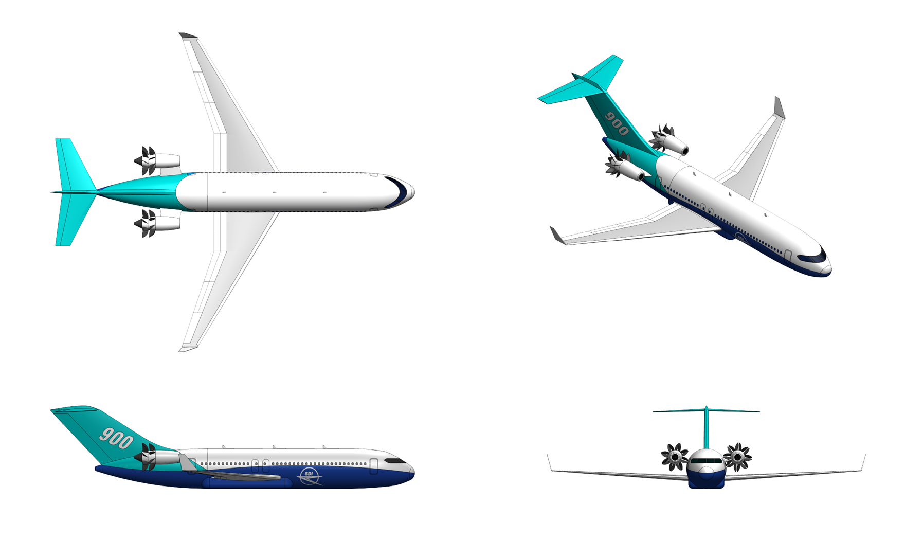

Overview:
The T 33 Pioneer is a carrier onboard delivery (COD) aircraft which is derived from SDI's S 5 Corsair carrier based anti-submarine aircraft. The aircraft is designed to ferry cargo and passengers to and from CATOBAR aircraft carriers such as SDI's own Inflictor class carrier.


Design & Construction:
The Pioneer employs shares the same basic fuselage and airframe as SDI's Corsair aircraft with the exception of a modified rear fuselage section which includes a rear loading ramp for loading and offloading cargo. Like the Corsair the Pioneer features an unconventional aerodynamic configuration with frontal all-moving canards, single folding vertical tail, and a large, high-aspect ratio folding wing located at the rear of the aircraft. Aft-loaded supercritical airfoils are used for both the wing and canard which minimize drag at high subsonic speeds. A large internal weapons bay sits between the wing and canards and is centered on the aircraft's center-of-gravity (cg). Control is provided by the control canards, inboard and outboard elevons on the wing, and a double-hinged rudder on the vertical tail. Two podded propfan engines are located at the midspan of each wing which employ a pusher propeller configuration which maximizes crew distance from the propfans to minimize noise inside the crew cabin as well as to provide passive protection for the crew and vital aircraft systems in case of blade failure.

The aircraft is constructed primarily from advanced composite materials in place of conventional aluminum. The airframe is primarily constructed from intermediate modulus graphite/epoxy and graphite/aramid composites which accounts for approximately 45% of the aircraft's dry weight. The fuselage is constructed from upper and lower skins of carbon-fiber reinforced polymer (CRFP) laminate which are manufactured out-of-autoclave and joined together using 3-dimensional woven performs infused with an epoxy resin to provide a rigid structural assembly without the use of fasteners. The wing and canards employ upper and lower stitched/RFI (Resin film infusion) manufactured CRFP skins with internal ribs and spars made from unidirectional prepreg carbon/epoxy tape using an automated fiber placement (AFP) process. The engine nacelles and control surfaces feature a honeycomb construction using carbon fiber-reinforced epoxy skins bonded to an epoxy resin-impregnated aramid honeycomb core.


Propulsion:
  • Name: SDI TPM430
  • Type: Three-shaft Propfan
  • Length: 3,780 mm
  • Diameter: 1,240 mm
  • Dry Weight: 1080 kg engine, 1,920 kg with propellor
  • Compressor: four stage LPC, four stage axial plus 1 stage centrifugal HPC
  • Combustor: annular counter-flow combustor
  • Turbine: single stage HPT, counter rotating single stage LPT, four stage PT
  • Maximum power output: 8,950 kW
  • Overall Pressure ratio: 34:1
  • Specific fuel consumption: 0.183 kg/kW-hr
  • Power-to-weight ratio:: 8.29 kW/kg
Like the Corsair the Pioneer is powered by two SDI TPM430 propfan engines each delivering 9,000 kW (12,000 shp) of sea-level static power and up to 70 kN of thrust at takeoff. The TPM430 is a three-spool, counter-rotating geared pusher propfan design. The high pressure spool employs four axial compressor stages with variable-inlet guide vanes (VIGVs) on the first compressor stage and one centrifugal compressor driven by a single-stage high pressure turbine. The low-pressure spool employs four axial compressor stages with twin variable stators driven by a single intermediate-pressure turbine. The twelve counter-rotating propeller blades (6 + 6) of each propfan engine are driven by a four-stage free power turbine through an in-line differential planetary gearbox with counterrotating output shafts which is cooled using fuel/oil and oil/air heat exchangers. The low-pressure compressor employs four Ti-6Al-4V titanium alloy blisk-rotors with a casing made from cast aluminum. The high-pressure compressor employs Ti-1100 (Ti-6Al-2.8Sn4Zr-0.4Mo-0.4Si) alloy titanium for the first three axial stage compressor blades, vanes, and disks and IN100 nickel-chromium superalloy for the last high-pressure compressor stage blades, vanes, and disk and for the centrifugal compressor. The high-pressure compressor casing made from cast 17-4 PH martensitic stainless steel around the axial section and IN100 alloy around the centrifugal stage. The combustor liners are manfactured from cast B1900+Hf nickel-hafnium superalloy with a casing made from cast IN100. The high pressure and intermediate pressure turbine blades and vanes are made from single-crystal IN718 nickel-chromium superalloy with a thermal barrier coating. The high pressure and intermediate pressure turbine blades feature combined convective and film cooling using high-pressure bleed air tapped off from the compressor. The high and intermediate pressure turbine disks as well as the power turbine blades, vanes, and disks employ cast IN713 nickel- chromium superalloy. Unlike the high and intermediate pressure turbines the power turbine stages do not feature any cooling. The turbine casing is made from cast IN100 alloy. The engine employs a multi-lobed mixer-ejector nozzle system which exhausts the hot air from the gas generator section of the engine through 11 equally spaced radial lobes located just forward of the propellor section. The lobed nozzle system facilitates highly effective mixing of the hot jet exhaust with cooler ambient air for reducing jet noise, lowering the engine's infrared signature, and reducing the temperature of the exhaust that impinges on the spinning propeller blades. The counter-rotating propellers with 6 blades each employ thin, highly swept propellor blades made from hollow superplastic forming and diffusion bonding (SPF/DB) titanium alloy spars with an outer fiberglass shell.

The TPM430 includes a dual-channel full authority digital electronic control system (FADEC). Control modes include independent control of blade pitch and propellor speed allowing variable synchrophasing control of each propfan engine to minimize engine noise and vibration, protective measures for regulating turbine-inlet temperature and preventing inadvertent engine overspeed or overtorque, and fault modes allowing for propellor blade feathering and gas generator compressor/turbine section windmilling if an engine fails or has to be shut down in flight. The FADEC control system is housed in a dual-channel electronic control unit containing circuitry connected to various engine sensors whose inputs are used by the FADEC system to control fuel flow, propeller pitch, variable compressor vanes and stators, bleed air flow, and other systems to optimize the performance of the engine throughout the flight envelope. Sensors are additionally linked together to the aircraft's control through a dual redundant fiber-optical data bank which integrates engine status and diagnostics with the aircraft's flight control system.


Avionics:
FMG 163 Weather Radar: The FMG 163 is an X band (9.375 GHz) 3D color weather radar which provides weather detection along with air-to-air detection and high-resolution ground mapping (HRGM) doppler beam sharpening precision ground mapping (PGM) synethic aperture radar (SAR) modes. The FMG 163 radar uses a solid state transmitter mounted on a to-axis gimbal in the nose of the aircraft with a maximum transmit power of 917 watts. Weather detection modes includes predictive wind shear (PWS), turbulence detection out to 110 kilometers, predictive lightning, predictive hail, and ​rain echo attenuation compensation technique (REACT) with the ability to automatically detect and avoid weather at ranges up to 600 kilometers from the aircraft. The FMG 163 also supports ground mapping capability with the ability to image terrain at ranges up to 150 kilometres from the aircraft with doppler beam sharpening providing X2 and X4 zoom modes for producing detailed imagery of terrain and geographical features.


Cockpit:
The Pioneer features a pressurized, fully 'glass' cockpit containing a crew of 3; a pilit, copilot, and a loadmaster. Both pilots are seated on zero/zero (zero altitude/zero speed) capable ejection seats. The tactical glass cockpit system is fully outfitted with an electronic flight instrument system (EFIS) and employs three 34 x 27 centimeter color LCD primary flight displays (PFDs) for the pilot and co-pilot.
Last edited by The Technocratic Syndicalists on Fri Feb 17, 2023 10:24 am, edited 12 times in total.
SDI AG
Arcaenian Military Factbook
Task Force Atlas
International Freedom Coalition


OOC: Call me Techno for Short
IC: The Kingdom of Arcaenia

User avatar
The Technocratic Syndicalists
Minister
 
Posts: 2346
Founded: May 27, 2015
Inoffensive Centrist Democracy

Postby The Technocratic Syndicalists » Sat Oct 09, 2021 5:17 pm

Image

A 11

General Characteristics:
  • Role: Carrier-based electronic reconnaissance aircraft
  • Crew: 4 (Pilot, Copilot/Naval Flight Officer, 2 System Operators)
  • Length: 20.4 m
  • Wingspan: 22.4 m
  • Height: 7.0 m
  • Wing area: 88.5 m2
  • Empty Weight: 19,800 kg
  • Fuel Weight: 8,400 kg
  • Max Takeoff Weight: 36,300 kg
  • Powerplant: 2x SDI TPM430 propfans, 9,000 kW each
  • Propellers: 16-bladed 2.8 m diameter counter-rotating (8-bladed forward, 8-bladed rear)
Performance:
  • Maximum Speed: Mach 0.75
  • Cruise Speed: Mach 0.70
  • Endurance: 8.0 hours @ 650 km radius
  • Ferry Range: 7,000 km
  • Service ceiling: 15,200 m
  • Wing loading: 362 kg/m2
  • Power/mass: 0.56 kW/kg
Avionics:
  • SDI FMB 330 ESM/ELINT System
  • SDI TKS 171 INS/GPS System
  • SDI RLG 640 Missile Approach Warning System
  • SDI FMB 790 Radar Warning Receiver System
  • SDI TKW 680 Countermeasures Dispenser System
  • SDI FMK 75 Fiber Optic Towed Decoy System


Overview:
The A 11 is a carrier-based electronic reconnaissance aircraft designed by SDI Aerospace Systems. The A 11 is a conversion of SDI Aerospace System's S 5 Corsair carrier based anti-submarine aircraft and contains a multi-function electronic intelligence (ELINT) and communications avionics suite in place of the Corsair's submarine detection avionics and weapons bay which is intended to support over-the-horizon maritime targeting, strike support, anti-submarine warfare, and suppression and destruction of enemy air defense missions.


Design & Construction:
The A 11 features an unconventional aerodynamic configuration with frontal all-moving canards, single folding vertical tail, and a large, high-aspect ratio folding wing located at the rear of the aircraft. Aft-loaded supercritical airfoils are used for both the wing and canard which minimize drag at high subsonic speeds. A large internal weapons bay sits between the wing and canards and is centered on the aircraft's center-of-gravity (cg). Control is provided by the control canards, inboard and outboard elevons on the wing, and a double-hinged rudder on the vertical tail. Two podded propfan engines are located at the midspan of each wing which employ a pusher propeller configuration which maximizes crew distance from the propfans to minimize noise inside the crew cabin as well as to provide passive protection for the crew and vital aircraft systems in case of blade failure.

The aircraft is constructed primarily from advanced composite materials in place of conventional aluminum. The airframe is primarily constructed from intermediate modulus graphite/epoxy and graphite/aramid composites which accounts for approximately 45% of the aircraft's dry weight. The fuselage is constructed from upper and lower skins of carbon-fiber reinforced polymer (CRFP) laminate which are manufactured out-of-autoclave and joined together using 3-dimensional woven performs infused with an epoxy resin to provide a rigid structural assembly without the use of fasteners. The wing and canards employ upper and lower stitched/RFI (Resin film infusion) manufactured CRFP skins with internal ribs and spars made from unidirectional prepreg carbon/epoxy tape using an automated fiber placement (AFP) process. The engine nacelles and control surfaces feature a honeycomb construction using carbon fiber-reinforced epoxy skins bonded to an epoxy resin-impregnated aramid honeycomb core.


Propulsion:
  • Name: SDI TPM430
  • Type: Three-shaft Propfan
  • Length: 3,780 mm
  • Diameter: 1,240 mm
  • Dry Weight: 1080 kg engine, 1,920 kg with propellor
  • Compressor: four stage LPC, four stage axial plus 1 stage centrifugal HPC
  • Combustor: annular counter-flow combustor
  • Turbine: single stage HPT, counter rotating single stage LPT, four stage PT
  • Maximum power output: 8,950 kW
  • Overall Pressure ratio: 34:1
  • Specific fuel consumption: 0.183 kg/kW-hr
  • Power-to-weight ratio:: 8.29 kW/kg
The A 11 is powered by two SDI TPM430 propfan engines each delivering 9,000 kW (12,000 shp) of sea-level static power and up to 70 kN of thrust at takeoff. The TPM430 is a three-spool, counter-rotating geared pusher propfan design. The high pressure spool employs four axial compressor stages with variable-inlet guide vanes (VIGVs) on the first compressor stage and one centrifugal compressor driven by a single-stage high pressure turbine. The low-pressure spool employs four axial compressor stages with twin variable stators driven by a single intermediate-pressure turbine. The twelve counter-rotating propeller blades (6 + 6)of each propfan engine are driven by a four-stage free power turbine through an in-line differential planetary gearbox with counterrotating output shafts which is cooled using fuel/oil and oil/air heat exchangers. The low-pressure compressor employs four Ti-6Al-4V titanium alloy blisk-rotors with a casing made from cast aluminum. The high-pressure compressor employs Ti-1100 (Ti-6Al-2.8Sn4Zr-0.4Mo-0.4Si) alloy titanium for the first three axial stage compressor blades, vanes, and disks and IN100 nickel-chromium superalloy for the last high-pressure compressor stage blades, vanes, and disk and for the centrifugal compressor. The high-pressure compressor casing made from cast 17-4 PH martensitic stainless steel around the axial section and IN100 alloy around the centrifugal stage. The combustor liners are manfactured from cast B1900+Hf nickel-hafnium superalloy with a casing made from cast IN100. The high pressure and intermediate pressure turbine blades and vanes are made from single-crystal IN718 nickel-chromium superalloy with a thermal barrier coating. The high pressure and intermediate pressure turbine blades feature combined convective and film cooling using high-pressure bleed air tapped off from the compressor. The high and intermediate pressure turbine disks as well as the power turbine blades, vanes, and disks employ cast IN713 nickel- chromium superalloy. Unlike the high and intermediate pressure turbines the power turbine stages do not feature any cooling. The turbine casing is made from cast IN100 alloy. The engine employs a multi-lobed mixer-ejector nozzle system which exhausts the hot air from the gas generator section of the engine through 11 equally spaced radial lobes located just forward of the propellor section. The lobed nozzle system facilitates highly effective mixing of the hot jet exhaust with cooler ambient air for reducing jet noise, lowering the engine's infrared signature, and reducing the temperature of the exhaust that impinges on the spinning propeller blades. The counter-rotating propellers with 6 blades each employ thin, highly swept propellor blades made from hollow superplastic forming and diffusion bonding (SPF/DB) titanium alloy spars with an outer fiberglass shell.

The TPM430 includes a dual-channel full authority digital electronic control system (FADEC). Control modes include independent control of blade pitch and propellor speed allowing variable synchrophasing control of each propfan engine to minimize engine noise and vibration, protective measures for regulating turbine-inlet temperature and preventing inadvertent engine overspeed or overtorque, and fault modes allowing for propellor blade feathering and gas generator compressor/turbine section windmilling if an engine fails or has to be shut down in flight. The FADEC control system is housed in a dual-channel electronic control unit containing circuitry connected to various engine sensors whose inputs are used by the FADEC system to control fuel flow, propeller pitch, variable compressor vanes and stators, bleed air flow, and other systems to optimize the performance of the engine throughout the flight envelope. Sensors are additionally linked together to the aircraft's control through a dual redundant fiber-optical data bank which integrates engine status and diagnostics with the aircraft's flight control system.


Avionics:
FMB 330 ESM/ELINT System: The primary avionics system of the A 11 is the FMB 330, a strategic grade passive electronic support measures (ESM) and electronic intelligence (ELINT) system which gives the aircraft the ability to detect, identify, and geo-locate radio frequency emissions at strategic ranges. The FMB 330 employs two wingtip antennas, a nose antenna, and a tail antenna to provide 360 degree coverage around the aircraft. Each of the four antenna feeds into an ultra-wide bandwidth photonic digital receiver which processes and analyzes the signal and compares to an on-board threat library for indentification. Identified signals are then sent through a fiber-optic LAN network to the aircraft's central mission computer where it is then displayed to the mission crew on their multifunction displays. Being a strategic grade system the FMB 330 has a sensitivity of -90 to -95 dBm and covers the 0.02-40 GHz frequency system with a 40 GHz instantaneous bandwidth. The dual baseline interferometry techniques used by the system and the wide spacing of the antenna allow DF accuracy to within 1°RMS. The system is able to detect and track up to 1,000 simultaneous radar threats including conventional pulse-Doppler and continuous wave (CW) as well as LPI/LPD (Low Probability of Intercept/Low Probability of Detection) radars employing frequency-modulated continuous wave (FMCW) operating modes. The sensitivity of the FMB 330 system permits the detection of a 100 watt vehicle APS radar at 400 kilometers and a 10 kilowatt fighter aircraft radar at over 1,000 kilometers (radar horizon limited). The FMB 330 is used to generate a real time electronic order of battle (EOB) where all threat emitters and other hostile RF sources in a given area of operations are continuously detected, categorized, and geolocated in an electronic file which is disseminated to theater commands and continuously updated in real time.

TNS 171 INS/GPS System: The TNS 171 is a combined inertial navigation system and global positioning system (INS/GPS) which provides autonomous long-range navigation capability for the aircraft. The TNS 171 combines dual 6-axis strap-down inertial measurement units (IMU) with three fiber-optic gyroscopes (FOG) and three-axis solid-state silicon micro electro-mechanical system (MEMS) accelerometers each with a 24 channel, Selective Availability/Anti-Spoofing Module (SAASM) based zero-age differential global positioning system (ZDGPS) anti-jam GPS receiver system. GPS only, INS only, and blended GPS/INS navigation modes are available with the TNS 171 navigation system.

RLG 640 Missile Approach Warning System: The RLG 640 is a passive missile warning system installed in the aircraft which provides warning of incoming threat missiles. The RLG 640 system employs four optical sensor heads with integral optical signal converters mounted in the nose and tail cone of the aircraft which provide combined 360 degree azimuth coverage, a central processor which inputs and analyses signals from the four sensor heads to detect and classify threats, and a central control unit located in the cockpit which provides visual and aural threat warning to the crew and allows for control of the system. Each RLG 640 sensor heads contains an ultra-violet (UV) single-pixel quadrant sensors with an adjunct UV sensor for improved dynamic blanking, a laser warning sensor, and a multi-color short-wave infrared (SWIR) camera which provide detection and tracking of incoming missiles and rockets and warns the crew when the aircraft is being illuminated by a laser designator/illuminator/rangefinder or if the aircraft is being targeted by a laser beam-riding missile. An additional hostile-fire indicator (HFI) capability provides detection of muzzle flashes and detection and tracking of incoming tracer projectiles fired at the aircraft. An interface with the aircraft's radar warning system allows the RLG 640 system to distinguish between radar and infrared guided missile threats and to automatically queue the countermeasures system to dispense flares when the system identifies an oncoming IR guided missile.

FMB 790 Radar Warning Receiver System: The FMB 790 Radar Warning Receiver is a digital radar warning system which alerts the crew the aircraft is being illuminated by a threat radar. The FMB 790 provides 360 detection of radar signals in the 0.5-40 MHz range and employs two 2-20 Mhz and two 2-40 MHz spiral antenna and a 0.5- 2 MHz blade antenna which feed into four wideband superheterodyne digital quadrant receivers connected to a electronic warfare processor. The FMB 790 system continuously detects and intercept RF signals including both continuous wave and pulse-doppler around the aircraft and displays threat signals to crew on a cockpit display unit along with warning tones which warn the crew when the system detects the aircraft is being illuminated by a hostile radar. Data from the FMB 790 system is automatically transmitted to the aircraft's TKW 680 countermeasures dispenser system which can be set to automatically disperse chaff and expendable active radar decoys when the FMB 790 system detects the aircraft is being targeted by radar guided missiles.

TKW 680 Countermeasures Dispenser System: The TKW 680 is an airborne countermeasures dispenser system designed to dispense chaff, flares, and other expendable decoys to increase aircraft survivability. The TKW 680 system consists of multiple tail mounted cartridge dispenser modules (CDMs) each capable of containing up to 32 5.0 cm x 2.5 cm x 8.0 cm countermeasures each and a central defensive aids controller (DAC) unit with inputs from both the missile/laser warning system and RWR system. When a threat missile is detected by the aircraft's missile/laser warning system or RWR systems the defensive aids controller of the TKW 680 automatically selects appropriate expendable countermeasures to be released by the system's dispensers to decoy or spoof away the incoming missile. Countermeasures supported including pyrophoric spectral flares for decoying IR missiles and chaff, and active digital radio frequency memory (DRFM) decoys for decoying RF guided missiles.

FMK 75 Fiber Optic Towed Decoy System: The FMK 75 is a radio-frequency towed decoy system which when integrated with the aircraft's FMB 229 electronic countermeasures system is intended to suppress and/or deceive hostile radar systems to prevent them from acquiring ad tracking the host aircraft. The FMK 75 system employs a towed decoy equipped with dual high-power traveling wave tubes (TWT) based jammers designed to counter coherent pulse-Doppler and continuous-wave (CW) radars and is connected to the host aircraft using a fiber-optic line. Two reel-in/reel-out deployed units are located underneath the aircraft's wingtip ECM pods and are capable of deploying and reeling back in the decoys during flight as necessary. RF threats are detected and analyzed by the aircraft's FMB 229 ECM system which then sends an appropriate jamming signal through the fiber-optic line to the towed jammer through an electronic frequency converter (EFC) which converts the RF signals from the planes ECM suite into optical signals which are transmitted through the fiber-optic line. The signals are the converted back to RF using an electronic frequency converter on the decoy unit where the towed decoy then emits the jamming waveform to prevent or impede the hostile radar's ability to track the aircraft.


Cockpit:
The A 11 features a pressurized, fully 'glass' cockpit containing a crew of four seating facing forward in a 2 by 2 arrangement. The pilot sits in the left forward seat, the co-pilot/naval flight operator in the right forward seat, and two systems operators in the two rear seats. All four crew are seated on zero/zero (zero altitude/zero speed) capable ejection seats. The tactical glass cockpit system is fully outfitted with an electronic flight instrument system (EFIS) and employs three 34 x 27 centimeter color LCD primary flight displays (PFDs) for the pilot and co-pilot. The two rear seats employ interchangeable SDI multi-function display/control system (MFDCS) crew stations with 51 cm multi-function color LCD displays.
Last edited by The Technocratic Syndicalists on Fri Mar 13, 2026 2:10 pm, edited 8 times in total.
SDI AG
Arcaenian Military Factbook
Task Force Atlas
International Freedom Coalition


OOC: Call me Techno for Short
IC: The Kingdom of Arcaenia

User avatar
The Technocratic Syndicalists
Minister
 
Posts: 2346
Founded: May 27, 2015
Inoffensive Centrist Democracy

Postby The Technocratic Syndicalists » Thu May 19, 2022 7:25 pm

Image

D 19 Osprey

General Characteristics:
  • Role: Reconnaissance UAV
  • Crew: none
  • Length: 2.5 m
  • Wingspan: 4.8 m
  • Height: 0.67 m
  • Empty weight: 34 kg
  • Fuel weight: 10 kg
  • Payload weight: 18 kg
  • Max takeoff weight: 60 kg
  • Powerplant: 1x 8.0 PS (5.9 kW) multi-fuel engine, 4x quadrotors
Performance:
  • Maximum speed: 90 knots
  • Cruise speed: 60 knots
  • Maximum range: 1,500 km
  • Endurance: 16 hours
  • Service ceiling: 6,000 m
Payload:
  • EOS 280 gimballed EO/IR sensor


Overview:
The D 19 Osprey is a tactical vertical take off and landing (VTOL) capable UAV designed by SDI Aerospace systems. The Osprey provides organic intelligence, Surveillance, and Reconnaissance (ISR) capability to tactile units and is designed for missions including target locating and tracking, maritime target identification, shore reconnaissance, helicopter landing zone reconnaissance, area and route reconnaissance, convoy overwatch, and riverine and small craft transit over-watch. The complete D 19 system consists of four vehicles with electro-optical/infrared and communications relay payloads, two ground control stations each with two operator workstations, and four ground data terminals. The D 19 drones feature a modular construction and can be broken down into small and easily assembled line replaceable units for transport. The Osprey vehicle is specifically designed for operations from moving vessels in rough seas, providing a ship-based ISR that can deploy without catapults, arresting gear, or dedicated launch/recovery equipment.


Design & Construction:
The Osprey features a twin-boom, low-wing, pusher-propeller configuration which has proven to be the optimal layout for hybrid VTOL fixed-wing tactical UAS. The configuration places the combustion engine and pusher propeller at the aft of the fuselage with the VTOL lift motors on boom-mounted nacelles with two booms extending aft from the wing, each carrying two electric motor/rotor assemblies, the payload bay in the forward fuselage, and the avionics and fuel tank in the center fuselage. The twin-boom arrangement provides a clean aerodynamic configuration with the lifting surfaces unobstructed by the propulsion system, structural rigidity through the boom-wing-fuselage box structure, natural mounting points for the VTOL rotors well separated from the center of gravity, and an inverted-V tail at the boom junction for pitch and yaw control.

The airframe of the Osprey is a composite monocoque construction using carbon fiber reinforced polymer (CFRP) skins over a Nomex honeycomb core, providing an exceptional strength to weight ratio while resisting the corrosive effects of the marine environment. All metallic components including fasteners, hinges, arebrackets are either titanium or marine-grade stainless steel to prevent galvanic corrosion in salt spray environments. The wing is a low-wing configuration with a constant-chord center section and outer panels, providing a total wing area of approximately 1.4 square meters. The wing uses a custom low-Reynolds-number airfoil optimized for cruise at 50 to 60 knots. Wing loading at MGTOW is approximately 60 kg/m², providing good gust handling and low stall speed of approximately 30 knots. The outer wing panels fold inward for transport and storage, reducing the packed wingspan to approximately 2.0 meters. The fuselage has a streamlined, semi-circular cross-section approximately 300 mm wide × 250 mm tall. The forward section houses the gimbal bay with a ventral opening for the underslung gimbal, modular payload bay, and avionics. The center section houses the fuel tank. The aft section houses the heavy fuel engine, engine accessories, exhaust system, and the pusher propeller. The twin booms extend approximately 1.5 meters aft from the wing trailing edge and are constructed from CFRP tube construction with internal wire routing for VTOL motor power and control. Each boom carries two VTOL motor/rotor nacelles, one forward and one aft, providing a total of four VTOL lift points arranged in a rectangular planform for maximum stability. The tail is ann inverted-V tail connects the boom tips, providing both pitch and yaw control through two ruddervators. The inverted-V configuration provides ground clearance during VTOL operations and protects the tail surfaces from damage during shipboard operations.

The Osprey breaks down into six major modules for transport including the fuselage assembly (with avionics, fuel system, and engine installed), left and right wing panels (each with one boom and two VTOL nacelles), tail assembly, gimbal payload, and battery pack. A two-person crew can assemble the vehicle from transit cases in approximately 25–30 minutes. The system packs into three ruggedized transit cases (two for the vehicle, one for the ground control station and support equipment), with a total transport weight of approximately 180 kg or the complete system.


Propulsion
  • Type: Piston engine
  • Length: 145 mm
  • Width: 240 mm
  • Height: 70 mm
  • Dry Weight: 5.3 kg
  • Configuration: 2-cylinder boxer
  • Bore: 44 mm
  • Stroke: 34 mm
  • Displacement: 100 cc
  • Rated power: 8 PS (4.0 kW) @ 6,500 RPM
  • Specific fuel consumption: 350 g/kW-hr
The Osprey features a hybrid quadcopter propulsion system with four battery driven brushless DC rotors for vertical thrust and a propeller driven by a 2-stroke heavy fuel engine (HFE) for horizontal thrust. In horizontal flight the aircraft is powered by a 2-cylinder multi-fuel boxer engine which direct drives a three blade fixed pitch pusher propellor. The engine includes an integral 0.5 kW 28 VDC starter/generator unit which starts the engine and provides electrical power to the aircraft during flight. During cruise flight, the VTOL rotors are stopped and their blades feathered to minimize drag. During VTOL operations, the cruise engine is idled orshut down. This separation ensures that the cruise engine is optimized purely for efficient forward flight while the VTOL system is optimized for high power density and rapid response, and a failure in either system does not immediately compromise the other, the vehicle can fly on the cruise engine if VTOL motors fail during cruise, and can complete a VTOL landing on the electric system if the engine fails.

The cruise propulsion engine is a heavy-fuel, multi-fuel internal combustion engine. The engine drives a three-blade, variable-pitch composite propeller in a pusher configuration. Variable pitch provides optimized efficiency across the speed range and enables aerodynamic braking during VTOL transitions. The propeller is designed with low-noise blade profiles including swept tips and optimized chord distribution to minimize the acoustic signature during cruise flight. The four VTOL lift motors are direct-drive brushless permanent magnet motors, each driving a two-blade folding composite rotor of approximately 550 mm diameter. The motors are mounted in pairs on each wing boom, with approximately 1.5 meters separation between forward and aft motors on each boom and approximately 3.0 meters separation between left and right booms. Each motor produces approximately 25 kgf of static thrust at maximum power, providing a total VTOL thrust of approximately 100 kg, a thrust-to-weight ratio of approximately 1.2:1 at MGTOW which provides adequate margin for maneuvering and gust rejection during VTOL operations. Each motor produces a continuous power of approximately 2 kW each with a peak power for VTOL operations of approximately 4 kW each. The four VTOL motors are powered by a dedicated lithium-polymer battery pack mounted in the fuselage center section. Battery capacity is approximately 1,500 Wh (44.4V, 34 Ah), weighing approximately 8 kg. This capacity provides approximately 8 to 10 minutes of total VTOL hover time, sufficient for multiple takeoffs and landings during a single mission, with reserve. During cruise flight, the battery can be trickle charged from the engine's starter-generator, ensuring full charge is available for landing after extended missions. In emergency situations, the VTOL system can sustain controlled flight for a safe landing even if the cruise engine fails.

The Osprey operates in three flight modes. In VTOL Mode all four VTOL motors run at high power while the vehicle is hovering or maneuvering vertically. The cruise engine is idlied or stopped. The flight controller manages attitude and position using differential thrust across the four motors. This mode is used for takeoff, landing, and any hover operations. After VTOL takeoff, the vehicle pitches forward to accelerate while the VTOL motors continue to provide lift. As airspeed increases and the wing begins to generate aerodynamic lift, the VTOL motor power is gradually reduced. At approximately 30 to 35 knots the VTOL motors are shut down and the blades fold or feather to reduce drag. The cruise engine simultaneously ramps up to cruise power. The reverse transition occurs before landing. The flight control computer manages the entire transition sequence automatically, the operator simply commands "go to point" and the vehicle handles all mode changes. In cruise mode the vehicle is in wing-borne flight powered by the cruise engine, with the VTOL motors stopped and folded. The vehicle flies like a conventional fixed wing aircraft, controlled by conventional aerodynamic surfaces including the ailerons and ruddervators which are actuated by electromechanical servos.

The Osprey vehicle's flight controller incorporates a dedicated ship-relative navigation and control mode specifically designed for maritime VTOL operations: During the approach to the ship, flight computer fuses data from multiple sources to build a real-time model of the ship's motion. The vehicle's RTK-GPS and the ship's RTK-GPS (transmitted via datalink) provide the relative position between vehicle and ship to centimeter-level accuracy. The vehicle's downward-looking optical flow camera and laser altimeter measure the vehicle's position and height relative to the deck in the final meters of approach. An onboard Kalman filter estimates the ship's heave, surge, sway, roll, pitch, and yaw in real time, predicting the deck position 1–3 seconds into the future. Predictive Landing: Rather than trying to match the deck's motion continuously (which would require infinite control bandwidth), the flight control system uses a predictive approach, identifying the periodic component of the deck motion (dominated by the wave encounter frequency), predicts the next "quiescent period" (the moment when the deck is near the center of its motion envelope and moving slowly), and times the final descent to arrive at the deck during this window. The landing sequence proceeds in phases. The vehicle first transitions from cruise to VTOL mode at a safe altitude approximately 50 meters above the ship. It then enters a station-keeping hover approximately 20 meters above and 30 meters abeam the ship, matching the ship's heading and speed while the ship motion estimator builds its model. It then translates laterally to a position directly above the designated landing point on the ship's deck, maintaining station-keeping in the ship-relative frame. It then descends at a controlled rate, with the final 5 meters of descent timed to coincide with the predicted quiescent period. Upon touchdown, the VTOL motors immediately cut to idle and mechanical deck locks (if equipped) or friction pads engage to prevent the vehicle from sliding. The Osprey is designed to conduct autonomous VTOL operations from vessels with helicopter flight decks in sea states up to Sea State 5 (significant wave height 2.5–4.0 meters) during daylight, and Sea State 4 at night or in reduced visibility.


Avionics:
SDI NEXUS Flight Autonomy Software: The Osprey integrates a scaled variant of the SDI's NEXUS Autonomous Flight Control Suite. The Nexus Flight Control tier runs on a dual-redundant flight controller that manages inner-loop attitude control, navigation, engine management, VTOL motor control, and transition logic. The controller runs at 400 Hz and incorporates a tactical-grade MEMS IMU, dual-redundant GPS receivers, barometric altimeter, magnetometer, air data system (pitot-static for airspeed and altitude), radar altimeter (for precision height above ground/deck during VTOL operations), and downward-looking optical flow camera (for precision position hold during VTOL). The Nexus Mission Autonomy tier uses an SDI Lattice AI computing module which provides the AI inference capability for autonomous mission planning and execution. This partition runs the mission behavior models, processes gimbal imagery for automatic target detection and classification (via the SPOTR-equivalent ATR neural network), manages the multi-spectral sensor suite (selecting optimal spectral bands and zoom settings based on target type, range, and atmospheric conditions), and coordinates with external systems. The ground control station is a ruggedized laptop with dedicated radio interface, plus an optional larger multi-screen console for shore-based or shipboard operations and runs the NEXUS mission planning and monitoring interface.

NEXUS provides several autonomous mission capabilities beyond basic autopilot functions. Given a mission objective (e.g., "surveil area X"), NEXUS automatically generates an optimal route considering terrain, known threat locations, weather, airspace restrictions, and fuel constraints. The route is re-planned dynamically if new threats are detected or weather conditions change. During surveillance operations NEXUS automatically selects the optimal sensor channel and zoom level based on the current task. For wide-area search, it uses the EO channel in wide field of view. When a contact is detected, it automatically zooms in and cross-cues the MWIR channel for thermal confirmation. In haze or smoke, it switches to SWIR. At night, it uses MWIR as the primary channel with SWIR as a supplement. For designation, it activates the laser designator and confirms spot placement on the SWIR channel. This adaptive behavior reduces operator workload and ensures the optimal sensor is always in use. Autonomous Target Acquisition and Tracking: NEXUS's integrated Sentient AI processing software processes all three imaging channels simultaneously, fusing detections across spectral bands to improve detection probability and reduce false alarms. NEXUS also supports coordinated operations between multiple Ospreys and other NEXUS equipped platforms. A single operator can manage 2 to 3 Ospreys simultaneously, with NEXUS automatically deconflicting flight paths, distributing sensor coverage, and handing off tracked targets between platforms. When supporting ground forces or naval fire support, NEXUS can execute autonomous designation sequences: acquiring the target, confirming identification (with human authorization), activating the laser designator with the correct code, maintaining stable designation throughout the weapon's time of flight, and performing automatic battle damage assessment using the imaging sensors after impact.

EOS 280: The Osprey is equipped as standard with an SDI EOS 280 electro-optical sensor turret system. The EOS 280 is a 4-axis gyro-stabilized multi-spectral electro-optical/infrared gimbal housed in the forward fuselage bay, providing simultaneous imaging across three spectral bands plus active laser designation and ranging. The gimbal houses five co-boresighted optical channels sharing a common 200 mm aperture window. The High-Definition Electro-Optical (HD EO) channel consists of a 1920 × 1200 pixel global shutter CMOS sensor with a continuous zoom lens providing 30× optical magnification with field of view from 40° wide to 1.3° narrow. The sensor operates across the visible spectrum (400–900 nm) with automatic gain control, electronic image stabilization, and real-time H.265 encoding at up to 1080p60. Detection, recognition, and identification (DRI) ranges against a 2.3 × 2.3m vehicle target are detection ay approximately 25 km, recognition at approximately 12 km, and identification at approximately 7 km. The Mid-Wave Infrared (MWIR) channel employs a cooled indium antimonide (InSb) focal plane array with 1280 ×1024 pixel resolution at 15 μm pixel pitch, operating in the 3–5μm range. The detector is cooled by a miniature Stirling-cycle cryocooler to approximately 77 K. The MWIR channel features a continuous zoom lens with 12× optical magnification with field of view from 20° wide to 1.7 ° narrow). DRI ranges against a 2.3 × 2.3m vehicle target are detection at approximately 18 km, recognition at approximately 9 km, and identification at approximately 5 km. The Short-Wave Infrared (SWIR) channel employs an InGaAs (indium gallium arsenide) focal plane array with 1280 × 1024 pixel resolution at 12.5 μm pixel pitch, operating across the 0.9–1.7 μm spectral band. The SWIR detector operates at ambient temperature (uncooled), eliminating the need for a second cryocooler. The SWIR channel features a continuous zoom lens with 15× optical magnification. The laser designator consists of a diode-pumped solid-state laser operating at 1064 nm, providing coded laser designation for guidance of laser-guided munitions. The designator produces a spot at ranges up to 10 km with coding capability for multiple simultaneous designations. The designator operates in pulsed mode with adjustable pulse repetition frequency (PRF). The SWIR channel can image the designator spot, providing real-time confirmation that the designation is on target. The laser rangefinder (LRF) is an n eye-safe (1550 nm) pulsed laser rangefinder providing range measurements to targets at distances up to 120 km with a range accuracy of ±1 meters. The LRF data is used along with gimbal IMU/GPS data to provide geopointing/geolocation capability, enabling the system to compute target coordinates with a circular error probable (CEP) of approximately 5 to 10 meters at typical engagement ranges. The laser pointer/illuminator is a dual-mode laser operating at 830 nm (near-infrared) and optionally at 532 nm (visible green) for marking targets or points of interest for ground forces. The pointer is compatible with standard military night vision equipment and provides a visible aiming reference for cooperative ground-air operations. he gimbal employs a three-axis (azimuth, elevation, roll) direct-drive stabilization system using frameless brushless DC torque motors and high-resolution optical encoders on each axis. Inertial stabilization is provided by a fiber-optic gyroscope (FOG) triad integrated within the gimbal housing. The stabilization system achieves a line-of-sight (LOS) jitter of 5 to 10 µrad RMS. The gimbal provides continuous 360° azimuth rotation and +20° / -120° elevation coverage with a 60°/s slew rate. Geo-pointing and geo-stabilization modes allow the operator to designate a ground coordinate and maintain sensor boresight on that location regardless of aircraft maneuvering.

To support automatic target recognition capability the EOS 280 runs SDI's "Sentient" AI-powered object detection and tracking software which detects and identifies targets and other objects of interest in the the electro-optical sensor feed. The system runs on the air vehicle's SDI Lattice GPGPU AI supercomputer with 275 TOPS of INT8 performance. The machine learning algorithms used by Sentient are trained on a library of multispectral data for both search characteristics and feature extraction and detects both stationary and moving objects which on land include vehicles, people, and weapon systems in complex terrain and environments. Sentient is capable of detecting objects as small as 2x2 pixels with persistent tracking functionality that separate tracks for each detected object even when they overlap or pass behind temporary obstructions. The processed video and metadata stream from Sentient is output to both the NEXUS computing partition for AI-driven situational awareness and autonomous decision-making and the communications system for transmission to the ground control station. Additional features enabled by Sentient include image registration capability that automatic aligns the thermal and EO sensor feeds to compensate for parallax and time sync differences, blind and semi-blind deblurring methods that use estimated point spread functions (PSF) to counteract atmospheric and motion blur, radial and tangential lens dewarping, thermal dehazing functions designed to mitigate the effects of haze, smoke, and dust by employing local adaptive compensation for atmospheric particle dispersion, and image blending of thermal and visible channels that automatically adjusts blending factor for day and night and local weather conditions, and sensor fusion of thermal and visible channels.

Communications: The Osprey carries a multi-band digital communications suite providing redundant data paths for vehicle control, payload data, and situational awareness. The primary Line-of-Sight (LOS) datalink is SDI's Ku band (14.40-14.93 transmit and 15.15-15.35 GHz receive) tactical high bandwidth datalink (THBD) system which uses a narrow-band 200 kbps uplink for vehicle, sensor, and armament control and and a wide-band 45 Mbps downlink to transmit FLIR or radar imagery from the aircraft back to the control station. The LOS link carries full-motion video from all three gimbal channels, vehicle telemetry, and command uplink. The link uses AES-256 encryption, frequency hopping, and adaptive modulation to operate in contested electromagnetic environments. Secondary LOS datalink is a C-band (5.0 GHz) backup datalink providing lower-bandwidth communication (sufficient for compressed video from one channel plus telemetry) at extended range. This link serves as a backup if the primary Ku band link is jammed or attenuated. A Ka-band SATCOM terminal mounted in a conformal fuselage antenna enables operations beyond the LOS datalink range, providing global connectivity via military or commercial satellite networks. An integrated software-defined radio (SDR) provides the ability to relay communications between ground forces and the GCS (acting as an airborne communications relay), receive situational awareness dat, and broadcast target location data directly to fire support systems.
Last edited by The Technocratic Syndicalists on Thu May 14, 2026 10:22 am, edited 3 times in total.
SDI AG
Arcaenian Military Factbook
Task Force Atlas
International Freedom Coalition


OOC: Call me Techno for Short
IC: The Kingdom of Arcaenia

User avatar
The Technocratic Syndicalists
Minister
 
Posts: 2346
Founded: May 27, 2015
Inoffensive Centrist Democracy

Postby The Technocratic Syndicalists » Thu Feb 16, 2023 7:25 pm

Image


S-1400

General Characteristics:
  • Role: Regional airliner
  • Crew: 2 pilots
  • Seating:
      2-class: 96(12J + 84Y)
      1-class: 108 (108Y)
      Exit limit: 145
  • Length: 31.9 m
  • Wingspan: 28.8 m
  • Height: 8.75 m
  • Wing area: 92 m2
  • Empty Weight: 24,000 kg
  • Fuel Weight: 12,000 kg
  • Max Payload: 12,000 kg
  • Max Takeoff Weight: 40,600 kg
  • Powerplant: 2x SDI TPM600 Propfan engines, 9,000 kW each
Performance:
  • Maximum Speed: Mach 0.78
  • Cruise Speed: Mach 0.74
  • Range: 3,000 km (standard), 4,800 km (w/ center fuel tank)
  • Service ceiling: 12,000 m
  • Wing loading: 571 kg/m2
  • Takeoff length: 780 m
  • Landing length: 760 m


Overview:

The S-1400 is an advanced propfan regional airliner signed by SDI designed to improvements in fuel efficiency, operating economics, runway performance, and community noise impact relative to current-generation regional turbofan powered aircraft. The aircraft is designed to carry 90 to 100 passengers in a two-class cabin layout with a comfort standard equivalent to current narrowbody airliners, over a design range of 3,000 km with maximum payload and an extended range capability of 4,800 km with a reduced passenger load. The S-1400 is produced jointly by SDI and by Aeronox of The Macabees who owns a 25% workshare of the S-1400 program and are responsible for producing a variety of the aircraft's subsystems and the majority of the aircraft's structure including the wings and several of the fuselage sections at their plant in Macabea. Final assembly of all S-1400's occurs at SDI's Isenstadt plant in Isenstadt, Arcaenia


Design & Construction:
The S-1400 features a high-wing, T-tail configuration with two wing-mounted tractor propfan engines The high wing permits unobstructed exhaust flow from the IBF system beneath the trailing edge, provides favorable ground clearance for the large-diameter propfan rotors, and positions the propulsion system above and forward of the cabin for noise shielding. The T-tail moves the horizontal stabilizer clear of both the propeller slipstream and the wing wake, improving longitudinal control power and reducing buffet. The fuselage cross-section is a circular-section pressure vessel with an external diameter of 3.95 m, sized to accommodate five-abreast economy seating at a 46 cm seat width with a single center aisle of 51 cm. Overall fuselage length is 31.5 m. The primary structures of the wing and fuselage are constructed from graphite/epoxy composites using SDI's proprietary ICARUS (Innovative Composite Architecture for Reliable Unitary Structures) composite manufacturing technology. ICARUS uses seamless co-cured structural panels formed through-thickness stitching of dry composite preforms which are resin infused using controlled atmospheric pressure resin infusion (CAPRI) and then cured in an out-of-autoclave process to create large, highly structurally efficient and damage tolerant composite structures which eliminate the need for mechanical fasteners and have significantly reduced part counts and fabrication and assembly times compared to conventional composite structures. ICARUS composite panels contain carbon fibers that are pre-kitted in multi-ply stacks with a 44/44/12 percent distribution of 0, 45, and 90° plies that are are used to build up the desired thickness and configuration. The panels are bi-directionally stiffened using unidirectional pultruded carbon rods to provide structurally efficient stiffening in one direction while foam-filled frames are positioned perpendicular to the rod-stiffeners to provide stiffening in the other direction. All stiffener flanges are stitched to the skin and no mechanical fasteners are used for joining. The integral stiffeners increases the structurally efficiency of each panel while the use of stitches instead of fasteners provides significantly more damage tolerance. ICARUS panels are created and cured entirely at atmospheric pressure and temperature, eliminating the need for curing ovens and autoclaves and allowing significantly larger composite structures to be created compared to legacy composite manufacturing methods. The fuselage is divided into a forward passenger cabin section, a center wing carry-through section, and an aft cabin and empennage section. The forward fuselage houses the cockpit, forward galley, lavatory, and 12 business-class seats at a 92 cm pitch in a 2+2 configuration. The main economy cabin provides 84 seats at a 79 cm pitch in a 3+2 configuration, giving a total two-class capacity of 96 passengers. A single-class configuration at 81 cm pitch accommodates 108 passengers. The lower deck houses containerized baggage and cargo compartments, with a forward compartment accepting four LD3-45 containers and an aft bulk cargo hold. Total underfloor cargo volume is 16.8 cubic meters. Fuselage structural design incorporates a cabin differential pressure of 63.4 kPa, permitting a cabin altitude of 1,800 m at the maximum cruise altitude of 12,000 m. The ICARUS panel construction enables a frame pitch of 610 cm and a stringer pitch of 15 cm, both wider than comparable metallic structures, reducing part count and weight.

The S-1400 wing is a low-sweep, high-aspect-ratio design optimized for cruise efficiency in the Mach 0.72–0.75 regime while providing sufficient internal volume for fuel storage and structural depth for the ICARUS wing box. The wing planform features a simple taper with a low leading-edge sweep angle of 10°. This reduced sweep provides a significant benefit in usable maximum lift coefficient (approximately 11% higher than a conventional 28° swept wing) while also reducing wing structural weight and manufacturing complexity. The wing box primary structure employs ICARUS construction for the upper and lower cover panels, with stitched composite spars and ICARUS compatible rib structures. The wing box extends from approximately 15% chord to 65% chord, providing adequate volume for integral fuel tanks and structural depth. The ICARUS wing covers use pultruded rod stiffeners oriented spanwise, with through-thickness stitching providing damage tolerance and post-buckling strength. The wing employs supercritical airfoil sections optimized for the cruise Mach number of 0.74. The root airfoil is a 14% thick section with a design lift coefficient of 0.50, transitioning to an 11% thick section at the tip. The airfoil sections are tailored to maintain natural laminar flow over the forward 25–30% of the upper surface at cruise conditions, contributing to a reduction in profile drag. The low wing sweep enables higher usable lift coefficients before sweep-induced spanwise flow causes premature boundary layer separation, which is critical for the short-field performance enabled by the IBF high-lift system. At the design cruise condition of Mach 0.74 at 10,600 meter altitude, the wing achieves a cruise lift-to-drag ratio of approximately 15. The S-1400 employs a T-tail arrangement with the horizontal tailplane mounted at the top of the vertical stabilizer. This configuration positions the horizontal stabilizer above and aft of the propfan slipstream for improved longitudinal control effectiveness, moves the horizontal tail out of the wing downwash field for reduced trim drag, an provides favorable deep-stall recovery characteristics when combined with the high-wing configuration and ventral strake. Both the horizontal and vertical stabilizers employ PRSEUS composite construction. The elevator provides a maximum deflection range of +20/−25°, and the rudder deflects ±30°. Both control surfaces are split into inboard and outboard segments for redundancy.

The S-1400 features a conventional tricycle landing gear arrangement with a twin-wheel steerable nose gear and two twin-wheel main gear units. The main gear retracts forward into bays located in the fuselage lower structure beneath the wing carry-through box, a configuration necessitated by the high-wing arrangement that precludes conventional wing-mounted gear stowage. The nose gear retracts aft into a bay beneath the cockpit floor. The main gear is designed for a maximum sink rate of 3.05 m/s at maximum landing weight and incorporates oleo-pneumatic shock absorbers with a stroke of 42 cm. The tire size is 1,050 × 395 mm at a pressure of 1.10 MPa, selected for compatibility with the low-strength pavement surfaces typical of the smaller regional airports that the S-1400 is intended to serve. Carbon-carbon ceramic matrix composite brake units with anti-skid control are fitted to all main wheels. A ground-fine pitch propeller capability provides additional deceleration during landing rollout, reducing brake wear and enabling consistent short-field landing performance on contaminated runways.


Vehicle Management System & Flight Control Surfaces:
Vehicle Management System (VMS): The S-1400 fly-by-wire system is managed by four vehicle management computers (VMCs), organized as two pairs. VMCs 1 and 2 are the primary pair (command channels), and VMCs 3 and 4 are the secondary pair (monitor and backup channels). The primary VMCs are implemented using dissimilar hardware architectures (VMC1 uses a PowerPC-based processor, VMC2 uses an ARM-based processor). The secondary VMCs provide a simplified, independently certified control law (direct law with stability augmentation) as a reversionary mode in the event of dual primary VMC failure. The VMCs receive inputs from quadruple-redundant air data and inertial reference systems (ADIRS), triple-redundant pilot side-stick controllers (force-sensing, non-moving), and triple-redundant rudder pedal assemblies. The S-1400 FBW system implements three control law modes: Normal Law (full envelope protection, C*U speed stability, bank angle hold, automatic pitch trim, alpha and load factor limiting, and automatic coordination of VC/DFS with flight controls), Alternate Law (reduced envelope protection, engaged automatically upon single VMC failure or partial sensor loss), and Direct Law (proportional stick-to-surface commands with basic stability augmentation, engaged upon dual primary VMC failure, using the secondary VMCs). Normal Law also incorporates automatic gust load alleviation using the spoilers and DFS system, reducing wing bending loads during turbulence encounters and allowing a lighter wing structural design. The control laws are designed for carefree handling throughout the flight envelope, with hard protections against stall, overspeed, over-g, and over-bank that cannot be overridden by the pilot in Normal Law.

Control surfaces: Primary pitch control is provided by the split elevator on the horizontal tailplane, with each half driven by two independent hydraulic servo actuators powered by different hydraulic systems. Roll control at cruise speeds uses conventional ailerons on the outboard wing, supplemented by differential IBF blowing at low speeds for roll augmentation. Yaw control is provided by the split rudder, with each segment powered by separate hydraulic systems. Spoilers are provided on the upper wing surface for roll augmentation, speed braking, and ground lift dumping. The high-lift IBF system is integrated into the FBW architecture as an additional control effector, with the FCCs commanding bleed air valve positions and flap angles to maintain consistent approach speeds and controllability. Three independent, lightweight high-pressure hydraulic systems (designated Green, Blue, and Yellow) provide the power for primary flight control actuation, landing gear extension and retraction, nose wheel steering, and wheel braking. Each system operates at a pressure of 35 MPa (5,000 psi), a step up from the conventional 21 MPa (3,000 psi) standard, which permits a significant reduction in actuator size, hydraulic line diameter, and fluid volume for a given power output. The higher pressure also reduces overall system weight by approximately 30% compared to a 3,000 psi system of equivalent capability. Green is powered by an engine-driven pump on Engine No. 1, Yellow by an engine-driven pump on Engine No. 2, and Blue by two electric motor-driven pumps powered from different electrical buses. Each flight control surface is driven by actuators connected to at least two of the three hydraulic systems, ensuring control authority following any single hydraulic system failure. A ram air turbine provides emergency hydraulic power to the Blue system in the event of a dual-engine failure scenario. Total hydraulic fluid volume across all three systems is approximately 42 liters.

High lift system: The S-1400’s short-field capability is enabled by its advanced internally blown flap (IBF) based high-lift system. The IBF system uses compressed air extracted from the engines and ejected through spanwise slots at the flap knee and along the upper surface of the Coanda flap to energize the boundary layer and maintain attached flow at very high flap deflection angles. This active circulation control approach achieves maximum wing lift coefficients of 3.5 during takeoff (flap setting 45°) and 4.5 during landing (flap setting 70°), which is approximately 50% higher than achievable with conventional multi-element mechanical high-lift devices. The IBF system uses compressed extracted at three points in the engine gas path, behind the high-pressure compressor (HPC), the high-pressure turbine (HPT), and the low-pressure turbine (LPT). This multi-point extraction strategy allows safe IBF operation in all low-speed flight phases, including the critical one-engine-inoperative case. Each engine is sized to deliver the full IBF mass flow requirement independently, ensuring continued powered-lift capability following a single engine failure. The bleed air distribution system routes compressed air from the engine bleed ports through insulated titanium ducting to a series of plenum chambers integrated into the wing trailing edge structure. The ducting system includes electronically controlled modulating valves, flow metering orifices, and pressure-regulating shut-off valves. The wing IBF system is divided into six independently controllable spanwise zones per semi-span, allowing asymmetric blowing for roll augmentation during low-speed flight and enabling graceful degradation in the event of a duct segment failure. The leading edge employs a morphing elastic droop nose rather than a conventional slat. The droop nose uses a flexible fiberglass-elastomer skin supported by an internal shape-adaptive structure driven by compact electromechanical actuators. At high angles of attack, the droop nose deflects smoothly downward by up to 20°, delaying leading-edge stall and improving the maximum usable angle of attack. The elimination of conventional slat tracks and brackets produces a continuous, slot-free leading edge that reduces both airframe noise and high-lift system weight.


Propulsion:
  • Name: SDI TPM600
  • Type: Three-shaft Propfan
  • Length: 3,780 mm
  • Diameter: 1,240 mm
  • Dry Weight: 1,000 kg engine core, 3,200 kg with gearbox and propellor
  • Compressor: four stage axial LPC, three stage axial plus one stage centrifugal HPC
  • Combustor: annular counter-flow combustor
  • Turbine: single stage HPT, single stage LPT, three stage LPT
  • Maximum power output: 9,000 kW
  • Overall Pressure ratio: 34:1
  • Specific fuel consumption: 0.18 kg/kW-hr
  • Turbine inlet temperature: 1,400 °C
  • Power-to-weight ratio:: 6.25 kW/kg
The S 1400 is powered by two SDI TPM580 propfan engines, providing both direct thrust and compressed bleed air for the internally blown flap (IBF) active high-lift system, each delivering 9,000 kW of sea-level static power and up to 96.5 kN of thrust at takeoff (92.0 kn with the IBS system active). The engines are mounted on the wing leading edge at approximately 30% semi-span, positioned such that the propfan disk plane is located 0.85 m ahead of the wing leading edge. This forward positioning minimizes the propeller slipstream impingement on the wing upper surface while providing a favorable nose-up pitching moment contribution from the thrust line. The nacelle-to-wing junction is faired with a carefully contoured pylon that accommodates the bleed air ducting for the IBF system. Structural attachment is through a three-point link system with a forward thrust link, an aft vertical link, and a lateral side brace, all designed for rapid engine change within four hours. The TPM600 itself is a three-spool, axial-centrifugal, single rotation geared puller propfan engine. Ambient air enters the annular intake and passes through the inlet guide vane row into the LP compressor, a four stage axial low pressure compressor (LPC) with a 5.4:1 pressure ratio rotating on the low-pressure shaft at a maximum speed of approximately 16,800 rpm. The LP compressor discharge air then enters the HP compressor, which consists of two stage axial and one centrifugal compressor stages with a 6.3:1 overall pressure ratio , rotating on the high-pressure shaft at a maximum speed of approximately 34,500 rpm. From the HP compressor, air enters the staged Rich-Burn, Quick-Mix, Lean-Burn (RQL) combustor, where fuel is injected and burned to raise the gas temperature to the turbine entry level. The hot gas then expands through a single-stage HP turbine that drives the HP compressor, followed by a single-stage LP turbine that drives the LP compressor. Finally, the gas expands through a three-stage uncooled free power turbine that extracts shaft power to drive the propfan rotor through the reduction gearbox. The exhaust exits through a convergent nozzle integrated into the aft nacelle fairing.

The LP compressor is a four-stage axial machine designed to provide a pressure ratio of 5.4:1 at the design point with a polytropic efficiency of 91.5%. The LP spool rotates at a maximum speed of approximately 16,800 rpm on the LP shaft, which passes concentrically through the hollow HP shaft. The first-stage rotor blades are manufactured from forged Ti-6Al-4V titanium alloy with leading-edge erosion shields of electron-beam-welded Stellite 6B. The second through fourth stage blades are integrally bladed disks (blisks) machined from Ti-6Al-4V forgings using five-axis milling, eliminating blade root attachments and reducing stage weight by approximately 25% relative to conventional inserted-blade construction. The LP compressor casing incorporates an abradable rub strip of thermally sprayed aluminum-silicon polyester on the inner surface to maintain minimum blade tip clearances without the risk of hard rubs during transient maneuvers. A variable inlet guide vane (VIGV) and variable first-stage stator vanes (VSV) provide surge margin management across the operating range. The VIGV and VSV are actuated by a single unison ring mechanism driven by a FADEC-commanded electrohydraulic actuator. At low power settings and during IBF bleed extraction, the VIGV and VSV close progressively to reduce LP compressor flow, maintaining the operating point away from the surge line. The LP compressor discharge air temperature at the design takeoff condition is approximately 478 K (204°C). A bleed port at the LP compressor discharge provides low-pressure air for the IBF system at a maximum extraction rate of 4.2 kg/s. This extraction point also supplies the aircraft’s environmental control system (ECS) with conditioned bleed air during cruise when the IBF system is inactive. The HP compressor is a combined axial-centrifugal machine consisting of two axial stages followed by a single centrifugal impeller, providing a combined pressure ratio of approximately 6.3:1 at the design point with a polytropic efficiency of 90.0%. The HP spool rotates at a maximum speed of approximately 34,500 rpm. The first axial compressor stage employs Ti-6Al-4V titanium alloy blisk construction while the second stage uses uses a blisk machined from high-temperature IMI 834 titanium alloy(Ti-5.8Al-4Sn-3.5Zr-0.7Nb-0.5Mo-0.35Si-0.06C) to maintain creep resistance at elevated temperatures. The stator vanes for all axial stages are manufactured from Inconel 718 as integrated inner-ring assemblies using selective laser melting additive manufacturing. The single centrifugal (radial) impeller is a fully shrouded design with 19 main blades and 19 splitter blades, manufactured as a monolithic component from a forged Inconel 718 blank using five-axis CNC milling for the blade passages and electro-discharge machining (EDM) for the splitter blade slots. The impeller tip diameter is 270 mm and the tip speed at maximum rpm is approximately 490 m/s . The shrouded design eliminates tip leakage losses and provides a 2–3% improvement in stage efficiency over an open impeller, at the cost of slightly higher weight and manufacturing complexity. The impeller discharges into a vaned radial diffuser with 33 wedge-type vanes, which decelerates the flow and turns it from radial to axial direction through a carefully contoured deswirl duct leading to the combustor annulus. The diffuser vanes are additively manufactured in Inconel 718 as an integral part of the combustor outer casing, eliminating a bolted joint and reducing the overall engine length by approximately 50 mm compared to a conventional separate-diffuser architecture. The HP compressor discharge temperature at the maximum takeoff condition reaches approximately 838 K (565°C) and the discharge pressure is approximately 3,045 kPa. A high-pressure bleed port located at the diffuser exit provides compressed air for the IBF system’s high-pressure supply at a maximum extraction rate of 5.8 kg/s (12.8 lb/s). An additional small bleed port between axial stages 1 and 2 provides intermediate-pressure air for turbine blade cooling, bearing cavity pressurization, and anti-icing.

The TPM600 employs a staged Rich-Burn, Quick-Mix, Lean-Burn (RQL) annular combustor specifically designed to minimize oxides of nitrogen (NOx) emissions while maintaining high combustion efficiency, wide stability limits, and acceptable combustor liner thermal loads. The primary zone of the RQL combustor operates at a fuel-rich equivalence ratio of approximately 1.3 at the maximum power condition. Fuel is introduced through 18 pressure-swirl atomizing nozzles arranged in a single annular row, each producing a hollow-cone spray pattern. The fuel nozzles are integrated with air-blast assist caps that use approximately 5% of the total combustor airflow to shear the fuel spray and promote rapid mixing in the near-nozzle region. The primary-zone swirler is a dual-passage counter-rotating design that creates a strong central recirculation zone (CRZ) anchoring the flame. The TPM600 quick-mix zone uses a convergent-divergent mixer geometry with two staggered rows of dilution holes including 18 large primary dilution holes (16.5 m in diameter) on the outer liner and 18 offset primary dilution holes (14.0 mm in diameter) on the inner liner. The quick-mix hole geometry, spacing, and momentum flux ratios has been optimized through large-eddy simulation (LES) computational fluid dynamics to achieve the required mixing uniformity while maintaining acceptable total pressure loss. Downstream of the quick-mix section, the gas enters the lean-burn secondary zone at an equivalence ratio of approximately 0.55 and a temperature of approximately 1,850 K. In this zone, the remaining CO and unburned hydrocarbons from the rich primary zone are oxidized to completion, and any residual soot is consumed. A row of trim dilution holes at the aft end of the lean zone adjusts the radial temperature distribution factor (RTDF) at the combustor exit to achieve the required turbine inlet temperature profile, with an RTDF target of 0.10 or less to minimize hot-streak-induced thermal loading on the HP turbine first-stage nozzle guide vanes. The combustor inner and outer liners are manufactured from silicon-carbide fiber-reinforced silicon-carbide matrix (SiC/SiC) ceramic-matrix composite (CMC). The CMC liner panels are attached to the metallic combustor casing through a compliant mounting system that accommodates the differential thermal expansion between the CMC and the Inconel casing. Each liner consists of four circumferential CMC segments joined at slip joints with sealing features to prevent hot gas ingestion. A thermal barrier coating (TBC) of yttria-stabilized zirconia (YSZ), approximately 0.25 mm (0.010 in) thick, is applied to the hot-face surface of the CMC panels as a supplementary thermal protection layer.

The HP turbine is a single-stage design that extracts approximately 4,250 kW (5,700 PS) of shaft power at the maximum takeoff condition to drive the HP compressor. The HP turbine operates at a rotor inlet temperature of approximately 1,400° C after first-stage nozzle guide vane (NGV) cooling air mixing. The HP turbine rotor consists of 54 single-crystal CMSX-486 blades mounted in a disk of powder-metallurgy (PM) nickel superalloy René 104 (ME3). The rotor blades employ three-pass internal cooling with trailing-edge pin-fin discharge and approximately 120 film-cooling holes per blade. The blade tip incorporates a squealer rim that minimizes tip clearance leakage while providing a sacrificial rub-tolerant feature. The turbine disk is produced by the isothermal forging route with a supersolvus heat treatment to achieve a coarse grain structure in the bore region for creep resistance and a fine grain structure in the rim (for fatigue resistance through a dual microstructure heat treatment). Blade attachment is through a fir-tree root with three lobes, manufactured to a surface finish of 0.4 μm Ra or better to minimize fretting fatigue initiation. The LP turbine is a single-stage design that extracts approximately 2,680 kW (3,594 shp) at the maximum takeoff condition to drive the LP compressor. The LP turbine rotor inlet temperature is approximately 905°C after mixing with the HP turbine exit flow and interstage cooling air. LP turbine NGVs and rotor blades are manufactured from conventionally cast nickel superalloys, the 42 NGVs use IN792 and the 60 rotor blades use IN713LC. Limited film-cooling is applied to the LP NGVs (approximately 40 holes per vane), and the LP rotor blades employ a simple two-pass internal cooling circuit without film-cooling. The LP turbine disk is forged from Waspaloy. A titanium-aluminide (γ-TiAl, Ti-48Al-2Cr-2Nb) shroud ring forms the outer flow path of the LP turbine rotor. The free power turbine is a three-stage uncooled design that extracts the remaining energy from the gas to drive the propfan rotor through the reduction gearbox. The power turbine is mechanically independent of the gas generator: it is mounted on its own shaft supported by two bearings (a roller bearing at the front and a ball bearing at the rear, both with squeeze-film dampers) and is connected to the gearbox input shaft through a flexible quill coupling. The power turbine inlet temperature at the maximum takeoff condition is approximately 560°C, which is sufficiently low that all three stages can be uncooled. All three stages of the power turbine employ γ-TiAl (Ti-48Al-2Cr-2Nb) rotor blades manufactured by centrifugal investment casting, and γ-TiAl NGVs manufactured by EBM additive manufacturing. The total power turbine expansion ratio is approximately 4.5:1.

The TPM 600 reduction gearbox converts the high-speed, low-torque output of the free power turbine (approximately 13,700 rpm at the design point) to the low-speed, high-torque input required by the propfan rotor (approximately 1,680 rpm at the design point). The gearbox employs a compound planetary (star-epicyclic) architecture with two sequential reduction stages. The first stage is a star (fixed-carrier) gear set with a ratio of 2.78:1, and the second stage is a planetary (fixed-ring) gear set with a ratio of 2.94:1. The compound arrangement distributes the total torque multiplication across two stages, allowing each gear mesh to operate at moderate contact stresses and achieving a total gearbox power density that is approximately 35% higher than a single-stage planetary of equivalent rating. The sun gears, planet gears, and ring gears are manufactured from AISI 9310 (3.1% Ni-1.55% Cr-0.12% Mo) vacuum-carburized steel, heat treated to a case hardness of 60–62 HRC and a core hardness of 36–40 HRC. Gear teeth are ground to AGMA Quality 13 (ISO 1328 Class 3) for minimum transmission error and noise, and are superfinished to a surface roughness of 0.10 μm Ra (4 μ-in) or better using isotropic chemical-mechanical polishing. This superfinishing process reduces gear mesh friction losses by approximately 25% compared to conventionally finished gears and significantly improves micropitting resistance, extending gear life. The first-stage star carrier and the second-stage planet carrier are one-piece structures machined from high-strength steel forgings, with planet bearing journals bored and honed in situ for concentricity. Planet bearings are cylindrical roller bearings with silicon nitride (Si₃N₄) ceramic rollers and carburized steel inner and outer races. The ceramic rollers offer approximately 40% lower density than steel, reducing centrifugal loading at high planet speeds, and provide superior rolling contact fatigue life under boundary lubrication conditions. Each planet bearing is designed for an L10 life of 30,000 hours at the maximum continuous power condition. The gearbox is lubricated and cooled by a dedicated lubrication system separate from the main engine oil system. The gearbox oil is a synthetic ester, supplied by a gear-driven scavenge and pressure pump assembly at a flow rate of approximately 38 liters per minute at the maximum power condition. Oil is directed to each gear mesh through precision jet nozzles positioned at the mesh exit (out-of-mesh lubrication) to maximize cooling effectiveness. A fuel-cooled oil cooler (FCOC) mounted on the engine accessory gearbox reduces the oil temperature from approximately 135°C at the gearbox exit to approximately 85°C at the pump inlet. The gearbox oil system incorporates a magnetic chip detector, an inline debris monitor with quantitative particle counting, and a bypass filter with a 10 μm absolute rating. These three monitoring systems feed data to the FADEC for real-time gearbox health assessment.

Each propfan rotor is a 10-blade, single-rotation design with a diameter of 4.27 m. The rotor is designed to provide high propulsive efficiency across the flight envelope (targeting 86% net propulsive efficiency at the Mach 0.74 cruise condition), low radiated noise, and and high structural damage tolerance. Each propfan blade employs an advanced scimitar planform with pronounced aft sweep that increases progressively from approximately 15° at the blade mid-span to 45° at the tip. The propfan blades are of composite construction with a solid spar and shell architecture. The load-bearing spar is a hybrid layup consisting of unidirectional carbon fiber/epoxy (Hexcel IM7/8552) flanges for centrifugal and bending stiffness, with ±45° carbon/epoxy shear webs. The aerodynamic shell is a co-cured structure of woven carbon/epoxy skins over a closed-cell structural foam core which provides the torsional stiffness required to maintain blade twist under aerodynamic loading and resist panel buckling. The total blade layup is approximately 60% carbon fiber by volume, achieving a blade weight of approximately 19.2 kg each, which is approximately 40% lighter than an equivalent solid titanium blade. The leading edge of each blade is protected by a titanium erosion guard (Ti-6Al-4V, 1.2 mm thick) adhesively bonded and mechanically retained by internal rivets. The erosion guard extends from the blade root to the tip and wraps around the leading edge from approximately 5% chord on the pressure surface to 15% chord on the suction surface, providing protection against rain, sand, hail, and small bird impacts. A polyurethane rain erosion coating is applied over the entire blade surface outboard of 0.50R for additional protection in heavy precipitation. Each of the 10 blades is individually pitch-controlled through a hydraulic pitch change mechanism (PCM) housed within the propfan hub. The PCM consists of a single hydraulic piston acting on each blade through a crosshead and trunnion mechanism that converts linear piston motion to blade rotation about the retention bearing axis. The pitch range extends from a fine pitch of approximately 15 degrees (for ground idle and reverse thrust) through a cruise range of 35° to 55° to a fully feathered position of 85°. The pitch change rate is a minimum of 12 °/s for normal operation and 18°/s for emergency feathering.

The TPM600 includes a dual-channel full authority digital electronic control system (FADEC). Each FADEC channel contains a 32-bit multicore processor, dedicated signal conditioning electronics for analog sensor inputs, discrete I/O interfaces, digital communication buses (ARINC 429 for aircraft interface, ARINC 717 for flight data recording, high-speed digital bus for inter-channel cross-talk), and output driver stages for the fuel metering valve, variable geometry actuators, bleed valve actuators, and propeller pitch servo valve. The two channels are physically housed in a single line-replaceable unit (LRU) with a weight of approximately 7.5 kg , mounted on the engine fan case in a zone maintained below 85°C by ambient airflow. Control modes include independent control of blade pitch and propellor speed allowing variable synchrophasing control of each propfan engine to minimize engine noise and vibration, protective measures for regulating turbine-inlet temperature and preventing inadvertent engine overspeed or overtorque, and fault modes allowing for propellor blade feathering and gas generator compressor/turbine section windmilling if an engine fails or has to be shut down in flight. The FADEC control system is housed in a dual-channel electronic control unit containing circuitry connected to various engine sensors whose inputs are used by the FADEC system to control fuel flow, propeller pitch, variable compressor vanes and stators, bleed air flow, and other systems to optimize the performance of the engine throughout the flight envelope. Sensors are additionally linked together to the aircraft's control through a dual redundant fiber-optical data bank which integrates engine status and diagnostics with the aircraft's flight control system.


Cockpit & Cabin:
Cockpit: The S 1400 flight deck features a two-crew glass cockpit with five large-format 38 cm diagonal active-matrix liquid crystal displays arranged across a common glare shield, providing primary flight display, navigation display, engine indication, crew alerting, and synoptic system display functions. A head-up display (HUD) with enhanced flight vision system (EFVS) is fitted on the captain’s side as standard, enabling low-visibility approach operations. The aircraft's five main cockpit displays include an inner Flight Information Display (FID) for each pilot integrating all flight task information into one, an outboard Navigation Display (ND) for each pilot which displays the flight plan information including all aeronautical charts for the current flight management task, and a central displays on the center console shared between the pilots which integrates EICAS (Engine Instrument and Crew Alerting System) and system displays designed to display all necessary engine and and aircraft system information. The flight information display is designed to be split quadrant wise into a primary flight display (PFD) window which includes basic T-instrument cluster functionality (attitude indicator/artificial horizon, airspeed Indicator, altimeter, heading indicator) with a supplemental engine indicator and flight mode annunciator, a lateral window with a display of the nose-up lateral flight path map, a vertical situation display window which displays a vertical profile display with vertical trend vector. The primary flight display includes an integrated 3D synthetic vision system consisting of a CG generated 3D terrain view generated using an onboard Enhanced Ground Proximity Warning System (EGPWS) terrain database which can be overlaid behind the attitude indicator instead of the typical blue/brown artificial horizon, enhancing the pilot's terrain awareness and providing the pilots with a virtual VMC (Visual Meteorological Condition) environment even in the low visibility condition. The display normally shows the typical blue/brown artificial horizon and switches to 3D terrain view when the flaps are set to anything but the “up” position (ie during landing and takeoff), when an EGPWS caution/warning alert is active, when the aircraft descends to decision height (DH) or minimum descent altitude (MDA), or when the altimeter setting is set to manual setting mode. The 3D terrain display can also be toggled on or off by each pilot. The primary flight display also includes a graphical flight mode annunciator which displays autopilot and autothrottle (AP/AT) system modes using colored texts with different shape outlines to improve the auto-pilot mode situation awareness. In addition to the text indication indicating the current autopilot/auto-throttle setting a colored illumination box is assigned to each mode allowing the pilot to recognize the AP/AT modes intuitively by the combination of the illumination pattern and it’s coloring. Engaged AP or AT mode is indicated with a green or magenta background, a green background showing the current mode manually engaged by the pilot while magenta coloring shows the current vertical mode managed by the FMS. Each AP and AT mode also has a specific indicator shape assigned to it that gives the pilot the second cue to recognize the current engaged mode other than by the text. The vertical display is intended to improve the terrain awareness and the vertical flight plan/path awareness and displays a terrain cutout and vertical flight profile along the expected lateral path which are displayed with the aircraft position and vertical trend vector as an aid to visually check the deviation from the planned vertical profile or to determine the vertical speed (VS) or flight path angle (FPA) value when VS or FPA modes are engaged. The engine N1 parameter (low pressure spool RPM) is also indicated on the primary flight display to provide engine thrust information to the pilot without them having to look at the center EICAS and system display. Tie supplemental N1 indicator on the primary flight display shows actual, expected and commanded N1 value for each engine as well as the N1 indicator on the EICAS which allows the pilot to manage the thrust within the flight information display while engine indication on the EICAS display is reserved for engine health monitoring. The Navigation Displays are displayed left/right outboard of the Flight Information Displays and are designed to integrate all flight management information and functions. Below and outboard of each navigation display is a cursor control Device (CCD) and a multifunction keypad (MFK) which provide additional precision input and data entry capability to the touchscreen display. The navigation display features a graphical map integrated with an electronic chart viewer which displays the flight plan route and the aircraft position's along with detected and predicted weather information which is overlaid onto a terrain profile generated from the aircraft's onboard EGPWS terrain database. Controls for the navigation display including scroll and zoom of the map and route modification are through the touchscreen itself along with the CCD while the multifunction keypad allows for inputting text based data.

The S-1400 includes SDI's LNAS (Low Noise Approach System), a pilot assistance system which is designed to minimize both noise and fuel burn during aircraft approach. The LNAS system is integrated into the flight information display's vertical situation display (VSD) and displays the aircraft's current energy level in the form of summed potential and kinetic energy over the vertical profile of the flight path, informing the pilots of the energy balance during the entire approach along with relevant speed and height reductions and calculates the most energy-efficient descent from cruising altitude to landing, allowing the approach to be carried out with minimum engine thrust and minimum possible deployment of noise-intensive speed brakes. LNAS also calculated approach impacts due to changes in wind conditions or air traffic control instructions which are also displayed on the VSD. Using LNAS the aircraft is approach is designed to get the aircraft as close to the runway as possible before flaps, landing gear, or speed brakes are deployed in order to minimize drag for as long as possible while also minimizing noise on approach.

Cabin: The cabin environmental control system (ECS) uses engine bleed air for cabin pressurization and air conditioning, with the bleed extraction coordinated with the IBF system demand through an integrated bleed management controller. During approach and landing phases when IBF demand is high, the ECS automatically reduces its bleed extraction to prioritize powered-lift performance, relying on the cabin’s thermal inertia and a supplementary electric recirculation system. Fresh air supply delivers a minimum of 0.283 m³/min per passenger. Cabin lighting employs a full-spectrum LED system with automated circadian rhythm programming. Cabin noise levels at cruise are targeted at 78 dBA or below. achieved through the combination of the double-wall fuselage acoustic treatment, active noise cancellation transducers in the cabin sidewall panels, and vibration-isolated seat track mounting. Cabin infotainment is provided by an SDI AetherLink Air 6G satellite internet system, delivering full-cabin WiFi with fiber-optic equivalent internet speeds enabling 4K streaming, real-time cloud gaming, video calls, and near zero-latency browsing from takeoff to touchdown.


Aircraft systems:
Electrical System: The S-1400 electrical system is a dual-channel 115/200 VAC (400 Hz) generation system with two engine-driven integrated drive generators (IDGs), each rated at 90 kVA. An auxiliary power unit (APU) in the tail cone provides ground electrical power and bleed air for engine starting and ground air conditioning. A 28 VDC essential bus powered by dual nickel-cadmium batteries provides 30 minutes of emergency power for essential flight instruments and communications. A 270 VDC bus powers the electric motor-driven hydraulic pumps of the Blue hydraulic system and the electromechanical actuators of the morphing droop nose system.
Last edited by The Technocratic Syndicalists on Mon May 18, 2026 12:33 pm, edited 28 times in total.
SDI AG
Arcaenian Military Factbook
Task Force Atlas
International Freedom Coalition


OOC: Call me Techno for Short
IC: The Kingdom of Arcaenia

User avatar
The Technocratic Syndicalists
Minister
 
Posts: 2346
Founded: May 27, 2015
Inoffensive Centrist Democracy

Postby The Technocratic Syndicalists » Fri Mar 24, 2023 7:29 pm

Image

LT 5 Polaris

General Characteristics:
  • Role: Carrier aerial refueling aircraft
  • Crew: 3 (pilot, copilot, loadmaster)
  • Length: 20.4 m
  • Wingspan: 22.4 m
  • Height: 7.0 m
  • Wing area: 88.5 m2
  • Empty weight: 17,800 kg
  • Fuel weight: 15,000 kg
  • Max takeoff weight: 32,800 kg
  • Powerplant: 2x SDI TPM430 propfans, 9,000 kW each
  • Propellers: 16-bladed 2.75 m diameter counter-rotating (8-bladed forward, 8-bladed rear)
Performance:
  • Maximum speed: Mach 0.75
  • Cruise speed: Mach 0.70
  • Combat radius: 400 km w/ 12,000 kg fuel offload
  • Ferry range: 11,500 km
  • Service ceiling: 15,200 m
  • Wing loading: 362 kg/m2
  • Power/mass: 0.56 kW/kg

Avionics:
  • SDI FMG 163 Weather Radar
  • EOS 880 Multispectral Imaging System
  • SDI RLS 640 Missile Approach Warning System
  • SDI FMB 790 Radar Warning Receiver System
  • SDI TKW 680 Countermeasures Dispenser System
  • SDI Advanced Infrared Countermeasure (AIRCM) System


Overview:
The LT 5 Polaris is a carrier aerial refueling aircraft derived from SDI's S 5 Corsair carrier based anti-submarine aircraft. The aircraft consists of an S 5 airframe modified with a conformal weapons bay fuel tank, wing pylon mounted drop tanks, and a dual internal hose and reel drogue system and is designed to provide recovery tanking capability for strike and combat patrol aircraft launched from CATOBAR carriers such as SDI's own Inflictor class carrier.


Design & Construction:
The LT 5 features an unconventional aerodynamic configuration with frontal all-moving canards, single folding vertical tail, and a large, high-aspect ratio folding wing located at the rear of the aircraft. Aft-loaded supercritical airfoils are used for both the wing and canard which minimize drag at high subsonic speeds. A large internal weapons bay sits between the wing and canards and is centered on the aircraft's center-of-gravity (cg). Control is provided by the control canards, inboard and outboard elevons on the wing, and a double-hinged rudder on the vertical tail. Two podded propfan engines are located at the midspan of each wing which employ a pusher propeller configuration which maximizes crew distance from the propfans to minimize noise inside the crew cabin as well as to provide passive protection for the crew and vital aircraft systems in case of blade failure.

The aircraft is constructed primarily from advanced composite materials in place of conventional aluminum. The airframe is primarily constructed from intermediate modulus graphite/epoxy and graphite/aramid composites which accounts for approximately 45% of the aircraft's dry weight. The fuselage is constructed from upper and lower skins of carbon-fiber reinforced polymer (CRFP) laminate which are manufactured out-of-autoclave and joined together using 3-dimensional woven performs infused with an epoxy resin to provide a rigid structural assembly without the use of fasteners. The wing and canards employ upper and lower stitched/RFI (Resin film infusion) manufactured CRFP skins with internal ribs and spars made from unidirectional prepreg carbon/epoxy tape using an automated fiber placement (AFP) process. The engine nacelles and control surfaces feature a honeycomb construction using carbon fiber-reinforced epoxy skins bonded to an epoxy resin-impregnated aramid honeycomb core.


Propulsion:
  • Name: SDI TPM430
  • Type: Three-shaft Propfan
  • Length: 3,780 mm
  • Diameter: 1,240 mm
  • Dry Weight: 1080 kg engine, 1,920 kg with propellor
  • Compressor: four stage LPC, four stage axial plus 1 stage centrifugal HPC
  • Combustor: annular counter-flow combustor
  • Turbine: single stage HPT, counter rotating single stage LPT, four stage PT
  • Maximum power output: 8,950 kW
  • Overall Pressure ratio: 34:1
  • Specific fuel consumption: 0.183 kg/kW-hr
  • Power-to-weight ratio:: 8.29 kW/kg
The LT 5 is powered by two SDI TPM430 propfan engines each delivering 9,000 kW (12,000 shp) of sea-level static power and up to 70 kN of thrust at takeoff. The TPM430 is a three-spool, counter-rotating geared pusher propfan design. The high pressure spool employs four axial compressor stages with variable-inlet guide vanes (VIGVs) on the first compressor stage and one centrifugal compressor driven by a single-stage high pressure turbine. The low-pressure spool employs four axial compressor stages with twin variable stators driven by a single intermediate-pressure turbine. The twelve counter-rotating propeller blades (6 + 6)of each propfan engine are driven by a four-stage free power turbine through an in-line differential planetary gearbox with counterrotating output shafts which is cooled using fuel/oil and oil/air heat exchangers. The low-pressure compressor employs four Ti-6Al-4V titanium alloy blisk-rotors with a casing made from cast aluminum. The high-pressure compressor employs Ti-1100 (Ti-6Al-2.8Sn4Zr-0.4Mo-0.4Si) alloy titanium for the first three axial stage compressor blades, vanes, and disks and IN100 nickel-chromium superalloy for the last high-pressure compressor stage blades, vanes, and disk and for the centrifugal compressor. The high-pressure compressor casing made from cast 17-4 PH martensitic stainless steel around the axial section and IN100 alloy around the centrifugal stage. The combustor liners are manfactured from cast B1900+Hf nickel-hafnium superalloy with a casing made from cast IN100. The high pressure and intermediate pressure turbine blades and vanes are made from single-crystal IN718 nickel-chromium superalloy with a thermal barrier coating. The high pressure and intermediate pressure turbine blades feature combined convective and film cooling using high-pressure bleed air tapped off from the compressor. The high and intermediate pressure turbine disks as well as the power turbine blades, vanes, and disks employ cast IN713 nickel- chromium superalloy. Unlike the high and intermediate pressure turbines the power turbine stages do not feature any cooling. The turbine casing is made from cast IN100 alloy. The engine employs a multi-lobed mixer-ejector nozzle system which exhausts the hot air from the gas generator section of the engine through 11 equally spaced radial lobes located just forward of the propellor section. The lobed nozzle system facilitates highly effective mixing of the hot jet exhaust with cooler ambient air for reducing jet noise, lowering the engine's infrared signature, and reducing the temperature of the exhaust that impinges on the spinning propeller blades. The counter-rotating propellers with 6 blades each employ thin, highly swept propellor blades made from hollow superplastic forming and diffusion bonding (SPF/DB) titanium alloy spars with an outer fiberglass shell.

The TPM430 includes a dual-channel full authority digital electronic control system (FADEC). Control modes include independent control of blade pitch and propellor speed allowing variable synchrophasing control of each propfan engine to minimize engine noise and vibration, protective measures for regulating turbine-inlet temperature and preventing inadvertent engine overspeed or overtorque, and fault modes allowing for propellor blade feathering and gas generator compressor/turbine section windmilling if an engine fails or has to be shut down in flight. The FADEC control system is housed in a dual-channel electronic control unit containing circuitry connected to various engine sensors whose inputs are used by the FADEC system to control fuel flow, propeller pitch, variable compressor vanes and stators, bleed air flow, and other systems to optimize the performance of the engine throughout the flight envelope. Sensors are additionally linked together to the aircraft's control through a dual redundant fiber-optical data bank which integrates engine status and diagnostics with the aircraft's flight control system.


Avionics:
FMG 163 Weather Radar: The FMG 163 is an X band (9.375 GHz) 3D color weather radar which provides weather detection along with air-to-air detection and high-resolution ground mapping (HRGM) doppler beam sharpening precision ground mapping (PGM) synethic aperture radar (SAR) modes. The FMG 163 radar uses a solid state transmitter mounted on a to-axis gimbal in the nose of the aircraft with a maximum transmit power of 917 watts. Weather detection modes includes predictive wind shear (PWS), turbulence detection out to 110 kilometers, predictive lightning, predictive hail, and ​rain echo attenuation compensation technique (REACT) with the ability to automatically detect and avoid weather at ranges up to 600 kilometers from the aircraft. The FMG 163 also supports ground mapping capability with the ability to image terrain at ranges up to 150 kilometres from the aircraft with doppler beam sharpening providing X2 and X4 zoom modes for producing detailed imagery of terrain and geographical features.ent unit (IMU) integral to the antenna is used to provide compensation for aircraft motion during imaging operations.

EOS 880 Multispectral Imaging System: The Tanker variant of the S 5 retains the EOS 880, a long-range, multisensor optical system mounted on a retractable turret behind and to the left the nose radome which is equipped with HD daylight and HD low-light electro-optical (EO) cameras, infrared imagers, and laser illuminator/rangefinder/designator systems which provides 360 degree continuous azimuth long range and high altitude day and night detection, identification, and tracking of surface targets. The payload of the EOS 880 comprises 9 sensors; a MWIR (3-5µm) staring array HD thermal imager with 1280 x 1024 px resolution and selectable FOV, daylight continuous zoom 5 megapixel color HD camera, low-light continuous zoom electron multiplied CCD camera, 2 megapixel color HD long-range spotter camera, SWIR spotter camera with FOV matched to the daylight spotter camera, 860nm continuous or pulsed selectable laser illuminator, selectable 1064nm/1570nm diode pumped Nd:Yag laser designator/laser rangefinder, and 1064nm quadrant detector laser spot tracker. The camera turret features full 5-axis stabilization and 6-axis vibration isolation with an inertial measurement unit (IMU) coupled to the optical bench assembly for maximum target pointing accuracy.

TNS 171 INS/GPS System: The TNS 171 is a combined inertial navigation system and global positioning system (INS/GPS) which provides autonomous long-range navigation capability for the aircraft. The TNS 171 combines dual 6-axis strap-down inertial measurement units (IMU) with three fiber-optic gyroscopes (FOG) and three-axis solid-state silicon micro electro-mechanical system (MEMS) accelerometers each with a 24 channel, Selective Availability/Anti-Spoofing Module (SAASM) based zero-age differential global positioning system (ZDGPS) anti-jam GPS receiver system. GPS only, INS only, and blended GPS/INS navigation modes are available with the TNS 171 navigation system.

RLG 640 Missile Approach Warning System: The RLG 640 is a passive missile warning system installed in the aircraft which provides warning of incoming threat missiles. The RLG 640 system employs four optical sensor heads with integral optical signal converters mounted in the nose and tail cone of the aircraft which provide combined 360 degree azimuth coverage, a central processor which inputs and analyses signals from the four sensor heads to detect and classify threats, and a central control unit located in the cockpit which provides visual and aural threat warning to the crew and allows for control of the system. Each RLG 640 sensor heads contains an ultra-violet (UV) single-pixel quadrant sensors with an adjunct UV sensor for improved dynamic blanking, a laser warning sensor, and a multi-color short-wave infrared (SWIR) camera which provide detection and tracking of incoming missiles and rockets and warns the crew when the aircraft is being illuminated by a laser designator/illuminator/rangefinder or if the aircraft is being targeted by a laser beam-riding missile. An additional hostile-fire indicator (HFI) capability provides detection of muzzle flashes and detection and tracking of incoming tracer projectiles fired at the aircraft. An interface with the aircraft's FMB 229 radar warning system allows the RLG 640 system to distinguish between radar and infrared guided missile threats and to automatically queue the countermeasures system to dispense flares when the system identifies an oncoming IR guided missile.

TKW 680 Countermeasures Dispenser System: The TKW 680 is an airborne countermeasures dispenser system designed to dispense chaff, flares, and other expendable decoys to increase aircraft survivability. The TKW 680 system consists of multiple tail mounted cartridge dispenser modules (CDMs) each capable of containing up to 32 5.0 cm x 2.5 cm x 8.0 cm countermeasures each and a central defensive aids controller (DAC) unit with inputs from both the missile/laser warning system and RWR system. When a threat missile is detected by the aircraft's missile/laser warning system or RWR systems the defensive aids controller of the TKW 680 automatically selects appropriate expendable countermeasures to be released by the system's dispensers to decoy or spoof away the incoming missile. Countermeasures supported including pyrophoric spectral flares for decoying IR missiles and chaff, and active digital radio frequency memory (DRFM) decoys for decoying RF guided missiles.


Cockpit:
The LT features a pressurized, fully 'glass' cockpit containing a crew of four seating facing forward in a 2 by 2 arrangement. The tactical glass cockpit system is fully outfitted with an electronic flight instrument system (EFIS) and employs three 34 x 27 centimeter color LCD primary flight displays (PFDs) for the pilot and co-pilot. The two rear seats employ interchangeable SDI multi-function display/control system (MFDCS) crew stations with 51 cm multi-function color LCD displays which enable display of sensor outputs and control for the aircraft's various sensor, navigation, communication, and weapon systems.


Refueling equipment:
The LT tanker features an internal probe and drogue refueling system installed in the aft fuselage including twin internal hoses and a reel drogue system which deploys from the aircraft's rear tailcone in place of the magnetic anomaly detector of the base S 5 aircraft. The internal weapons bay of the S 5 has also been replaced with a conformal fuel tank holding an additional 6,000 kg of fuel. With these modifications the LT 5 is capable of carrying 15,000 kg of internal fuel with the ability to offload 12,000 kg at 500 kilometers with a 2.5 hour hold.
Last edited by The Technocratic Syndicalists on Mon May 18, 2026 10:41 am, edited 3 times in total.
SDI AG
Arcaenian Military Factbook
Task Force Atlas
International Freedom Coalition


OOC: Call me Techno for Short
IC: The Kingdom of Arcaenia

User avatar
The Technocratic Syndicalists
Minister
 
Posts: 2346
Founded: May 27, 2015
Inoffensive Centrist Democracy

Postby The Technocratic Syndicalists » Sun Oct 29, 2023 11:33 am

Image

D 17 Dragonfly

General Characteristics:
  • Role: UAV helicopter
  • Crew: 0
  • Length: 2.9 m
  • Height: 3.2 m
  • Empty weight: 450 kg
  • Fuel weight: 350 kg
  • Max takeoff weight: 1,050 kg
  • Powerplant:1x SDI TSM500 turboshaft, 360 kW
  • Main rotor diameter: 6.0 m
  • Disc area: 29.2 m2
Performance:
  • Maximum speed: 90 knots (170 km/h)
  • Cruise speed: 80 knots (150 km/h)
  • Combat radius: 200 km
  • Endurance: 5 hours
  • Service ceiling: 5,000 meters
Avionics:
  • EOS 590 FLIR System
  • FMG 880 Maritime Surveillance Radar


Overview:
The D 17 Dragonfly is an unmanned maritime reconnaissance and target acquisition helicopter UAV designed to provide over-the-horizon surveillance and targeting for surface combatants. With a maximum takeoff weight of over 1,000 kilograms including over 300 kilograms of payload the D 17 can carry both lectro-optical and radar payloads for performing reconnaissance, surveillance, or search and rescue operations.


Airframe & Construction:
TheDragonfly is a single-engine, coaxial-rotor unmanned helicopter with an enclosed fuselage designed for low radar, infrared, and acoustic signatures. The fuselage consists of a nose section housing the primary EO/IR gimbal, the center fuselage housing the avionics bay, fuel tank, an upper section housing the turboshaft engine with infrared-suppressed exhaust, a rotor mast and coaxial rotor hub assembly mounted above the engine bay, a lower fuselage housing the maritime surveillance radar, and lateral fuselage bays for AIS equipment, datalink antennas, and auxiliary payloads. The airframe is a semi-monocoque composite structure constructed from carbon fiber reinforced polymer (CFRP) skins over a Nomex honeycomb core, with radar-absorbing material (iron-carbonyl-loaded polyurethane foam) applied to critical scattering centers. The fuselage cross-section is a faceted, slightly flattened hexagonal shape which directs reflected radar energy away from the threat direction reducing the probability of detection by hostile surveillance radars. The landing gear is designed for shipboard operations and incorporates a powered deck-lock system, a mechanical claw that engages the ship's standard helicopter deck grid (RAST/TC-ASIST compatible), preventing the vehicle from sliding or tipping on a rolling deck. The deck locks engage automatically upon touchdown and require a deliberate electrical command to release before takeoff.


Propulsion:
  • Name: TSM500
  • Type: Turboshaft
  • Length: 920 mm
  • Diameter: 335 mm
  • Dry Weight: 97.5 kg
  • Compressor: 2 stage centrifugal
  • Combustor: annular axial-flow
  • Turbine: 1 stage HPT, 1 stage PT
  • Maximum power output: 360 kW
  • Overall pressure ratio: 7.5:1
  • Power-to-weight ratio: 3.7 kW/kg
  • Turbine inlet temperature:[/b 1,430 °C
  • [b]Specific fuel consumption: 0.37 kg/kW-hr
Engine:The Dragonfly is powered by an SDI TSM500 turboshaft engine which drives a pair of 6.0 meter diameter counter-rotating rotors above the fuselage. Designed for small commercial helicopters the TSM500 is a single spool turboshaft engine with a two stage centrifugal compressor, reverse-flow annular combustor, a single stage high pressure turbine (HPT), a single stage power turbine. The high-pressure spool includes the compressor driven by the high-pressure turbine to form the gas generator section. The low-pressure spool is a single stage free power turbine that drives the output shaft. The compressor features a single-stage centrifugal design, optimized for high efficiency in compact, small-scale engines by providing robust pressure ratios with minimal stages and reduced complexity Downstream, an annular combustor feeds into a single-stage high-pressure turbine and a single-stage low-pressure turbine, facilitating effective energy transfer from the combustion gases to the spools while maintaining thermal management in a lightweight package.

Rotor System: The Dragonfly uses a coaxial counter-rotating rotor system with two fully articulated rotor discs mounted on concentric shafts driven through a coaxial gearbox. Each rotor blade is approximately 3.0 meters in span (from root to tip), constructed from CFRP spar and skins with a Nomex honeycomb core and a nickel-alloy leading-edge erosion strip. The blade airfoil is a custom transonic section with a swept parabolic tip designed to delay compressibility effects and reduce high-speed impulsive (HSI) noise. The rotor system incorporates several noise-reduction features. The swept blade tips delay the formation of transonic flow and associated high-speed impulsive noise while the blade planform is tapered and twisted to minimize blade-vortex interaction (BVI) noise. Active synchrophasing control adjusts the relative phase angle between upper and lower rotors to minimize interaction tones through destructive interference. Each rotor has a fully articulated hub with flap, lag, and elastomeric bearing hinges. Blade pitch is controlled through conventional swashplate mechanisms, one for each rotor, driven by electromechanical actuators (replacing the hydraulic actuators used on manned helicopters, for reduced weight and maintenance). Collective pitch control adjusts all blades on each rotor simultaneously, controlling total thrust. Both rotors' collective is normally ganged together for altitude control, but can be split for yaw control (increasing collective on one rotor while decreasing it on the other creates a differential torque and yaw moment). Cyclic pitch control tilts the rotor disc, directing thrust laterally or longitudinally for roll and pitch control. Both swashplates are controlled independently by the flight control software, enabling the system to compensate for aerodynamic interactions between the two rotors and to optimize the tip-path planes for minimum vibration. All four blades fold aft automatically for shipboard stowage. The folding sequence is powered by electric actuators and takes approximately 90 seconds. With blades folded, the vehicle's footprint is approximately 5.8 m × 1.6 m — compact enough for stowage in standard warship hangars alongside or in place of a manned helicopter.


Avionics:
Dragonfly integrates the full three-tier NEXUS flight control architecture on a ruggedized avionics suite in the center fuselage. The flight control control tier employs a triple-redundant flight controller manages the coaxial rotor system (four independent swashplate actuators for two two-blade rotors), engine control (FADEC interface, and ship-relative navigation for autonomous launch and recovery. The flight controller incorporates the ship motion compensation algorithms, The flight controller operates at 200 Hz, providing the bandwidth needed for precise gust rejection and shipboard operations. The mission autonomy tier employs a high-performance compute module (dual SDI Lattice GPUs) runs the AI inference models for automatic target detection and classification across all sensor channels (EO, MWIR, SWIR, radar, acoustic), multi-sensor fusion (correlating contacts detected by the gimbal, radar, AIS, and sonobuoys into a unified maritime picture), autonomous ASW search planning (generating optimal sonobuoy deployment patterns based on estimated target location, oceanographic conditions, and remaining sonobuoy inventory), adaptive sensor management (selecting optimal sensor modes and pointing angles based on the current tactical situation), and MUM-T coordination (managing the deconfliction and task sharing between the Dragonfly and partnered manned helicopters. The mission command tier employs the ground control station aboard the host ship , integrated into the ship's combat information center or operated from a dedicated console, which provides mission planning, real-time monitoring, and supervisory control. A single operator can command and control two Dragonfly vehicles simultaneously, with NEXUS managing all lower-level functions autonomously. NEXUS's maritime search capabilities exploit the synergy between the Dragonfly's multiple sensors. In surface search mode, the radar provides wide-area detection (80+ nautical miles), AIS provides identification of cooperative contacts, and the gimbal provides visual confirmation and classification of contacts flagged by radar or identified as anomalous by AIS analysis. NEXUS automatically prioritizes contacts for investigation based on behavior (course changes, speed anomalies, loitering), AIS status (dark contacts receive highest priority), classification (military vessel types receive priority in hostile waters), and proximity to protected assets (contacts approaching the host ship or convoy receive priority). In ASW search mode, NEXUS plans and executes sonobuoy deployment patterns optimized for the assessed threat scenario. The AI processes sonobuoy acoustic returns in real time, applying trained neural network classifiers to distinguish submarine contacts from biologics, surface vessel noise, and other false alarms. When a submarine contact is detected, NEXUS estimates its position, course, and speed using multi-buoy triangulation and generates a target motion analysis (TMA) that is shared with the host ship and MUM-T partner helicopter. NEXUS further manages all phases of shipboard operations autonomously. Pre-flight includes automated systems checks, engine start, rotor engagement, and blade unfold. Launch involves automated engagement of the ship's hauldown system (if equipped), deck lock release, and autonomous VTOL takeoff with ship motion compensation. Transit comprises autonomous navigation to the assigned operating area. Mission execution involves autonomous sensor management, contact tracking, and Dragonfly sonobuoy deployment. Recovery involves autonomous approach and VTOL landing on the ship's flight deck using predictive ship motion compensation, with automatic deck lock engagement upon touchdown. Post-flight includes rotor stop, blade fold, and automated shutdown. The operator's role is supervisory: approving the mission plan, monitoring execution, making tactical decisions (which contacts to investigate, whether to deploy sonobuoys, whether to cue the manned helicopter), and intervening only when the autonomous system encounters situations outside its pre-programmed decision boundaries

EOS 590 FLIR System: The primary electro-optical sensor of the Dragonfly is the SDI EOS 590 Forward Looking Infrared (FLIR) system, a multi-spectral surveillance and targeting sensor which provides day/night and all weather detection, identification, observation, and targeting of ground, sea, and air targets. EOS 590 system consists of a 4-axis stabilized and 6-axis vibration isolated sensor head containing 10 sensors including a 1920 x 1080 pixel NIR/visible CCTV camera, 640 x 512 pixel InGaAs SWIR imager, 1280 x 720 pixel InSb MWIR (3-5 μm) imager, 830 nm laser illuminator, and 830 nm laser pointer 1.06 µm laser designator, 2.06 µm holmium-doped YLF laser rangefinder with 30 kilometer range and <2 meter resolution , 6-axis IMU, and GPS-based attitude (GPS/A) sensor. The EOS 590 features five selectable fields of view including 34° x 45° ultra-wide field of view (UWFOV), 17° x 22 ° wide field of view (WFOV), 5.7° x 7.6° medium field of view (MFOV), 1.2° x 1.6° narrow field of view (NFOV), and 0.6° x 0.8° (SWIR/MWIR) or 0.21° x 0.27 ° (visible/NIR) ultra-narrow field of view (UNFOV) with up to 4x continuous electronic zoom capability. The EOS 590 FLIR turret is mounted underneath the nose of the helicopter and is capable of traversing 360° in azimuth and +20 ° to -105°in elevation at a slew rate of up to 170°/s. Features of the EOS 590 optical system include AI enabled sensor fusion of visible/NIR, SWIR, and MWIR video outputs as well as automatic target recognition (ATR) and moving target indicator (MTI) capability and both moving map and augmented reality overlay display capability. Georeferenced line of sight steering modes include a georeferenced auto mode which focuses sensor line-of-sight on a fixed target using embedded digital terrain elevation data, georeferenced aided mode which adds a variable line-of-sight offset that continually adjusts to the speed of a moving target, and a georeferenced lock mode which enables locking the sensor line-of-sight onto georeferenced target. The system also includes additional pattern steering modes including angular scanning pattern, automated SAR scanning scanning for search & rescue missions, and stand-off observation mode which scans an area defined defined by a geographic center (latitude &longitude). Far target location (FTL) capability using the laser rangefinder and an onboard 9-axis IMU and GPS-based attitude (GPS/A) sensor allows the 10-digit GPS grid location of targets tracked by the sensor and illuminated by the system's laser rangefinder to be generated. To support automatic target recognition capability the EOS 700 runs SDI's "Sentient" AI-powered object detection and tracking software which detects and identifies targets and other objects of interest in the the electro-optical sensor feed. The system runs on an SDI Lattice GPGPU AI supercomputer with 275 TOPS of INT8 performance. The machine learning algorithms used by Sentient are trained on a library of multispectral data for both search characteristics and feature extraction and detects both stationary and moving objects which on land include vehicles, people, and weapon systems in complex terrain and environments. Sentient is capable of detecting objects as small as 2x2 pixels with persistent tracking functionality that separate tracks for each detected object even when they overlap or pass behind temporary obstructions. Objects of interest in the scene are surrounded by a color coded box which includes the detected target probable identification with a real time updating confidence interval assessment. Additional features enabled by Sentient include image registration capability that automatic aligns the thermal and EO sensor feeds to compensate for parallax and time sync differences, blind and semi-blind deblurring methods that use estimated point spread functions (PSF) to counteract atmospheric and motion blur, radial and tangential lens dewarping, thermal dehazing functions designed to mitigate the effects of haze, smoke, and dust by employing local adaptive compensation for atmospheric particle dispersion, and image blending of thermal and visible channels that automatically adjusts blending factor for day and night and local weather conditions, and sensor fusion of thermal and visible channels. The EOS 590 also includes embedded mapping functionality using SDI's HydraVision software which takes EO/IR sensor feed from the sensor and incrementally stitches it together and geo-registers it to create immediate and immersive detailed 3D georeferenced maps which provide real-time information on dynamic terrain, obstacles, boundaries, and other environmental features. High definition FLIR imagery is streamed from the aircraft to ship based control station using a SDI Ku band (14.40-14.93 transmit and 15.15-15.35 GHz receive) tactical high bandwidth datalink (THBD) compatible transceiver on the aircraft which can stream imagery at up to 45 Mbps at line-of-sight ranges up to 300 kilometers.

FMG 880 Maritime Surveillance Radar: For long range detection and tracking of surface targets the Dragonfly is fitted with an SDI FMG 88 X-band multi-mode maritime surveillance radar which supports wide-area sea-search, periscope detection/small target mode, strip (1.0 meter resolution) and spot (0.3 meter resolution) synthetic aperture radar (SAR) mapping, 0.3 m resolution inverse synthetic aperture radar (ISAR) imaging, ground moving target indicator (GMTI), search and rescue transponder (SART) detection, and weather detection modes. The FMG 880 is capable of tracking up to 1,000 sea targets at ranges up to 370 kilometers and supports automatic identification system (AIS) and ISAR track identification capability for each to support over-the-horizon anti-surface targeting for the host warship. The FMG 880 is housed in a circular fiberglass radome assembly mounted below the fuselage and employs a solid-state active electronically scanned array (AESA) transmitter with 80 watts of average transmitted power mounted to an electro-mechanical antenna drive which gives the system +/- 360° azimuth scan capability. Like the EOS 590 FLIR system data from the FMG 88 radar is transmitted from the aircraft to control stations using an SDI Ku band tactical high bandwidth datalink (THBD) compatible transceiver on the aircraft which can down-link radar track data and imagery at up to 45 Mbps at line-of-sight ranges up to 300 kilometers.

Automatic Identification System (AIS):To monitor commercial maritime traffic the Dragonfly carries a dual-channel AIS receiver operating on the international AIS frequencies (161.975 MHz and 162.025 MHz). The AIS system receives and decodes vessel identification broadcasts from cooperating vessels, providing ship name, MMSI number, vessel type, position, course, speed, and destination. This data is fused with the radar track picture by NEXUS, enabling automatic correlation between radar contacts and their AIS identities. Contacts that appear on radar but lack AIS transmissions (or transmit anomalous AIS data) are automatically flagged as "dark"
or "suspect" contacts for priority investigation, a capability enabling detection of vessels engaged in illicit activity (smuggling, sanctions evasion, hostile reconnaissance) or warships operating under emissions control. The AIS antenna is a conformal blade antenna integrated into the fuselage lower surface, designed to
receive AIS broadcasts from vessels at ranges up to the radio horizon (approximately 50–70 nautical miles from Dragonfly operating altitude).


Payload:
The Dragonfly incorporates the ability to mount external sonobuoy dispensers, providing the vehicle with organic
anti-submarine warfare capability and direct support to manned ASW helicopters during MUM-T operations. The dispenser tubes are mounted to the side of the fuselage with the vehicle being able to accommodate up to 14 A-size (4.875-inch diameter × 36-inch length) sonobuoys in individual launch tubes. Sonobuoy types include passive directional (DIFAR) sonobuoys for initial detection and bearing determination, active sonobuoy for range determination and active prosecution, bathythermograph (BT) sonobuoys for measuring the underwater sound velocity profile, and multistatic active sonobuoys for wide-area active search with reduced counter-detection risk. Sonobuoys are deployed individually on command from NEXUS or the mission commander. The deployment sequence involves NEXUS navigating to the programmed deployment position, then ejecting the selected sonobuoy ejecting pneumatically, the sonobuoy descending by parachute and entering the water, and NEXUS logging the deployment position and time and monitoring the sonobuoy's radio frequency output for acoustic data. Dragonfly receives sonobuoy acoustic data via a dedicated VHF/UHF sonobuoy receiver (99-channel, covering the standard sonobuoy frequency band 136–173.5 MHz). The received acoustic data is processed onboard by NEXUS's AI inference partition, which performs beamforming and bearing estimation, contact detection and classification using trained acoustic signature models, and track management (maintaining contact tracks across multiple sonobuoy detections). Processed ASW contact data is transmitted to the host ship and to partnered SH 90 ASE helicopters via tactical high-bandwidth datalink for coordinated target prosecution.


Ground Control:
The D 17 is controlled using an SDI compact wideband transceiver (CWT) terminal enabling two-way RF transmission in the UHF-band (400-470 MHz), L-band (1000-1999 MHz), S-band (2.00-2.50 GHz), C band (4.40-6.00 GHz), and Ku bands (14.40-14.93 transmit and 15.15-15.35 GHz receive) between the control station and aircraft. The aircraft is controlled primarily using SDI's Ku band (14.40-14.93 transmit and 15.15-15.35 GHz receive) tactical high bandwidth datalink (THBD) system which uses a narrow-band 200 kbps uplink for vehicle, sensor, and payload control and and a wide-band 45 Mbps downlink to transmit FLIR or radar imagery from the aircraft back to the control station. The tactical high bandwidth datalink (THBD) also allows the drone to be controlled remotely by other THBD equipped aircraft including SDI's SH 90 Sea Phantom helicopters whose crew can remotely order the Dragonfly to fly to specific grid coordinates an altitudes and can remotely take over the aircraft's sensors to acquire and designate targets.
Last edited by The Technocratic Syndicalists on Mon May 04, 2026 12:43 pm, edited 5 times in total.
SDI AG
Arcaenian Military Factbook
Task Force Atlas
International Freedom Coalition


OOC: Call me Techno for Short
IC: The Kingdom of Arcaenia

User avatar
The Technocratic Syndicalists
Minister
 
Posts: 2346
Founded: May 27, 2015
Inoffensive Centrist Democracy

Postby The Technocratic Syndicalists » Fri Nov 03, 2023 7:52 pm

Image


D 23 Raven


General Characteristics:
Type:
Expendable cannon launched UAV

Launch platform:
17 cm howitzer

Guidance:
INS/GPS

Physical Characteristics:
Weight:
20 kg

Length:
80 cm

Diameter:
14.7 cm

Payload:
EO/IR sensor

Performance Characteristics:
Propulsion:
10 PS two stroke engine

Speed:
130 kph

Endurance:
3 hours


Overview:
The D 23 Raven is a cannon launched unmanned aerial vehicle designed to provide enemy target location and battle damage assessment capability to artillery units. The D 23 drone is contained within an SDI AM890 17 cm fin stabilized base bleed cargo shell which can be launched from SDI's PzH 173 and sFH 78GW howitzer systems out to a maximum ballistic range of 60 kilometers. Following gun launch the shell's base bleed is ignited and eight flip-out fins are deployed to stabilize the projectile. At a point past the peak of the shell's trajectory a gas generator deployed, ram-air inflated ballute is deployed and pulls the tail fin module and vehicle out the rear of the projectile. Following release from the cargo shell the ballute and tail fin module is discarded and a drogue parachute is deployed from the rear of the UAV. The UAV is decelerated with the drogue parachute down to a velocity 70 m/s where an airspeed sensor triggers the deployment of the vehicle's two folding wings and tail fins and the vehicle's engine and electronics are started. Following control surface deployment and engine start the parachute is discarded and the vehicle pulls up and transitions into powered flight at an altitude of around 2,500 meters, loitering for up to three hours while transmitting imagery back to a ground vehicle mounted control station.


Airframe & Propulsion:
The D 23 airframe consists of a forward nosecose containing a folding propeller and 10 PS (7.5 kW) heavy fuel engine with integral fuel tank, a electronics module containing the vehicle's downward facing infrared and electro-optical cameras along with INS/GPS navigation system, and flight computer, a wing section which includes the vehicles deployable main wings along with a thermal battery to power the vehicle's electronics, and a tail control module which includes the vehicles two deploying tail fins with electro-mechanical control actuators along with a vehicle self-destruct system and 2-way RF datalink antenna. The structure of the vehicle is designed to survive a gun launched induced setback acceleration of up to 20,000 gs and consists of a transversely wound graphite/epoxy composite fuselage supported by two internal aluminum alloy bulkheads and laminated graphite/epoxy composite wings and tail control surfaces. The vehicle's folding main wings consists of six airfoil sections connected using spring loaded stainless steel hinges which deploy the main wing from the midbody of the vehicle. The vehicle is powered by a miniature 100cc single-cylinder two-stroke heavy fuel piston engine mounted in the nosecone which provides the vehicle with a top speed of 130 kph with the ability to loiter for three hours at a speed of 100 kph.


Payload
The vehicle's sensor suite includes a downward facing camera module with four cameras including two 15 megapixel visible CCD cameras with 56° to 1.2° field of view and up to 50x digital zoom, a 1.2 megapixel low light television (LLTV) camera with 17° – 8.4° field of view, and a 640 x 512 pixel uncooled long waver thermal imager with a fixed 32° field of view.
SDI AG
Arcaenian Military Factbook
Task Force Atlas
International Freedom Coalition


OOC: Call me Techno for Short
IC: The Kingdom of Arcaenia

User avatar
The Technocratic Syndicalists
Minister
 
Posts: 2346
Founded: May 27, 2015
Inoffensive Centrist Democracy

Postby The Technocratic Syndicalists » Sat Feb 10, 2024 1:14 pm

Image

D 33 Reaver

General Characteristics:
  • Role: Submarine launched UCAV
  • Crew: 0
  • Length: 5.8 m
  • Wingspan: 4.8 m
  • Height:2.0 m
  • Wing area: 42.7 m2
  • Empty Weight: 2,500 kg
  • Fuel Weight: 1,500 kg
  • Max Takeoff Weight: 4,500 kg
  • Powerplant: 1x SDI RM540 turbofan, 20 kN
Performance:
  • Maximum speed: Mach 0.95
  • Combat Radius: 1,000 km
  • Endurance: 4 hours
  • Service ceiling: 12,000 m
  • Rate of climb: 100 m/s
  • Wing loading: 515 kg/m2
  • Thrust/weight: 0.45
  • Design g-loading: +7.5/-3.0 g
Armament: 500 kg of ordinance in two internal weapons bays with provisions to carry any combination of:
Avionics:
  • SDI FMG 390 Ku band AESA Radar
  • SDI EOS 660 Electro-Optical Sensor System
  • SDI FMB 970 Multi-Purpose Passive Receiver System
  • SDI FMK 900 Fiber-Optic Towed Decoy Countermeasure System
  • SDI FG 290 CNI System


Overview:
The D 33 Reaver is a submarine launched stealth UCAV designed by SDI Aerospace Systems. The Reaver is designed to be launched and recovered from the missile tubes of SDI's Hydra class submarines and is designed to provide direct aviation support for submerged submarines with the capability to perform all-weather reconnaissance and surveillance, target designation, damage assessment, surface strike, and special operations support missions.


Airframe & Construction:
The D 33 features a unique aerodynamic configuration which consists of a large inverted gull-winged and a ventral vertical tail attached to a central trapezoidal shaped faceted fuselage. Both wings are designed to fold 120 degrees against the sides of the fuselage for storage. With the unique requirements of the vehicle to survive repeated underwater launches and recoveries the entire structure of the aircraft is constructed almost entirely from Ti-6Al-4V titanium alloy and other materials and coatings capable of resisting saltwater corrosion. The entire internal structure of the vehicle features a nitrogen pressurization system designed to offset external hydrostatic water pressure loads while the vehicle is submerged up to a designed launched depth of 50 meters. All external inlets of the aircraft feature close-off doors with the doors and all actuated doors including the payload bay doors having inflatable watertight seals. Silicon-based watertight sealant is also applied to all aircraft joints, seams, and airframe penetrations with a syntactic foam-filling used to fill the aircraft's internal voids, the syntactic foam providing enhanced structural strength to resists hydrostatic loads to areas of the aircraft not pressurized with nitrogen gas by the nitrogen gas pressurization system and acting a shock absorber for areas of the vehicle which experience the highest impact loads during splashdown.


Vehicle Management System & Flight Control Surfaces:
The aircraft's Vehicle Management System (VMS) is quadruple redundant fly-by-wire system which provides control of all the aircraft flight subsystems. The fly-by-wire system is necessary due to the aircraft's extreme static and dynamic instability which requires constant correction from the aircraft's control surfaces to keep the aircraft in level flight. The VMS consists of four vehicle management computers (VMCs), an interface to the aircraft's inertial navigation and GPS system, two flush mounted LPI (low probability of intercept) radar altimeters, and a low observable pneumatic air data system (LOPADS). The low observable pneumatic air data system (LOPADS) which consists of four flush-mounted air data ports located underneath the nose and eight flush mounted static ports, four on each side of the fuselage located aft of the inlet, and provides Mach, altitude, airspeed, angle-of-attack, and sideslip data to the VMS.

The control surfaces of the Reaver include split inboard and outboard elevons mounted to the aircraft's inverted gull wing for roll and pitch control and a single rudder on the ventral vertical stabilizer for yaw control. The control surfaces employ a flexible fiber-reinforced elastomer which is used to seal the gap between the hingeline and the forward edge of the control surface, creating a smooth transition from the wing to the control surface which reduces parasitic drag and reduces any potential radar reflection due to gaps between the wing and moving control surfaces. All control surfaces of the aircraft are actuated using electric power from two 270 VDC HVDC electrical systems powered by a pair of engine driven alternators.


Propulsion
  • Name: SDI RM540
  • Type:Twin-spool non-afterburning turbofan
  • Length: 1,700 mm
  • Diameter: 685 mm
  • Dry Weight: 375 kg
  • Bypass ratio: 4.5:1
  • Compressor: 1 stage fan, 1 stage LPC, 4 stage axial plus 1 stage centrifugal HPC
  • Combustor: Annular reverse-flow
  • Turbine: 1 stage high pressure turbine, 3 stage low pressure turbine
  • Maximum thrust: 20 kN
  • Overall pressure ratio: 23:1
  • Specific fuel consumption: 18.5 g/kN-s (cruise)
  • Thrust-to-weight ratio: 6.2:1
The D 33 is powered in flight by an SDI RM540 high-bypass turbofan engine. The RM540 is mounted at the rear of the central fuselage and is fed from a serpentine S-duct inlet, the engine inlet and nozzle featuring close-off doors with inflatable watertight seals which are designed to prevent water from being ingested into the inlet or into the engine when the vehicle is being launched or recovered in water. A modified commercial business jet engine, the RM540 is a twin-spool turbofan engine and consists of a high pressure spool with a four stage axial and singe stage centrifugal high pressure compressor driven by a single stage high pressure turbine and a low pressure spool with an integrally bladed fan and single stage low pressure compressor driven by a three stage low pressure turbine. The fan and all five axial stages employ integrally bladed disk (blisk) construction while the centrifugal compressor stage consists of a single stage impeller with integral full-length splitter vanes, an impeller shroud, an air diffuser, and a deswirl cascade. The compressor inlet guide vanes (IGVs) and first two stator stages are variable and controlled by a hydromechanical vane actuation system to improve part thrust performance. The combustor is a reverse flow annular RQL (Rich-Quench-Lean) type staged combustor and consists of a floatwall combustor liner, 15 radial fuel injectors, two igniter plugs, the outer combustor case with deswirlers, and the diffuser case/inner combustor case. The combustor liner is constructed from oxide-oxide ceramic matrix composite consisting of woven alumina oxide (Al2O3) fibers embedded in a porous alumina oxide matrix. The single stage high pressure turbine is cooled by high pressure compressor discharge air while the three stage low pressure turbine is uncooled. The engine is equipped with a dual channel Full-Authority Digital Engine Control (FADEC) control system which provides enhanced fault isolation and enhanced engine functionality and diagnostics.

The D 33 is launched from each submarine missile tube using a pair of expendable solid fuel rocket boosters (the same ones which are fitted to SDI's RBS 95 and RBS 83 sea launched cruise missiles) which propel the vehicle out of the water and accelerate it to flying speed in the air where the turbofan engine is started and the rocket boosters are jettisoned. High-pressure nitrogen gas from a pair of nitrogen bottles is used to start the engine as well as over-pressure the internal cavities of the vehicle by about 0.35 bar to offset water pressure and to prevent water ingestion into the vehicle.


Avionics
The D 33 vehicle is designed to use SDI's Aerospace System's NEXUS flight autonomy system, a fully autonomous flight control system designed for integration into modern unmanned combat air vehicles (UCAVs) and collaborative combat aircraft (CCA). NEXUS features a layered autonomy architecture, hierarchical reinforcement-learning-trained behavioral models, multi-spectra; sensor fusion, and a modular open-system architecture interface layer and is designed to perform complex flight operations including takeoff, route planning, terrain following and obstacle avoidance, air-to-air combat and air-to-ground combat, and landings in degraded or hazardous environments. The NEXUS flight control tier on the vehicle employs a triple-redundant flight controller manages the unique flight phases including rocket-boost (using thrust-vector vanes), transition to aerodynamic flight (wing deployment and engine start), conventional flight (fixed-wing aerodynamics), and recovery (engine shutdown, parachute deployment, splashdown). The controller is designed to handle flight regimes from zero airspeed at launch
through transonic speeds during boost and conventional cruise at Mach 0.6–0.7. The Mission Autonomy tier employs an SDI Lattice AI module which provides AI inference for autonomous mission execution. The Tier 2 partition handles mission planning and re-planning (adjusting the route based on detected threats or weather), sensor management (automatically selecting the optimal sensor and mode for each phase of the mission), target acquisition and classification (using the EOSS and SAR to detect, classify, and geolocate targets matching the pre-programmed target set), weapons employment (managing the weapon release sequence, including pre-programmed strikes and dynamic targeting via SATCOM), recovery navigation (autonomously navigating to the recovery point at the programmed time, confirming the area is clear, and executing the shutdown/parachute/splashdown sequence), and contingency management (what to do if the recovery point is compromised, if fuel is insufficient for return, or if the vehicle sustains battle damage). The mission command function is distributed partially aboard the submarine (pre-launch programming and post-recovery data exploitation) and partially ashore or afloat (dynamic re-tasking and real-time targeting via SATCOM when available). The submarine does not need to remain in communication with the vehicle during the mission.

SDI FMG 390: The D 33 aircraft is equipped with an SDI FMG 390 radar system which provides all weather ground and maritime target tracking and high resolution synthetic aperture radar mapping capability. Radar operating modes include fixed target indication (FTI), wide area surveillance, ground, air and maritime moving target indicator (MMTI), variable-resolution synthetic aperture radar (SAR) and inverse synthetic aperture radar (ISAR) operation, terrain following and terrain avoidance, aircraft position and velocity measurements for autonomous navigation, and modes for precision delivery of air-to-ground weaponry. The radar operates in the Ku band (16.8 GHz center frequency) and employs two hexagonal active electronically scanned antennas employing GaN-on-diamond monolithic microwave integrated circuit (MMIC) transmit/receive (T/R) modules which are blended into the aircraft's fuselage on either side of the inlet. With the antenna boresight being 40° off the aircraft centerline and with each phased array antenna having a +/- 60 degree field of view the total field of the view of the radar system is +/- 100° on either side of the aircraft centerline. An additional sensor subsystem consisting of a strapdown laser-ring gyro based inertial measuring unit (IMU) is additionally attached to each antenna to actively compensate for aircraft movement during Synthetic Aperture Radar (SAR) operation. The radar and associated power electronics are cooled using a two-phase cooling system employing HFE 1700 (methoxy-nonafluorobutane) dielectric coolant. Each radar antenna assembly weighs less than 60 kilograms and the radar has a maximum slant range of 100 km in weather, a 0.1 m resolution in spotlight mode, and 0.3 m resolution in stripmap mode. The SAR and ISAR modes of the radar includes automatic target recognition (ATR) functionality which matches the RCS profile and dimensions of moving or stationary targets detected and imaged in either SAR or HRR/GMTI modes to an onboard library of targets and automatically identifies and geolocates detected targets in the current radar image.

SDI EOS 660 Electro-Optical Sensor System: The EOS 660 is a multi-spectral electro-optical targeting sensor fitted underneath the nose of the aircraft which provides FLIR, IRST, laser designation, laser spot tracking, and target geo-location functionality to enable air-to-ground surveillance, target tracking, and precision guided munition delivery. The EOS 660 assembly is located in a low-RCS faceted dome constructed from seven sapphire glass panels located on the underside of the fuselage behind the inlet of the aircraft. The third generation FLIR used in the EOS 660 is a 1280 × 1024 pixel HgCdTe array operating in both the MWIR (3–8 µm) and LWIR (8–15 µm) wavelengths and features continuous electronic zoom with a zoom field of view 0.65 to 22 degrees. The FLIR sensor is supplemented with a two megapixel (1920 × 1080 pixels) dual FPA (Visible/NIR) color HDTV camera with 0.13-31.5° continuous zoom field of view and a 1280 x 1024 pixel InGaAs SWIR spotter camera with a fixed 0.57° field of view. The EOS 660 also includes 40 kilometer range 2.08 μm holmium:YLF (YLiF4) eye-safe laser rangefinder with <1 m range resolution, 1.06 μm and 1.57 µm Nd:YAG laser designators, 0.808 µm NVG/NVIS compatible laser illuminator, and 1.06 μm and 1.57 µm laser spot trackers. For targeting INS/GPS guided weapons the EOS 660 includes far target location (FTL) capability using the laser rangefinder on the sensor and an onboard 6-axis IMU and GPS-based attitude (GPS/A) sensor which allows the 10-digit GPS grid location of targets illuminated by the system's laser rangefinder to be generated. The EOS 660 system also includes SDI's "Sentient" AI-powered object detection and tracking software running on an embedded SDI Lattice GPGPU AI supercomputer with 275 TOPS of INT8 performance which detects and identifies targets and other objects of interest in the electro-optical sensor feed. The machine learning algorithms the Sentient system uses are trained on a library of multispectral data for both search characteristics and feature extraction and is intended to detect and identify both stationary and moving objects which on land include vehicles, people, and weapon systems in complex terrain and environments (urban, mountainous, etc) and in maritime environments include boats, vessels, persons, life rafts, and life jackets. Sentient is capable of detecting objects as small as 2x2 pixels with persistent tracking functionality that separate tracks for each detected object even when they overlap or pass behind temporary obstructions. The EOS 660 also includes embedded mapping functionality using SDI's HydraVision software which takes EO/IR sensor feed from the sensor and incrementally stitches it together and geo-registers using GPS position data to create detailed 3D georeferenced maps which provide real-time information on dynamic terrain, obstacles, boundaries, and other environmental features in the scene.

FMB 970 Multi-Purpose Passive Receiver System: The FMB 970 is the primary electronic warfare system carried by the D 33 aircraft. The FMB 970 provides radar warning, direct finding and geolocation, multi-ship emitter triangulation, and supports electronic attack capability through the aircraft's radar and towed decoys. The FMB 970 employs two 200 element wide-band synthetic arrays (WBSAs) on the wing leading edges covering the 6–18 GHz range , two 64 element wide-band synthetic arrays on the wing trailing edges covering the 2-6 GHz range, two single arm spiral antennas on the top and bottom of the fuselage covering the 2–18 GHz range, and four 8-arm spiral antennas on the top and bottom of the fuselage covering the 0.2-2 GHz range. Each array is interconnected via a fiber-optic RF interconnect to a group of frequency converters which convert the received RF signals to an intermediate frequency (IF) which then feed the signal through an IF interconnect to the EW receiver modules. The system empoys 12 wideband EW receivers grouped into three sets of four receivers each covering the low, mid, and high bands. The EW receivers convert the IF signal and convert it into digital signal which is sent to the aircraft's integrated core processor (ICP) for processing. The FMB 970 is designed to interfaces with the aircraft's countermeasure dispensers and towed decoys and provides multiple self-defense against radar threats that are illuminating the aircraft including dispersal of chaff and/or jamming of the radar using the aircraft's towed decoys.

FMK 900 Fiber-Optic Towed Decoy Countermeasure System: For self-protection against radar guided missiles and fire control radars the D 33 carries four FMK 90 fiber-optic towed decoys contained in retractable reel-in/reel-out capable employers deployers in two sets of trap-door bays located on either side of the aircraft's rear internal weapon's bays. The deployed FMK 900 decoy is connected to the host aircraft through a 100 meter long kevlar strengthened fiber-optic cable which transmits specific deception techniques from an on-board threat library to be emitted through the decoy's integral embedded radar technique generator and digital RF Memory (DRFM) jammer system with GaN (Gallium Nitride) based solid-state transmitters and power amplifiers. The towed decoy units employ four electro-mechanically actuated variable drag fins for aerodynamic stability which open and close in response to varying air pressures and aircraft speeds to maintain constant decoy separation and attitude relative to the host aircraft across varying flight conditions. The FMK 900 decoys employ range and velocity gate pull-off (RGPO/VGO) and cross-eye based deceptive jamming techniques to prevent radar lock- and tracking of the host aircraft. The decoys can also operate in seduction mode which simulates the radar signature of the host aircraft to the lure the incoming missile(s) towards the decoy instead of the aircraft.


Launch & Recovery:
Before launch the Reaver air vehicle is stored inside the submarine payload tube with its wings folded against its fuselage. For launch the Reaver released from the payload tube of a submerged submarine or (dropped into the body of water by a ship). For launch from a submerged submarine the launch tube door is opened and the vehicle is extended out of the tube on a retractable mast mechanism where the vehicle's wings are unfolded and the vehicle is released. The Reaver air vehicle, which is designed to be buoyant, then floats upwards in a nose-up attitude until it reached the water surface where upon breaching the surface its twin disposable rocket boosters are ignited, propelling the vehicle out of the water and accelerating it to cruising altitude and speed. After attaining cruising speed the jet engine is started and the solid rocker boosters are jettisoned. The air vehicle then performs it's mission, such as attacking targets with onboard munitions or conducting reconnaissance. Upon mission completion the air vehicle returns to a designated recovery point at sea, shuts down its jet engine, closes its inlet and nozzle doors and inflates its watertight seals, and then executes an engine-off whip-stall maneuver before performing a parachute-assisted splashdown into the ocean. Following splashdown the vehicle activates a sonar beacon and deploys a recovery cable and floats just below the surface while awaiting recovery by a submerged submarine (or by a surface ship). The submarine then deploys a tethered ROV from its launch tube which grabs the recovery cable, attaching the vehicle back to the mast mechanism which then retracts the vehicle back into the submarine. After recovery, the vehicle is purged of sea water, refitted with new rocket boosters, refueled, and reloaded with munitions for subsequent missions. After refitting, the air vehicle may be immediately released into the water for another mission.
Last edited by The Technocratic Syndicalists on Wed May 27, 2026 12:46 pm, edited 10 times in total.
SDI AG
Arcaenian Military Factbook
Task Force Atlas
International Freedom Coalition


OOC: Call me Techno for Short
IC: The Kingdom of Arcaenia

User avatar
The Technocratic Syndicalists
Minister
 
Posts: 2346
Founded: May 27, 2015
Inoffensive Centrist Democracy

Postby The Technocratic Syndicalists » Fri Oct 11, 2024 9:08 pm

Image

S-3000

General Characteristics:
  • Role: Hypersonic Transport
  • Crew: 2
  • Seating: 300 passengers
  • Length: 89.3 m
  • Wingspan: 41.8 m
  • Height: 14.9 m
  • Wing area: 1580 m2
  • Empty weight: 210,000 kg
  • Payload weight :30,000 kg
  • Fuel weight: 310,000 kg
  • Max takeoff weight: 550,000 kg
  • Powerplant:4x SDI RM1500 variable-cycle turboramjets, 600 kN each
Performance:
  • Cruise Speed: Mach 5.0
  • Range: 12,000 km
  • Service ceiling: 25,000 m
  • Rate of climb: 20 m/s
  • Wing loading: 397 kg/m2
  • Thrust/weight: 0.44
  • Takeoff distance: 3,300 m


Overview:
The S-3000 is an advanced hypersonic transport designed by SDI Aerospace systems. The S-3000 is designed to cruise at Mach 5.0 at an altitude of 25,000 meters with a range of 12,000 kilometers and can accommodate up to 300 passengers in a mixed-class seating layout.


Airframe & Construction:
The S-3000 features a blended wing-body (BWB) fuselage shaped as a hypersonic waverider in order to maximize the aircraft's lift-to-drag (L/D) ratio at Mach 5.0 cruise conditions while still providing acceptable subsonic takeoff and landing performance. The fully blended wing-body has a as an inboard leading edge sweep of 80°, outboard leading edge sweep of 60°, an aspect ratio of 1.1, and an area of 1580 m2. The aircraft's control surfaces consist of elevons and all-movable wing tips which provide longitudinal and lateral control and trim capability and a pair of split rudders which provide directional control. The aircraft also has a set of nozzle flaps to enhance trim capability along with a fuel management system which pumps fuel between forward and aft tanks to enhance longitudinal trimming. High lift devices used to increase takeoff and landing performance consist of simple plain trailing-edge flaps. The aircraft's landing gear is a conventional tricycle arrangement with a dual wheel nose gear and main landing gear having two struts with six dual wheels each.

The S-3000 employs a semi-monocoque construction with load bearing honeycomb skins for the fuselage, wing, and empennage supported by internal frames, ribs, and spars. To withstand the high heat of sustained hypersonic travel the majority of the aircraft including the wing and fuselage skins, wins spars and ribs, fuselage bulkheads and longerons, and the empennage skins, ribs, and spars is constructed from an SCS-8/RSR-Ti metal-matrix composite honeycomb consisting of SCS-8 silicon carbide fibers embedded in a rapid solidification rate (RSR) Ti-6242 near-alpha titanium alloy alloy matrix. The titanium metal matrix composite construction offers excellent specific strength and stiffness at temperatures up to and above 600° C. Secondary wing and empennage structure including the control surfaces as well as the fuel tanks are constructed from high temperature graphite/polyimide honeycomb sandwich composites. The propulsion pod which houses the aircraft's SDI RM1500 variable cycle engines is constructed from SCS-8 silicon carbide fiber reinforced Ti–24Al–11Nb Ti3Al-based titanium aluminide alloy. Heat transfer to the cabin and wing fuel tanks is minimized by a passive thermal protection system using modularized multi-layer insulation (MMLI) which is used to insulate the cabin and wing fuel tanks. The MMLI consists of a nickel foil jacket covering multiple layers of thin nickel foil reflector shields spaced by wire mesh spacers, creating air gaps between the reflector shields which minimize heat transfer through the insulation. 5mm of MMLI is used to cover the external surface of the wing fuselage tanks followed by an approximately 10-15mm air gap between the insulation and the honeycomb wing skin which is designed to keep the internal fuel tank temperature below 90° C during cruise. The fuselage has 10-15mm of MMLI bonded to the inside surface of the honeycomb fuselage skin followed by an air gap between the MMLI and the cabin liner which is designed to keep the cabin liner at a temperature of around 25° C during cruise.


Vehicle Management System & Flight Control Surfaces:
Vehicle Management System (VMS): The S-3000 vehicle management system (VMS) is a quadruple redundant fully digital fly-by-light control system responsible for controlling the aircraft in flight. The core of the VMS system are four primary and four secondary vehicle management computers (VMCs) which interface using fiber-optic cables to the aircraft's control actuators and actuator control computers (ACCs), engines, cockpit controls, air data system, fuel system, and inertial navigation systems. The air data system consists of four identical air data computers (ADCs) which are connected to four flush pressure ports and two L-type pitot tubes in the nose of the aircraft which provide static and total pressure measurements which are used by the air data computers to compute Mach, airspeed, AOA, and sideslip data to be provided to the VMCs. The four flight control channels operate in a command/monitor voting architecture with Byzantine fault tolerance. Any single channel failure is detected and isolated with no degradation of control authority while a dual failures result in graceful degradation to dual-channel operation. A deterministic time-triggered fiber-optic network interconnects the VMCs, ADcS sensors, and actuators. Dual-redundant fiber rings provide the primary data paths, with cross-channel data links enabling inter-VMC comparison and voting. The fiber-optic links operate at 1 Gbit/s with sub-microsecond latency. Each primary VMC, secondary VMC, ADC, and ACC is connected to one of the aircraft's four 270 VDC electrical networks. Each flight control channel also includes its own set of strapdown inertial reference units (ring laser gyro based), GNSS receivers, retractable angle-of-attack and sideslip vanes, and distributed structural load sensors. The S-3000 flight control laws incorporate an adaptive neural network based self-healing/self-repairing flight control (SHFC) system derived from the same system used on SDI's S-2000 supersonic transport. The baseline control law isa conventional gain-scheduled, model-following control law provides the baseline flight control response across the entire Mach/altitude envelope. The control laws are designed for relaxed static stability with a target negative static margin of approximately 10 percent at Mach 5.0 cruise and include full-envelope stability augmentation, structural mode filtering, and active load alleviation. Control allocation distributes the pilot’s commands across the available effectors (elevons, rudders, tip controls, nozzle flaps,) using a constrained optimization algorithm that minimizes trim drag while satisfying stability and controllability constraints. A single-hidden-layer neural network operates in real time to compensate for modeling errors, aerodynamic uncertainties, and gradual performance degradation. The neural network is trained online using a Lyapunov-stability-guaranteed learning algorithm that adjusts the network weights to minimize the error between the commanded and achieved aircraft response. This layer provides continuous adaptation to the evolving flight condition without requiring explicit failure detection. Upon detection of a discrete failure such as a control surface jam, actuator runaway, structural damage by the fault detection and identification (FDI) subsystem, the SHFC system reconfigures the control allocation to redistribute control authority among the remaining functional effectors. The neural network adaptation rate is increased to rapidly learn the modified aerodynamic characteristics of the damaged aircraft. Thrust modulation of each engine provides a backup effector for pitch and yaw control accommodation. If an engine or SERN nozzle is damaged, the remaining engines thrust modulation capability is asymmetrically allocated to compensate for the lost yaw and pitch moments. The SHFC system is designed using high-fidelity 6-DOF simulation across the full Mach/altitude/CG envelope, including injected failures of every control surface, actuator, sensor, and engine combination up to dual simultaneous failures. The neural network’s bounded learning rate and Lyapunov stability proof are designed to ensure than a control system adaptation cannot drive the aircraft to become unstable.

Control surfaces: The control surfaces of the S-3000 consist of elevons and all-movable wing tips which provide longitudinal and lateral control and trim capability and a pair of split rudders with two panels per rudder which provide directional control. The aircraft also has a set of nozzle flaps to enhance trim capability along with a fuel management system which pumps fuel between forward and aft tanks to enhance longitudinal trimming. All flight control surface actuators are electro-hydrostatic actuators (EHAs) and electro-mechanical actuators (EMAs) powered from the aircraft's four 270 VDC primary electrical networks, eliminating all centralized hydraulic systems. The 270 VDC power architecture eliminates the fire, leak, and maintenance penalties of high-pressure hydraulic systems operating in the high-temperature environment of a Mach 5.0 airframe. The all moving wing tips are each actuated with dual-tandem EHA actuators providing combined pitch and roll control. The two-panel rudders per vertical tail are eacg driven by a dual-channel EHA, providing directional control and yaw damping. Movable tip controls are driven by EMAs providing anti-symmetric deflection for roll augmentation. EMA actuators drive the SERN expansion ramp panels for longitudinal trim augmentation. Each EHA contains an integral brushless DC motor driving a miniature variable-displacement hydraulic pump that pressurizes a self-contained hydraulic circuit powering a ram actuator. Motor power is supplied via the 270 VDC bus through power controllers with current limiting and fault isolation.


Propulsion:
  • Name: SDI RM1500
  • Type: Adaptive cycle turboramjet
  • Length: 4,600 mm
  • Diameter: 1,900 mm
  • Dry weight: 7,350 kg
  • Bypass ratio: 1.5
  • Compressor: One stage fan, core driven fan stage (CDFS), five stage high pressure compressor
  • Combustor: Annular combustor
  • Turbine: single stage HPT, counter rotating single stage LPT
  • Maximum thrust: 350 kN (dry), 600 kN (with afterburner)
  • Overall pressure ratio: 25:1
  • Turbine inlet temperature: 1,950 °C
  • Air mass flow: 600 kg/s
  • Specific fuel consumption: 20 g/Kn-s (dry), 40 g/Kn-s (afterburning)
  • Thrust-to-Weight Ratio: 4.5:1 (dry), 8.0:1 (with afterburner)
The S 3000 is powered by four SDI RM1500 variable-cycle turboramjet engines each rated at 600 kN thrust with full afterburner and 320 kN of thrust at maximum dry operation. The four engines are mounted in a quadruple engine propulsion mode mounted on the fuselage lower centerline which is aerodynamically integrated with the fuselage. The aircraft's inlets consist of a set of four two-dimensional variable geometry mixed-compression convergent-divergent ramp inlets designed for Mach 5.0 cruise at 25,000 meters altitude. Each inlet is mechanically independent and contains three fixed external compression ramps and three movable panels which allow the throat area of each inlet to be varied in flight. For take-off and subsonic flight the intake ramps are fully retracted in order to maximize the intake throat area and thus provide the maximal possible air flow rate to the engines. For operation between Mach 1 and 2 the forward compression ramps are actuated to create external oblique shocks that decelerate the flow upstream of the terminal normal shock positioned outside the inlet duct to subsonic speeds at the inlet face (external compression mode). As the aircraft accelerates past Mach 2 the forward compression ramps and throat ramps are further actuated to create both external and internal oblique shocks that decelerate the flow to approximately Mach 1.3 at the inlet throat where the terminal normal shock is swallowed into the intake where it can be stabilized in the divergent portion of the inlet (mixed compression mode). As the aircraft further accelerates past Mach 2 to its cruise speed of Mach 5 the throat width is dynamically varied to prevent inlet unstart and reduce the spillage drag. Turbulent boundary layer air is removed from the inlet and discharged overboard through a boundary layer control system based on porous wall aspiration which sucks boundary layer air into ducts where the air is ducted aft and used to cool the engine compartment before being discharged overboard through vents on the upper surface of the wing. Each RM1550 engine itself consists of an afterburning dual-rotor turbofan engine which combines double-bypass, variable cycle engine features with a ramjet afterburner (hyperburner) which allows the engine to function as a single or double bypass afterburning turbofan at subsonic to low supersonic speeds before transitioning to pure ramjet operation at higher Mach numbers. The engine has a 25:1 overall pressure ratio (OPR) and a 5.5 fan pressure ratio with a low pressure spool consisting of a single stage LPT driving a single stage fan and the high pressure spool consisting of a single stage HPC which drives a four stage HPC and a core driven fan stage. The two front fan stages and core driven fan stage feature integrally bladed fan rotors or blisks with highly swept, transonic blades are are constructed from a titanium metal matrix composite consisting of a superplastic forming/diffusion bonded (SPF/DB) Ti-6Al-4V alloy titanium matrix reinforced with 30% by volume high strength (>3450 Mpa) high modulus (380 Gpa) SCS-6 SiC fibers. The HPC stage employ five compressor blisks which feature intermetallic matrix composite construction consisting of a titanium-aluminide (TiAL) matrix reinforced with 30% by volume SCS-6 silicon carbide fibers. The first three compressor blisks employ a Ti-24.5Al-12.5Nb-1.5Mo alpha-2/beta alloy matrix while the final two stages employ a higher temperature capable Ti-48Al-2Cr-2Nb gamma/alpha-2 alloy matrix. Air exists the HPC at 925 °C where it then enters the combustor which uses a floatwall design with a short, double annular combustion chamber containing floated inner and outer SiC/SiC ceramic matrix composite (CMC) liners with a yttria stabilized zirconia (ZrO2-8%Y2O3) ceramic thermal barrier coating that employ both impingement and film cooling using high pressure compressor discharge air. The combustor is a parallel stage, lean burn, premixed, and pre-vaporized (LPP) type staged combustor designed to minimize nitrogen oxide (NOx) emissions across the engine's entire operating range and features multiple burning zones, advanced liner cooling, lean burning, multiple-point fuel injection, and variable geometry features. The combustor has two parallel combustion stages with a conventional pilot dome in the outer annulus used for low power operation and a premixing main stage in the inner annulus used at high power conditions. Flow through into the main stage is controlled by an array of variable geometry inlet vanes which at at high-power operating conditions and during cruise are left are left fully open, the compressor discharge airflow entering the premixing duct where a uniform fuel-air mixture is provided by a multiple spraybar array that distributes finely atomized fuel droplets uniformly into the high velocity, high temperature airflow. The vaporized, highly lean fuel-air mixture is then passed through an annular flame holder array with inlet holes is contoured to promote smooth acceleration without separation in order to avoid flashback. At idle and other low-power operating conditions the variable geometry vanes are closed down, the majority of the airflow being diverted into the pilot dome of the combustor where fuel is injected through pressure atomizing spray nozzles that are concentric with reverse-flow central injection swirl cups equally spaced around the pilot dome annulus. The pilot dome is designed to provide low CO and NOx emission levels at idle and low-power operating conditions and is fully independent from the main stage, not being required to stabilize the main stage flame and allowing pilot stage fuel flow to be minimized at high-power conditions, reducing pilot stage NOx emissions. For operations above idle at part power conditions (<30% maximum rated thrust) the variable geometry vanes are opened, allowing air to flow into the main stage where sector burning of the main stage (two 78° sectors) of the main stage is used to achieve high enough fuel-air ratios to provide ignition at the relatively low total combustor fuel flow, the main fuel valve being modulating to provide the required pilot/main fuel flow split. At high power operations (>30% maximum rated thrust) full-annular burning is used in the main stage. Air exits the combustor and enters the high pressure turbine at a turbine inlet temperature of 2,260° C, the single stage high pressure turbine consisting of a rotor and turbine blades and vanes constructed from silicon carbide fiber reinforced silicon carbide (SiC/SiC) ceramic matrix composite with a yttria stabilized zirconia environmental barrier coating which are convention and film cooled using fuel cooled high pressure bleed-air from the high pressure compressor. The fuel cooled cooling air system takes a portion of high pressure bleed-air from the high pressure compressor and passes it through a pair of fuel/air catalytic heat exchanger reactor (CHER) in series where the bleed air is cooled using a percentage of the fuel flow supplied from the aircraft's high pressure fuel pump, the hear transfer from the high temperature bleed air to the fuel causing the fuel to undergo an endothermic reaction and decompose into lighter molecular weight combustible constituent molecules while absorbing heat from the high temperature bleed air in the process. Approximately 80% of the fuel flow from the engine high pressure fuel pump is supplied to the catalytic heat exchanger reactors in parrel through a fuel splitter valve, the thermally decomposed fuel is then being injected along with the non decomposed fuel into the combustion chamber of the engine. The cooled bleed air from the first catalytic heat exchanger reactor is recompressed with an engine high pressure shaft driven compressor which recovers the pressure loss from the heat exchangers and ensures an adequate pressure margin to enter back into the core flowpath through the vane cooling holes where it is then mixed with high pressure uncooled bleed air from the high pressure turbine and used to cool the high pressure turbine vanes while lower pressure, lower temperature air that exists the second catalytic heat exchanger reactor is used to cool the turbine blades. The LPT rotates opposite to the HPT and is designed to operate with a 1,870° C maximum turbine inlet temperature and features vanes and blades made from the same (SiC/SiC) ceramic matrix composite as the HPT blades which are film and convention cooled using uncooled interstage bleed air from the high pressure compressor. The engine nozzles consist of variable geometry SERN (single expansion ramp nozzle) type two-dimensional nozzles with a 15:1 expansion ratio. The pair of outboard engines include a drop bucket thrust reverser built into the outboard side of the nozzle which direct the thrust forward and slightly outboard from the sides of the propulsion pod. During reverser operation both outboard engines are operated at maximum thrust with the the center engines idled.

The RM1500 engine is designed to combine high flow, low specific thrust during takeoff for reduced noise, high thrust for maximal climb and acceleration performance, high thrust ramjet mode (with the turbine core windmilling) for hypersonic cruise performance, and efficient partial power subsonic cruise and loiter performance. The variable-cycle features of the engine include a split fan outer bypass duct between the high flow front fan stage and lower flow rear fan stage, fan variable area bypass injector (forward VABI), exhaust variable area bypass injector (rear VABI), a variable area low pressure turbine, a core driven fan stage (CDFS), and a variable area exhaust system with an inverted velocity during takeoff. In double bypass mode, which is used for takeoff and subsonic cruise, the forward VABI is fully opened and the variable inlet guide vanes of the core driven fan stage are closed down, the excess airflow from two-stage front fan (in excess of what the CDFS will accept) exhausting into the outer bypass duct, maximizing both the mass flow rate and bypass ratio of the engine. During takeoff the front block fan is set for maximum flow while during subsonic cruise the front fan block is set to provide the best match between inlet spillage drag and engine performance with the CDFS being set to provide the desired cruise thrust. With the split fans inlet airflow can be maintained down to the required subsonic cruise thrust, reducing afterbody drag and eliminating inlet spillage drag. With the fan split into two blocks driven by different spools the airflow capability of the front fan is also larger than would be possible with a conventional turbofan using the same core size, allowing the front fan block of the engine to be oversized by 20% to provide a higher mass flow through the engine during double bypass mode operation. In single bypass mode, which is used to accelerate to and cruise at supersonic speeds, the forward VABI is closed and air from the two-stage front block fan exhausts directly into the core driven fan stage which then exhausts into both the inner bypass duct and to the HPC, the engine functioning as a conventional low-bypass turbofan with a three-stage fan. At takeoff the engine operates in double bypass mode with the forward VABI's opem. As the aircraft accelerates past Mach 2.0 the forward VABI is closed and the engine operates in single-bypass turbofan mode. Past Mach 3.0 the turbine engine is shut down and the engine operates purely as a ramjet with an air bypass duct around the engine controlled by an additional VABI opened and used to directly feed the ramjet afteburner, with the turbofan core allowed to windmill to continue driving the engine's auxiliary gearbox.

Each RM1500 engine is controlled using an SDI D2FADEC (Distributed, Decentralized FADEC) system which integrates a distributed, decentralized digital electronic control unit (DECU), ignition system, fuel control system, air flow control system (AFCS), adaptive cycle control system (ACCS), and various sensors. The D2FADEC system distributes the functions of FADEC at the component level with each sensor and actuator in the engine being replaced with a smart sensor or actuator which includes local signal acquisition and processing capability, digital data bus communications and diagnostics and health management functionality. A fiber-optic digital communication network is then used to connect all smart modules with the central FADEC unit which performs digital data processing and communications functions. Controlled parameters afterburner/ramburner fuel flow, variable inlet guide vane (VIGV) position, variable area bypass injector (VABI) position, variable-area turbine nozzle (VATN) position, and exhaust nozzle area as a function of throttle position and engine temperature and pressure sensor input in order to optimize the engine's thrust and fuel consumption over the aircraft's operating range while staying within the engines temperature and pressure limits. An integrated engine mode (IEM) in the FADEC also provides airspeed hold capability, providing a content acceleration or deceleration in response for a given forward or aft throttle displacement and an airspeed hold with the throttle placed into a center detent position. The FADEC's digital electronic control unit (DECU) consists of dual fuel-cooled FADEC computers attached to the underside of the engine casing through vibration isolating mounts. The DECU contains two microprocessors independently connected through high speed serial links to the vehicle management system (VMS) and all engine actuators and sensors. The smart sensors and actuators used in the system employ Silicon Carbide (SiC) based electronics with operational temperatures of 600 ºC (SiC). The smart sensors, smart actuators, and the central FADEC computers are connected in series using a digital fiber-optic ethernet-based network with a ring connection topology that optimizes both weight reduction and system reliability. The D2FADEC system provides centralized control of engine fuel flow, variable-pitch fan blade incidence angle control, compressor variable inlet guide vane (VIGV) and variable stator vane (VSV) actuation control, high pressure compressor and turbine clearance control management, high and low pressure spool overspeed protection control, exhaust gas temperature (EGT) monitoring, engine thrust and power management control, engine starting sequence control, and transmission of engine parameters and FADEC system status to the cockpit displays. The D2FADEC system also includes a Model Based Engine Control (MBEC) system designed to improve the engine the engine efficiency of which uses real-time on-board models for direct engine control of unmeasured engine parameters such as engine thrust, combustor exit temperature, and stall margin to tailors the control laws for the specific engine at its current condition and current environmental conditions, allowing the engine to operate with less conservative operability margins compared to legacy engine control systems which are typically designed for "worst case" scenario of an end of life (EoL) engine operating under challenging external conditions. The MBEC system also acts as a "virtual sensor" backup to existing engine sensors or for unsensed engine parameters such as thrust and turbine inlet temperature, provides maintenance action recommendation based on current engine health assessment, and engine fault detection and isolation based on both engine sensor fault detection or fault detection based on sudden engine performance shifts. The core of the MBEC system is a "digital twin" of the engine, a real-time, virtual replica of the physical engine stored on the D2FADEC processor which is continuously updated with real-world data from the engine sensor measurements to enable comprehensive simulation, monitoring, performance prediction, and optimization throughout the engine's lifecycle. AI/ML functionality is also integrated into the MBEC system and is used to warn about the possibility of a critical failures, continually determine safe modes of engine operation, detect suddenly emerging faults that impede engine functionality, and identify parts of the engine that require maintenance using a neural network trained on nominal and atypical sensor outputs from each sensor in the engine.

The aircraft's fuel system consists of the fuel tanks, fuel pumps along with fuel/oil and fuel/hydraulic and catalytic heat exchanger reactor (CHER) system. The CHER system circulates the aircraft's endothermic fuel through a network of catalytic heat exchanger passages embedded in thermally critical airframe zones and engine components before the fuel reaches the combustor. As the fuel absorbs heat, it undergoes endothermic catalytic cracking and dehydrogenation reactions over zeolite and noble-metal-promoted catalyst beds within the heat exchanger passages. These reactions absorb approximately 3,500 to 5,000 MJ per kg of fuel processed, converting the base fuel into a hydrogen-enriched mixture of lighter hydrocarbons, olefins, and molecular hydrogen. The heat absorption is chemical, allowing the fuel to absorb significantly more thermal energy per unit mass than could be achieved by heating alone. The fuel pumps for each engine include a centrifugal boost pump and high and low range positive displacement vane pumps which driven by an air-bleed turbine drive which uses compressor bleed air during turbofan operation and inlet bleed air during ramjet operation. The boost pump provides fuel flow from the aircraft' fuel tank to the engine mounted positive displacement pumps at between 1 and 2.75 Bar depending upon altitude. The twin positive displacement vane pumps are typically operated in parallel with the high range pump providing up to 150,000 kg/hour fuel flow at 7,500 RPM and the low range pump providing up to 45,000 kg/hour fuel flow at 14,000 RPM with a 35 Bar peak pressure rise. A fuel driven hydraulic motor drives oil and scavenge pumps and maintains lubricant oil flow during both turbofan and ramjet modes of operation. The aircraft's fuel is contained in multilobe type composite fuel tanks arranged longitudinally and symmetrically around the aircraft's center of gravity and outboard of the pressurized cabin which have a combined capacity of 310,000 kg of J9 high density endothermic jet fuel. Fuel tanks are pressurized and inserted with nitrogen gas. Aircraft CG management pumps fuel either to or from the aft fuselage mounted auxiliary tank which maintains aircraft balance as fuel is burned and as the aircraft center of pressure changes during flight. Heat from the vapor cycle environmental control system and from the aircraft's avionics is rejected to the fuel using CHERs located in the fuel lines to the engine


Power & Thermal Management:
The S-300 employs a full More Electric Aircraft (MEA) architecture in which all secondary power consumers including flight control actuation, environmental control, fuel pumping, and anti-icing are powered electrically from a ±270 VDC (540 VDC total) high-voltage direct current (HVDC) distribution system. Primary electrical power is generated by four bleed-air turbine generator (BATG) units, one dedicated to each of the aircraft's four electrical distribution networks (E1 through E4). Each BATG is a self-contained turbomachine consisting of a single-stage radial inflow turbine directly driving a high-speed permanent-magnet alternator. The alternator employs Samarium-cobalt (SmCo) magnets with a 350°C rated operating temperature and produces 1,500–2,167 Hz 3-phase wild-frequency AC power over a speed range of 45,000 to 65,000 RPM with a maximum rated power of 250 kW. An active IGBT rectifier bridge with SiC diodes then coverts the 3-phase AC output to 270 VDC power for distribution. The turbine is supplied with high-pressure, high-temperature bleed air extracted from the adaptive-cycle turboramjet engine’s high-pressure compressor discharge during turbofan mode operation, or from the ram-air compression system during ramjet operation, The exhausted bleed air from each BATG is ducted to the cabin environmental control system (ECS) as its primary pressurized air supply, creating an integrated power and ECS architecture in which the BATG serves as both electrical generator and ECS air supply pre-cooler. A bleed air management unit (BAMU) on each engine regulates the bleed air supplied to the BATG. The BAMU incorporates a pressure-regulating and shut-off valve (PRSOV), a pre-cooler heat exchanger, and a flow control valve. The PRSOV limits the maximum bleed pressure delivered to the BATG inlet to prevent over-speed during high-altitude, high-Mach conditions. The pre-cooler, which uses CHER-processed fuel as its coolant, reduces the bleed temperature from the compressor/ram discharge level to a maximum of 315°C at the BATG turbine inlet, protecting the turbine wheel and alternator from excessive thermal loads. The pre-cooling also increases the bleed air density at the BATG turbine inlet, improving the turbine’s mass flow capacity and power output per unit size. During ramjet operation the turboramjet’s turbomachinery spool is effectively bypassed, but the ram inlet compression system continues to provide high-pressure air at pressures exceeding 4,000 kpa at Mach 5.0 cruise. A dedicated ram bleed duct extracts compressed air from the inlet diffuser section upstream of the combustor, providing the BATG with a continuous bleed air supply that is entirely independent of the turbomachinery spool speed. The BATG turbine employs a variable-geometry inlet nozzle ring with adjustable vanes that control the turbine inlet flow angle and throat area. The variable nozzle regulates the turbine speed (and thus the alternator output frequency) across the wide range of bleed air pressure and temperature conditions encountered from ground idle through Mach 5.0 cruise, and modulates the bleed air mass flow to match the instantaneous electrical load demand. The BATG exhaust air, having been expanded through the turbine and cooled to approximately 65 to 120°C at a pressure of 275 to 500 kpa, then supplies air for the cabin environmental control system. The exhaust from all four BATGs is manifolded into a common bleed air supply duct (with isolation valves for fault containment) feeding two independent vapor-cycle ECS packs, each capable of providing 100% cabin air conditioning. The vapor-cycle ECS uses the CHER fuel loop as its ultimate heat sink. The BATG exhaust air provides the pressurized air supply to the ECS, and the CHER fuel provides the heat rejection path, creating a fully integrated power-conditioning-cooling loop.

The electrical power distribution system is organized into four independent, isolated networks designated E1, E2, E3C, and E4, each powered by one BATG unit. Each network contains a ±270 VDC (540 VDC primary distribution bus, fed directly from the BATG rectifier output which powers the high-power loads including the flight control EHA actuators, fuel pumps, ECS compressor motors, fuel boost pumps, and landing gear actuation. Each network includes a 270-to-28 VDC converter supplying a 28 VDC essential bus for legacy-voltage avionics, cockpit instruments, lighting, and miscellaneous low-power loads. The 28 VDC bus also supplies the emergency battery charging circuits. A 270 VDC to 115 VAC / 400 Hz solid-state inverter on each network provides AC power for any remaining AC-powered loads (galley equipment, certain commercial avionics with AC inputs). This bus is non-essential and is the first shed tier in a load-shedding event. All primary ±270 VDC distribution is through PTFE-insulated, nickel-plated copper conductors routed in titanium conduit through the airframe structure. Circuit protection is provided by silicon-carbide (SiC) MOSFET-based solid-state power controllers (SSPCs) that provides instantaneous current limiting, programmable trip thresholds, I²t-based thermal protection, arc fault detection, and remote on/off control from the EPMS. The four network design provides full flight capability retention following any single network failure and safe continued flight following any two simultaneous network failures. The four networks are electrically isolated under normal conditions by solid-state power controllers (SSPCs) at the main distribution buses. Cross-tie contactors between adjacent networks allows selective load transfer following a generator failure, enabling a de-energized network’s essential loads to be powered from an adjacent healthy network. The crosstie logic is managed by the electrical power management system (EPMS), which continuously monitors all four BATG outputs, bus voltages, and load currents, and automatically executes load-shedding and cross-tie reconfiguration following a failure. The EPMS is implemented as a function within each of the four primary flight control computers, providing quad-redundant power management. The four BATGs provide a combined continuous rated capacity of 800 kW with a combined peak capacity of 1,000 kW. Nominal aircraft electrical demand of is approximately 450 kW with a peak demand of approximately 750 kW representing simultaneous worst-case transients on all EHA actuators plus landing gear extension plus maximum anti-ice. Emergency power is provided by two lithium-sulfur (Li–S) battery packs, each rated at 50 kWh and located in the forward and aft equipment bays respectively. Each battery pack weighs approximately 125 kg and provides a minimum of 30 minutes of essential-loads-only power, sufficient for descent from Mach 5.0 cruise altitude to a diversion airport. The batteries are maintained at full charge during normal operations by trickle chargers on the 270 VDC bus. In the event of total BATG failure (loss of all four generators), the batteries automatically connect to the essential buses of all four networks through the cross-tie contactors, powering only the essential loads. A Ram Air Turbine (RAT) generator, deployable from the lower fuselage, provides a third level of backup power. The RAT is a two-blade variable-pitch wind turbine driving a 50 kW permanent-magnet generator, supplying 270 VDC to a dedicated emergency bus. During an emergency descent through the subsonic regime below 10,000 meters the RAT provides sustained 50 kW power generation sufficient for essential flight control and minimum avionics.


Avionics:
The S-3000 features SDI's proprietary ASTRA (Advanced Scalable Technologies for Reconfigurable Avionics) integrated modular avionics (IMA) architecture, a type of advanced, distributed, open-architecture integrated modular avionics (IMA) system comprising common hardware, communications and application interfaces that can support all aircraft functions. ASTRA replaces all conventional Line Replaceable Units (LRUs) with common Core Processing Modules (CPM) that each host multiple avionics functions for managing the flight control system, cockpit controls, undercarriage, fuel, pneumatics, cabin environmental systems, and fire detection systems, and other aircraft systems which are loaded on the modules as software applications. ASTRA differentiates itself from traditional Integrated Modular Avionics (IMA) by separating core processing from remote Input/Output (I/O) functions, allowing for a more flexible and efficient system design capable of integrating more aircraft functions than a traditional IMA system and consists of multiple interconnected IMA systems and networks connected through communication node that can transfer data to another part of the avionic system through a shared aircraft communication network. The core processing capability of the ASTRA system is provided by advanced multi-core Core Processing Modules (CPMs) on each local IMA network which provide generic processing capabilities inside software partitions to host applications of different criticality levels. The core processing modules come in standardized sizes and thicknesses and are packaged side by side into common rack mount chassis units. Processor heat is drawn out of the modules along the edges through advanced thermal packaging and into liquid-filled chassis walls for cooling. The locking mechanism which holds the processor modules in place also serves as a heat conduit. The chassis walls contain liquid cooling lines to remove heat, each chassis also containing its own intelligent power supply for the modules. The communication backbone of the ASTRA system is an SDI SpaceLink® architecture based Avionics Data Communication Network (ADCN) full-duplex fiber-optic communication network employing dense wave division multiplexing (DWDM) optical bus technology enabling significantly higher network bandwidth and capacity compared to legacy fiber-optic ethernet systems. The ADCN is designed to handle high-rate data streams between digitized signals sources and receivers, command packets with deterministic delivery time, data packets for distributed processing and IO, common time ticks distribution, and ultra-low latency distribution of real-time signals for synchronization and control purposes. Interfacing the SpaceLink ADCN to other interconnections (ARINC429, CAN, AFDX, etc) is provided by gateway nodes. SDI's SpaceLink fiber-optic communications architecture, originally designed by SDI for spacecraft applications, supports up to 5 Gbit/s data transfer speed on single channels with further multi-laning capability that can increase the data transfer rate further to over 40 Gbits/s using multiple channels in parallel and is designed to replace AFDX (Avionics Full-Duplex Switched Ethernet) and all other legacy communication architectures in the ASTRA system. SpaceLink includes integrated quality of service (QoS) using virtual channels to provide multiple independent communication channels over a single physical link, each channel providing priority, bandwidth reservation and scheduled QoS and operate together to result in robust QoS and providing “babbling node” protection and scheduled, deterministic communication without wasting any network bandwidth. SpaceLink also includes integrated fault detection, isolation and recovery (FDIR) support which detects, isolates and recovers from faults in the link where they occur to prevents faults from propagating and causing further errors.

As the S-3000 employs a fully embedded cockpit with no external windscreen all external situational awareness is provided by a multi-sensor eXternal Vision System (XVS) that fuses imagery from sixteen discrete sensors with a Synthetic Vision System (SVS) three-dimensional terrain database to produce a seamless, all-weather, day-night panoramic display environment for the flight crew. The XVS system includes twelve visual-spectrum and near-infrared (NIR) cameras providing full-sphere coverage around the aircraft; two forward-looking cooled infrared (FLIR) cameras for thermal imaging, two forward-looking 94 GHz imaging millimeter-wave (MMW) radars for weather-penetrating imaging, and a forward-looking X-band weather radar. During landing the 94 GHz MMW imaging radars and FLIR cameras operate in concert as an at generates a fused three-dimensional image of the runway environment for precision approach and landing in any weather condition, including Category III operations with visibility below 200 feet runway visual range (RVR). Spherical coverage around the aircraft is provided bt twelve visual/near-infrared (NIR) cameras providing continuous coverage in a full sphere around the aircraft for general situational awareness, taxiing, gate maneuvering, traffic visual acquisition, and clear-weather en-route operations. The forward group of four cameras are positioned on the spatular nose lateral surfaces and upper forward fuselage crown and provide overlapping coverage of the forward hemisphere from approximately 60° left and right of the aircraft centerline and from 45° degrees below to 45° above the horizon. Two cameras on each side of the fuselage ear the flight deck station on the upper and lower fuselage surfaces provide coverage of the lateral hemispheres (60° to 150°s either side) and the direct-below zone, supporting traffic visual acquisition, ground maneuvering, and lateral obstacle awareness. An aft camera group positioned on the aft fuselage upper and lower surfaces and on the inboard faces of the twin vertical tails provides rearward hemisphere coverage for traffic awareness, departure monitoring, engine exhaust plume monitoring, and ground operations. The vertical tail-mounted cameras also provide a view of the wing trailing edges, elevon positions, and engine inlet/nozzle areas for in-flight visual inspection. Each camera has a 120°×90° FOV and uses a 4096 × 3072 pixel(12.6 MP) back illuminated CMOS detector with a 60 Hz refresh rate and is sensitive to light in the 400–900 nm range. Each camera housing is a fuel cooled titanium enclosure. The outer conformal fairing is SiC/γ-TiAl MMC with an inner sensor cavity thermally isolated by a vacuum gap and ceramic fiber micro-blanket. A fuel cooling circuit in the housing wall absorbs conducted and radiated heat from the fairing. The optical aperture is sealed by a polished sapphire window (Al₂O₃ single crystal), selected for its combination of extreme hardness (rain and particle erosion resistance), broad spectral transmission from UV through NIR, and temperature tolerance to 1,000°C. The sapphire window has an integral resistive heating film for de-icing and a pneumatic rain-removal nozzle for approach operations. The forward-looking Thermal and MMW Sensors consist of tto cooled forward-looking infrared (FLIR) cameras and two 94 GHz imaging millimeter-wave (MMW) radars, operating as the External Vision System (EVS) for approach, landing, and low-visibility operations by generating a fused three-dimensional image of the runway, taxiways, and surrounding terrain in any weather condition.

Two cooled forward-looking infrared (FLIR) cameras are mounted in the lower forward fuselage, one on each side of the aircraft centerline, below the forward visual/NIR camera group. The FLIR cameras are a primary component of the XVS landing system, providing high-resolution thermal imagery of the runway environment, approach lighting, terrain, obstacles, traffic, and other heat-emitting or thermally contrasting features during approach and landing in low-visibility conditions. The cameras use 1280 × 1024 pixel mid-wave infrared (MWIR) InSb (Indium Antimonide) FPA detectors operating in the 3 to 5 μm band with a 12 µm pitch, cooled to 77K by an integral rotary Sterling-cycle cryocooler. Each camera has two selectable fields of view including a 40° H × 30° WFOV and a 20° H × 15° V NFOV. The cameras are housed in a fuel-cooled titanium housing with a ZnSe window with a diamond-like carbon (DLC) coating. During approach and landing, the FLIR cameras operate in their wide-angle (40°×30°) field of view mode, aligned with the aircraft flight path vector. The FLIR imagery clearly renders approach and runway lighting systems (ALSF-2, MALSR, PAPI/VASI, runway edge lights, centerline lights, and touchdown zone lights) as bright thermal signatures against cooler background terrain. The thermal contrast between the runway surface and adjacent grass or terrain provides a clear runway outline even in the absence of lighting. The FLIR can detect and image runway incursions (vehicles, aircraft, wildlife) through their thermal signatures at ranges exceeding 4,000 meters in typical instrument meteorological conditions (IMC).The FLIR imagery is fused with the 94 GHz MMW radar imagery in the XVS processor to generate the composite XVS display presented to each pilot. The fusion algorithm weights the FLIR imagery preferentially in clear-to-moderate visibility where FLIR provides the highest resolution and most natural-looking imagery and transitions to MMW-dominant weighting in heavy fog, precipitation, or blowing snow where the 94 GHz radar penetrates obscurants that degrade FLIR performance. Two forward-looking 94 GHz (W-band) imaging millimeter-wave radars are mounted in the lower forward fuselage, co-located with the FLIR cameras in a combined conformal sensor pod on each side of the centerline. The 94 GHz the 3 mm wavelength is short enough to provide angular resolution adequate for imaging runway features (lights, markings, edges, taxiways, obstacles) at operationally useful ranges (2 to 6 km during approach), while simultaneously penetrating fog, clouds, moderate rain, snow, and blowing sand/dust that are opaque or severely attenuating to infrared and visible-light sensors. The radar system consists of the 94 GHz tilt-scanner antenna, a solid state transceiver unit, a radar interface unit, and a digital signal processor. The radar has +/- 15° scan capability with a 10 Hz update rate and provides 0.35° azimuth and 0.5° elevation accuracy and 1.5 meter range resolution at its designed 6,000 meters runway acquisition range and 0.75 meter resolution at a designed 3,000 meter approach range, allowing the pilot to detect and visualize the runway prior to the 3,000 meter Visual Descent Point (VDP). The antenna is pitch stabilized across the +/- 15° scan range with the ability to maintain optimum runway illumination in all radar modes and flight path angles. The radar antenna is a 63 x 20 cm Flat Parabolic Surfaces (FLAPS) scanning reflector antenna which physically scans +/- 7.5°, the antenna having a 2:1 scan enhancement, which gives the total +/- 15°FoV. The two 94 GHz radars are displaced laterally by approximately 30 inches, creating a stereo baseline that enables interferometric 3D reconstruction of the scene at close range (below 2 km). At longer ranges, the range-resolved FMCW return provides the depth dimension directly. The 3D data from both radars is merged in the XVS processor to produce a single coherent 3D model of the forward scene, which is then texture-mapped with the FLIR thermal imagery to create a photorealistic, 3D-perspective XVS image that renders the runway environment with depth, parallax, and occlusion relationships that provide the pilot with natural depth perception and spatial awareness even in zero-visibility conditions. The 94 GHz radar achieves reliable detection of runway edge lights and PAPI light arrays at ranges exceeding 6 km in visibility conditions below 100 meters RVR, corresponding to near-zero visual range. This capability is independent of lighting conditions (day or night) and is maintained through fog, freezing fog, low cloud, moderate rain, and snow.

A single forward-looking X-band weather and terrain radar is mounted in the aircraft nose section behind the spatular nose tip and provides long-range weather detection, precipitation mapping, turbulence analysis, windshear alerting, and predictive windshear detection. It also provides terrain mapping for the SVS database verification and ground-proximity alerting functions. The radar, an SDI StratoScan 8000, uses an 80 centimeter diameter solid state X-band (9.375 GHz center frequency) solid state gallium nitride antenna with +/- 80° scan capability and has an 800 kilometer maximum weather detection range, 160 kilometer terrain detection range, 120 kilometer turbulence detection range, and 10 kilometer wind shear detection range. The radar features track while scan (TWS) capability with the ability to detect and monitor up to 48 weather cells at once and can operate in numerous modes including autoscan mode which combines multiple radar scan modes at pre-selected tilt angles in order to detect short, mid, and long-range weather along with combined weather plus turbulence modes and a ground mapping mode. Weather detection mode capability includes predictive wind shear (PWS), turbulence detection, predictive lightning, predictive hail, and ​rain echo attenuation compensation technique (REACT).


Cockpit and Cabin:
The S-3000 features fully embedded cockpit with no windows. The flight deck is positioned within the fuselage contour approximately 10 meters aft of the nose apex, behind the forward pressure bulkhead, fully enclosed within the SiC/TiAl-MMC structural shell and integral thermal protection system. All external vision is provided by an advanced External Vision System (XVS) employing a distributed network of high-resolution multispectral imaging sensors (visible, near-infrared, shortwave infrared, and longwave infrared) mounted in cooled apertures on the nose, forward fuselage, and wing leading edges, protected behind sapphire windows with active cooling of the sensor housings. A combined vision system (CVS) then seamlessly merges real-time imagery from the External Vision System (XVS) with computer-generated 3D topography from a Synthetic Vision System (SVS) that uses continuously rendered, GPS/INS-referenced three-dimensional view of the external environment independent of weather, lighting, or sensor degradation to present a panoramic, conformal view equivalent to or exceeding the field of regard achievable through conventional windscreens. Dual full-color, wide-field-of-view holographic HUDs project primary flight, navigation, and guidance symbology conformally onto the XVS/CVS imagery, providing see-through symbology referenced to the external scene. The primary XVS/CVS display is an 100 by 43 cm AMLCD (active-matrix liquid crystal display) primary display with 5120x2160 5K2K WUHD resolution, one for each pilot, displaying primary flight instruments (attitude, altitude, airspeed, vertical speed, heading, flight path vector) overlaid on the XVS fused imagery. Imagery is rendered in real time by the CVS Image Generation System, which composites the sensor imagery from all CVS sensors and blends it with the SVS synthetic terrain rendering. The SVS rendering engine generates a photorealistic 3D perspective view of the terrain, cultural features, obstacles, airport surfaces, runways, taxiways, and airspace boundaries as seen from the pilot’s current eye position in the flight deck. The rendering is continuously updated at 60 frames per second with a geometric latency of less than one frame (< 16.7 ms) relative to the inertial reference system attitude and position outputs.

Below the primary displays are a total of six 38 cm diagonal (33 x 19 cm) displays with 1920 x 1080 pixel FHD resolution, two for each pilot including an outboard Electronic Flight Bag (EFB) and inboard Navigation/Situational Display (ND/SD) and two shared center displays which are used for system status and/or engine monitoring and control displays. The main centrally mounted, large-screen, wide-angle display is designed to display a vertical situation display (VSD) heads-up display (100 cm W X 43 cm H) upon which both stroke and raster can be projected from the electro-optic (EO), infrared (IR) and/or millimeter wave radar sensors of the XVS for generation of a forward-looking image of the landing area, including runways, taxiways, and immediate surroundings in proper three-dimensional perspective with ILS/MLS navigational guidance symbology overlaid. The display presents a conformal, perspective-correct rendering of the XVS fused imagery across a field of regard of 200° horizontal (100° left and right of the aircraft centerline) and 80° vertical (40° above and 40° below the horizon reference). Each pilot station is also equipped with a full-color, wide-field-of-view holographic Head-Up Display (HUD) projector mounted above the PD. The HUD projects primary flight symbology, flight path vector, guidance cues, runway outline, and approach reference symbology onto a combiner glass positioned between the pilot’s eyes and the PD. Since the PD already presents a conformal external scene image, the HUD symbology is conformally registered to the XVS imagery on the PD rather than to the real world through a window, achieving the same conformal cueing effect. The Navigation/Situational Display (ND/SD) below the PD displays a God's eye-view horizontal situation display (HSD) on a moving map with a track-up orientation which can be slewed in synchronization with platform position to maintain alignment during curved, multi-segmented approaches. It also displays navigational data from standard approach/departure charts (e.g., airports, NAVAIDS, waypoints, intersections, etc.) on an automatic/selectable basis with zoom capabilities as well as a lower window for vertical profiles. The cockpit also includes a peripheral vision devices to compensate for the complete lack of external visibility. A para-visual director (PVD) will augment the perception of forward movement and the peripheral vision horizontal display (PVH D) attitude (pitch/roll) without reliance on foveal vision. The PVD is an an electromechanical, servo-driven rotating barber pole mounted on either side of the cockpit while the PVHD is a narrow laser line projected projected across the cockpit instrument panel; both driven from the INS-computed velocity and attitude references.

Each pilot has an active-force-feedback sidestick controller (right-hand for Captain, left-hand for First Officer) replacing a conventional control column. The sidestick provides programmable force gradients and artificial feel characteristics that are scheduled with Mach number and dynamic pressure by the fly-by-light flight control system, giving the pilot force cueing appropriate to the flight condition across the subsonic-to-hypersonic speed range. The sidesticks are cross-coupled through the FBL system so that input on either sidestick is reflected in the force feedback on the other, providing tactile awareness of the other pilot’s inputs. Throttle control is through a four-lever throttle quadrant on the center pedestal, with each lever individually controlling one ACTR engine. The throttle levers incorporate FADEC interface switches for engine mode selection, thrust reverser (2D SERN), and autothrottle disconnect. Rudder pedals with toe-brake capability are provided at each station for directional control during ground operations and as a backup to the FBL yaw control.

The passenger cabin is a pressurized cylindrical structure within the blended wing-body, thermally isolated from the hot outer shell by the standoff insulation system. The aircraft is designed to accommodate 300 passengers in a mixed-class seating layout including 30 first class seats, 90 business class seats, and 180 economy class seats. Alternatively the aircraft can be reconfigured in an all-business class arrangement with 239 seats or an all-economy class arrangement with 392 seats. First class seats are 51 cm wide with a 107 cm pitch, business class seats are 51 cm wide with a 97 cm pitch, and economy seats are 45 cm wide with a 81 cm pitch. Each class has its own separate lavatories, coatrooms, galleys, and flight attendant positions with the standard 30-90-180 configuration having 32 galley carts, 10 lavatories, and 10 flight attendant positions. Four cabin doors are provided on each side of the fuselage with slide packs that deploy over the wing. Cabin altitude is maintained at 1,800 meters equivalent, with a limiting differential pressure corresponding to the maximum cruise altitude of 32,000 meters at sea-level equivalent external pressure. The cabin environmental control system (ECS) rejects heat to the CHER fuel loop. Emergency depressurization provisions include individual passenger breathing systems rated for rapid descent from 32,000 meters to 12,000 meters The cabin incorporates satellite-based broadband connectivity, enhanced soundproofing using tuned mass damper panels in the cabin pressure shell, and full-spectrum LED lighting systems.
Last edited by The Technocratic Syndicalists on Tue May 19, 2026 11:12 am, edited 12 times in total.
SDI AG
Arcaenian Military Factbook
Task Force Atlas
International Freedom Coalition


OOC: Call me Techno for Short
IC: The Kingdom of Arcaenia

User avatar
The Technocratic Syndicalists
Minister
 
Posts: 2346
Founded: May 27, 2015
Inoffensive Centrist Democracy

Postby The Technocratic Syndicalists » Sun Aug 17, 2025 11:07 am

Image

TH 95 Spirit

General Characteristics:
  • Role: Utility helicopter
  • Crew: 2-4 (2 pilots, up to 2 crew chiefs)
  • Capacity:
    • 56 troops
    • 24 litters
    • 14,000 kg internal payload, up to 16,000 kg of external payload
  • Length:
      Rotors Operating: 33.3 m
      Rotors Folded: 20.2 m
  • Rotor diameter: 19.5 m
  • Height: 8.3 m
  • Disc area: 597 m2
  • Empty weight: 16,300 kg
  • Fuel weight: 6,300 kg
  • Max takeoff weight: 32,200 kg
  • Powerplant: 2x SDI TSM800 turboshaft engines, 8,200 kW each
Performance:
  • Maximum speed: 280 knots (520 km/h)
  • Cruise speed: 250 knots (460 km/h)
  • Combat radius: 1,000 km (10t payload, 460 km/h cruise speed)
  • Ferry range: 3,900 km
  • Service ceiling: 7,300 m
  • HOGE ceiling: 4,000 m
  • Rate of climb: 20 m/s
  • Disc loading: 53.9 kg/m2
Armament:
  • 2x MG 60 rotary machine guns
Avionics:
  • SDI FMG 190 Multi-mode Terrain Following Radar
  • SDI EOS 590 FLIR System
  • EOS 640 Distributed Aperture System
  • SDI LWG 700 Laser Warning System
  • SDI EOS 500 Obstacle Warning Laser System
  • SDI FMB 260 Defensive Electronic Warfare System
  • SDI TKW 680 Countermeasures Dispenser System


Overview:
The TH 95 Spirit is a large, high speed, long range, compound heavy lift and special operations rotorcraft designed by SDI Helicopter Systems. The TH 95 is designed for cargo and troop transport, long range special operations insertion, combat search and rescue, casualty evacuation, in contested, GNSS denied, and integrated-air-defense (IADS) environments. Features of the TH 95 include SDI's compound lift-offset tandem rotor technology with twin rotors and pusher propellers, a large internal cargo bay with modern cargo handling systems capable of transporting vehicle and small boat cargo, crashworthy all-composite structure, crashworthy retractable landing gear, air-to-air refueling capability, external triple cargo hooks, and fly-by-wire controls with SDI Helicopter System's HeliCore® advanced integrated modular avionics suite.


Design & Construction:
The TH 95 employs a single-piece, all composite fuselage constructed from graphite/epoxy and kevlar/epoxy laminates and honeycomb sandwich composite structures. The all-composite fuselage is lighter than an equivalent metal one while also featuring improved durability, ballistic resistance, corrosion resistance, and reduced drag. The fuselage is constructed from seven joined modules including a a tunnel module, cockpit module, nose enclosure, main fuselage, rear ramp, main landing gear module, and cabin floor/fuel cell assembly. The fuselage is a semi-monocoque design and consists of kevlar/epoxy laminate skin with kevlar/epoxy honeycomb skin stiffeners and internal graphite/epoxy honeycomb sandwich panel stringers, beams and frames. An aluminum wire mesh is laminated into the outer composite skin panels to provide lightning strike protection. The floor module of the helicopter contains kevlar/epoxy honeycomb sinewave composite beams and crushable keel structures designed to deform and absorb energy upon impact and is designed to absorb the impact of a 12 m/s vertical velocity crash landing. Kevlar/epoxy laminates with approximately 500 kilograms of ultra-high-molecular-weight polyethylene (UHMWPE) backed sintered boron carbide (B4C) embedded into the epoxy resin are used around the cockpit module and provide multi-hit protection against 14.5 mm AP ammunition at 100 meters range. Three self-sealing fuel cells which can contain a combined 7,500 liters of jet fuel are located in the floor module in self-sealing, crash-resistant bladder cells in the underfloor, with self-sealing breakaway couplings and impact tolerant fuel lines. The cockpit modules and floor modules are further isolated from the rest of the airframe through mass tuned anti-resonant isolators tuned to be stiff at low frequencies and soft at their tuned isolation frequency in order to minimize rotor vibration transmission to the cockpit and cabin. The isolators in the cockpit are tuned to operate in the vertical, lateral, pitch, and roll directions and axes while the floor module isolators provide only vertical direction isolation.


Propulsion:
  • Name: TSM800
  • Type: Turboshaft
  • Length: 1,500 mm
  • Diameter: 690 mm
  • Dry Weight: 440 kg
  • Compressor: 6 stage axial LPC, 1 stage centrifugal HPC
  • Combustor: annular counter-flow combustor
  • Turbine: 1 stage HPT, 2 stage LPT, 4 stage PT
  • Maximum power output: 8,200 kW
  • Overall pressure ratio: 40:1
  • Turbine inlet temperature: 1,540 °C
  • Power-to-weight ratio: : 16.5 kW/kg
  • Specific fuel consumption: 0.17 kg/kW-hr
Engines The TH 95 is powered by two SDI TSM800 turboshaft engines each rated at 8,200 kW of maximum rated power. The TSM800 is an advanced twin-spool turboshaft engine designed for advanced high-speed rotorcraft applications and combines extremely high power density, low specific fuel consumption, and high surge margin. The engine employs two concentric gas generator spools including a low pressure (LP) and high pressure (HP) and a power turbine as the third spool. The HP spool consists of a single stage centrifugal compressor stage and single stage axial turbine while the LP spool consists of a six-stage axial compressor and two stage axial turbine. The power turbine consists of three axial stages and outputs power to the rotor drive system. The six low pressure compressor stages employ single piece blisks with highly swept airfoils designed to operate at transonic tip speeds. The compressor blisks are all construxted from metal matrix composites with the first four stages employing SiC fiber/Ti-1100 beta titanium alloy metal matrix composite construction while the final two stages employ SiC fiber/Ti24.5Al-12.5Nb-1.5Mo alpha-2/beta titanium aluminide (Ti3Al) alloy metal matrix composite. The low pressure compressor blade tips are coated with an abradable plasma-sprayed aluminum-silicon (AlSi)/polyester coating coating to allow for close blade tip clearances. To reduce wear and minimize the risk of titanium fires an amorphous chromium carbide (a-CrC) coating is applied to the rest of the blisks under the abradable blade tip coating. The low pressure compressor case is constructed from Ti-6Al-2Sn-4Zr-2Mo (Ti-6242) near-alpha titanium alloy. The inlet guide vanes (IGV) and the first two compressor vanes are variable to to ensure an maintain adequate surge margin for the engine and to maintain low specific fuel consumption across the engine's operating envelope. The inlet guide vanes and first four low pressure compressor vane rows along with variable compressor vane actuators are also all constructed from graphite/epoxy polymer matrix composite. The high pressure compressor consists of a single centrifugal rotor constructed from SiC fiber/Ti24.5Al-12.5Nb-1.5Mo alpha-2/beta titanium aluminide (Ti3Al) alloy metal matrix composite. A diffuser channel then straightens out the airflow from the centrifugal compressor where it then enters into a series of swirl ducts which reverse the direction of the flow. The air then enters the reverse-flow combustion chamber where a series of dual orifice, fuel­-atomizing nozzles which combusts the air with fuel. To limit NOx emissions the combustor employs a two stage fuel injection system with a first stage formed by a row of pilot fuel nozzles at the combustor dome and a second stage further downstream with a row of main nozzles which inject fuel transverse to the combustor flow. The hot combustion products are then passed into a another set of swirl ducts which again reverse the flow before it enters a two-stage nozzle which directs the flow into the single stage high pressure turbine. The high pressure turbine consists of a turbine wheel constructed from AF115 precipitation-strengthened nickel-base superalloy with turbine blades and vanes constructed from fifth generation 6.4 wt% Re, 5.0 wt% Ru single crystal nickel superalloy. The high pressure turbine track has an abradable reaction bonded silicon nitride ceramic coating while the high pressure turbine blade tips have an abrasive silicon carbide coating that cleanly abrades the ceramic coating of the turbine track, maintaining small blade tip clearances as the engine operates through maneuver loads that cause rotor and case deflections. Both the HP turbine vanes and blade are cooled with compressor discharge air, with vane cooling air supplied by compressor discharge air that has bypassed the combustor liner while blade cooling air is supplied by inner combustor bypass air. The low pressure turbine like the high pressure turbine employs separate monolithic superalloy turbine wheels with individual superalloy blades which are constructed from the same nickel-base superalloys as the high pressure turbine disks and blades. All four airfoil rows (blades and vanes) of the two stage LP turbine are cooled by compressor discharge air. To minimize leakage over blade tips the low pressure turbine blade tips have individual shrouds with labyrinth knife seals on their outside surface which combine to form a complete 360° shroud. The power turbine employs three uncooled stages which employ single piece turbine blisks constructed from SiC fiber/Ti-48Al-2Cr-2Nb gamma/alpha titanium aluminide metal matrix composite. The power turbine vanes are constructed from the same fifth generation 6.4 wt% Re, 5.0 wt% Ru single crystal nickel superalloy as the high and low pressure turbine blades and vanes. The accessory drive for each TSM800 is mounted along the bottom of the engine and includes the engine hydro-mechanical control unit, fuel pump, oil system, and starter/generator which connect to the engine through a power takeoff assembly with a drive shaft bevel geared to the high pressure compressor/turbine rotor shaft. Other engine accessories include a continuous duty dual ignition system, redundant torque sensing system, inter-turbine thermocouple harness, anti-icing bleed air valve, fuel heater, vibration sensor, and diagnostic condition monitoring unit. The engine control system consists of dual redundant FADEC (Full Authority Digital Electronic Control) units, the hydro-mechanical control unit, and the propeller and rotor control unit and manages engine power, fuel flow, high and low pressure bleed air flow, variable inlet guide vane (VIGV) control, propeller and rotor speed and pitch, engine and rotor overspeed limiting, stall and flameout detection and recovery, and fault detection and isolation. Auxiliary power is provided by an SDI TSM150 auxiliary power unit which is used to start the main engine, provide bleed air for the aircraft's environmental control system (ECS) and also to drive a 45 kVa 270VDC oil-cooled electric generator and 55 MPa hydraulic pump as a backup to the two electric generators and hydraulic pumps driven by the main transmission system. The TSM150 features a single-stage centrifugal compressor, reverse-flow combustor with effusion cooled combustor liner, and single axial turbine stage and provides up to 0.5 kg/s of bleed air flow and can start in the engine in mid-air at altitudes up to 4,500 meters. The TSM150 is capable of delivering compressed air and shaft power simultaneously or individually.

Transmission system: The transmission system of the helicopter is rated for 18,400 kW (25,000 PS) and transfers power from the two turboshaft engines to the tandem main rotors, the two pusher propellers, and the accessory drive system. Power from each turboshaft engines
connects through a clutch to a two-stage engine gearbox consisting with a first offset stage and second planetary stage with a 9.5:1 overall reduction ratio which drives the propeller attached to each engine gearbox. To drive the rotors a power-take off shaft connected to a bevel gear and a clutch in each engine gearbox rotates the power 90°and connects to a Ti-6Al-4V titanium alloy drive shaft which in turns inputs to a central combining transmission in the fuselage. A cross-shaft ties the left and right sides together so that with one engine failed the surviving engine's power is delivered symmetrically to both rotors and both propellers. The gearing of each engine gearbox is spiral bevel with a reduction ratio of 1.23:1. A clutch is located at the output shaft to allow for rotor autorotation without drag from the engine and gearbox. The combining transmission takes the input from the two engine gearboxes and splits it into two outputs to drive the forward and aft transmissions through two longitudinal carbon-fiber reinforced thermoplastic drive shafts. The combining transmission has spiral bevel gearing with a reduction ratio of 1.7:1 and a power rating of 18,400 kW (25,000 PS). The housing of the combining transmission is constructed from magnesium to reduce weight and is connected to the fuselage using four elastomeric isolator mounts which provide vibration isolation in the roll, pitch, and yaw directions. Further weight reduction in the transmission is achieves through the use of hybrid bearings in the transmission instead of conventional steel bearings and consists of ceramic rolling elements with carbon reinforced PEEK (Polyether ether ketone) cages. The forward and aft transmissions consists of near identical high contact ratio, staggered and intermeshed planet, double-helical compound epicyclic gear system which drive the helicopter's two main rotors. Inside each transmission power from one of the two longitudinal drive shafts that output from the combining transmission is transmitted into an input pinion which meshes with a bevel gear that rotates the power output 81 degrees (forward) or 94 degrees (aft) from horizontal and transmits it into the sun gear. The sun gear meshes with two sets of overlapping compound planetary gears, with power directed from the sun gear/planet gear mesh up through the compound planet gear shafts and into a double-helical mesh including the compound planet gears and the fixed ring gear. The planet gears are supported in a planet carrier which is interconnected to the main rotor shaft. A spur gear connected to the ring gear drives an oil lubricated rotary vane pump and provides cooling oil flow to the gears and bearings of the transmission. Power take-off from the transmission system is also used to drive a 45 kVA oil-cooled electric generator and a 55 MPa (8,000 psi) hydraulic pump which provide electrical and hydraulic power for the aircraft. The forward and aft transmissions are rated for an input power of 9,200 kW (12,500 PS) with an input shaft speed of 4,000 RPM and an output shaft (rotor) speed of 225 RPM. To save weight the gears in the forward and aft transmissions are constructed from an aluminum metal matrix composite (MMC) with a similar elastic modulus to steel consisting of an Aluminum 2024 matrix infiltrated with 55% by volume titanium boride (TiB) fibers. Like the combining transmission the forward and aft transmissions are constructed from magnesium to reduce weight, employ hybrid ceramic bearings, and are connected to the fuselage using four elastomeric isolator mounts which provide vibration isolation in the roll, pitch, and yaw directions.

Rotor system: The TH 95 uses SDI's compound tandem-rotor helicopter propulsion system which employs twin lift-offset tandem rotors and twin clutchable pusher propellers for high speed forward flight. Each main rotor consists of a conventional gimbaled hub which has a large non-rotating wing attached to it. The wing generates a rolling moment that opposes the rolling moment of a lift offset rotor in forward flight while also unloading of the rotor by generating lift in forward flight. The lift-offset rotor design offloads the lift from the retreating blades by using the aerodynamic lift of the advancing blade, eliminating the potential of stall of the retreating blades and thus allowing for higher speed horizontal flight. Each of the main rotors is 19.50 meters in diameter and has four rotor blades. The rotor blades feature transonic airfoils with tapered tips and are constructed from fiberglass/graphite reinforced epoxy skins over a hollow unidirectional fiberglass reinforced epoxy spar. Each rotor blade features an active vibration control system (AVCS) consisting of a trailing edge flap on each rotor blade actuated by double X-frame actuator with four single-crystal piezoelectric stack columns embedded in each rotor blade capable of defecting the trailing edge flap +/- 3°. The active flaps allow the lift generated by each rotor blade to be varied and blade-vortex interaction (BVI) induced noise and vibration to be significantly reduced by eliminating pressure fluctuations on the leading edges of the blades. A composite fairing covers each rotor hub to reduce parasitic drag in flight. The rotor control system contains four electro-mechanical servomotor actuators and a swashplate and pitch control rod assembly used to adjust the pitch of the four rotor blades of each rotor in flight. A noise and vibration reducing electronic synchrophaser mechanism matches the rpm and phase of both tandem rotors by adjusting the speed of each rotor and the relative positions of each individual blade.

Propeller system: Thrust in forward flight is provided by a pair of 2.5 meter diameter variable-pitch tractor propellers each holding eight blades. For hovering and low speed flight the propeller gearboxes are is unclutched from the main engines and the propeller blades feathered. Starting at a forward airspeed of about 260 km/h (140 knots) the propellers are unfeathered and allowed to windmill. When propeller gearbox and engine power shaft speeds converge, the hydraulic jaw clutch in each propeller gearbox engages which coupled the gearbox input shaft to the engine power turbine shaft. As the aircraft further accelerates to cruise velocity the drive system speed is progressively reduced to around 75% and power is diverted primarily to the propellers with the rotors absorbing only partial power. For deceleration the procedure is reversed. When the propeller clutches are engaged the propeller speed is slaved to rotor drive system speed and is controlled by the aircraft's flight control system. Propeller blade pitch is set by an open loop control system using the FADEC unit attached to each turboshaft engine. With the pusher propellers engaged the aircraft is capable of maintaining a level flight cruise speed of 4600 km/h (250 knots) at any pressure altitude from 900 to 3,000 meters. Each tractor propeller is 2.5 meters in diameter and features eight highly swept blades are constructed from 3D woven graphite/epoxy composite airfoils over a forged Ti-64 alloy titanium spar and feature hydraulic blade actuation with variable blade pitch, mechanical pitch locks, full reversing and feathering capability, overspeed protection, and mechanical minimum blade angle features. The rotating cowlings of each propeller are carbon fiber/PMR-15 polyimide composite face sheets with a honeycomb Ti-64 titanium alloy core. Like the main rotor blades the pusher propellers have a noise and vibration reducing electronic synchrophaser mechanism which matches the rpm and phase of both pusher propellers by adjusting the speed of each rotor and the relative positions of each individual blade.


Avionics:
The TH 95 is equipped with SDI Helicopter System's HeliCore avionics suite, an integrated modular avionics system for both military and civilian helicopters which integrates communication, navigation, and mission systems and provides enhanced situational awareness and reduces crew workload through multifunction cockpit displays, embedded flight and mission processors with embedded cognitive decision aiding, 4-axis autopilot, dobstacle detection and warning, and a synthetic vision system with real-time 3D digital terrain generation capability. The sensors integrated with HeliCore include an FMG 190 multi-mode terrain following radar, an EOS 590 foward-looking infrared (FLIR) and electro-optical imaging system, EOS 440 distributed aperture system (DAS), and an EOS 500 Obstacle Warning Laser System (OWLS) which along with an SDI Nemesis head-tracked helmet mounted display system (HMD) are integrated into the onboard HeliCore® digital avionics suite which combines sensor enhanced and synthetic elements of the external scene to provide an accurate representation of the terrain around the aircraft for maneuvering in DVE. Communication and navigation capability is provided by by an an integrated communications, navigation and identification avionics (ICNIA) suite which includes high frequency (HF) radios and UHF/VHF radios with SATCOM capability, AHRS (Attitude and Heading Reference System) radios, IFF transponder, and an SDI TNS 300 inertial navigation system coupled to both doppler and GPS systems. The aircraft's defensive systems include the missile warning and hostile fire indication (HFI) functions of the EOS 440 distributed aperture system, an LWG 700 laser warning system, a TKW 680 countermeasures dispensers, and SDI's HeliShield® Rotary-Wing Active Defense System.

FMG 190 Multi-Mode Terrain Following Radar: The FMG 190 is a multimode, active electronically scanned, Ku band, forward-looking radar that integrates terrain-following and terrain-avoidance features, synthetic aperture ground-mapping, ground moving target indication (GMTI) and dismount moving target indication (DMTI) capability, weather detection and avoidance, and beacon interrogation modes of operation which when combined with the aircraft's multispectral FLIR sensor helps the pilots clear terrain obstacles and avoid threats, provides a high-quality image of terrain features to give the crew an accurate picture of the flight path and serves to provide for effective low-level navigation capability and the ability to locate small drop zones and deliver personnel and/or equipment with high accuracy at high speeds and under all weather conditions. The electronically scanned array of the FMG 190 is mounted on a rotating mechanical gimbaled repositioner which gives the FMG 190 a 100° field of view on either side of the nose. The FMG 190 provides two SAR modes: strip and spot. In strip mode the radar produced medium resolution imagery either parallel to the aircraft flight vector or along a specified ground path independent of the aircraft's current flight path while in spot mode the radar produces a high resolution image at a specific geographic patch. In the GMTI modes the radar provides moving target locations overlaid on a digital map. The weather detection ability of the FMG 190 is designed to detect wins shear and turbulence conditions and can automatically interface to the autopilot to re-route the aircraft around hazardous weather conditions. Maximum range of the FMG 190 is 370 km in SAR and GMTI modes and 590 km for weather detection.

EOS 590 FLIR System: The EOS 590 Forward Looking Infrared (FLIR) system is a multi-spectral, long range surveillance and targeting sensor designed for rotary and fixed wing platforms. The EOS 590 system consists of a 4-axis stabilized and 6-axis vibration isolated sensor head containing 10 sensors including a 1920 x 1080 pixel NIR/visible CCTV camera, 640 x 512 pixel InGaAs SWIR imager, 1280 x 720 pixel InSb MWIR (3-5 μm) imager, 830 nm laser illuminator, and 830 nm laser pointer 1.06 µm laser designator, 2.06 µm holmium-doped YLF laser rangefinder with 30 kilometer range and <2 meter resolution , 6-axis IMU, and GPS-based attitude (GPS/A) sensor. The EOS 590 features five selectable fields of view including 34° x 45° ultra-wide field of view (UWFOV), 17° x 22 ° wide field of view (WFOV), 5.7° x 7.6° medium field of view (MFOV), 1.2° x 1.6° narrow field of view (NFOV), and 0.6° x 0.8° (SWIR/MWIR) or 0.21° x 0.27 ° (visible/NIR) ultra-narrow field of view (UNFOV) with up to 4x continuous electronic zoom capability. The EOS 590 FLIR turret is mounted underneath the nose of the helicopter and is capable of traversing 360° in azimuth and +20 ° to -105°in elevation at a slew rate of up to 170°/s. Features of the EOS 590 optical system include AI enabled sensor fusion of visible/NIR, SWIR, and MWIR video outputs as well as automatic target recognition (ATR) and moving target indicator (MTI) capability and both moving map and augmented reality overlay display capability. Georeferenced line of sight steering modes include a georeferenced auto mode which focuses sensor line-of-sight on a fixed target using embedded digital terrain elevation data, georeferenced aided mode which adds a variable line-of-sight offset that continually adjusts to the speed of a moving target, and a georeferenced lock mode which enables locking the sensor line-of-sight onto georeferenced target. The system also includes additional pattern steering modes including angular scanning pattern, automated SAR scanning scanning for search & rescue missions, and stand-off observation mode which scans an area defined defined by a geographic center (latitude &longitude). Far target location (FTL) capability using the laser rangefinder and an onboard 9-axis IMU and GPS-based attitude (GPS/A) sensor allows the 10-digit GPS grid location of targets tracked by the sensor and illuminated by the system's laser rangefinder to be generated. To support automatic target recognition capability the EOS 700 runs SDI's "Sentient" AI-powered object detection and tracking software which detects and identifies targets and other objects of interest in the the electro-optical sensor feed. The system runs on an SDI Lattice GPGPU AI supercomputer with 275 TOPS of INT8 performance. The machine learning algorithms used by Sentient are trained on a library of multispectral data for both search characteristics and feature extraction and detects both stationary and moving objects which on land include vehicles, people, and weapon systems in complex terrain and environments. Sentient is capable of detecting objects as small as 2x2 pixels with persistent tracking functionality that separate tracks for each detected object even when they overlap or pass behind temporary obstructions. Objects of interest in the scene are surrounded by a color coded box which includes the detected target probable identification with a real time updating confidence interval assessment. Additional features enabled by Sentient include image registration capability that automatic aligns the thermal and EO sensor feeds to compensate for parallax and time sync differences, blind and semi-blind deblurring methods that use estimated point spread functions (PSF) to counteract atmospheric and motion blur, radial and tangential lens dewarping, thermal dehazing functions designed to mitigate the effects of haze, smoke, and dust by employing local adaptive compensation for atmospheric particle dispersion, and image blending of thermal and visible channels that automatically adjusts blending factor for day and night and local weather conditions, and sensor fusion of thermal and visible channels. The EOS 590 also includes embedded mapping functionality using SDI's HydraVision software which takes EO/IR sensor feed from the sensor and incrementally stitches it together and geo-registers it to create immediate and immersive detailed 3D georeferenced maps which provide real-time information on dynamic terrain, obstacles, boundaries, and other environmental features.

EOS 640 Distributed Aperture System: The EOS 640 is distributed aperture system (DAS) consisting of six ultrahigh resolution sensor heads each with a 123.5° x 98.8° degree field of view mounted around the aircraft which provide combined 360° degree spherical coverage along with a a central processing algorithm which inputs and analyses signals from the six sensor heads to detect and classify threats and provide visual and aural threat warnings to the crew. The EOS 640 system allows for simultaneous 360° spherical missile approach warning, hostile fire detection, air and surface target detection, and 360° pilot vision around the aircraft in all weather conditions. Each EOS 440 sensor head contains a 5 megapixel (2560 x 2048), 5 µm pitch High Operating Temperature (HOT) XBn-InAsSb mid-wave infrared (MWIR) detector covering 3.6-4.2 μm with a 60Hz frame rate an an integral rotary cryocooler and a 5 megapixel (2560 x 2048), 3.45 µm pitch, short-wave infrared (SWIR) camera covering the 400 nm to 1700 nm spectral range with a 115Hz frame rate and in integral thermoelectric cooler, both sensors being matched pixel-by-pixel. Each sensor head measures 12 x 11 x 10 cm and weighs less than 2 kilograms. The extremely high resolution of each sensor is designed to enable extended detection range, low false alarm rate, enhanced threat separation, and expanded launch detection capability with the ability to detect incoming missiles both pre and post motor burnout in addition to providing high resolution external vision capability with the ability to stitch the sensor feeds from each optical sensor head together and display it in each pilot's helmet mounted display (HMD), allowing them look through the airframe for 360° situational awareness in order to detect obstacles, terrain hazards, or other threats around the aircraft in all light and weather conditions. The EOS 640 also functions as situational awareness infrared search and track (SAIRST) system with the ability to passively track up to 128 aerial targets and uses SDI's "Sentient" AI-powered object detection and tracking software to detects and identifies targets and other objects of interest in the the sensor feed. The machine learning algorithms are trained on a library of multispectral data for both search characteristics and feature extraction and detects both stationary and moving objects which on land include vehicles, people, and weapon systems in complex terrain and environments (urban, mountainous, etc) and in maritime environments include boats, vessels, persons, life rafts, and life jackets. Sentient is capable of detecting objects as small as 2x2 pixels with persistent tracking functionality that separate tracks for each detected object even when they overlap or pass behind temporary obstructions. Objects of interest in the scene are surrounded by a color coded box which includes the detected target probable identification with a real time updating confidence interval assessment. Missile warning and SAIRST capability employs both MWIR and SWIR sensors simultaneously while external vision capability can either be MWIR only (better for very dark conditions with no or minimal external light sources), SWIR only, or fuzed MWIR/SMIR with different sensor fusion options including white-hot fused overlay and outline modes. When combined with the aircraft's HeliCore synthetic vision system the symbology of known terrain and obstacles (derived from digital terrain elevation data) is superimposed on the DAS imagery to provide enhanced situational awareness in degraded visual environment (DVE) conditions including “brown-out”, “white-out, fog and low light conditions . The system also includes a 3D audio system integrated into the cockpit and each HMD display system that issues audial cues to the threat position, threat type, and time-to-impact predictions for weapons fired at the aircraft and both type and position alerts for other threat objects detected by the system.

LWG 700 Laser Warning System: To alert the aircraft from laser threats the TH 95 is equipped with the SDI LWG 700 Laser Warning System. The LWG 700 system consists of a central processing unit and a total of four sensor heads placed in the nose and tail of the aircraft providing 360° horizontal and 110° (± 50˚)vertical FOV coverage and detects laser threats including laser designators, laser rangefinder, and laser beamriding guidance systems aimed at the aircrafts. The sensor heads employ multi-color infrared photodetectors with 0.5μm to 1.8μm and 8-12 µm wavelength coverage with <1°RMS rms vertical and horizontal direction of arrival accuracy (<22.5°RMS for 8-12 µm lasers). Threat detection is provided through the use of an onboard threat library which can classify laser threats based on their wavelength and PRF (Pulse Repetition Frequency).

SDI EOS 500 OWLS (Obstacle Warning Laser System): The SDI EOS 500 OWLS (Obstacle Warning Laser System) is an active LADAR (Laser Detection and Ranging) based sensor system designed to detect power lines, cables, and other small obstacles in front of the helicopter which are not readily detectable by the helicopter's FLIR or radar sensors. OWLS employs a 3-D LADAR sensor mounted in a box above the FLIR turret in the helicopter's nose which contains an eye-safe 15 kW erbium fiber pulsed laser operating at 60 kHz. The sensor covers a field-of-view (FoV) of 36°H x 42°V which is scanned at 3Hz. With automatic line-of-sight (LoS) steering in turns, the total sensor field-of-regard (FoR) is 60°H x 42°V . The system has a maximum range of 1,200 meters and has a 99.5% probability of detecting a 5mm diameter wire at a distance of 700 meters normal atmospheric conditions. Obstacles detected by the OWLS sensor are superimposed into the FLIR feed and the pilot's helmet mounted display (HMD) and are accompanied by an aural warning tone in the cockpit when the system detects an obstacle in the helicopter's current flight path, enabling the crew to avoid it.

FMS 260 Integrated RF Countermeasure System: The FMS 260 is a comprehensive airborne electronic warfare suite which includes which includes wideband DRFM (Digital Radio Frequency Memory) jamming system and central electronic warfare control processor unit. The active jamming capability of the FMS 216 includes a set of two low band and two high band solid state phased array (SSPA) DRFM jammers employing gallium nitride (GaN) lightweight circuit boards and conformal broad-band antenna units providing 360 degree jamming coverage around the aircraft covering the 0.7-40 GHz frequency bands and providing narrow beam, high power self-protection deceptive jamming capability effective against pulse Doppler, monopulse, and continuous wave radars. The DRFM jammer system employs phase front distortion, range gate pull-off (RGPO), velocity gate pull-off (VGPO), and other deceptive jamming techniques and includes an on-board threat library which identifies and prioritizes threat emitters and jams them order of perceived threat to the host aircraft. When threat signals are detected and identified by the systems radar interferometer sensors jamming of the emitter automatically begins and continues until the threat radar signal is no longer detected by the system's receiver arrays.

TKW 680 Countermeasures Dispenser System: The TKW 680 is an airborne countermeasures dispenser system designed to dispense chaff, flares, and other expendable decoys to increase aircraft survivability. The TKW 680 system consists of two tail mounted cartridge dispenser modules (CDMs) each capable of containing up to 32x 5.0 cm x 2.5 cm x 20.0 cm countermeasures each and a central defensive aids controller (DAC) unit with inputs from both the RLG 640 missile/laser warning system and FMB 260 ECM system. When a threat missile is detected by the aircraft's EOS 640 distributed aperture system, LWG 700 laser warning system or FMB 260 ECM system the defensive aids controller of the TKW 680 automatically selects appropriate expendable countermeasures to be released by the system's dispensers to decoy or spoof away the incoming missile. Countermeasures supported including pyrophoric spectral flares for decoying IR missiles and chaff, and active digital radio frequency memory (DRFM) decoys for decoying RF guided missiles.

SDI Helishield Active Defense System: To defend the helicopter against man portable air-defense system missile and short-range surface-to-air missiles the TH 95 is equipped with SDI's Helishield Rotary-Wing Active Defense System. The Helishield system consists of an interface to the aircraft's missile and laser warning systems, a central active protection system control processor, two missile tracking sensors mounted in gimbals on either side of the fuselage, and interceptors which are launched from the aircraft's countermeasure dispenser pods. The system uses an interface to the aircraft's RLG 640 missile and laser warning system which is used to provide the initial detection of a missile launch against the aircraft. The azimuth and elevation track of the incoming missiles from the EOS 640 system is then used to queue one of the missile tracking sensors to acquire and begin generating a continuous 3D track of the incoming missile. Each of the two missile tracking sensors weighs 16 kilograms and consists of a clear hemispherical housing 14 centimeters in diameter housing a step-stare mid-wave infrared sensor mounted to an electromechanically actuated 2-axis stabilized gimbal possessing 360° continuous azimuth and -10°/+ 95°degree elevation coverage capability with a maximum slew rate of 1,200° /s, maximum slew time of less than 300 milliseconds, and the ability to track targets moving at an angular velocity of up to 30°/s with less than 0.3 milliradians pointing accuracy. The step-stare infrared sensor mounted to each use gimbal uses a cryogenically cooled 256 x 256 pixel mercury cadmium telluride infrared detector operating in the MWIR spectrum (3 to 5 µm) with an 30° x 30° IFoV (Instantaneous Field of View) which is capable of post-burnout tracking of shoulder-fired surface-to-air missiles. Co-boresighted with each step-stare sensor is a 1.06 um Nd:YAG laser rangefinder/designator with a maximum range of 10 kilometers which is used to provide a 3D track of incoming missiles. The system has a total of eight interceptors, four on either side of the aircraft which are stored in horizontal launch cells angled 45°forward which are located in the tail of the aircraft. Each interceptor is 50 mm in diameter, 200 mm in length, and weighs 1.2 kilograms at launch. The interceptor powered by a solid-fuel rocket motor and has a maximum intercept range of 3 kilometers from the aircraft. The guidance system of the interceptor consists of four 1.06 µm conformal body-laser detectors mounted in a quadrant arrangement in the nose of the missile which along with an internal MEMS based 6-axis IMU is used for semi-active laser (SAL) interceptor guidance to targets illuminated by the missile trackers. The interceptor lacks a warhead and instead directly hits incoming missiles and destroys them using kinetic energy. The entire system weighs 40 kilograms (minus the interceptors) and provides complete 360° spherical defense around the aircraft with the ability to handle up to four incoming missile threats at once.

TNS 300 Inertial Navigation System/Global Positioning System (INS/GPS): For navigation purposes the aircraft is equipped with an SDI designed TNS 300 INS/GPS system which combines an inertial measurement unit (IMU) containing a 3-axis non-dithered laser-ring gyro (LRG), 3-axis pendulous integrating gyroscopic accelerometer (PIGA), and a 3-axis magnetometer with a GPS spatial temporal anti-jam receiver (GSTAR) system. The IMU provides linear and angular acceleration, velocity, linear and angular position, and magnetic and true heading outputs and provide continuous measurement of the aircraft's acceleration and roll rate which is combined with airspeed and altitude data from the aircraft's air-data system and then input to the aircraft's flight control software. IMU data including magnetic and true heading is also input to the aircraft's navigation software where the IMU data is combined with GPS data to provide highly accurate navigational capability for the aircraft. The IMU system also provides motion compensation capability for the aircraft's FMG 190 radar system. The GPS system consists of a GPS spatial temporal anti-jam receiver (GSTAR) including controlled reception pattern antenna (CRPA), high dynamic range RF (radiofrequency) front-end, digital beamformer and digital receiver unit. The GSTAR system includes a formal antenna with +/- 12 MHz of instantaneous bandwidth and supports up to 16 simultaneous beams with digital beam steering and nulling and features a 36-channel (24 military and 12 civilian) digital receiver unit. The GSTAR system supports both Y-code and M-code GPS and is highly jam resistant with greater than 125 dB jam/signal ratio tracking performance. The GSTAR receiver also supports wide area differential GPS (WADGPS) functionality with 0.5-2 meter 3-dimensional position accuracy in flight for navigation and weapon targeting functions.

FG 430 Direction Finder: For search and rescue operations the aircraft is fitted with an SDI FG 430 direction finding system, a combined direction finding and position reporting and communication system designed for combat search and rescue (CSAR) missions. The FG 430 is designed to receive and interrogate all current distress frequencies including 121.5 MHz, 243 MHz, 406 MHz, as well as satellite-aided search and rescue encoded beacon signals and exploits distance measuring equipment (DME), burst direction finding, secured burst data transmission capability, and global positioning system (GPS) data to detect, interrogate, and provide beacon Lat/Lon coordinates along with its unique identifier at ranges up to 250 km. Detected beacons are then displayed on the pilot's moving map display and the coordinates automatically entered into the flight management system so that the pilot can then fly directly to the beacon’s location. The FG 430 system operates over the 30 - 407 MHz frequency range covering all VHF and UHF frequency bands and employs a flush-mounted omni-directional vertically polarized antenna with 360° scanning capability and <3° bearing accuracy over the entire operating frequency range. Transmit capability includes 225 - 320 MHz and supports two-way voice and secured data communication with survivor beacons along with two-way, secure, text messaging capability.


Cockpit & Flight Control:
Canopy: The TH 95 features a stepless canopy with cockpit windows constructed from two layers of acrylic/polycarbonate laminate with an optical grade thermoplastic polyurethane interlayer which provides high ballistic and thermal shock tolerance with high light transmittance and optical quality. A fogging/deicing system consisting of two layers of transparent indium tin oxide (ITO) coatings on either side of the polyurethane interlayer which are heated using an AC waveform to remove ice and fogging from the canopy. The indium tin oxide coating also provides electromagnetic shielding for the cockpit and prevents radar waves from entering the cockpit. The cockpit windows also feature an outer anti-reflective dielectric coating which prevents static build up and collection of dust particles on the exterior of the cockpit glass.

Cockpit displays:The TH 95 features a fully glass cockpit design which includes SDI's HeliCore digital cockpit display system which includes two 50.7 x 20.2 centimeter active matrix LCD wide area displays (WADs), three 14.6 x 24.7 centimeter active matrix LCD adaptive flight displays (AFDs), a multicore processing module (MPM), data transfer unit (DTU), and an integrated vehicle health management system (IVHMS) with a crash survivable memory unit (CSMU). The two 50.7 x 20.2 centimeter 2560 x 1024 pixel active matrix LCD touchscreen displays are mounted side-by-side, one for each pilot, and are each divided electronically into two 25 by 20 centimeter side-by-side screen elements. The touch screen displays supports swipe and pinch-zoom capability with 5-point multi-touch capability allowing for the repositioning and enlarging or shrinking of the various display. Each screen features dual redundant LED backlights which support both daytime high-sunlight and nighttime NVG/NVIS compatible operation modes. Below the two touchscreen displays are three NVIS/NVG compatible 14.6 x 24.7 centimeter 480 x 800 pixel resolution resolution active matrix LCD adaptive flight displays (AFDs), one on either side of each wide area displays for each pilot and one shared display on the center console. The multicore processing module (MPM )includes a general purpose processor and a dedicated graphics engine and provides artificial intelligence enhanced 3D analog and digital video management and mission computing and supports up to five analog video and six HDTV digital inputs while providing up to six 1.485 Gbit/s high-definition serial digital interface (HD-SDI) outputs. The data transfer unit is a microprocessor based mass memory storage unit which can record, store, and playback video and audio files with up to 548 GB of data storage capability. The data transfer unit also serves to store digital moving map data and can access and transfer digital map data files to the main flight displays in real time. The digital map storage capability of the DTU when combined with the aircraft's INS/GPS navigation system allows the aircraft's position to be continuously displayed in real time on 300 x 300 kilometer color 3-D digital terrain map with selectable 1:50,000, 1:250,000, 1:1,000,000, or 1:2,000,000 map scales.

Helmet mounted display: The aircraft is designed to be used with the SDI Nemesis-R Rotor-wing Helmet Mounted Display System (RHMDS), a rotary-wing optimized version of SDI's Nemesis Advanced Helmet Mounted Display System (AHMDS) which incorporates a curve wave guided holographic display (CWHD), built in night vision camera, high accuracy head and eye tracking system, laser eye protection, and a 3D-Audio/Active Noise Reduction system. The helmet is divided into two main assemblies; the outer helmet assembly where the holographic display visor, night vision camera, HMD umbilical connector, and hybrid optical tracker are mounted to, and the inner helmet assembly which contains the 3D audio and active noise reduction system, attachment points for the pilot's oxygen mask, and the helmet's custom fit protective liner (CFPL) which is created using a 3D scan of each pilots head. The panoramic, polarized display visor of the HMD is constructed from a polycarbonate laminate embedded with a nano-thin layer of tungsten oxide and tungsten bronze nanoparticles which provides both laser eye protection and anti-glare functions. The curve wave guided holographic display (CWHD) display of the Nemesis provides 80 x 40 degree field of view bi-occular imagery using two 1920 × 1200 pixel LCOS (Liquid Crystal on Silicon) projectors placed on either side of the helmet to display images at 60 Hz onto a holographic optical waveguide in front of each eye. For flying in low light conditions the Nemesis features a built in Electron Bombarded Active Pixel Sensor (EBAPS) based visible/near infrared (NIR) night vision camera with a 60 hertz refresh rate and a 1200 x 1600 pixel UXGA (Ultra Extended Graphics Array) resolution which incorporates advanced non-blooming, low halo technology with automatic gain control. The image from the night vision camera can be displayed directly onto the helmet’s visor, negating the need for the pilot to wear night vision goggles. The HMD supports combined vision system (CVS) capability which combines enhanced vision system (EVS) and synthetic vision system (SVS) capability. The combined vision system takes sensor fused FLIR and TV imagery from the aircraft's FLIR sensor system and projects it over synthetic 3D terrain imagery including buildings and terrain features generated using stored 3D topographic data from a 3-D digital moving map database which is then displayed into the the helmet's holographic display for flying high-speed terrain following flight profiles in reduced or zero-visibly weather conditions. A hybrid optical-based inertial tracker and a substrate-guided wave (SGW) based eye tracking system built into the HMD provides precise tracking of pilot head and eye movement. The Nemesis also features a built in 3D-Audio/Active Noise Reduction (ANR) system with an additional built in binaural based threat warning system which reduces pilot fatigue and hearing loss, improves the clarity of radio transmissions, and through an interface to the aircraft's missile, laser, and radar warning sensor provides directional aural warning tones to alert the pilot to threats around the aircraft.

Cognitive Decision–Aiding System (CDAS): The HeliCore Cognitive Decision–Aiding System (CDAS) is part of the SDI HeliCore avionics suite and is an AI based information management and mission planning software system integrated into the aircraft's cockpit which is designed to reduce pilot workload. The CDAS system includes six different software modules; Data Fusion, External Situation Assessment (ESA), Internal Situation Assessment (ISA), Mission Planner, Cockpit Information Manager (CIM), and Mission Processor. The data fusion module of the CDAS suite is responsible for combining sensor and data feed from the aircraft's various surveillance, targeting and navigation sensors into a single unified situational awareness display (SAD) for the pilots on their multifunction cockpit displays. External Situation Assessment (ESA) uses information form the aircraft's targeting and surveillance sensors to create an external threat assessment for the aircraft. Internal Situation Assessment (ISA) interfaces with the aircraft's Health and Usage Monitoring System (HUMS) sensors and other status-monitoring systems to create an internal health assessment of the aircraft. Data from the ESA and ISA software modules is then used by the system's mission planner module to present the pilot with route planning, survivability, communications, sensor management, and weapon system employment suggestions on their multifunction displays and/or heads up display. The Cockpit Information Manager (CIM) acts as the intelligent user interface (IUI) of the CDAS system and is responsible for displaying CDAS task and mission suggestions to the crew and for acting as the primary pilot interface to the CDAS system. The CIM will generate various pop up displays on the cockpit multifunction displays and in the pilot's HMD displaying threat location and type, route planning information, vehicle health status, etc. The CIM will also automatically change the moving map scale based on current mission tasks such a shifting to a wider scale for ingress/egress and shifting to a smaller, more detailed scale when taking off, maneuvering, or landing. The CDAS system also includes hazard avoidance and route optimization and enables the pilots to immediately react to threats encountered along the aircraft's flight path. When threats including terrain obstacles, adverse weather, restricted airspace, or hostile forces are detected by the aircraft's sensors the system will alert the pilot and immediately generate a new 4D (3D + time) flight plan in real time to avoid the threat or threats while minimizing impact to the intended missions with the ability to select re-routes optimized for time, fuel, terrain masking, aircraft safety, air-traffic control or airspace restriction acceptability, or other selectable factors.

Flight Controls: The aircraft features two sets of identical flight controls which allow the aircraft to be piloted from either seat. Each pilot station features a sidestick cyclic pitch controllers on the left side of the seat and a center mounted active collective lever. The sidestick cylic controller features a thumb lever used to control the pitch of the pusher propellers which can pushed forward to provide positive thrust or pulled back to provide reverse thrust via negative prop pitch to slow the aircraft down. A thumb button on the cyclic controller also actuates the the pusher propeller clutch which when depressed disconnects the pusher propeller from the gearbox for hovering or for low speed flight. At higher flight speeds (past 180 knots) the main rotor system is disconnected using an overrunning clutch and the the collective control is locked into place, the aircraft then been flown exclusively with the cyclic side stick and rudder pedals. Both sets of flight controls input into a quadruplex (dual digital plus dual analog redundant) fly-by-wire system which consists of the twin cyclic sticks and active collective levers, two sets of rudder pedals, two air data computers (ADCs), two attitude and heading reference systems (AHRS), two GPS units, four flight control computers (FCC), and flight control actuators including twin coaxial rotor control systems, differential yaw control power system, twin rudder actuators, and elevator actuator. The flight controls are actuated using a dual redundant 55 MPa hydraulic system which uses twin hydraulic pumps driven by the rotor transmissions which provide hydraulic power through two redundant hydraulic lines to drive the hydraulic actuators used by the rotor control systems. The fly-by-wire flight control system features two default control settings; rate command/attitude hold (RCAH) mode which provides crisp, highly responsive flight control for high speed, low level flying in daylight VFR conditions and an attitude command/velocity hold (ACVH) mode with a more dampened flight control response for nighttime or IFR condition flying. Autopilot features of the flight control system include auto hover, automatic bob-up/bob-down, flight envelope cueing, and automatic terrain- following/terrain-avoidance (TF/TA).


Armament:
The TH 95 is equipped with two MG 60 7.92mm gas-operated, air-cooled rotary machine gun fitted in the left and right cabin doors aft of the cockpit. The MG 60 is a four barreled, gas operated, rotary machine gun that fires 7.92 x 57mm ammunition at a rate of 6,000 rounds per minute. The MG 60s are mounted to double-articulated titanium alloy mounts with 110° (+/- 55°) traverse and +1.5° to -55°elevation capability which can quicky folded and stowing in the event either the left or right side doorway is needed for egress or ingress. Each weapon is fed from a 3,000 round ammunition magazine and feed system and includes an ejection chute that directs spend cartridge cases outside the aircraft.
Last edited by The Technocratic Syndicalists on Wed Jun 24, 2026 12:18 pm, edited 15 times in total.
SDI AG
Arcaenian Military Factbook
Task Force Atlas
International Freedom Coalition


OOC: Call me Techno for Short
IC: The Kingdom of Arcaenia

User avatar
The Technocratic Syndicalists
Minister
 
Posts: 2346
Founded: May 27, 2015
Inoffensive Centrist Democracy

Postby The Technocratic Syndicalists » Sun Aug 24, 2025 5:55 pm

Image

H330

General Characteristics:
  • Role: Utility helicopter
  • Crew: 2
  • Capacity: 30 passengers
  • Length: 19.5 m
  • Rotor diameter: 18.0 m
  • Height: 5.5 m
  • Disc area: 254 m2
  • Empty weight: 11,800 kg
  • Fuel weight: 1,500 kg
  • Max takeoff weight: 17,700 kg
  • Powerplant: 2x SDI TSM600 turboshaft engines, 5,600 kW each
Performance:
  • Maximum speed: 250 knots (460 km/h)
  • Cruise speed: 240 knots (445 km/h)
  • Range: 1,000 km
  • Service ceiling: 6,000 m
  • HOGE ceiling: 4,000 m
  • Rate of climb: 25 m/s
  • Disc loading: 61.4 kg/m2


Overview:
The SDI H330 is an all-weather, high speed, compound utility helicopter designed by SDI Helicopters. The X330 is a civil variant of SDI's TH 90 Phantom military utility helicopter, sharing the same rotors, engines, hydraulic/electrical systems, and drive train and is designed for commercial air transport, search & rescue, law enforcement, firefighting, medical evacuation, offshore energy, VIP transport, and other missions.


Design & Construction:
The H330 is a compound rotorcraft with coaxial counter rotating main rotors above the cabin, an aft pusher propeller, twin canted vertical fins with rudders, a ventral fin, and a horizontal stabilizer. The fuselage is sized to accommodate the 30-passenger cabin and the additional fuel and baggage volume demanded by the long-range offshore mission. The main landing gear retracts into the central fuselage, and the steerable nose gear retracts forward into the forward fuselage. The landing gear is sized for hard-deck offshore landings and for emergency landings up to the structural limits of the airframe. An emergency flotation system installed in the main landing gear sponsons and along the fuselage lower surfaces provides post-ditching flotation and stability adequate to maintain the cabin and exits above the waterline in significant sea state.

The H330 employs a hybrid metallic composite primary structure with carbon-fiber composite side shells and roof structure carrying skin loads and absorbing cabin pressurization differential, an aluminum-lithium and titanium internal skeleton of frames, longerons, and floor beams handling concentrated load points and crash energy management, and a composite tail boom and empennage carrying the aft fuselage loads. The major frames are constructed from forged and machiend 2099-T83 aluminum-lithium allot. The longerons are extruded 2099-T83 sections with bolted attachment to the frames. The rotor mast support structure, which carries the entire rotor reaction load and is subject to fatigue cycling at the rotor rotational frequency, is constructed of forged and machined titanium 6Al-4V alloy assemblies with redundant load paths. The engine mounts, gearbox attachments, and landing gear attachment fittings are also of machined 6Al-4V titanium alloy construction, used for fatigue performance and damage tolerance under high cycle loading.

For the external skin and secondary structure the aircraft employs all-composite construction. The cabin side shells, the upper deck skin, and the cabin floor panels are constructed of carbon-fiber-reinforced thermoplastic laminate with sandwich construction over Nomex honeycomb in the lightly loaded panels and monolithic construction in the higher loaded skin panels. The tail boom is an all-composite monocoque assembly built as a single co-cured shell with integrated stringers that handles the loads of the aft fuselage. The empennage including vertical fins and horizontal stabilizer are likewise all-composite monocoque assemblies. The fuselage nose, the cockpit canopy frames, and the various radomes and antenna panels are also individual composite assemblies. The cabin floor is the principal crash energy management element of the lower fuselage, incorporating a network of corrugated and crushable composite beams that progressively crush under vertical impact loading, absorbing energy at controlled deceleration rates. Combined with the energy-absorbing seats and the energy absorbing landing gear the airframe meets a 10 meter per second vertical impact survivability requirement. The lower fuselage region directly beneath the cabin floor is designed for controlled deformation in a water-impact event providing energy absorption and protecting the cabin pressure vessel from rupture in a ditching impact.

Relative to an all metallic fuselage the carbon fiber composite skin and secondary structure save several hundred kilograms of structural weight. Relative to an all composite fuselage the hybrid architecture reduces manufacturing cost through reduced part count and elimination of complex composite fittings at primary load paths and substantially improves field repairability as damage to the all composite skin panels can be repaired by patch bonding or panel replacement using standard composite repair techniques, while damage to the metallic frames can be repaired by conventional metal part repair techniques. The airframe is designed for an economic service life of 30,000 flight hours, achievable through condition-based maintenance using the embedded structural health monitoring system inherited from the military TH 90 variant.


Propulsion:
  • Name: TSM600
  • Type: Turboshaft
  • Length: 1,190 mm
  • Diameter: 830 mm
  • Dry Weight: 340 kg
  • Compressor: 4 stage axial LPC, 3 stage axial + 1 stage centrifugal HPC
  • Combustor: annular counter-flow combustor
  • Turbine: 1 stage HPT, 1 stage LPT, 3 stage PT
  • Maximum power output: 5,600 kW
  • Overall pressure ratio: 30:1
  • Turbine inlet temperature: 1,490 °C
  • Power-to-weight ratio: : 16.5 kW/kg
  • Specific fuel consumption: 0.20 kg/kW-hr
Engines The H330 is powered by two SDI TSM600 turboshaft engines each with 5,600 kW of maximum rated power. The TSM600 is an advanced twin-spool turboshaft engine designed for advanced high-speed rotorcraft applications and combines extremely high power density, low specific fuel consumption, and high surge margin and consists of a high pressure spool with a four stage axial low pressure compressor, three stage axial plus one stage centrifugal high pressure compressor, an annular reverse-flow combustor, a single stage cooled high pressure turbine, a single stage cooled low pressure turbine, and a three stage uncooled power turbine. The four transonic low low pressure compressor staged employ single piece SiC fiber/Ti-1100 beta titanium alloy metal matrix composite blisks with highly swept airfoils. The low pressure compressor blade tips are coated with an abradable aluminum-based spray coating to allow for close blade tip clearances. To reduce wear and minimize the risk of titanium fires the an amorphous chromium carbide (a-CrC) is applied to the rest of the blisks under the abradable blade tip coating. The low pressure compressor case is constructed from Ti-6Al-2Sn-4Zr-2Mo (Ti-6242) near-alpha titanium alloy. A set of variable inlet guide vanes (VIGV) are located in front of the first compressor stage automatically adjust in-flight as a function of compressor RPM and inlet temperature to ensure an adequate surge margin for the engine. The inlet guide vanes and low pressure compressor vane rows are all constructed from graphite/epoxy polymer matrix composite. The high pressure compressor employs three axial blisks and a centrifugal rotor all constructed from SiC fiber/Ti24.5Al-12.5Nb-1.5Mo alpha-2/beta titanium aluminide (Ti3Al) alloy metal matrix composite. A diffuser channel then straightens out the airflow from the centrifugal compressor where it then enters into a series of swirl ducts which reverse the direction of the flow. The air then enters the reverse-flow combustion chamber where a series of dual orifice, fuel­-atomizing nozzles which combusts the air with fuel. To limit NOx emissions the combustor employs a two stage fuel injection system with a first stage formed by a row of pilot fuel nozzles at the combustor dome and a second stage further downstream with a row of main nozzles which inject fuel transverse to the combustor flow. The hot combustion products are then passed into a another set of swirl ducts which again reverse the flow before it enters a two-stage nozzle which directs the flow into the single stage high pressure turbine. The high pressure turbine consists of a turbine wheel constructed from AF115 highly alloyed, precipitation-strengthened nickel-base superalloy with turbine blades constructed from fifth generation 6.4 wt% Re, 5.0 wt% Ru single crystal nickel superalloy blades which employ impingement and film cooling using bleed-air from the compressor. After exiting the high pressure turbine stage the gases flow into the low pressure turbine. The low pressure turbine employs a single row of superalloy blades and a monolithic superalloy turbine disk which like the high pressure turbine is cooled by compressor discharge air. The power turbine employs three uncooled stages which employ single piece turbine blisks constructed from Ti-48Al-2Cr-2Nb gamma/alpha titanium aluminide. After the gases have passed through the power turbine section the gases are vented upwards into the atmosphere through the engine exhaust duct. An auxiliary power unit, mounted in the upper aft fuselage, provides pneumatic power for engine starts, electrical power for cabin and avionics operation during ground stops with engines shut down, and an emergency power source in flight in the event of dual-engine failure during the brief interval before autorotation entry.

The H330 aircraft features an eco-mode that allows the flight crew to place one of the two main engines into a low fuel flow standby state during the cruise phase of flight, recovering significant fuel economy and engine cycle wear, while retaining the ability to rapidly relight and return to full twin engine operation in the event of any anomaly. With a single engine carrying the entire cruise demand the active engine's SFC curve yields a fuel flow reduction of approximately 20% relative to twin-engine cruise at the same flight condition. The eco-mode operates the standby engine in a fast-restart standby state rather than a full shutdown. In this state, the engine's main fuel valve is closed and combustion is extinguished, but the engine is maintained in a condition of immediate readiness for re-light. The FADEC continues to run on aircraft power, the engine oil pump is maintained in operation by an auxiliary electric pump that circulates and heats the engine oil to its normal operating temperature the engine starter is maintained in armed standby, and the air starter is pressurized from the operating engine's compressor bleed through a normally closed cross bleed valve. Combustion can be reinitiated through opening the fuel valve and pressing the start button, with the spool already at idle rotational speed maintained by air drawn from the operating engine's bleed. This state allows the standby engine to be brought from standby to full power within several seconds, faster than the engine restart time of typical commercial rotorcraft from a full cold start and comparable to the engine spool-up time from idle to maximum power in normal operation.

Transmission system: The transmission system of the helicopter is rated for 11,200 kW (15,000 PS) and transfers power from the turboshaft engines to the coaxial main rotors, the pusher propeller, and the accessory drive system. The main gearbox of the transmission system is constructed from magnesium to reduce weight and provides a speed reduction between the turboshaft engine and the pusher propeller and coaxial rotor drive shafts and is connected to the fuselage using four elastomeric isolator mounts which provide vibration isolation in the roll, pitch, and yaw directions. Power enters the transmission from two turboshaft-to-gearbox drive shafts fitted with flexible couplings that allow for slight misalignment between the engine output shaft and the gearbox housing. Inside the gearbox the two engine output shafts are combined using a combiner gearbox with the output connected to an overrunning clutch which connects to the pusher propeller shaft and to a spiral bevel gear reduction set which rotates the power output 90 degrees from horizontal to vertical and then connects to a compound spur planetary gear reduction set which drives the twin coaxial main rotors. The upper rotor is driven by the lower planetary ring gear and rotates counter-clockwise while the lower rotor is driven by the lower planetary carrier and rotates clockwise. A differential rotor speed drive located inside the main gearbox is used to transfer torque from the yaw control motor to the upper planetary ring gear and permits differential rotor rpm to produce differential torque about the yaw axis. A spur gear connected to the ring gear drives an oil lubricated rotary vane pump and provides cooling oil flow to the gears and bearings of the main gearbox. Power take-off from the transmission system is also used to drive two 30 kW 270VDC oil-cooled electric generators and two 21 MPa hydraulic pumps which provide electrical and hydraulic power for the aircraft and two HPMGs (Hydraulic Permanent Magnet Generators) which power the flight control computers. The rear pusher propeller is driven by an composite drive shaft constructed from transversely wound carbon fiber reinforced PEEK (Polyether ether ketone) and which runs from the main gearbox and connects to the pusher propeller gearbox located in the tail of the aircraft. A disconnecting clutch is contained in the pusher propeller gearbox which allows the pusher propeller to be disengaged for hovering or low-speed flight. The overruning clutch located in the main gearbox activates past a certain rotor RPM and disengages the rotor drive system from the gearbox, transferring all the engine power to the pusher propeller and letting the main rotors auto-rotate for high speed forward flight.

Rotor system: The H330 uses SDI's compound coaxial helicopter propulsion system which employs a lift-offset coaxial rotor design with two contra-rotating rigid main rotors and a clutchable pusher propeller assembly. The lift-offset rotor design offloads the lift from the retreating blades by using the aerodynamic lift of the advancing blade, eliminating the potential of stall of the retreating blades and thus allowing for higher speed horizontal flight. In addition the two contra-rotating coaxial rotors produce opposing torques, eliminating the need for a tail rotor. Each of the coaxial main rotors is 15 meters in diameter and and has four rigid wide-chord active rotor blades attached to the rotor hub using a series of elastomeric pitch bearings. The rotor blades are tapered in thickness from the tip to root and employ a continuous wound carbon fiber skin bonded to a hollow graphite/epoxy honeycomb composite structure. An additionalpolyurethene abrasion strip is bonded to the leading edge of each rotor blade. Each hollow blade additionally contains a graphite/epoxy composite flexbeam which extends from the rotor hub to the mid-span of the blade which provides ballistic tolerance to internal detonations of HEI rounds up to 30 mm in caliber and increases the rigidity and flapping stiffness of the rotor blade to allow for closer spacing of the coaxial rotors to minimize drag in forward flight. Each rotor blade features an active vibration control system (AVCS) consisting of a trailing edge flap on each rotor blade actuated by double X-frame actuator with four single-crystal piezoelectric stack columns embedded in each rotor blade capable of defecting the trailing edge flap +/- 3°. The active flaps allow the lift generated by each rotor blade to be varied and blade-vortex interaction (BVI) induced noise and vibration to be significantly reduced by eliminating pressure fluctuations on the leading edges of the blades. A composite fairing covers each rotor hub to reduce parasitic drag in flight. Each coaxial rotor is fitted with its own rotor control system which are located concentric with the twin coaxial rotors. Each rotor control system contains four electro-mechanical servomotor actuators and a swashplate and pitch control rod assembly used to adjust the pitch of the four rotor blades of each rotor in flight. A noise and vibration reducing electronic synchrophaser mechanism is located inside the rotor control system assembly and matches the rpm and phase of both coaxial rotors by adjusting the speed of each rotor and the relative positions of each individual blade.


Cockpit & Flight Control:
Canopy:The canopy of the aircraft is constructed from two layers of acrylic/polycarbonate laminate with an optical grade thermoplastic polyurethane interlayer which provides high ballistic and thermal shock tolerance with high light transmittance and optical quality. A fogging/deicing system consisting of two layers of transparent indium tin oxide (ITO) coatings on either side of the polyurethane interlayer which are heated using an AC waveform to remove ice and fogging from the canopy. The indium tin oxide coating also provides electromagnetic shielding for the cockpit and prevents radar waves from entering the cockpit. The cockpit also features an outer anti-reflective dielectric coating which prevents static build up and collection of dust particles on the exterior of the cockpit glass. The two halves of the canopy are separated by a thin trapezoidal shaped graphite/epoxy windshield post which results in minimal visual obstruction for the flight crew.


Cabin:In the standard offshore transport configuration the cabin accommodates 30 passengers in five rows of three-abreast seating port and starboard with a central 42 cm aisle. The seats are crashworthy energy-attenuating units with vertical stroking energy absorption and integrated four point restraint harnesses. Seat pitch is 81 cm, providing comfort comparable to economy class commercial fixed-wing seating. The seats are upholstered in fire resistant fabric over self-extinguishing foam with seat-back pockets for safety briefing materials and personal items. The cabin incorporates the full suite of offshore survival equipment and operator specific standards. Each passenger is provided with a life jacket, an emergency breathing system providing approximately three minutes of air supply for underwater egress, and a personal locator beacon. Two automatically-deploying life rafts, each rated for 25 occupants, are stowed in roof-mounted containers and deploy through the upper fuselage on ditching. A push out window emergency exit is provided at each row of seats on each side, allowing simultaneous egress through eight side exits in addition to the two primary cabin doors and the aft cargo door. The cabin emergency lighting includes a Helicopter Emergency Egress Lighting System (HEELS) providing illumination of exit paths in the event of cabin power failure or smoke conditions. Baggage is carried in the aft baggage compartment, accessible through a starboard-side door. An additional internal baggage area between the rear of the cabin and the rear pressure bulkhead accommodates carry-on items, survival equipment, and crew gear. The cabin climate control system maintains a cabin temperature of 20°C ± 2°C across the full operating temperature envelope, with separate cabin and cockpit zones. Cabin lighting is provided through LED ceiling lights with selectable color temperature for daytime, evening, and night-vision-friendly modes. A cabin attendant station is provided immediately aft of the cockpit partition, with intercom communication to the cockpit and a fold-down jump seat.

In the SAR configuration, the cabin is reconfigured for a typical SAR mission complement of two pilots, a winch operator, and one or two rescue swimmers, with capacity for up to eight rescued personnel in a mix of seated and litter configurations. The forward cabin is configured with rear-facing crew seats, a sensor operator workstation with displays for SAR sensors and storage for medical equipment and rescue gear. The aft cabin is configured with rapid reconfigurable seating and litter mounts, accommodating up to four litter-borne casualties with medical attendants or up to eight seated rescued personnel. Mission equipment installed in the SAR configuration includes an external rescue hoist rated for 300 kg and 90 meters of cable, mounted above the starboard cabin door, with a wireless remote pendant for the winch operator and a dual-mode hoist control allowing both manual and automatically-stabilized hoist operations. A nose-mounted electro-optical/infrared sensor with daylight high-definition imaging, mid-wave infrared imaging, low-light imaging, and an integrated laser designator and rangefinder provides primary search capability. A 360° maritime search radar with surface search modes, weather avoidance modes, and SAR transponder interrogation provides extended-range search capability and weather management. A direction-finding receiver for emergency locator transmitter and personal locator beacon signals provides homing capability. A sliding cabin door on the starboard side is fitted in place of one of the offshore configuration emergency exit windows, allowing hoisting and personnel transfer operations. The cabin medical equipment includes provisions for advanced life support including oxygen, suction, defibrillation, ventilation, and intravenous medication administration, with mounting points for litter-mounted patient monitoring systems compatible with civilian emergency medical services standards. In the VIP configuration the cabin is fitted with a flexible executive interior accommodating six to twelve passengers in configurations selectable to the operator's requirements. Typical configurations include a forward six-seat conference area with facing club seating and a fold-down table, a central single or double sleeper berth with privacy curtain, and an aft area configurable as additional seating, lavatory and galley, or extended baggage space. The cabin interior finish is selected by the customer from a range of leather, fabric, wood veneer, and metallic accents. VIP transport specific equipment includes an enhanced acoustic treatment package that reduces cabin noise to approximately 78 dBA in cruise (approximately 8 dB lower than the offshore configuration), a 6G Aethernet satellite communications suite supporting voice, video, and high-bandwidth data, an in-flight entertainment system with seat-back and bulkhead displays, an in-cabin briefing system allowing passenger access to flight progress and external camera views, a private lavatory with washbasin, a small galley with hot and cold beverage service, and individual passenger climate and lighting control. Cockpit equipment in the VIP variant adds additional communications equipment for international ATC, and a head-of-state security communications suite available to government VIP customers.

Cockpit displays:The aircraft features a fully glass cockpit design with four 33 x 19 cm large-format primary flight displays arranged in a two-by-two array across the panel, with two outboard displays serving as the pilots' primary flight displays and the two center displays serving as multi-function displays for navigation, systems, weather, and traffic information. A center console between the pilots houses the flight management system control unit, the autopilot control panel, the radio control panel, and a touchscreen interface for cabin management and aircraft system management. A pair of overhead panels carries the systems control switches. A Health and Usage Monitoring System (HUMS) integrates with the structural health monitoring system, the engine health monitoring system, the gearbox condition monitoring system, and the rotor track-and-balance system to provide a unified condition assessment of the aircraft. The HUMS data is recorded for post-flight analysis at a level of detail consistent with commercial helicopter HUMS requirements, with automatic transmission of summary data to a ground monitoring center via SATCOM. A Helicopter Flight Data Monitoring (HFDM) system records flight parameters at a rate and resolution exceeding the regulatory requirements, with data downloaded routinely for fleet safety analysis. The HFDM data is used by operators for crew training, procedural compliance verification, and identification of safety-of-flight trends across the fleet.

Flight Controls: The aircraft features two sets of identical flight controls which allow the aircraft to be piloted from either seat. Each pilot station features a sidestick cyclic pitch controllers on the left side of the seat and a center mounted active collective levers. The sidestick cyclic controller features a thumb lever used to control the pitch of the tail pusher propeller which can pushed forward to provide positive thrust or pulled back to provide reverse thrust via negative prop pitch to slow the aircraft down. A thumb button on the cyclic controller also actuates the the pusher propeller clutch which when depressed disconnects the pusher propeller from the gearbox for hovering or for low speed flight. At higher flight speeds (past 180 knots) the main rotor system is disconnected using an overrunning clutch and the the collective control is locked into place, the aircraft then been flown exclusively with the cyclic side stick and rudder pedals. Both sets of flight controls input into a quadruplex (dual digital plus dual analog redundant) fly-by-wire system which consists of the twin cyclic sticks and active collective levers, two sets of rudder pedals, two air data computers (ADCs), two attitude and heading reference systems (AHRS), two GPS units, four flight control computers (FCC), and flight control actuators including twin coaxial rotor control systems, differential yaw control power system, twin rudder actuators, and elevator actuator. The flight controls are actuated using a dual redundant 55 MPa hydraulic system which uses twin hydraulic pumps driven by the rotor and pusher propeller transmissions which provide hydraulic power through two redundant hydraulic lines to drive the hydraulic actuators used by the elevator, twin rudders, and twin rotor control systems. The fly-by-wire flight control system features two default control settings; rate command/attitude hold (RCAH) mode which provides crisp, highly responsive flight control for high speed, low level flying in daylight VFR conditions and an attitude command/velocity hold (ACVH) mode with a more dampened flight control response for nighttime or IFR condition flying.
Last edited by The Technocratic Syndicalists on Mon Jun 22, 2026 6:39 am, edited 1 time in total.
SDI AG
Arcaenian Military Factbook
Task Force Atlas
International Freedom Coalition


OOC: Call me Techno for Short
IC: The Kingdom of Arcaenia

User avatar
The Technocratic Syndicalists
Minister
 
Posts: 2346
Founded: May 27, 2015
Inoffensive Centrist Democracy

Postby The Technocratic Syndicalists » Sun Aug 31, 2025 7:49 pm

Image

T 75 Cormorant

General Characteristics:
  • Role: STOVL Tactical Airlifter & Multimission Aircraft
  • Crew: 2
  • Capacity:
    • 46 troops
    • 34 paratroopers
    • 36 litters
    • 11,500 kg internal payload
  • Length: 24.8 m
  • Wingspan: 19.6 m
  • Width (rotors tuning): 34.8 m
  • Height: 9.3 m
  • Disc area: 597 m2
  • Empty weight: 20,000 kg
  • Max fuel weight: 13,000 kg
  • Gross weight: 38,000 kg
  • Max takeoff weight (VTOL): 48,000 kg
  • Powerplant: 2x SDI RM700 convertible turbofan engines, 7,400 kW each
Performance:
  • Maximum speed:
    • Helicopter mode: 150 knots (280 km/h)
    • Tiltrotor mode: 325 knots (600 km/h)
    • Aircraft mode: 450 knots (830 km/h)
  • Cruise speed: 400 knots (740 km/h) @ 6,000 m
  • Combat radius: 1,000 km (8t internal payload)
  • Ferry range: 4,800 km
  • Service ceiling: 9,000 m
  • Hover ceiling IGE : 4,500 m
  • Hover ceiling OGE : 4,200 m
  • Rate of climb:
    • Helicopter mode: 20 m/s
    • Tiltrotor mode: 25 m/s
    • Aircraft mode: 20 m/s
  • Disc loading: 82.3 kg/m2
Armament:
  • 2x MG 60 rotary machine guns, 4,000 rounds each
Avionics:
  • SDI FMG 190 Multi-mode Terrain Following Radar
  • SDI EOS 590 FLIR System
  • EOS 640 Distributed Aperture System
  • SDI FMB 260 Integrated RF Countermeasure System
  • SDI LWG 700 Laser Warning System
  • SDI TKW 680 Countermeasures Dispenser System


Overview:
The T 75 Cormorant is a vertical take-off and landing (VTOL) capable multi-mission tactical airlifter designed by SDI Aerospace Systems. The T 75 uses SDI's folding tiltrotor technology which combines the low-speed flight characteristics of a helicopter with the high subsonic cruise characteristics of a conventional turbofan powered fixed win aircraft. The T 75 is capable of both vertical takeoff and landing (VTOL) and short takeoff and landing (STOL) capabilities and is intended to act as a tactical airlifter with the ability to be configured for tactical troop and cargo transport, paratrooper operations and cargo airdrop, medevac/casevac, and combat search & rescue missions.


Design & Construction:
The T 75 is constructed primarily from advanced composite materials in place of conventional aluminum. The composite fuselage is lighter than an equivalent metal one while also featuring improved durability, ballistic resistance, corrosion resistance, and reduced drag. The aircraft's fuselage is 22 meters long and 3.6 meters in diameter and employs a two-piece composite construction with two large half-section composite structures (upper and lower) formed using featuring low-temperature, out-of-autoclave curing. The two composite fuselage sections consist of honeycomb sandwich composites with Kevlar-reinforced epoxy skins over a nomex core which are bonded together with adhesive and ply overlays along their longitudinal seams, eliminating the frames, stiffeners, and metal fasteners used in traditional metal aircraft. Graphite-reinforced epoxy sandwich composites are used for the internal bulkheads and a combination of kevlar and graphite reinforced sandwich epoxy composites are used for the fins, wings, and fairings. An aluminum wire mesh is laminated into the outer composite skin panels to provide lightning strike protection. The floor of the fuselage additionally features a kevlar/epoxy honeycomb crush structure designed to deform and absorb energy upon impact and is designed to absorb the impact of a 12 m/s vertical velocity crash landing. Kevlar/epoxy laminates with approximately 450 kilograms of Ultra-high-molecular-weight polyethylene (UHMWPE) backed sintered boron carbide (B4C) embedded into the epoxy resin are used around the cockpit structure and provide multi-hit protection against 15 mm AP ammunition at 100 meters range.


Propulsion
  • Name: SDI RM700
  • Type:Twin-spool convertible turbofan
  • Length: 2,300 mm
  • Diameter: 1,400 mm
  • Dry Weight: 1,700 kg
  • Bypass ratio: 6.7
  • Compressor: 1 stage fan,10 stage high pressure compressor
  • Combustor: Annular
  • Turbine: 2 stage high pressure turbine, 3 stage low pressure turbine
  • Maximum power: 7,400 kW
  • Maximum thrust: 20 kN (Mach 0.75 at 6,000 m)
  • Overall pressure ratio: 38:1
  • Turbine inlet temperature: 1,400 °C
  • Specific fuel consumption: 20 g/kN-s
  • Thrust-to-weight ratio: 6.0:1
  • Power-to-weight ratio: 6.0:1
The T 75 is a folding tiltrotor, a type of tiltrotor aircraft which combines the low-speed flight characteristics and hover performance of a helicopter with the high subsonic cruise characteristics of a conventional turbofan powered fixed wing aircraft. The folding tiltrotor aircraft is made possible by the use of proprotor blades back into the nacelles during forward flight and through convertible turbofan engines which can operate as both turboshafts or turbofans, operating as turboshafts while the aircraft is in helicopter or tiltrotor mode and then transitioning to turbofan mode in aircraft mode for high speed flight. Takeoff is accomplished in helicopter mode with the nacelles tilted vertical. After takeoff the aircraft is then accelerated in helicopter mode to an airspeed at which wing lift can support the aircraft. Pylon conversion then occurs where the proprotor nacelles are then mechanically tilted 90 degrees forward so that the proprotors act as propellers. After the nacelles are tilted forward, flight can be continued with the proprotors acting as propellers in tiltrotor mode or the proprotor blades can be feathered and folded, and fan engine thrust used for propulsion. The proprotor feathering process is accomplished by first transferring power from the proprotors to the high bypass ratio fan inside each convertible turbofan engines using a torque converter and lockup clutch integrated into each engine which connects the low pressure turbine to the high bypass ratio fan. The now windmilling proprotors are then declutched from the engines and the the blade hub flapping is then locked, the rotors feathered to a stop, the the blade pitch locked, and then the blades folded back folded back into the wingtip nacelles and locked in place. When the blades are folded rotor drag is reduced and the aircraft can then accelerate to its cruise speed, the aircraft then operated as a conventional jet aircraft. The total transition time from helicopter mode to jet mode with the rotors folded is around 20 seconds. For landing, the tilt/feather/fold sequence is reversed. In an emergency, a conventional airplane landing could be made with the blades folded. Compared to a conventional tiltrotor the ability of the stop and fold the proprotor blades during forward flight removes the speed constraints associated with a conventional tiltrotor configuration, allowing the to achieve a significantly higher cruise speed than a conventional tiltrotor. In addition since the rotors are folded during cruise the rotor size, blade planform, airfoil sections, and twist are optimized purely for hover performance, giving the aircraft better hover performance and low speed handling capability compared to a conventional tiltrotor.

Engines: the aircraft is powered by two RM700 convertible turbofan engines which can produce up to 7,400 kW (10,000 PS) of power in turboshaft mode or 20 kN of cruise thrust at Mach 0.75 (450 knots) at 6,000 meters altitude in turbofan mode. The RM700 is a high-bypass turbofan engine which has been modified to include a full power takeoff drive from the power/low pressure turbine to drive the proprotors and a torque converter between the power/low pressure turbine output shaft and the front fan which permits engine power to be used for fan thrust or for mechanical drive for the aircraft's proprotor propulsors. This configuration allows the fan to be optimized for maximum cruise efficiency rather than maximum takeoff thrust. The engine itself is a conventional two-spool turbofan with a single stage fan, a 10-stage axial high pressure compressor (HPC), a 2-stage axial high pressure turbine (HPT), and a 5-stage low pressure turbine (LPT).The fan is a single stage fan with a 1.65:1 fan pressure ratio and features 24 highly swept fan blades constructed from hollow superplastic formed/diffusion bonded (SPF/DB) Ti-6Al-4V titanium alloy which are intended to be highly tolerant to foreign object damage (FOD) and stall-induced or surge induced damage. The integral fan frame and outlet guide vanes feature a graphite-epoxy composite structure. The fan shroud is attached to the exit vane assembly and incorporates an abradable rub strip in the fan blade tip path. The fan strut support structure houses the rotor power transfer shafts which transfer engine power from the power turbine to the proprotors during takeoff . A rounded splitter, separating bypass air from primary air, provides additional stiffening for the forward fan frame which supports the fan casing, fan rotor, HP and LP rotor thrust bearings, torque converter, and two geared power transfer shafts. The compressor is a 10-stage axial compressor and is designed for a 23:1 pressure ratio. The compressor inlet guide vanes and the staters in the first five compressor stages are variable. The 10 compressor stages employ single piece blisks with the four four stages employing highly swept airfoils designed to operate at transonic tip speeds. The remaining six stages of rotor blisks and all stages of compressor stator vanes were designed to operate at subsonic flow speeds. The compressor blisks are all constructed from metal matrix composites with the first five stages employing SiC fiber/Ti-1100 beta titanium alloy metal matrix composite construction while the remaining five stages employ SiC fiber/Ti24.5Al-12.5Nb-1.5Mo alpha-2/beta titanium aluminide (Ti3Al) alloy metal matrix composite. The compressor blade tips are coated with an abradable plasma-sprayed aluminum-silicon (AlSi)/polyester coating coating to allow for close blade tip clearances. The inlet guide vanes and stators in stages 1 through 4 are constructed from A286 stainless steel while the stators in stages 5 through 9 are constructed from Ti24.5Al-12.5Nb-1.5Mo alpha-2/beta titanium aluminide (Ti3Al). The compressor case is manufactured from forged Ti-6Al-2Sn-4Zr-2Mo (Ti-6242) near-alpha titanium alloy with externally welded bleed manifolds at the fifth and seventh compressor stages. The internal blade tip track of the compressor case surfaces are coated with an amorphous chromium carbide (a-CrC) prebond/environmental barrier coating followed by an overlay of nickel graphite abradable material. The combustor is a short-length, double-annular design. The outer pilot zones are tuned for low fuel-air ratios and are used at low power levels while at higher power levels both zones are used, the inner inner main zone being tuned for higher fuel-air ratios. Compressor discharge airflow is directed to the combustor by a split duct prediffuser with 50% of the compressor discharge air directed to the outer passage of the prediffuser toward the pilot stage dome and the remaining 50% directed toward the main stage dome by the inner passage of the prediffuser. Fuel injection for each combustor zone is provided by duplex-type fuel pressure atomizing nozzles. The combustor casing and diffuser are constructed from transpiration cooled Inconel 718 alloy. The high pressure turbine is a 2-stage axial turbine and features active clearance control to reduce blade tip clearances during cruise and to open clearances during flight conditions where blade tip rubs are likely to occur. Blade tip clearances are closed by impinging hot compressor discharge air onto the HPT case. During the takeoff in turboshaft mode the impingement air is shut off so that clearances will be large enough to accommodate thermal excursions and engine deflections. During cruise in turbofan mode the impingement air is then turned on to contract the casing and reduce the blade tip clearances. The high pressure turbine casing is constructed from Ti-48Al-2Cr-2Nb gamma/alpha titanium aluminide while the high pressure turbine blades and vanes are constructed from fifth generation 6.4 wt% Re, 5.0 wt% Ru single crystal nickel superalloy with the turbine wheels constructed from from AF115 precipitation-strengthened nickel-base superalloy. Air is drawn from the center of the split combustor diffuser where the flow reversal into the center of the diffuser separates foreign particles from the air where the airflow is accelerated tangentially by a radial inflow inducer nozzle prior to entering the turbine shroud where it purges the rotor cavities and cools the first stage turbine blades and vanes through combined impingement and film cooling. Bleed air from the seventh compressor stage is used to cool the second stage turbine vanes while bleed air from the 5th stage purges the aft turbine wheel space cavity after passing through the LPT turbine Stage 1 vanes. The second stage turbine blades are not cooled. The five stage low pressure turbine (LPT) also features active clearance control and uses fan bleed air routed from pylon scoops to a distribution manifold for impingement on the low pressure turbine casing. The active clearance control valve is controlled by the engine's full authority digital electronic control (FADEC) system. Fan speed, fuel flow, and compressor exit temperature and pressure are the FADEC inputs used to control the LPT ACC system. The low pressure turbine employs single piece turbine blisks constructed from Ti-48Al-2Cr-2Nb gamma/alpha titanium aluminide alloy with power turbine vanes are constructed from the same fifth generation 6.4 wt% Re, 5.0 wt% Ru single crystal nickel superalloy uses for the high pressure turbine blades and vanes. The low pressure turbine casing is constructed from Ti-48Al-2Cr-2Nb gamma/alpha titanium aluminide.

For takeoff in helicopter mode inlet air to the convertible turbofan gas generator is provided through the windmilling fan, the fan duct, and the auxiliary air inlet doors. Shaft power from the gas generator comes off the low pressure turbine shaft through a 90 degree bevel gear drive to a power a transfer shaft which passes through a strut in the fan case. A set of cross-connected combiner gearboxes located on the outside of the fan case and a set of power takeoff shafts then transmit power to the proprotor drive system. A cross-drive shaft connects both combiner gearboxes, allowing one engine to power both proprotors if an engine failure occurs. When transitioning into cruise mode the proprotors are first unloaded by reducing their blade pitch. The auxiliary inlet doors are then closed and the engine fan is them accelerated by engaging the torque converter inside the fan case by slowly filling it with oil, the rate of oil addition controlled to maintain safe oil temperatures and to limit the power absorbed by the fan. When the fan and low pressure turbine (LPT) shaft speeds then become matched a lockup clutch inside the torque converter is then engaged, locking the fan to the LPT shaft, where the oil is then drained out of the torque converter to reduce losses. The feathered proprotors are then disengaged from their drive shafts with another set of clutches and allowed to windmill before being feathered. The proprotors are then braked to a stop, rotated into folding position, and the blades folded back into the proprotor nacelles. At this point the transition to cruise mode is complete and the engine then operates as a conventional two-spool turbofan. Conversion from turbofan mode to turboshaft mode is the same process but in reverse. The accessory drive for each RM700 is mounted along the bottom of the engine and includes the engine hydro-mechanical control unit, fuel pump, oil system, and starter/generator which connect to the engine through a power takeoff assembly with a drive shaft bevel geared to the high pressure compressor/turbine rotor shaft. Other engine accessories include a continuous duty dual ignition system, redundant torque sensing system, inter-turbine thermocouple harness, anti-icing bleed air valve, fuel heater, vibration sensor, and diagnostic condition monitoring unit. The engine control system consists of dual redundant FADEC (Full Authority Digital Electronic Control) units, the hydro-mechanical control unit, and the propeller and rotor control unit and manages engine power, fuel flow, high and low pressure bleed air flow, variable inlet guide vane (VIGV) control, proprotor speed and pitch, engine and rotor overspeed limiting, stall and flameout detection and recovery, and fault detection and isolation. Hydraulic power for flight control and utility functions is provided by three 55,200 kPa (8000 psi) variable displacement, pressure compensated, inline piston pumps with one pump integrated into each engine accessory gearbox and another driven by the aircraft's auxiliary power unit. Each pump is capable of producing 150 L/min flow at 6,000 rpm in the helicopter mode, and 125 L/min flow at 5,000 rpm in airplane mode. Auxiliary hydraulic power is also provided by a 20,700 kPa (3000 psi), fixed displacement, 24 VDC electric motor-driven pump.

Rotor system:The rotor system of the aircraft consists of two 16.0 meter diameter three-bladed folding proprotors which are mounted on the the wing tips on tiltable pods. In addition to the rotor each pod contains a rotor planetary transmission, rotating and nonrotating rotor controls, a bevel gearbox, the pylon conversion actuator, spinner, cowling and accessories. The spinner and stationary cowling are recessed to contain the trailing edges of the rotor blades when the rotors are folded. The rotor blades are constructed from S-2 fiber glass and carbon-fiber reinforced composite and a feature thin, lightly cambered laminar flow airfoil at the tip and a highly cambered, relatively thick airfoil section at the root. A leading-edge abrasion strip of titanium is fitted to each rotor and extends from the three-tenth radius to the blade tip. An aluminum housing for the pitch change bearings is bonded to each rotor blade at the root end where the blade is attached to the rotor hub. Rotor blade pitch change occurs about a spindle located outboard of the blade folding hinge, with oil lubricated needle bearings used to carry bending loads from the blade into the spindle. The rotor hub is constructed from forged Ti-6Al-4V titanium alloy and is a three-bladed, hub restrained, gimbal-mounted semirigid rotor system. Centrifugal force is transmitted from the blade to the foldable hub spindle through a wire tension-torsion strap in the pitch change axis. The principal structural element of the hub consists of a forged titanium ring with lugs to which the three folding pitch change spindles are attached to. Laminated elastomeric bearings are used to accommodate rotor flapping. In the helicopter and tiltrotor modes of flight hub the rotor hub is restrained by a nonrotating elastomeric hub spring mounted below the rotor. Before rotor rpm is decreased in conversion to aircraft mode hydraulic cylinders below the hub spring lock out the flapping freedom of each blade before blade folding occurs. The blade folding hinge is provided between the yoke and the rotor blade, the folding hinge located inboard of the pitch change axis to permit tracking adjustment to be made to the blades without affecting the alignment of the blade when they are folded back. The hinge consists of a multiple clevis attachment located below the blade feathering axis which is actuated by an overcenter toggle linkage driven driven by dual hydraulic motors. The pylon conversion mechanism for each rotor consists of a screw jack which attaches the transmission case to the forward part of the wing. When the screw jack is retracted the pod assembly is converted from the helicopter to the tiltrotor mode. Interconnected drive shafting between the rotors on the left and right conversion actuators assures that the right and left pylons convert simultaneously. Each screw jack is driven by a 55,200 kPa (8000 psi) fixed displacement hydraulic motor which produces 500 n-M of torque at a rated speed of 6,700 rpm.

Rotor drive system: The rotor drive system of the aircraft is designed to transfer the mechanical power from the twin turbofan engines to the twin lifting rotors. Power from each engine is sent to a cross-connected combiner gearboxes which feature a set of hydraulically actuated jaw clutches that connect to the rotor drive shafts, Rotor synchronization and power transfer are insured by the cross-shaft system consisting of a mid-wing-mounted cross-shaft bevel gearbox connecting the engine combiner gearboxes with the cross-shaft and cross-shaft tip bevel boxes connecting the rotor transmissions to the cross-shaft. Each rotor transmission is wing tip nacelle-mounted and contains its own lubrication, cooling system, accessory drives, rotor brake, stopping, folding, and indexing means. The drive system starts with a 90 degree bevel gear located on the turbofan engine low pressure drive shaft with a 1.785:1 ratio which drive a power a transfer shaft which passes through a strut in the fan case into a combining gearbox located in the wing. The combiner gearbox contains another bevel gear drive and a set of rotor synchronized jaw clutches which connect the rotor transmission drive shafts to the combining gearboxes. The combining gearboxes are also connected through a cross-shaft system consisting of a mid-wing-mounted cross-shaft gearbox connected to each combining gearbox with another cross-drive shaft, allowing any combination of power sharing between the engines and rotors, The output drive shafts from each combiner gearbox then distributes the power to a pair of nacelle tip mounted spiral bevel gear boxes. Each rotor transmission contains a single stage herringbone reduction with a 2.464:1 reduction ratio and two planetary reduction stages, the first with a 3.818:1 reduction ratio and the second with a 3.157:1 reduction ratio.


Avionics:
FMG 190 Multi-Mode Terrain Following Radar: The FMG 190 is a multimode, active electronically scanned, Ku band, forward-looking radar that integrates terrain-following and terrain-avoidance features, synthetic aperture ground-mapping, ground moving target indication (GMTI) and dismount moving target indication (DMTI) capability, weather detection and avoidance, and beacon interrogation modes of operation which when combined with the aircraft's multispectral FLIR sensor helps the pilots clear terrain obstacles and avoid threats, provides a high-quality image of terrain features to give the crew an accurate picture of the flight path and serves to provide for effective low-level navigation capability and the ability to locate small drop zones and deliver personnel and/or equipment with high accuracy at high speeds and under all weather conditions. The electronically scanned array of the FMG 190 is mounted on a rotating mechanical gimbaled repositioner which gives the FMG 190 a 100° field of view on either side of the nose. The FMG 190 provides two SAR modes: strip and spot. In strip mode the radar produced medium resolution imagery either parallel to the aircraft flight vector or along a specified ground path independent of the aircraft's current flight path while in spot mode the radar produces a high resolution image at a specific geographic patch. In the GMTI modes the radar provides moving target locations overlaid on a digital map. The weather detection ability of the FMG 190 is designed to detect wins shear and turbulence conditions and can automatically interface to the autopilot to re-route the aircraft around hazardous weather conditions. Maximum range of the FMG 190 is 370 km in SAR and GMTI modes and 590 km for weather detection.

EOS 590 FLIR System: The T 75 is equipped with a retractable EOS 590 Forward Looking Infrared (FLIR) turret mounted on the underside of the aircraft. The EOS 590 Forward Looking Infrared (FLIR) system is a multi-spectral, long range surveillance and targeting sensor designed for rotary and fixed wing platforms. The EOS 590 system consists of a 4-axis stabilized and 6-axis vibration isolated sensor head containing 10 sensors including a 1920 x 1080 pixel NIR/visible CCTV camera, 640 x 512 pixel InGaAs SWIR imager, 1280 x 720 pixel InSb MWIR (3-5 μm) imager, 830 nm laser illuminator, and 830 nm laser pointer 1.06 µm laser designator, 2.06 µm holmium-doped YLF laser rangefinder with 30 kilometer range and <2 meter resolution , 6-axis IMU, and GPS-based attitude (GPS/A) sensor. The EOS 590 features five selectable fields of view including 34° x 45° ultra-wide field of view (UWFOV), 17° x 22 ° wide field of view (WFOV), 5.7° x 7.6° medium field of view (MFOV), 1.2° x 1.6° narrow field of view (NFOV), and 0.6° x 0.8° (SWIR/MWIR) or 0.21° x 0.27 ° (visible/NIR) ultra-narrow field of view (UNFOV) with up to 4x continuous electronic zoom capability. The EOS 590 FLIR turret is mounted underneath the nose of the helicopter and is capable of traversing 360° in azimuth and +20 ° to -105°in elevation at a slew rate of up to 170°/s. Features of the EOS 590 include sensor fusion of visible/NIR, SWIR, and MWIR video outputs as well as moving target indicator (MTI) capability and both moving map and augmented reality overlay display capability. Georeferenced line of sight steering modes include a georeferenced auto mode which focuses sensor line-of-sight on a fixed target using embedded digital terrain elevation data, georeferenced aided mode which adds a variable line-of-sight offset that continually adjusts to the speed of a moving target, and a georeferenced lock mode which enables locking the sensor line-of-sight onto georeferenced target. The system also includes additional pattern steering modes including angular scanning pattern, automated SAR scanning scanning for search & rescue missions, and stand-off observation mode which scans an area defined defined by a geographic center (latitude &longitude). Far target location (FTL) capability using the laser rangefinder and an onboard 9-axis IMU and GPS-based attitude (GPS/A) sensor allows the 10-digit GPS grid location of targets tracked by the sensor and illuminated by the system's laser rangefinder to be generated. The EOS 590 also includes SDI's "Sentient" AI-powered object detection and tracking software running on an embedded SDI Lattice GPGPU AI supercomputer with 275 TOPS of INT8 performance which detects and identifies targets and other objects of interest in the the sensor feed. The employs machine learning algorithms trained on a library of multispectral data for both search characteristics and feature extraction and detects both stationary and moving objects which on land include vehicles, people, and weapon systems in complex terrain and environments (urban, mountainous, etc) and in maritime environments include boats, vessels, persons, life rafts, and life jackets. Sentient is capable of detecting objects as small as 2x2 pixels with persistent tracking functionality that separate tracks for each detected object even when they overlap or pass behind temporary obstructions. Objects of interest in the scene are surrounded by a color coded box which includes the detected target probable identification with a real time updating confidence interval assessment. The EOS 590 also includes embedded mapping functionality using SDI's HydraVision software which takes EO/IR sensor feed from the sensor and incrementally stitches it together and geo-registers it to create immediate and immersive detailed 3D georeferenced maps which provide real-time information on dynamic terrain, obstacles, boundaries, and other environmental features.

SDI EOS 500 OWLS (Obstacle Warning Laser System): The SDI EOS 500 OWLS (Obstacle Warning Laser System) is an active LADAR (Laser Detection and Ranging) based sensor system designed to detect power lines, cables, and other small obstacles in front of the helicopter which are not readily detectable by the helicopter's FLIR or radar sensors. OWLS employs a 3-D LADAR sensor mounted in a box above the FLIR turret in the helicopter's nose which contains an eye-safe 15 kW erbium fiber pulsed laser operating at 60 kHz. The sensor covers a field-of-view (FoV) of 36°H x 42°V which is scanned at 3Hz. With automatic line-of-sight (LoS) steering in turns, the total sensor field-of-regard (FoR) is 60°H x 42°V . The system has a maximum range of 1,200 meters and has a 99.5% probability of detecting a 5mm diameter wire at a distance of 700 meters normal atmospheric conditions. Obstacles detected by the OWLS sensor are superimposed into the FLIR feed and into the pilot's helmet mounted display (HMD) and are accompanied by an aural warning tone in the cockpit when the system detects an obstacle in the helicopter's current flight path, enabling the crew to avoid them.

FMB 260 Integrated RF Countermeasure System: The FMB 260 is a comprehensive airborne electronic warfare suite which includes which includes wideband DRFM (Digital Radio Frequency Memory) jamming system and central electronic warfare control processor unit. The active jamming capability of the FMB 260 includes a set of two low band and two high band solid state phased array (SSPA) DRFM jammers employing gallium nitride (GaN) lightweight circuit boards and conformal broad-band antenna units providing 360 degree jamming coverage around the aircraft covering the 0.7-40 GHz frequency bands and providing narrow beam, high power self-protection deceptive jamming capability effective against pulse Doppler, monopulse, and continuous wave radars. The DRFM jammer system employs phase front distortion, range gate pull-off (RGPO), velocity gate pull-off (VGPO), and other deceptive jamming techniques and includes an on-board threat library which identifies and prioritizes threat emitters and jams them order of perceived threat to the host aircraft. When threat signals are detected and identified by the systems radar interferometer sensors jamming of the emitter automatically begins and continues until the threat radar signal is no longer detected by the system's receiver arrays.

LWG 700 Laser Warning System: To alert the aircraft from laser threats the T 75 is equipped with the SDI LWG 700 Laser Warning System. The LWG 700 system consists of a central processing unit and a total of four sensor heads placed in the nose and tail of the aircraft providing 360° horizontal and 110° (± 50˚)vertical FOV coverage and detects laser threats including laser designators, laser rangefinder, and laser beamriding guidance systems aimed at the aircrafts. The sensor heads employ multi-color infrared photodetectors with 0.5μm to 1.8μm and 8-12 µm wavelength coverage with <1°RMS rms vertical and horizontal direction of arrival accuracy (<22.5°RMS for 8-12 µm lasers). Threat detection is provided through the use of an onboard threat library which can classify laser threats based on their wavelength and PRF (Pulse Repetition Frequency).

EOS 640 Distributed Aperture System: The EOS 640 is distributed aperture system (DAS) consisting of six ultrahigh resolution sensor heads each with a 123.5° x 98.8° degree field of view mounted around the aircraft which provide combined 360° degree spherical coverage, a central processor which inputs and analyses signals from the six sensor heads to detect and classify threats, and a central control unit located in the cockpit which provides visual and aural threat warning to the crew and allows for control of the system. The system allows for simultaneous 360° spherical missile approach warning, hostile fire detection, air and surface target detection, and 360° pilot vision around the aircraft in all weather conditions. Each EOS 640 sensor head contains a 5 megapixel (2560 x 2048), 5 µm pitch High Operating Temperature (HOT) XBn-InAsSb mid-wave infrared (MWIR) detector which operates with a 60Hz frame rate. Each sensor head measures 12 x 11 x 10 cm and weighs less than 2 kilograms. The extremely high resolution of each sensor is designed to enable extended detection range, low false alarm rate, enhanced threat separation, and expanded launch detection capability with the ability to detect incoming missiles both pre and post motor burnout. The EOS 640 also functions as an external vision system with the ability to stitch the sensor feeds from each optical head together and display it in each pilot's helmet mounted display (HMD), allowing them look through the airframe for 360° situational awareness in order to detect obstacles, terrain hazards, or other threats around the aircraft in all light and weather conditions. The system is completed by a 3D audio system that issues threat alerts and crew communications from the direction of their source.

TKW 680 Countermeasures Dispenser System: The TKW 680 is an airborne countermeasures dispenser system designed to dispense chaff, flares, and other expendable decoys to increase aircraft survivability. The TKW 680 system consists of two tail mounted cartridge dispenser modules (CDMs) each capable of containing up to 32x 5.0 cm diameter x 20.0 cm long countermeasures each and a central defensive aids controller (DAC) unit with inputs from the aircraft radar warning, distrivuted aperture/missile warning, and laser warning receiver sensors. When a threat missile is detected by the aircraft's RLG 640 missile/laser warning system or FMB 260 ECM system the defensive aids controller of the TKW 680 automatically selects appropriate expendable countermeasures to be released by the system's dispensers to decoy or spoof away the incoming missile. Countermeasures supported including pyrophoric spectral flares for decoying IR missiles and chaff, and active digital radio frequency memory (DRFM) decoys for decoying RF guided missiles.

TNS 300 Inertial Navigation System/Global Positioning System (INS/GPS): For navigation purposes the aircraft is equipped with an SDI designed TNS 300 INS/GPS system which combines an inertial measurement unit (IMU) containing a 3-axis non-dithered laser-ring gyro (LRG), 3-axis pendulous integrating gyroscopic accelerometer (PIGA), and a 3-axis magnetometer with a GPS spatial temporal anti-jam receiver (GSTAR) system. The IMU provides linear and angular acceleration, velocity, linear and angular position, and magnetic and true heading outputs and provide continuous measurement of the aircraft's acceleration and roll rate which is combined with airspeed and altitude data from the aircraft's air-data system and then input to the aircraft's flight control software. IMU data including magnetic and true heading is also input to the aircraft's navigation software where the IMU data is combined with GPS data to provide highly accurate navigational capability for the aircraft. The IMU system also provides motion compensation capability for the aircraft's FMG 190 radar system. The GPS system consists of a GPS spatial temporal anti-jam receiver (GSTAR) including controlled reception pattern antenna (CRPA), high dynamic range RF (radiofrequency) front-end, digital beamformer and digital receiver unit. The GSTAR system includes a formal antenna with +/- 12 MHz of instantaneous bandwidth and supports up to 16 simultaneous beams with digital beam steering and nulling and features a 36-channel (24 military and 12 civilian) digital receiver unit. The GSTAR system supports both Y-code and M-code GPS and is highly jam resistant with greater than 125 dB jam/signal ratio tracking performance. The GSTAR receiver also supports wide area differential GPS (WADGPS) functionality with 0.5-2 meter 3-dimensional position accuracy in flight for navigation and weapon targeting functions

SDI Helishield Rotary-Wing Active Defense System: To defend the aircraft against man portable air-defense system missile and short-range surface-to-air missiles the T 75 is equipped with SDI's Helishield H Rotary-Wing Active Defense System. The Helishield system consists of an interface to the aircraft's missile and laser warning systems, a central active protection system control processor, two missile tracking sensors mounted in gimbals on either side of the fuselage, and interceptors which are launched from the aircraft's countermeasure dispenser pods. The system uses an interface to the aircraft's RLG 640 missile and laser warning system which is used to provide the initial detection of a missile launch against the aircraft. The azimuth and elevation track of the incoming missiles from the RLG 640 system is then used to queue one of the missile tracking sensors to acquire and begin generating a continuous 3D track of the incoming missile. Each of the two missile tracking sensors weighs 16 kilograms and consists of a clear hemispherical housing 14 centimeters in diameter housing a step-stare mid-wave infrared sensor mounted to an electromechanically actuated 2-axis stabilized gimbal possessing 360° continuous azimuth and -10°/+ 95°degree elevation coverage capability with a maximum slew rate of 1,200° /s, maximum slew time of less than 300 milliseconds, and the ability to track targets moving at an angular velocity of up to 30°/s with less than 0.3 milliradians pointing accuracy. The step-stare infrared sensor mounted to each use gimbal uses a cryogenically cooled 256 x 256 pixel mercury cadmium telluride infrared detector operating in the MWIR spectrum (3 to 5 µm) with an 30° x 30° IFoV (Instantaneous Field of View) which is capable of post-burnout tracking of shoulder-fired surface-to-air missiles. Co-boresighted with each step-stare sensor is a 1.06 um Nd:YAG laser rangefinder/designator with a maximum range of 10 kilometers which is used to provide a 3D track of incoming missiles. The system has a total of eight interceptors, four on either side of the aircraft which are stored in horizontal launch cells angled 45°forward which are located in the tail of the aircraft. Each interceptor is 50 mm in diameter, 200 mm in length, and weighs 1.2 kilograms at launch. The interceptor powered by a solid-fuel rocket motor and has a maximum intercept range of 3 kilometers from the aircraft. The guidance system of the interceptor consists of four 1.06 µm conformal body-laser detectors mounted in a quadrant arrangement in the nose of the missile which along with an internal MEMS based 6-axis IMU is used for semi-active laser (SAL) interceptor guidance to targets illuminated by the missile trackers. The interceptor lacks a warhead and instead directly hits incoming missiles and destroys them using kinetic energy. The entire system weighs 40 kilograms (minus the interceptors) and provides complete 360° spherical defense around the aircraft with the ability to handle up to four incoming missile threats at once.


Cockpit & Flight Control:
Canopy: The T 75 features a stepless canopy with cockpit windows constructed from two layers of acrylic/polycarbonate laminate with an optical grade thermoplastic polyurethane interlayer which provides high ballistic and thermal shock tolerance with high light transmittance and optical quality. A fogging/deicing system consisting of two layers of transparent indium tin oxide (ITO) coatings on either side of the polyurethane interlayer which are heated using an AC waveform to remove ice and fogging from the canopy. The indium tin oxide coating also provides electromagnetic shielding for the cockpit and prevents radar waves from entering the cockpit. The cockpit windows also feature an outer anti-reflective dielectric coating which prevents static build up and collection of dust particles on the exterior of the cockpit glass.

Cockpit displays:The T 75 features a fully glass cockpit design which includes two 50.7 x 20.2 centimeter active matrix LCD wide area displays (WADs), three 14.6 x 24.7 centimeter active matrix LCD adaptive flight displays (AFDs), a video processing module (VPM), data transfer unit (DTU), and an integrated vehicle health management system (IVHMS) with a crash survivable memory unit (CSMU). The two 50.7 x 20.2 centimeter 2560 x 1024 pixel active matrix LCD touchscreen displays are mounted side-by-side, one for each of the pilots, and are each divided electronically into two 25 by 20 centimeter side-by-side screen elements. The touch screen displays supports swipe and pinch-zoom capability with 5-point multi-touch capability allowing for the repositioning and enlarging or shrinking of the various display. Each screen features dual redundant LED backlights which support both daytime high-sunlight and nighttime NVG/NVIS compatible operation modes. Below the two touchscreen displays are three NVIS/NVG compatible 14.6 x 24.7 centimeter 480 x 800 pixel resolution resolution active matrix LCD adaptive flight displays (AFDs), one on either side of each wide area displays for each pilot and one shared display on the center console. The video processing module includes a general purpose processor and a dedicated graphics engine and provides analog and digital video management and mission computing and supports up to five analog video and six HDTV digital inputs while providing up to six 1.485 Gbit/s high-definition serial digital interface (HD-SDI) outputs. The data transfer unit is a microprocessor based mass memory storage unit which can record, store, and playback video and audio files with up to 548 GB of data storage capability. The data transfer unit also serves to store digital moving map data and can access and transfer digital map data files to the main flight displays in real time. The digital map storage capability of the DTU when combined with the aircraft's INS/GPS navigation system allows the aircraft's position to be continuously displayed in real time on 300 x 300 kilometer color 3-D digital terrain map with selectable 1:50,000, 1:250,000, 1:1,000,000, or 1:2,000,000 map scales.

Helmet mounted display: The aircraft is designed to be used with the SDI Nemesis-R Rotor-wing Helmet Mounted Display System (RHMDS), a rotary-wing optimized version of SDI's Nemesis Advanced Helmet Mounted Display System (AHMDS) which incorporates a curve wave guided holographic display (CWHD), built in night vision camera, high accuracy head and eye tracking system, laser eye protection, and a 3D-Audio/Active Noise Reduction system. The helmet is divided into two main assemblies; the outer helmet assembly where the holographic display visor, night vision camera, HMD umbilical connector, and hybrid optical tracker are mounted to, and the inner helmet assembly which contains the 3D audio and active noise reduction system, attachment points for the pilot's oxygen mask, and the helmet's custom fit protective liner (CFPL) which is created using a 3D scan of each pilots head. The panoramic, polarized display visor of the HMD is constructed from a polycarbonate laminate embedded with a nano-thin layer of tungsten oxide and tungsten bronze nanoparticles which provides both laser eye protection and anti-glare functions. The curve wave guided holographic display (CWHD) display of the Nemesis provides 80 x 40 degree field of view bi-occular imagery using two 1920 × 1200 pixel LCOS (Liquid Crystal on Silicon) projectors placed on either side of the helmet to display images at 60 Hz onto a holographic optical waveguide in front of each eye. For flying in low light conditions the Nemesis features a built in Electron Bombarded Active Pixel Sensor (EBAPS) based visible/near infrared (NIR) night vision camera with a 60 hertz refresh rate and a 1200 x 1600 pixel UXGA (Ultra Extended Graphics Array) resolution which incorporates advanced non-blooming, low halo technology with automatic gain control. The image from the night vision camera can be displayed directly onto the helmet’s visor, negating the need for the pilot to wear night vision goggles. The HMD supports combined vision system (CVS) capability which combines enhanced vision system (EVS) and synthetic vision system (SVS) capability. The combined vision system takes sensor fused FLIR and TV imagery from the aircraft's FLIR sensor system and projects it over synthetic 3D terrain imagery including buildings and terrain features generated using stored 3D topographic data from a 3-D digital moving map database which is then displayed into the the helmet's holographic display for flying high-speed terrain following flight profiles in reduced or zero-visibly weather conditions. A hybrid optical-based inertial tracker and a substrate-guided wave (SGW) based eye tracking system built into the HMD provides precise tracking of pilot head and eye movement. The Nemesis also features a built in 3D-Audio/Active Noise Reduction (ANR) system with an additional built in binaural based threat warning system which reduces pilot fatigue and hearing loss, improves the clarity of radio transmissions, and through an interface to the aircraft's missile, laser, and radar warning sensor provides directional aural warning tones to alert the pilot to threats around the aircraft.

Cognitive Decision–Aiding System (CDAS): The Cognitive Decision–Aiding System (CDAS) is an AI based information management and mission planning software system integrated into the aircraft's cockpit which is designed to reduce pilot workload. The CDAS system includes six different software modules; Data Fusion, External Situation Assessment (ESA), Internal Situation Assessment (ISA), Mission Planner, Cockpit Information Manager (CIM), and Mission Processor. The data fusion module of the CDAS suite is responsible for combining sensor and data feed from the aircraft's various surveillance, targeting and navigation sensors into a single unified situational awareness display (SAD) for the pilot on their multifunction cockpit displays. External Situation Assessment (ESA) uses information form the aircraft's targeting and surveillance sensors to create an external threat assessment for the aircraft. Internal Situation Assessment (ISA) interfaces with the aircraft's Health and Usage Monitoring System (HUMS) sensors and other status-monitoring systems to create an internal health assessment of the aircraft. Data from the ESA and ISA software modules is then used by the system's mission planner module to present the pilot with route planning, survivability, communications, sensor management, and weapon system employment suggestions on their multifunction displays and/or heads up display. The Cockpit Information Manager (CIM) acts as the intelligent user interface (IUI) of the CDAS system and is responsible for displaying CDAS task and mission suggestions to the crew and for acting as the primary pilot interface to the CDAS system. The CIM will generate various pop up displays on the cockpit multifunction displays and in the pilot's HMD displaying threat location and type, route planning information, vehicle health status, etc. The CIM will also automatically change the moving map scale based on current mission tasks such a shifting to a wider scale for ingress/egress and shifting to a smaller, more detailed scale when maneuvering or engaging pop-up targets.

Environmental control system: The environmental control system (ECS) provides NBC protection for the crew and provided cooled air flow filtered of any chemical contaminants to the cockpit and to the aircraft's avionics. The ECS takes high pressure bleed air from the APU and passes it through a high efficiency particulate air (HEPA) filter and a dual bed self-purging pressure swing absorber (PSA) which removes any particulate matter, NBC contaminants, or water vapor from the bleed air before it enters the air cycle machine (ACM) which provides cool air flow into the cockpit to cool the cockpit and various cockpit avionics. The air cycle machine also provides constant 35 millibar overpressure to the crew cabin to prevent any potential NBC contaminants from entering the cockpit due to ballistic or environmental damage to the canopy glass or cockpit structure.


Cargo:
The cargo compartment of the T 75 measures 10.0 meters in length, 3.3 meters in width, and 2,6 meters in height. The compartment includes a cargo handling system with a series of rollers running the length of the cargo compartment for loading and offloading palletized cargo which can be flipped to provide a flat surface for vehicle cargo. Cargo is loaded through a hinged aft door, the top section hinging up into the payload bay and the bottom ramp section which hinges down. The cargo compartment can hold up to three HCU-6E size pallets (5,000 kg max single load) plus an additional HCU-12E pallet on the cargo ramp or 6 HCU-12E (2,500 kg max single load) pallets (including 1 on the ramp). The cargo compartment also has 17 fixed flip-up seats on each side of the cargo bay which can seat 34 troops. For medevac missions the cargo bay can accommodate 36 stretchers and 6 medical attendants.


Armament:
The defensive armament system of the T 75 consists of a pair of turrets, one mounted in the nose under the cockpit and another under the tail of the aircraft. Each turret is equipped with a single MG 60 machine gun, a four barreled, gas operated, rotary machine gun that fires 7.92 x 57mm ammunition at a rate of 6,000 rounds per minute. Each turret is capable of traversing +/- 110° in azimuth and elevating from +20° to -50° at a rate of 100°/sec . The turrets are electrically powered from the aircraft's 115VAC 400Hz power system. Ammunition is fed to each turret through a linkless feed system from a magazine containing 4,000 rounds of ammunition. The magazine for the forward gun is located underneath the cockpit and the magazine for the tail gun located in the tailcone with loading access points for each magazine allow the magazines to be reloaded in flight by the crew from inside the aircraft. Targeting for both gun turrets is provided by the aircraft's EOS 590 Forward Looking Infrared (FLIR) turret with the ability to slave the FLIR turret to either pilot or co-pilot's helmet mounted display, streaming the FLIR feed into their HMD display and allowing them to target the gun turrets with their head movements.
Last edited by The Technocratic Syndicalists on Sun Oct 26, 2025 6:39 pm, edited 11 times in total.
SDI AG
Arcaenian Military Factbook
Task Force Atlas
International Freedom Coalition


OOC: Call me Techno for Short
IC: The Kingdom of Arcaenia

User avatar
The Technocratic Syndicalists
Minister
 
Posts: 2346
Founded: May 27, 2015
Inoffensive Centrist Democracy

Postby The Technocratic Syndicalists » Sat Oct 25, 2025 8:37 pm

Image

Phaeton

General Characteristics:
  • Role: Supersonic Business Jet
  • Crew: 2
  • Seating: 8-12 passengers
  • Length: 45.0 m
  • Wingspan: 21.0 m
  • Height: 8.3 m
  • Wing area: 180 m2
  • Empty weight: 27,000 kg
  • Fuel weight: 32,500 kg
  • Max payload weight: 750 kg
  • Max takeoff weight: 60,250 kg
  • Powerplant:3x SDI RM1200 medium bypass turbofans, 105 kN each
Performance:
  • Maximum Speed: Mach 2.05
  • Cruise Speed: Mach 2.0
  • Range:
    • Supersonic: 9,000 km (Mach 2.0 @ 15,000 m ICA)
    • Subsonic: 15,000 km (Mach 0.95 @ 12,000 m ICA)
  • Service ceiling: 18,000 m
  • Rate of climb: 30 m/s
  • Wing loading: 336 kg/m2
  • Thrust/weight: 0.50
  • Takeoff distance: 1,700 m


Overview:
The Phaeton is a supersonic business jet designed by by SDI Aerospace systems. The Phaeton is designed to combine efficient supersonic and subsonic cruise and handling performance with low takeoff and supersonic boom noise and provides ultra-long-range supersonic transport for eight to twelve passengers at a cruise speed of Mach 2.0.


Airframe & Construction:
The Phaeton features a single-lobed, conically tapered fuselage, a cranked arrow wing, and highly swept empennage surfaces which are designed to maximize the aircraft's lift-to-drag (L/D) ratio at Mach 2.0 cruise conditions while still providing acceptable takeoff and landing and subsonic cruise performance. The highly area-ruled fuselage employs a advanced Sears-Haack area-rule distribution with a maximum diameter of 2.3 meters and is designed to produce minimum wave drag at Mach 2.0 cruise conditions. The nose section features a long, slender ogival forebody designed using supersonic area-rule principles to minimize wave drag and shape the sonic boom signature during supersonic flight. Since the M-2 uses an External Vision System (XVS) rather than a mechanical droop nose, the forebody can be optimized purely for aerodynamic performance without compromise for direct pilot visibility during approach and landing. The fuselage cross-section is slightly elliptical (wider than tall) in the cabin area to maximize usable cabin width for a given structural diameter. The aft fuselage is carefully contoured to accommodate the buried center engine intake duct and exhaust, as well as the vertical fin root fairing. The rear fuselage shape and boat-tail angle are optimized in combination with the engine nozzle geometry for minimum base drag at cruise. The fuselage is divided into multiple sections including a nose section with the radome and radar electronics, a front non-pressurized forward avionics bay avionics which includes the canard control actuators along with the auxiliary landing gear, a pressurized crew cabin which includes the cockpit, the forward galley, the passenger compartment, the lavatory and the baggage compartment which is soundproofed and insulated, a rear non-pressurized avionics bay, the fuselage forward fuel tank, the main landing gear bay, the rear fuselage fuel tank, and the rear engine compartment. The aircraft's landing gear is a conventional tricycle arrangement with a nose gear having a single shock strut with two wheels and the main landing gear consisting of two struts with four wheels and four carbon fiber reinforced silicon carbide (C/C-SiC) brake assemblies each. The cranked arrow wing is optimized for efficient supersonic cruise at Mach 2.0 while maintaining acceptable low-speed characteristics and features an inboard leading edge sweep of 72.5°, outboard leading edge sweep of 52°, an aspect ratio of 1.5, and an area of 180 m2. The graduated sweep reduction outboard improves subsonic lift distribution and roll control effectiveness while maintaining the high inboard sweep necessary for supersonic wave-drag management. The wing employs a thin, biconvex-derived airfoil section with a maximum thickness-to-chord ratio of 3.0% at the root, increasing to 4.2% at the mid-span crank, and 4.8% at the tip. Leading-edge droop of 5° is incorporated outboard of the mid-span crank station to improve flow attachment at high angles of attack during takeoff and landing. The wing features a mild conical camber distribution optimized through adjoint-based CFD methods to minimize supersonic wave drag while providing favorable spanwise lift distribution at the design cruise condition. The wing incorporates full-span leading-edge flaps and large-area trailing-edge elevons that serve the dual function of pitch and roll control. Inboard trailing-edge flaps augment lift during takeoff and landing phases. The close-coupled all-moving canard surfaces are mounted on the upper forward fuselage, positioned to optimize aerodynamic interaction with the main wing. Each canard has a planform area of approximately 8.0 square meters with a leading-edge sweep of 55° and a span of approximately 5.7 meters. The canards are full-flying (all-moving) surfaces with a total deflection range of +20°(trailing edge down) to -35° (trailing edge up). The canards provide primary pitch control authority at all speeds, generate a favorable upwash field over the inboard wing at high angles of attack to delay stall, trim the aircraft for efficient supersonic cruise with minimal trim drag, and act as a gust-load alleviation surface. Turbulent drag over the wing surface is minimized by a unique hybrid laminar flow control (HLFC) system which pulls the turbulent boundary layer air through a porous skin built into the upper and lower mold line of the wing using a set of engine bleed air driven turbo-compressors. A single vertical fin is mounted on the rear fuselage dorsal surface, above the buried center engine installation. The fin is a conventional swept trapezoidal planform with a leading-edge sweep of 55° and a total area of 14.8 m². It provides directional stability and yaw control through a full-span rudder. The fin is sized to meet one-engine-inoperative (OEI) directional control requirements at the minimum control speed (Vmca) with the critical (wing-mounted) engine inoperative, as well as crosswind landing requirements up to 30 knots.

The Phaeton features the extensive use of composite materials in its construction with the aircraft being constructed 55% from carbon fiber reinforced polymer (CFRP) composites, 25% from aluminum alloys, 15% from titanium alloys, and 5% other materials. The Phaeton has a primarily semi-monocoque construction with load bearing honeycomb sandwich composite skins for the fuselage, wing, and empennage supported by internal frames, ribs, and spars. The honeycomb skins consist of graphite/BMI composite skin panels consisting of IM7 carbon fiber based plies with a 0°, 45°, –45°, and 90°direction fiber layup which are cured out-of-autoclave into a high temperature BMI-2 (bismaleimide-2) resin using resin film infusion to produce the composite skin panels which are then adhesively bonded to a 2024-T3 aluminum alloy honeycomb core, producing a high strength, high modulus, and high temperature resistant structural panel. The fuselage and wing skins of the aircraft also feature an advanced protective coating that provides both lightning strikes and electromagnetic interference protection which is designed intended to absorb impact damage, distribute the current of a lightning strike, reflect electromagnetic energy, and limit the ability of atmospheric heat and moisture to effect the load caring ability of the aircraft's composite load-bearing skin and consists of an outer aluminized mylar skin and an inner energy absorbing foam layer which is adhesively bonded to the outer graphite/BMI honeycomb skin panels. The internal structure of the wings and fuselage including ribs, spars, bulkheads, and longerons use graphite/epoxy construction costing of the same IM7 carbon fiber based plies with a 0°, 45°, –45°, and 90°direction fiber layup which are cured out-of-autoclave into an epoxy matrix. Thickness tailoring of both the skins and internal spars is used in the wing box and both wings to achieve a tailored stiffness gradient along the span of both wings in order to minimize flutter. Internal primary structures, including wing spars, fuselage frames, longerons, canard torque tubes, landing gear support structure, and engine mount structures, are manufactured from advanced titanium alloys. The primary alloys employed are Ti-6Al-4V for general-purpose structural applications and Ti-6Al-2Sn-4Zr-6Mo (Ti-6246) for higher-temperature applications in the vicinity of the engine bays and exhaust areas, where temperatures may locally exceed BMI composite operating limits. A titanium metal-matrix composite consisting of SCS-8 silicon carbide fibers embedded in aTi-6Al-4V titanium alloy is used for the landing gear struts.

The Phaeton features a unique hybrid laminar flow control (HLFC) system designed to reduce the aircraft's drag by maintaining laminar flow over portions of the aircraft's wings. The hybrid laminar flow control system combines aspects of traditional active laminar flow control (LFC) and natural laminar flow (LFC) shaping principles and delays the transition of the flow from laminar to turbulent through active suction of air through small perforations in the leadings edge of the wing combined with airfoil shaping designed to create a pressure gradient favorable to laminar flow on the remaining upper surface of the wing, shifting the the transition to turbulent beyond 50% chord. The hybrid laminar flow control is optimized for the aircraft's design cruise speed of Mach 2.0 at an altitude of 15,000 meters and is designed to produce laminar flow on the wing from the leading edge to the 60% wing chord on the upper wing surface on both the inboard and outboard wing segments, resulting in an approximately 10% percent reduction in block fuel consumption a 10% increase in the aircraft's L/D when active. The suction system uses microperforated, CNC laser drilled Ti-6Al-4V titanium alloy suction panels which are bonded to the underlying CFRP (carbon fiber reinforced polymer) structure, one suction strip forming the curved leading edge of the wing and a second spanwise suction strip at about 40% wing chord. Air is sucked through the perforated panels and passed through internal spanwise flutes through into a plenum and then through a set of flow control vales into to a pair of fuselage mounted turbo-compressors (one for each wing) where the air is then passed aft through ducting underneath the cabin to a set of aft facing expansion nozzle blended into the aft fuselage of the aircraft where the suction air along with the turbine outlet air is then vented overboard. The turbo-compressors that drive the suction system are driven by high pressure compressor bleed air extracted from both wing mounted engines and consists of a single stage bleed-air turbine which drives a single stage centrifugal compressor with a 2.5:1 pressure ratio.


Vehicle Management System & Flight Control Surfaces:
Vehicle Management System (VMS): The Phaeton vehicle management system (VMS) is a quadruple redundant fully digital fly-by-light control system with no mechanical or electrical backup which is responsible for controlling the aircraft in flight. As the Phaeton is longitudinally unstable at all speeds the digital fly-by-light control system is necessary to keep the aircraft stable, the aircraft having no conventional mechanical or electrical backup system which can control the aircraft in the event of total FBW failure. In addition to basic vehicle control the VMS also performs active flutter suppression, gust and maneuver load alleviation, and active CG management during flight by shifting fuel between the forward and aft fuselage fuel tanks. The VMS system uses four independent control channels running simultaneously which include an SDI Peregrine multi-core vehicle management computer (VMC) and a sensor suite including air data inertial reference unit (ADIRU), cockpit control sensors, and actuator position sensors. The air data system consists of four air data inertial reference units (ADIRUs) combining air data computer (ADC) and inertial measurement unit (IMU) functionality into one which are connected to four flush pressure ports and two L-type pitot tubes in the nose of the aircraft which provide static and total pressure measurements which are used by the air data inertial reference units to compute mach, airspeed, AOA, and sideslip data to be provided to the four VMS channels. Communication between the pilot controls, VMS computers, sensors, and the aircraft's control actuators is through a fiber-optic AFDX (Avionics Full-Duplex Switched Ethernet) high-speed data network. Each of the four redundant flight control channels receives identical input from the pilot's controls and then using its sensors calculates the necessary commands to move the control surfaces (such as ailerons, elevators, and rudder). The outputs of these four parallel systems are then compared by a voting algorithm which uses simple majority voting, the algorithm selects the output value that is agreed upon by three or four channels. The dissenting channel is identified as faulty and its output is ignored. The system can tolerate the failure of any single channel and can also tolerate two failures and continue to operate long as the failures do not both occur in the same direction (e.g., two channels outputting a high value, and two a low one). If two channels fail, the remaining two healthy channels will produce a consistent, valid output, which the voting logic will select. The system also uses historical voting data as a virtual fifth channel to resolve cases where two channels fail in agreement. The Phaeton's flight control system is designed to provide full "normal law" flight envelope protection with pitch attitude, load factor, high speed, high-AOA, bank angle, auto-trim. and low-speed protections across the aircraft's entire operating speed envelope along with active gust and maneuver load alleviation. Normal law sub-modes include a ground mode which is active whilst the aircraft is on the ground, flight mode which provides pitch attitude, load factor, high speed, high-AOA and bank angle flight envelope protection along with auto-trim and low-speed protection, and a flare mode which is automatically engaged when the radar altimeter indicates 30 meters above ground during landing and provides for a direct sidestick to elevator relationship, at 15 meters AGL then trimming the nose slightly down and requiring the pilot to progressively move the sidestick rearward in order to emulate a conventional control input for landing. Aircraft control and full "normal law flight protections" are maintained through the use of a Intelligent Flight Control System (IFCS) which uses a self-learning neural network based adaptive controller integrated into the Phaeton's flight control system which optimize the control performance of the aircraft under nominal conditions and keeps the aircraft stable and controllable by adaptively compensating for failures or faults involving the aircraft's sensors or control surfaces or control surface actuators or for unpredicted aerodynamic changes in real time. The system employs model-reference adaptive control (MRAC) with three individual neural networks, one for each axis including pitch, roll, and yaw. During flight rudder and sidestick commands are passed to one of three reference control models which provides both an angular acceleration and an angular rate command to the system. The rate command is used with sensor feedback from the aircraft's control surfaces to generate a rate command error which is passed to a PI controller. The output of the PI controller is then augmented by both the direct adaptive neural network command and the feedforward acceleration command (as outputted from the reference model), which results in a desired acceleration command. The desired command is then passed to a hybrid controller that uses dynamic inverse control for the pitch and roll axes and a β-dot controller for the yaw axis which is used to update the control parameters in real-time and drive the error to zero before sending commands the actuator control electronics which move the control surfaces. The neural network is pre-trained on rate command errors to provide estimates of aerodynamic stability and control characteristics and is trained on-line to adapt to changes in aircraft dynamics due to control surface damage or failure, the hybrid controller also being continuously updated with known changes to the aerodynamic coefficients as dictated by current flight conditions (angle of attack, mach number, sideslip, etc.).

Control surfaces: The control surfaces of the Phaeton include four flaperons (combined flaps and ailerons) for high lift and roll control, two all-moving canards for pitch control and pitch trim, and a three-panel rudder for yaw control. The high-lift system consists of the four flaperons plus inboard single slotted flaps and full-span leading edge Krueger flaps which retract into the wing leading edge. All primary flight control surfaces are powered by electro-hydrostatic actuators (EHAs) for the primary control path and electro-mechanical actuators (EMAs) for backup/secondary surfaces. Electrical power is generated by six high-voltage variable-frequency AC generators (two per engine), each rated at 150 kVA, providing a total installed generating capacity of 900 kVA. Power is distributed through a pair of 270 VDC primary bus systems with solid-state power controllers (SSPCs) providing circuit protection and power management. The EHA units contain self-contained hydraulic circuits with an electric motor driving a variable-displacement pump, eliminating the need for centralized hydraulic systems and the associated weight of distribution lines, reservoirs, and pumps. Each primary surface has dual-tandem EHAs fed from independent electrical buses for fail-operational capability. Secondary control surfaces (leading-edge slats, airbrakes) use EMAs. The electrically powered actuators are supplied from the 270 VDC primary bus through independent power channels.


Propulsion:
  • Name: SDI RM1200
  • Type: Medium Bypass Turbofan
  • Length: 3,400 mm
  • Diameter: 1,000 mm
  • Dry Weight: 2,000 kg
  • Bypass Ratio: 2.20
  • Compressor: Two stage fan, seven stage high pressure compressor
  • Combustor: annular combustor
  • Turbine: single stage HPT, two stage LPT
  • Maximum Thrust: 105 kN
  • Overall Pressure ratio: 32:1
  • Turbine inlet temperature: 1,950 °C
  • Specific fuel consumption: 25 g/Kn-s (cruise)
  • Thrust-to-Weight Ratio: 8.0:1
The Phaeton is powered by three SDI Aero Engines SDI RM1200 medium-bypass non-afterburning turbofan engines which are each rated at 105 kN of maximum sea level static thrust. Two engines are located underneath the wings while a third engine is located in the tail. The third engine is buried in the rear fuselage with a bifurcated S-duct intake located on the upper fuselage surface. The S-duct is designed with careful attention to pressure recovery and flow distortion at the engine face across the full operating envelope. The intake features a variable-geometry compression ramp for efficient supersonic pressure recovery at Mach 2.0 and boundary-layer diverters to prevent ingestion of the fuselage boundary layer. The center engine exhausts through the rear fuselage tailcone. The two lateral engines are mounted in individual nacelles positioned under the wing, outboard of the main landing gear bays. Each nacelle features a mixed-compression variable-geometry compression ramp to optimize the shock structure and pressure recovery across the speed range from take-off to Mach 2.0 cruise.

The SDI RM1200 is a twin-spool, medium bypass turbofan and consists of a two stage fan, a seven stage high pressure compressor (HPC), an annular combustor, a single stage high pressure turbine (HPT), and a two stage low pressure turbine (LPT) and has a 27:1 overall pressure ratio and 1.2:1 bypass ratio at takeoff. The two stage fan features two integrally bladed fan blisks constructed from SPF/DB(Superplastic Forming/Diffusion Bonding) Ti-6Al-4V titanium alloy which each have 24 24 highly swept wide-chord fan blades which are intended to be highly tolerant to foreign object damage (FOD) and stall-induced or surge induced damage. The two fan stage fan is designed to have a 2.8:1 design fan pressure ratio (FPR) with a 2.2:1 bypass ratio at takeoff. The wide-chord fan blades incorporates swept and leaned blade geometry with optimized blade count and vane-to-blade spacing ratio to minimize rotor-stator interaction tones. Fan tip speed is maintained below Mach 1.0 at takeoff thrust to eliminate buzz-saw tone generation. The integral fan frame and outlet guide vanes feature a graphite-polyamide composite structure. The composite fan shroud is attached to the exit vane assembly and incorporates an abradable rub strip in the fan blade tip path. The fan strut support structure houses the rotor power transfer shafts which transfer engine power from the power turbine to the proprotors during takeoff . A rounded splitter, separating bypass air from primary air, provides additional stiffening for the forward fan frame which supports the fan casing, fan rotor, HP and LP rotor thrust bearing. The compressor is a 7-stage axial compressor and is designed for a 9.6:1 pressure ratio. The compressor inlet guide vanes and the staters in the first two compressor stages are variable. The seven compressor stages employ single piece blisks with the first three stages employing highly swept airfoils designed to operate at transonic tip speeds, the remaining four stages of rotor blisks and all stages of compressor stator vanes were designed to operate at subsonic flow speeds. The compressor blisks are all constructed from metal matrix composites with the first four stages employing SiC fiber/Ti-1100 beta titanium alloy metal matrix composite construction while the final three stages employ SiC fiber/Ti24.5Al-12.5Nb-1.5Mo alpha-2/beta titanium aluminide (Ti3Al) alloy metal matrix composite. The compressor blade tips are coated with an abradable plasma-sprayed aluminum-silicon (AlSi)/polyester coating coating to allow for close blade tip clearances. The inlet guide vanes and stators in stages 1 through 3 are constructed from A286 stainless steel while the stators in stages 4 through 6 are constructed from Ti24.5Al-12.5Nb-1.5Mo alpha-2/beta titanium aluminide (Ti3Al). The compressor case is manufactured from forged Ti-6Al-2Sn-4Zr-2Mo (Ti-6242) near-alpha titanium alloy with externally welded bleed manifolds at the third and fifth compressor stages. The internal blade tip track of the compressor case surfaces are coated with an amorphous chromium carbide (a-CrC) environmental barrier coating followed by an overlay of nickel graphite abradable material. The combustor is a lean-staged, Rich-Quench-Lean (RQL) advanced combustor incorporating a third-generation lean-burn fuel injection system. The combustor utilizes advanced multi-point fuel injection with air-blast atomizing nozzles arranged in concentric lean-burn and pilot zones. The pilot zone provides stable combustion at low power and during transients, while the lean main zone is activated at higher power settings, reducing peak flame temperatures and NOx formation rates by approximately 60–70% relative to conventional rich-burn combustors of equivalent pressure ratio and turbine inlet temperature. The combustor liner is constructed from oxide-oxide ceramic matrix composite (CMC), enabling higher operating temperatures with reduced cooling air requirements, which in turn improves thermal efficiency and further reduces NOx production. The high pressure turbine has a single stage and uses silicon carbide fiber reinforced silicon carbide (SiC/SiC) ceramic matrix composite turbine blades and vanes with a plasma spray deposited yttria stabilized zirconia (ZrO2-8%Y2O3) ceramic thermal barrier coating which are convention and film cooled using cooled high pressure bleed air supplied by the high pressure compressor. The high pressure turbine case is constructed from Ti-48Al-2Cr-2Nb gamma/alpha titanium aluminide and features active clearance control to reduce blade tip clearances during cruise and to open clearances during flight conditions where blade tip rubs are likely to occur. Blade tip clearances are closed by impinging hot compressor discharge air onto the HPT case, during the takeoff the impingement air being shut off so that clearances will be large enough to accommodate thermal excursions and engine deflections. During cruise the impingement air system is then turned on to contract the casing and reduce the blade tip clearances. The second stage turbine blades are constructed from the same silicon carbide fiber reinforced silicon carbide (SiC/SiC) ceramic matrix composite as the first stage blades but are not cooled. The low pressure turbine (LPT) case is constructed from Ti-48Al-2Cr-2Nb gamma/alpha titanium aluminide alloy and also features active clearance control and uses fan bleed air routed from pylon scoops to a distribution manifold for impingement on the low pressure turbine casing. The active clearance control valve is controlled by the engine's full authority digital electronic control (FADEC) system. Fan speed, fuel flow, and compressor exit temperature and pressure are the FADEC inputs used to control the LPT ACC system. Each engine is equipped with a variable-geometry lobed mixer-ejector exhaust nozzle. At take-off and approach power settings, the ejector doors open to entrain ambient air into the exhaust stream, reducing the effective jet velocity and jet mixing noise. The lobed mixer generates streamwise vorticity that enhances mixing between the core, bypass, and entrained ambient airstreams, accelerating the velocity decay of the exhaust plume. Extensive acoustic liners are also applied throughout the engine nacelle and exhaust system. The inlet ducts feature broadband acoustic liners optimized for fan tone and broadband noise absorption. The center engine benefits from a particularly long inlet duct that provides exceptional forward-radiated noise attenuation. The ejector duct inner surfaces are lined with advanced zero-splice acoustic panels for additional jet mixing noise absorption during take-off. The liner treatment is estimated to provide an additional 3 to 5 EPNdB of cumulative noise reduction.


Each RM1200 engine is controlled using an SDI D2FADEC (Distributed, Decentralized FADEC) system, a type of distributed, decentralized engine control system intended to replace legacy FADEC systems. D2FADEC distributes the functions of FADEC at the component level with each sensor and actuator in the engine being replaced with a smart sensor or actuator which includes local signal acquisition and processing capability, digital data bus communications and diagnostics and health management functionality. A fiber-optic digital communication network is then used to connect all smart modules with the central FADEC unit which performs digital data processing and communications functions. As approximately 50% of the circuitry in a traditional FADEC is used for processing and converting analog information, the entirely digital FADEC unit used in the D2FADEC system is significantly lighter and smaller than a traditional FADEC unit. The D2FADEC used in the RM800 engine employs twin conduction cooled dual-core FADEC computers (one active and one standby) mounted to the engine fan case which are connected in series to each of the smart sensors and actuators used in the engine. The smart sensors and actuators used in the system employ high temperature Silicon-On-Insulator (SOI) or Silicon Carbide (SiC) based electronics with operational temperatures of 250 ºC (SOI) and 600 ºC (SiC), SOI based electronics being used for the majority of the components with more expensive SiC based electronics used for sensors and actuators which have to operate in close proximity to the higher temperature parts of the engine. Smart sensors, smart actuators, and the central FADEC computers are connected in series using a digital fiber-optic ethernet-based network with a ring connection topology that optimizes both weight reduction and system reliability. The D2FADEC system provides centralized control of engine fuel flow, variable-pitch fan blade incidence angle control, compressor variable inlet guide vane (VIGV) and variable stator vane (VSV) actuation control, high pressure compressor and turbine clearance control management, high and low pressure spool overspeed protection control, exhaust gas temperature (EGT) monitoring, engine thrust and power management control, engine starting sequence control, and transmission of engine parameters and FADEC system status to the cockpit displays. The D2FADEC system also includes a Model Based Engine Control (MBEC) system designed to improve the engine the engine efficiency of which uses real-time on-board models for direct engine control of unmeasured engine parameters such as engine thrust, combustor exit temperature, and stall margin to tailors the control laws for the specific engine at its current condition and current environmental conditions, allowing the engine to operate with less conservative operability margins compared to legacy engine control systems which are typically designed for "worst case" scenario of an end of life (EoL) engine operating under challenging external conditions. The MBEC system also acts as a "virtual sensor" backup to existing engine sensors or for unsensed engine parameters such as thrust and turbine inlet temperature, provides maintenance action recommendation based on current engine health assessment, and engine fault detection and isolation based on both engine sensor fault detection or fault detection based on sudden engine performance shifts. The core of the MBEC system is a "digital twin" of the engine, a real-time, virtual replica of the physical engine stored on the D2FADEC processor which is continuously updated with real-world data from the engine sensor measurements to enable comprehensive simulation, monitoring, performance prediction, and optimization throughout the engine's lifecycle. The digital twin starts as an “as-designed twin” representing an ideal engine as modelled by its nominal minimum specified performance parameters. During engine acceptance testing the digital twin becomes an “as-built twin", reflecting the engine performance parameters as actually tested. When the engine then enters operational use the “as-built twin" model is continuously updated in real time with sensed engine parameters and calculated current performance values to become an "as-used" digital twin which is used by the MBEC system to control engine parameters. AI/ML functionality is also integrated into the MBEC system and is used to warn about the possibility of a critical failures, continually determine safe modes of engine operation, detect suddenly emerging faults that impede engine functionality, and identify parts of the engine that require maintenance using a neural network trained on nominal and atypical sensor outputs from each sensor in the engine.


Avionics:
The Phaeton features SDI's proprietary ASTRA (Advanced Scalable Technologies for Reconfigurable Avionics) integrated modular avionics (IMA) architecture, a type of advanced, distributed, open-architecture integrated modular avionics (IMA) system comprising common hardware, communications and application interfaces that can support all aircraft functions. ASTRA replaces all conventional Line Replaceable Units (LRUs) with common Core Processing Modules (CPM) that each host multiple avionics functions for managing the flight control system, cockpit controls, undercarriage, fuel, pneumatics, cabin environmental systems, and fire detection systems, and other aircraft systems which are loaded on the modules as software applications. ASTRA differentiates itself from traditional Integrated Modular Avionics (IMA) by separating core processing from remote Input/Output (I/O) functions, allowing for a more flexible and efficient system design capable of integrating more aircraft functions than a traditional IMA system and consists of multiple interconnected IMA systems and networks connected through communication node that can transfer data to another part of the avionic system through a shared aircraft communication network. The core processing capability of the ASTRA system is provided by advanced multi-core Core Processing Modules (CPMs) on each local IMA network which provide generic processing capabilities inside software partitions to host applications of different criticality levels. The core processing modules come in standardized sizes and thicknesses and are packaged side by side into common rack mount chassis units. Processor heat is drawn out of the modules along the edges through advanced thermal packaging and into liquid-filled chassis walls for cooling. The locking mechanism which holds the processor modules in place also serves as a heat conduit. The chassis walls contain liquid cooling lines to remove heat, each chassis also containing its own intelligent power supply for the modules. The communication backbone of the ASTRA system is an SDI SpaceLink® architecture based Avionics Data Communication Network (ADCN) full-duplex fiber-optic communication network employing dense wave division multiplexing (DWDM) optical bus technology enabling significantly higher network bandwidth and capacity compared to legacy fiber-optic ethernet systems. The ADCN is designed to handle high-rate data streams between digitized signals sources and receivers, command packets with deterministic delivery time, data packets for distributed processing and IO, common time ticks distribution, and ultra-low latency distribution of real-time signals for synchronization and control purposes. Interfacing the SpaceLink ADCN to other interconnections (ARINC429, CAN, AFDX, etc) is provided by gateway nodes. SDI's SpaceLink fiber-optic communications architecture, originally designed by SDI for spacecraft applications, supports up to 5 Gbit/s data transfer speed on single channels with further multi-laning capability that can increase the data transfer rate further to over 40 Gbits/s using multiple channels in parallel and is designed to replace AFDX (Avionics Full-Duplex Switched Ethernet) and all other legacy communication architectures in the ASTRA system. SpaceLink includes integrated quality of service (QoS) using virtual channels to provide multiple independent communication channels over a single physical link, each channel providing priority, bandwidth reservation and scheduled QoS and operate together to result in robust QoS and providing “babbling node” protection and scheduled, deterministic communication without wasting any network bandwidth. SpaceLink also includes integrated fault detection, isolation and recovery (FDIR) support which detects, isolates and recovers from faults in the link where they occur to prevents faults from propagating and causing further errors.

As the Phaeton lacks a forward facing windscreen the aircraft's eXternal Vision System (XVS) is designed to provide the flight crew with visibility of the external scene topograph including the natural and man-made features of the surrounding environment that is analogous or equivalent to forward-facing windows in conventional aircraft. The primary forward-looking camera is a high-resolution 8K (7680 × 4320 pixel) electro-optical camera mounted in a conformal fairing on the upper forward fuselage spine, viewing forward and downward through a heated, optically flat glass window in a nitrogen-filled pressure chamber. This camera provides the primary high-resolution imagery of the forward scene. The camera employs a global shutter CMOS sensor with 14-bit depth and a frame rate of 60 Hz, providing the resolution necessary for long-range traffic detection and obstacle identification. The heated glass window and inert-gas chamber prevent condensation and contamination of the optical path in the supersonic thermal and pressure environment. An additional multi-spectral enhanced vision camera system is mounted in a ventral fairing beneath the forward fuselage. The EVS combines a high-definition visible-light camera, a shortwave infrared (SWIR) camera (0.9–1.7 μm), and a longwave infrared (LWIR) camera (8–14 μm) in a single environmentally sealed fairing. The SWIR channel provides enhanced visibility through haze and thin fog, while the LWIR channel provides thermal contrast for runway, terrain, and traffic detection in degraded visual environments. The FVS covers a wider field of regard than the primary 8K camera and provides the lower-hemisphere view of the approach environment, terrain, runway, and airport surface.


Cockpit & Cabin:
The Phaeton cockpit features an advanced flight deck designed for two-pilot operation. The instrument panel integrates four large-format 38 cm diagonal active-matrix OLED display panels configured as head-down primary flight displays, navigation displays, and systems synoptic displays. A wide-field-of-view head-up display (HUD) with combined synthetic vision and enhanced vision overlay is provided for each pilot station. Forward visibility is provided by an External Vision System (XVS) that replaces the traditional droop-nose or visor arrangement used on previous supersonic transports. The XVS combines inputs from a distributed array of high-resolution electro-optical cameras and infrared sensors mounted in conformal fairings on the forward fuselage with a synthetic vision database to provide a seamless, enhanced external view on the HUD and on dedicated panoramic display panels. The XVS provides an equivalent or superior visual field compared to a conventional windshield with droop nose, while eliminating the weight penalty, mechanical complexity, maintenance burden, and aerodynamic drag associated with a moveable nose assembly. The XVS composite scene is displayed on two dedicated ultra-high-definition panoramic display monitors mounted in the upper instrument panel at each pilot station, positioned at the Design Eye Reference Point (DERP) where conventional forward-facing windows would be located. Each XVS display is an 81 cm diagonal active-matrix OLED panel operating at 8K resolution (7680 × 4320 pixels), providing a conformal field of regard of approximately 50° horizontal by 30° vertical. The XVS displays present a fused composite image combining the three imagery sources (primary camera, EVS cameras, and synthetic vision) into a single, seamless panoramic view. HUD-type symbology is conformally overlaid on the composite image, including flight path vector, pitch ladder, heading scale, airspeed and altitude references, approach guidance symbology, and traffic awareness indicators. Traffic locator boxes are generated from ADS-B surveillance data, displaying azimuth and elevation cues to surrounding traffic, enabling see-and-avoid equivalent functionality through the electronic window. Each display is driven by a dedicated XVS graphics processing unit (GPU) module. The GPU rendering pipeline provides deterministic, real-time compositing of camera imagery, synthetic vision terrain, symbology, and traffic overlays with a maximum end-to-end latency (sensor-to-display) of less than 50 milliseconds. The GPU modules are configured in a cross-coupled architecture where either GPU can drive either display, providing full fail-operational capability.

The Phaeton cabin is by default configured for eight passengers in a single-class executive arrangement. The cabin occupies a pressurized section approximately 10 meters in length and 1.85 meters in internal width and interior height. The cabin section includes a forward galley and refreshment center, the main passenger seating area configured with 8 wide leather seats in a single-aisle, four-row arrangement (2-abreast, 1+1 seating), a full-service lavatory, and a rear baggage compartment accessible from both inside and outside the aircraft. Seating is arranged in a staggered 1-1 single-aisle configuration with four pairs of facing and forward-facing seats, each with a seat pitch of 152 cm and a seat width of 61 cm. This arrangement provides each passenger with direct aisle access, generous personal space, and a lie-flat capability for long-range flights. Each seat is a fully reclining executive club seat with integrated work surfaces, power outlets, USB and wireless connectivity, and personal LED reading lights. The cabin interior features advanced noise and vibration isolation through a floating floor and sidewall construction with active noise cancellation (ANC) integrated into the environmental control system ducting. Target cabin noise levels are below 52 dBA during supersonic cruise, comparable to current ultra-long-range subsonic business jets. Cabin furnishings include a forward galley with a convection oven, beverage center, and espresso machine; a full-width aft lavatory with changing area; and a forward coat closet and baggage compartment. An in-flight entertainment and connectivity system provides each passenger with a personal touchscreen display, USB-C and wireless charging, and a 10 Gbps Aetherlink Air terminal providing high-bandwidth V-band 6G satellite internet access. A cabin management system allows passengers to control lighting, temperature, window dimming (electrochromic window panels), and entertainment from personal devices. Cabin noise levels are targeted at 72 dBA or below in the seating area during supersonic cruise. This is achieved through extensive acoustic treatment including triple-layer soundproofing insulation, vibration-isolated cabin wall panels, active noise cancellation systems in each seat headrest, and careful routing of HLFC suction piping and ECS ducting to avoid acoustic coupling with the cabin. The cabin can also be reconfigured for higher-density charter operations with up to 19 passengers seated in a premium-economy 2-abreast layout with a 91 cm pitch. A VIP configuration with 4 passengers provides a private office, conference area, and rest suite.

The cabin environmental control system (ECS) utilizes electrically driven cabin air compressors rather than engine bleed air. Two independent electric compressor packs draw ram air through flush inlets on the fuselage underside, compress and condition it, and deliver it to the cabin at a controlled temperature and pressure. The cabin is pressurized to a maximum differential of 0.75 atm, maintaining a cabin altitude of 1,800 meters feet at a cruise altitude of 18,000 meters. The system provides a fresh air flow rate of 0.5 cubic meters per minute per occupant and maintains cabin humidity between 15–25% through a supplemental humidification system. Cabin air is recirculated through HEPA filters with a recirculation ratio of 50%, with a total cabin air exchange approximately every 2.5 minutes. Outflow is controlled by two electrically actuated outflow valves with automatic cabin altitude scheduling. Temperature is individually controllable in each seat zone.
Last edited by The Technocratic Syndicalists on Thu May 28, 2026 1:03 pm, edited 8 times in total.
SDI AG
Arcaenian Military Factbook
Task Force Atlas
International Freedom Coalition


OOC: Call me Techno for Short
IC: The Kingdom of Arcaenia

User avatar
The Technocratic Syndicalists
Minister
 
Posts: 2346
Founded: May 27, 2015
Inoffensive Centrist Democracy

Postby The Technocratic Syndicalists » Mon Jan 19, 2026 8:36 am

Image

EA 20 Shade

General Characteristics:
  • Role: Naval Stealth Electronic Warfare Aircraft
  • Crew: 4
  • Length: 13.2 m
  • Wingspan:
    • Unfolded: 22.8 m
    • Folded: 11.1 m
  • Height: 3.5 m
  • Wing area: 150 m2
  • Empty Weight: 20,900 kg
  • Fuel Weight: 15,300 kg
  • Max Takeoff Weight: 38,700 kg
  • Powerplant: 2x SDI RM440 turbofans, 90 kN each
Performance:
  • Maximum Speed: Mach 0.95
  • Cruise Speed: Mach 0.85
  • Combat Radius: 2,750 km (maximum payload, 1 hour loiter time on station)
  • Ferry Range: 5,600 km (internal fuel)
  • Service ceiling: 15,300 m
  • Rate of climb: 115 m/s
  • Wing loading: 245 kg/m2
  • Thrust/weight: 0.49 (loaded weight with 100% fuel)
  • Design g-loading: +6.5/-3.5 g
Armament:
  • 3,200 kg of ordinance in two internal weapons bays with provisions to carry any combination of:
Avionics:
  • SDI FMG 192 Ku band multifunction AESA Radar
  • SDI EOS 66 Electro-Optical Sensor System
  • SDI EOS 80 Multispectral Distributed Aperture System
  • SDI FMS 290 "Pulsar" Airborne Electronic Warfare system
  • SDI FMK 90 Fiber-Optic Towed Decoy Countermeasure System
  • SDI FG 292 CNI System


Overview:

The EA 20 Shade is an advanced carrier based electronic warfare aircraft designed by SDI Aerospace Systems. The EA 20 is a specialized version of SDI's E 20 Ghost all-weather naval stealth bomber and consists of an E 20 airframe modified with an enlarged four-seat cockpit, a more advanced fully integrated electronic warfare system, and other advanced electronic countermeasure systems. The EA 20 is designed to act as an electronic warfare aircraft, electronic signals intelligence aircraft, and command-and-control aircraft for strike missions and retains internal weapons carriage capability and can be used for strike missions as well.


Airframe & Construction:
The Shade features a tailless flying wing design which is designed to combine extremely low radar signature with good subsonic and transonic aerodynamic performance and handling characteristics. The aircraft's wing has a triangular shape with a leading edge swept back at a 48.75° angle and an overall aspect ratio of 3.5. The wing uses a supercritical airfoil. The centerbody structure is blended smoothly into the wing structure and houses the cockpit located at the front of the aircraft along with the ventral weapons bays and the aircraft's two turbofan engines and their serpentine inlet and exhaust ducts. The control surfaces include full span trailing edge elevons and leading edge slats.

The Shade is constructed primarily from composite materials and features a semi-monocoque construction with aero-elastically tailored graphite/epoxy composite skins and a hybrid graphite/epoxy composite and aluminum sub-structure with approximately 80% of the aircraft's structure being composite materials. Most of the aircraft including the wing and fuselage skins and the majority of the internal structure is constructed from stitched/resin film infused graphite-epoxy formed using SDI's proprietary ICARUS composite manufacturing technology. ICARUS uses seamless co-cured structural panels formed through-thickness stitching of dry composite preforms which are resin infused using controlled atmospheric pressure resin infusion (CAPRI) and then cured in an out-of-autoclave process to create large, highly structurally efficient and damage tolerant composite structures which eliminate the need for mechanical fasteners and have significantly reduced part counts and fabrication and assembly times compared to conventional composite structures. ICARUS composite panels contain carbon fibers that are pre-kitted in multi-ply stacks with a 44/44/12 percent distribution of 0, 45, and 90° plies that are are used to build up the desired thickness and configuration. The panels are bi-directionally stiffened using unidirectional pultruded carbon rods to provide structurally efficient stiffening in one direction while foam-filled frames are positioned perpendicular to the rod-stiffeners to provide stiffening in the other direction. All stiffener flanges are stitched to the skin and no mechanical fasteners are used for joining. The integral stiffeners increases the structurally efficiency of each panel while the use of stitches instead of fasteners provides significantly more damage tolerance. ICARUS panels are created and cured entirely at atmospheric pressure and temperature, eliminating the need for curing ovens and autoclaves and allowing significantly larger composite structures to be created compared to legacy composite manufacturing methods. On the Shade the entire upper and low wing skins and the majority of the internal structure including the majority of the wing sparts and ribs are constructed from single piece ICARUS structures. Lightning strike protection, a potential issue for all-composite aircraft structures, is addressed through an aluminum micro-wire grid embedded into the composite skin panels which renders them electrically conductive. Other internal structures including the aircraft's bulkheads, the cockpit structure, and every other wing spar are constructed from forged 2397 aluminum-lithium alloy. Superplastic formed and diffusion bonded (SPF/DB) Ti-6Al-6V-2Sn titanium alloy is used for the exhaust troughs. Secondary structures including the leading edge slats, elevons, spoilers, and the weapons bay and landing gear doors are constructed from a graphite fiber reinforced polyether ether ketone (PEEK) thermoplastic composite which are formed using a robotic layup of fiber-reinforced thermoplastic tapes which are then consolidated into skins and weld stringers in a single automated step to make single piece monolithic structures.


Vehicle Management System & Flight Control Surfaces:
Vehicle Management System (VMS): The Shade's vehicle management system (VMS) is a quadruple redundant fully digital fly-by-wire control system responsible for controlling the aircraft in flight. The core of the VMS system are four liquid cooled vehicle management computers (VMCs) which interface using fiber-optic cables to the aircraft's control actuators, engines, cockpit controls, air data system, fuel system, and inertial navigation systems. The sensor subsystem of the VMS includes four air data computers (ADCs) and a low observable pneumatic air data system (LOPADS) which consists of four flush mounted pitot tubes placed in the nose in front of the cockpit and four flush mounted static ports, two on each side of the fuselage, above and below the forward fuselage chine and provides Mach, altitude, airspeed, angle-of-attack, and sideslip data to the VMS.

Control surfaces: The control surfaces of the aircraft include full span trailing edge elevons and two leading edge maneuvering slats. The elevons on each side of the wing consists of an inner and outer elevon and two split inboard elevons that provide both pitch and roll control, the inboard elevons also being split and acting as brake-rudders to provide yaw control. The leading edge maneuver slats act as high-lift devices at low speeds and augment the aircraft's low speed maneuver and lift characteristics to make it suitable for carrier operations. Additional yaw and roll control is also provided by fluidic thrust vectoring exhaust nozzles with +/- 45 degrees of thrust deflection capability. The control surfaces of the aircraft are actuated using a power=by=wire system with self-contained electro-hydrostatic actuators (EHAs) powered by the aircraft's electrical system and connected to the aircraft's vehicle management computers through fiber-optic cabling that replace the hydraulic actuators and pumps of a traditional fly-by-wire control system with self-contained actuators that convert the electrical power into localized hydraulic power for flight control actuation purposes. Each control surface including each elevon and the two leading edge flaps are actuated independently using a series of EHA-VPVM (electro-hydrostatic actuator with variable pump displacement and variable motor speed) actuators which employ variable speed brushless DC permanent magnet motors to drive a variable displacement servopump which is connected to the two chambers of a hydraulic cylinder that is used to actuate the control surface. The electro-hydrostatic actuators are powered directly by the aircraft's twin independent +/− 270 VDC high voltage direct current (HVDC) networks (HVDC1 and HVDC2), which are each powered using an engine accessory gearbox mounted alternator.

Self-Repairing Flight Control System (SRFCS): SDI's Self-Repairing Flight Control System (SRFCS) is integrated into the aircraft's Vehicle Management System and is designed to detect damage or failure in the aircraft's elevons or leading edge flap control surfaces. When the system detects damage or loss of a flight control surface or actuator the system then compensates by reconfiguring the remaining flight control surfaces and changing the control laws of the flight control software so that aircraft remains controllable and can be landed safely by the pilot. The SRFCS displays all damage to flight control actuators and surfaces to the pilot through the multifunction display in the cockpit which indicates to the pilot the extent of the damage and any flight speed or maneuverability limitations imposed by the damage In the event all the aircraft's control surfaces are destroyed or disabled the Seraph's Vehicle Management System can command increasing or decreasing engine thrust to pitch up or down (respectively) and differential engine thrust to turn, proving enough control to steer the aircraft to an airfield and perform a safe landing.


Propulsion
  • Name: SDI RM440
  • Type:Twin-spool non-afterburning turbofan
  • Length: 2,550 mm
  • Diameter: 1,180 mm
  • Dry Weight: 1,450 kg
  • Bypass ratio: 0.87
  • Compressor: 3 stage fan, core-driven fan stage (CDFS), 7 stage high pressure compressor
  • Combustor: Annular
  • Turbine: 1 stage high pressure turbine, 2 stage low pressure turbine
  • Maximum thrust: 84.5 kN
  • Overall pressure ratio: 35:1
  • Specific fuel consumption: 20 g/kN-s
  • Thrust-to-weight ratio: 6.0:1
The EA 20 aircraft is powered by twin SDI RM440 engines. The RM440 is a twin spool, low-bypass, axial flow, non-afterburning turbofan capable of producing up to 90 kN of static, sea level thrust. The RM440 features a three-stage, long chord blisk fan powered by a two-stage, uncooled low-pressure turbine along with a core-driven fan stage (CDFS) and five-stage high-pressure compressor powered by a one-stage high-pressure turbine. Variable stator vanes and variable inlet guide vanes are fitted to the three fan stages, core-driven fan stage, and the first three stages of the high-pressure compressor. The three stage fan features highly loaded, long chord, highly swept fan blades and uses a blisk design for lower fan noise and increased damage tolerance. Nominal fan pressure ratio is 4.2 and nominal overall bypass ratio (OBR) is 0.87. The fan blades including the core driven fan stage are designed using 3D aerodynamics and are constructed from 3D graphite/polyamide composite with titanium reinforcement along the leading edges of the first stage fan blades. The high pressure compressor is 7-stage axial compressor and is designed for a 8.33:1 overall pressure ratio. The compressor inlet guide vanes and the staters in the first three compressor stages are variable. The 7 compressor stages employ single piece blisks with the first three stages employing highly swept airfoils designed to operate at transonic tip speeds. The remaining four stages of rotor blisks and all stages of compressor stator vanes were designed to operate at subsonic flow speeds. The compressor blisks are all constructed from metal matrix composites with the first five stages employing SiC fiber/Ti-1100 beta titanium alloy metal matrix composite construction while the remaining two stages employ SiC fiber/Ti24.5Al-12.5Nb-1.5Mo alpha-2/beta titanium aluminide (Ti3Al) alloy metal matrix composite. The compressor blade tips are coated with an abradable plasma-sprayed aluminum-silicon (AlSi)/polyester coating coating to allow for close blade tip clearances. The inlet guide vanes and stators in stages 1 through 3 are constructed from A286 stainless steel while the stators in stages 4 through 7 are constructed from Ti24.5Al-12.5Nb-1.5Mo alpha-2/beta titanium aluminide (Ti3Al). The compressor case is manufactured from forged Ti-6Al-2Sn-4Zr-2Mo (Ti-6242) near-alpha titanium alloy with externally welded bleed manifolds at the fifth and seventh compressor stages. The internal blade tip track of the compressor case surfaces are coated with an amorphous chromium carbide (a-CrC) prebond/environmental barrier coating followed by an overlay of nickel graphite abradable material. The combustor is a short-length, double-annular design. The outer pilot zones are tuned for low fuel-air ratios and are used at low power levels while at higher power levels both zones are used, the inner inner main zone being tuned for higher fuel-air ratios. Compressor discharge airflow is directed to the combustor by a split duct prediffuser with 50% of the compressor discharge air directed to the outer passage of the prediffuser toward the pilot stage dome and the remaining 50% directed toward the main stage dome by the inner passage of the prediffuser. Fuel injection for each combustor zone is provided by duplex-type fuel pressure atomizing nozzles. The combustor casing and diffuser are constructed from transpiration cooled Inconel 718 alloy. The high pressure turbine is a 2-stage axial turbine and features active clearance control to reduce blade tip clearances during cruise and to open clearances during flight conditions where blade tip rubs are likely to occur. Blade tip clearances are closed by impinging hot compressor discharge air onto the HPT case. During the takeoff in turboshaft mode the impingement air is shut off so that clearances will be large enough to accommodate thermal excursions and engine deflections. During cruise in turbofan mode the impingement air is then turned on to contract the casing and reduce the blade tip clearances. The high pressure turbine casing is constructed from Ti-48Al-2Cr-2Nb gamma/alpha titanium aluminide while the high pressure turbine blades and vanes are constructed from fifth generation 6.4 wt% Re, 5.0 wt% Ru single crystal nickel superalloy with the turbine wheels constructed from from AF115 precipitation-strengthened nickel-base superalloy. Air is drawn from the center of the split combustor diffuser where the flow reversal into the center of the diffuser separates foreign particles from the air where the airflow is accelerated tangentially by a radial inflow inducer nozzle prior to entering the turbine shroud where it purges the rotor cavities and cools the high pressure turbine blades and vanes through combined impingement and film cooling. Bleed air from the seventh compressor stage is used to cool the low pressure urbine vanes while bleed air from the 5th stage purges the aft turbine wheel space cavity after passing through the LPT turbine Stage 1 vanes. The second stage turbine blades are not cooled. The two stage low pressure turbine (LPT) also features active clearance control and uses compressor bleed air routed to a distribution manifold for impingement on the low pressure turbine casing. The active clearance control valve is controlled by the engine's full authority digital electronic control (FADEC) system. Fan speed, fuel flow, and compressor exit temperature and pressure are the FADEC inputs used to control the LPT ACC system. The low pressure turbine employs single piece turbine blisks constructed from Ti-48Al-2Cr-2Nb gamma/alpha titanium aluminide alloy. The low pressure turbine casing is constructed from Ti-48Al-2Cr-2Nb gamma/alpha titanium aluminide.

The nozzle of the engine as installed on the aircraft use a fluidic thrust vectoring (FTV) system which can deflect engine thrust in the pitch directions via a secondary fluidic injection system. The FTV system uses a Dual Throat Nozzle (DTN) design where the flow is manipulated by injecting bleed air from the engine asymmetrically upstream of a recessed cavity placed in between two throats of a convergent-divergent nozzle. The asymmetric injection of bleed air from the engine, high pressure on one side and low pressure on the other, causes flow separation on the high pressure injection side which in turn vectors the flow in the direction of the low pressure injection side. The flow can be vectored 15 degrees off axis in the pitch or yaw directions with the total thrust penalty of the system while active being less than 2 percent. Maximum defection rate of the FTV system is 60°/s, and the system can vector thrust from -45° to +45°.

The RM440 engine also includes a fully digital FADEC (Full-Authority Digital Engine Control) system which includes a digital electronic control unit (DECU), ignition system, fuel control system, air flow control system (AFCS), and various sensors. The FADEC system controls engine fuel flow rate, variable inlet guide vane (VIGV) position, variable-area turbine nozzle (VATN) position, and exhaust nozzle area as a function of throttle position and engine temperature and pressure sensor input in order to optimize the engine's thrust and fuel consumption over the aircraft's operating range while staying within the engines temperature and pressure limits. The core component of the FADEC system is the digital electronic control unit (DECU), a fuel-cooled computer system attached to the underside of the engine casing through vibration isolating mounts. The DECU contains two microprocessors independently connected through high speed serial links to the vehicle management system (VMS) and all engine actuators and sensors.


Stealth:
The Shade is designed to have an extremely low radar cross section across multiple bands through the combination of airframe shaping and advanced radar absorbing materials. The aircraft's stealth shaping and materials are designed to counter 0.1-1 GHz long-range surveillance radars, 1.0–3 GHz AWACS radars, and 10 GHz fighter radars illuminating the aircraft simultaneously and from multiple directions with the aircraft having a frontal radar cross section of around -40 dBSM against centimeter band radars and -30 dBSM against meter band radars. The flying wing shape with extensive wing-body blending is almost completely featureless when viewed from below and employs continuous curvature shaping which reflects radar energy away from the source. The various panels on the aircraft employ serrated edges to scatter travelling waves and all panel gaps on the aircraft are sealed with a flexible conductive form-in-place (CFIP) sealant or conductive tape to eliminate any gaps in the aircraft surface. The aircraft's intakes use serpentine shaped ducts which completely blocks radar line-of-sight view of the engine compressor facess from any aspect. Both engines are buried deep in the fuselage and exhaust through 2-dimensional nozzles blended into the trailing edge of the fuselage which shields line-of-sight view of the hot exhaust from below. To eliminate edge diffraction the leading edges of the wing and fueslage feature a comprehensive leading edge treatment consisting of a leading edge extension several centimetres thick made from an RF transparent kapton skin enclosing a fiber honeycomb composite radar absorbing structure (RAS). The honeycomb structure is made with a carbon loaded foam core enclosed by composite sheets made from randomly oriented carbon fibers infused with multiwall carbon nanotubes coated with a magnetic FeNi nanopowder which are aligned and then cured into an thermoset exposy resin to form a fiber-mat panel which is cured into the honeycomb structure. The material is made in two layers, the first designed to reduce reflected radar waves by having a thickness intended to optimize internal reflections and a second, more electrically conductive layer with a higher density of CNTs infused into the carbon fibers which dissipates the remaining radar energy as heat and electrical energy. The impedance of the fiber-mat RAM is matched to air at its outer surface and creates essentially a black body absorber from the VHF through W radar bands (0.1 - 60 MHz). Additional RAM coatings made from the same material are used to line the inlet duct to prevent radar waves from reaching the engine faces.

The Infrared signature of the aircraft is mitigated through a combination of coatings and nozzle features. The aircraft's carbon nanotube RAM coating on the aircraft functions as a moderately effective infrared absorber due to the high infrared absorptivity of CNTs and reduces aircraft's skin infrared signature in long-wave infrared wavelength (8–12 microns) by around half where the where the RAM is present. The aircraft's blended 2D nozzle reduces the infrared signature of the exhaust by promoting greater mixing of the hot exhaust with ambient air and prevents the exhaust form being view from below. The exhaust from the aircraft's engines is passed through an S shaped exhaust duct where it is cooled using bypass air re-injected into the exhaust flow and with ambient air from additional secondary air inlets before exiting through an exhaust trench blended into the rear fuselage of the aircraft.


Avionics
FMG 192 Attack Radar:The FMG 192 radar is a multi-function AESA (Active Electronically Scanned Array) which operates in the Ku band (12.5 to 18 GHz) featuring over 20 operating modes including fixed target indication (FTI), wide area surveillance, ground, air and maritime moving target indicator (MMTI), variable-resolution synthetic aperture radar (SAR) and inverse synthetic aperture radar (ISAR) operation, terrain following and terrain avoidance, aircraft position and velocity measurements for autonomous navigation, and modes for precision delivery of air-to-ground weaponry. The radar employs two electronically scanned antennas mounted behind frequency-selective surface (FSS) radomes located on either side of the aircraft's center-line under the leading edge of the wing. With the antenna boresight being approximately 40° off the aircraft centerline and with each phased array antenna having a +/- 60 degree field of view the total field of the view of the radar system is +/- 100° on either side of the aircraft centerline with sufficient pattern overlap in the forward sector to allow for operation with one antenna if the other fails. The antennas of the radar are electronically steered in both azimuth and elevation and each consist of over 4,000 Ku band transmit/receive (T/R) modules employing a GaN-on-diamond monolithic microwave integrated circuit (MMIC) architecture. The radar and associated power electronics are cooled using a two-phase cooling system employing HFE 1700 (methoxy-nonafluorobutane) dielectric coolant. A motion additional sensor subsystem (MSS) consisting of a strapdown laser-ring gyro based inertial measuring unit (IMU) is additionally attached to each antenna to actively compensate for aircraft movement during Synthetic Aperture Radar (SAR) operation. The radar is capable of tracking up to 40 targets simultaneously with detection and tracking range in excess of 200 km for moving air and surface targets in track-while-scan (TWS) mode. In air-to-ground (AtG) mode the radar is capable of generating high-resolution ground maps for navigation and targeting at ranges exceeding 100 km. Low probability of intercept/low-probability of detection (LPI/LPD) operation is facilitated through active sidelobe cancellation (SLC), frequency modulated continuous wave (FMCW) operating modes, and a 'freeze' option which cuts all radar emissions and allows the aircraft to approach targets radar-silent.

EOS 800 Multispectral Distributed Aperture System: The aircraft's EOS 800 system is distributed aperture system (DAS) consisting of six ultrahigh resolution sensor heads each with a 90° x 90° degree field of view mounted around the aircraft which provide combined 360° degree spherical coverage along with a a central processing algorithm which inputs and analyses signals from the six sensor heads to detect and classify threats and provide visual and aural threat warnings to the crew. The EOS 800 system allows for simultaneous 360° spherical missile approach warning, hostile fire detection, air and surface target detection, and 360° pilot vision around the aircraft in all weather conditions. Each EOS 800 sensor head contains a 4 megapixel (2,048 x 2,048 pixel), 15 µm pitch, dual-band MWIR/LWIR HgCdTe on Si sensor which operates simultaneously in the MWIR and LWIR bands. Each sensor head measures 16.5 x 16.5 x 12.5 cm and weighs less than 4 kilograms. One sensor head is placed in the nose pointing forward, two in the nose pointing sideways, one aft of the cockpit pointing upwards, and two on the lower fuselage pointing downwards, providing overlapping 360° degree spherical coverage around the aircraft. The extremely high resolution and dual-band operating capability of each sensor is designed to enable extended detection range, low false alarm rate, enhanced threat separation, and expanded launch detection capability with the ability to detect incoming missiles both pre and post motor burnout in addition to providing high resolution external vision capability and the ability to stitch the sensor feeds from each optical sensor head together and display it in each pilot's helmet mounted display (HMD), allowing them look through the airframe for 360° situational awareness in order to detect obstacles, terrain hazards, or other threats around the aircraft in all light and weather conditions. The EOS 800 also functions as situational awareness infrared search and track (SAIRST) system with the ability to passively track up to 128 aerial targets and uses SDI's "Sentient" AI-powered object detection and tracking software to detects and identifies targets and other objects of interest in the the sensor feed. The machine learning algorithms are trained on a library of multispectral data for both search characteristics and feature extraction. Sentient is capable of detecting objects as small as 2x2 pixels with persistent tracking functionality that separate tracks for each detected object even when they overlap or pass behind temporary obstructions. Objects of interest in the scene are surrounded by a color coded box which includes the detected target probable identification with a real time updating confidence interval assessment. Missile warning and SAIRST capability employs both MWIR and LWIR sensors simultaneously while external vision capability can either be MWIR only (better for very dark conditions with no or minimal external light sources), LWIR only, or fuzed MWIR/LWIR. When combined with the aircraft's synthetic vision system the symbology of known terrain and obstacles (derived from digital terrain elevation data) is superimposed on the DAS imagery to provide enhanced situational awareness in degraded visual environment (DVE) conditions and low light flying conditions . The system also includes a 3D audio system integrated into the cockpit and each HMD display system that issues audial cues to the threat position, threat type, and time-to-impact predictions for weapons fired at the aircraft and both type and position alerts for other threat objects detected by the system.

SDI FMS 290 "Pulsar" Electronic Warfare System: The FMS 290 "Pulsar" electronic warfare system is an advanced, comprehensive offensive and defensive electronic warfare (EW), electronic support measures (ESM), and electronic intelligence (ELINT) suite which combines passive radar warning receivers, countermeasures dispersal, and intelligent, adaptive phased array jammers. Pulsar is a fully cognitive and artificial intelligence based system which is intended to counter advanced radar and other RF threats in highly contested electromagnetic environments. The combined passive radar warning receiver/electronic warfare support measures/electronic signals intelligence (RWR/ESM/ELINT) system is designed designed for airborne situational awareness and signal intelligence gathering and detects, identifies, locates and analyzes sources of RF emissions using a total of 36 conformal load-bearing antenna structures (CLAS) blended into the carbon-fiber composite skin of the fuselage and wings of the aircraft which provide 360° spherical broadband, all aspect detection, identification, geolocation, and tracking of radar emissions in the 0.1-40 GHz range. Signal probability of intercept is enhanced through multi-channel parallel processing and AI-enhanced signal characterization using convolutional neural networks (CNN), and a cognitive radar scene analyzer (RSA) and Bayesian target tracker (BTT) for automatic modulation classification and feature extraction and intent recognition of detected RF signals along with real time [patterns-of-life analysis for identifying adversary RF tactics, techniques, and procedures (TTPs) that are then used to synthetize and transmit appropriate EW countermeasures. employs resource sharing of common hardware components to perform the simultaneous search, detection, RF measurement, signal analysis, direction finding, identification, geolocation, and tracking of RF signals while simultaneously supporting active jamming of radar threats through the use of adaptive emitter tuning in ECM heavy environments. Functions supported by the FMS 290 passive radar receiver system include specific emitter identification and verification (SEI/SEV) and intentional modulation on pulse (IMOP) detection capability which provides signal detection and analysis and characterization of incident radar pulses in extremely heavy ECM environments.

The offensive EW capability of the FMS 290 system includes 18 active ECM antennas, six low band transceiver antennas covering the 0.5–2 GHz frequency band, six mid-band transceiver antennas covering the 2–6 GHz frequency band, and six high-band transceiver antennas covering the 6–40 GHz frequency band located on the wingtips and leading and trailing edges of the aircraft's wings, and two receive-only broadband 8-arm spiral antennas located on the top and bottom of the fuselage covering the 0.5-40 GHZ frequency range. Each transceiver antenna employs GaN-on-diamond based active electronically scanned array (AESA) antenna technology with digital beam-forming and digital receiver/exciter units with 8 GHz Instantaneous bandwidth and h frequency hopping capability on a pulse-by-pulse basis along with multiple simultaneous beam generation (8+ independent beams) for engaging multiple threats and ultra-wideband direct digital synthesis (DDS) exciters to enable complex waveform generation. Each jamming antenna employs a frequency-selective surface (FSS) which consists of an organic honeycomb sandwich structure with embedded wideband end-fire phased arrays employing GaN-on-diamond T/R modules which are structurally integrated into the aircraft's skin panels, reducing drag and radar cross-section over conventional non-structurally embedded and external antenna. The FMS 290 is a fully cognitive and adaptive system; by using emissions data collected from the systems warning receiver the DRFM jammers can automatically adapt in real time to unknown waveform characteristics, dynamically synthesize countermeasures, and jam the waveform accordingly, allowing the system to effectively jam digitally programmable LPI frequency modulation continuous wave radars employing highly agile waveforms. The DRFM Jammers of the system also include false target generation capability which takes incoming radar signals and injects a variable delay line into the signal before transmitting it back to the receiver, allowing false targets to be generated and their range and speed varied to simulate a real aircraft. The false target generator system can generate up to 32 simultaneous false targets at ranges from less than 150 meters to over 675 kilometers from the aircraft with RCS of false targets varying from near-invisible stealth targets to large size blimps to spoof hostile radar systems. Jet engine modulation (JEM) and high resolution range profile (HRRP) returns for false targets can also be synthesized in order to confuse and spoof hostile radar automatic target recognition (ATR) techniques. To prevent the jammer output from blinding the aircraft's own communications system the FMS 290 includes an Interference Cancellation System (INCAS) located in the forward fuselage of the aircraft behind the radar which selectivity cancels out the jammer interference in the path of radiated signals. This is done by collecting a sample of the jammer interference signal and using it to create an anti-interference signal which it then mixes into the receive path for the protected transceiver to cancel out the interference from the jamming. For maximal modularity the INCAS system is built into self-contained LRUs and lacks the need for direct interface to either transmitter or receiver elements.

FMK 90 Fiber-Optic Towed Decoy Countermeasure System: For self-protection against radar guided missiles and fire control radars the EA 20 carries four FMK 90 fiber-optic towed decoys contained in retractable reel-in/reel-out capable employers deployers in two sets of trap-door bays located on either side of the aircraft's rear landing gear doors. The deployed FMK 90 decoy is connected to the host aircraft through a aramid strengthened fiber-optic cable which transmits specific deception techniques from an on-board threat library to be emitted through the decoy's integral embedded radar technique generator and digital RF Memory (DRFM) jammer system with GaN (Gallium Nitride) based solid-state transmitters and power amplifiers. The towed decoy units employ four electro-mechanically actuated variable drag fins for aerodynamic stability which open and close in response to varying air pressures and aircraft speeds to maintain constant decoy separation and attitude relative to the host aircraft across varying flight conditions. The FMK 90 decoys employ range and velocity gate pull-off (RGPO/VGO) and cross-eye based deceptive jamming techniques to prevent radar lock- and tracking of the host aircraft. The decoys can also operate in seduction mode which simulates the radar signature of the host aircraft to the lure the incoming missile(s) towards the decoy instead of the aircraft.


Cockpit:
Canopy:the canopy of the Shade is constructed with from an organically modified sol-gel (ORMSOL) silica based nanocomposite which has excellent optical and thermal properties, high durability, high flexibility, and excellent ballistic performance at a substantially reduced weight compared to current glass/polycarbonate laminates. ORMSOL is made from a crosslink oriented nanocomposite made from a silica gel which has a higher optical transmission, higher tensile strength, higher heat tolerance, and less weight per unit of thickness compared to standard glass/polymer laminates. The canopy is specifically designed to be resistant to bird strikes and is rated to survive strikes from a 1.8kg object traveling at 230 meters per second. The canopy also features a thin layer of indium-tin-oxide nano particles designed to reflect radar emissions.

Cockpit displays and controls: All four crew stations of the aircraft feature a 50 x 20 centimeter Multifunction Colour Head Down Display (MCHDD) consisting of a panoramic 2560 x 1024 pixel active-matrix LCD (AMLCD) capacitive touch-screen display which can be configured to display relevant flight instrumentation, navigation, communication, and weapons system information and supports swipe and pinch-zoom capability with 5-point multi-touch capability allowing for the repositioning and enlarging or shrinking of the various display. The MCHDD also includes dual redundant LED backlights which support both daytime high-sunlight and nighttime NVG/NVIS compatible operation modes. Underneath the main MCHDD is an integrated control panel (ICP) which includes a keypad for entering entering communications, GPS, and autopilot data. The aircraft is also equipped with a direct voice input (DVI) system which allows the pilot to use voice commands to issue instructions to the flight control, navigation, communication, and/or weapon systems of the aircraft. The aircraft uses a HOTAS (Hands on Throttle and Stick) layout with the control stick in the center and the throttle on the left of the cockpit.

Helmet mounted display: The pilot and three are intended to be equipped with the SDI Nemesis Advanced Helmet Mounted Display System (AHMDS), a fifth generation Helmet Mounted Display (HMD) which incorporates a curve wave guided holographic display (CWHD), built in night vision camera, high accuracy head and eye tracking system, laser eye protection, and a 3D-Audio/Active Noise Reduction system. The Nemesis features a shock absorbing liner made from a shear thickening non newtonian fluid and is constructed from a carbon nanotube reinforced carbon fiber composite which is custom molded to the head of each individual pilot. The panoramic, polarized visor of the nemesis is constructed from polycarbonate embedded with a nano-thin layer of tungsten oxide and tungsten bronze nanoparticles which provides both laser eye protection and anti-glare functions. The curve wave guided holographic display (CWHD) display of the Nemesis provides 80 x 40 degree field of view, 2560 x 1024 pixel resolution bi-occular imagery uses two LCOS (Liquid Crystal on Silicon) 1280 x 1024 pixel active-matrix liquid-crystal displays (AMLCDs) placed on either side of the helmet to display images onto a holographic optical waveguide built into the polycarbonate visor. For flying in low light conditions the Nemesis features a built in Electron Bombarded Active Pixel Sensor (EBAPS) based visible/near infrared (NIR) night vision camera with a 60 hertz refresh rate and a 1200 x 1600 pixel UXGA (Ultra Extended Graphics Array) resolution which incorporates advanced non-blooming, low halo technology with automatic gain control. The image from the night vision camera can be displayed directly onto the helmet’s visor, negating the need for the pilot to wear night vision goggles. The display also includes an LED backlight designed to increase the readability of the display in high-brightness conditions. A 9-axis internal measurement unit (IMU) and a substrate-guided wave (SGW) based eye tracking system built into the HMD provides precise tracking of pilot head and eye movement and allows stitched, sensor fused output from the aircraft’s Multispectral Distributed Aperture System (MDAS) infrared cameras to be displayed into the HMD to provide the pilot with 360 degree spherical day-and-night synthetic vision around the aircraft. The Nemesis also features a built in 3D-Audio/Active Noise Reduction (ANR) system with an additional built in binaural based threat warning system which reduces pilot fatigue and hearing loss, improves the clarity of radio transmissions, and alerts the pilot to threats around the aircraft.

Flight suit & life support: The crewmembers of the aircraft are intended to wear a pneumatically controlled advanced anti-G-suit with partial-pressurization and assisted positive pressure breathing system that allows the pilot to briefly endure 6+ g turns without suffering g induced loss of consciousness as well as maintain breathing ability at altitudes exceeding 20,000 meters. The aircraft's life support system includes an on-board oxygen generation system (OBOGS) to generate oxygen for the pilot during flight. The OBOGS works by taking filtered engine bleed-air and passing it through a pressure-reducing valve to reduce the air to ambient pressure where the air is then passed over a zeolite-filled bed that absorbs the nitrogen molecules in the air which are purged from the bed and vented overboard . The 95% pure oxygen generated by the OBOGS is then fed into the pilot's breathing regulator. A back-up tank of liquid oxygen attached to the ejection seat is used to provide oxygen in case of an OBOGS or pilot ejection from the aircraft. Crew ejection is via SDI ARES (Advanced Rocket Ejection Seat) ejection seats, a rocket powered zero/zero (capable of ejecting at zero airspeed and zero altitude) ejection seat capable of ejection at any altitude from 0 to 30,000 meters and speeds from 0 to 600 knots KEAS.
Last edited by The Technocratic Syndicalists on Sat Mar 14, 2026 10:14 am, edited 6 times in total.
SDI AG
Arcaenian Military Factbook
Task Force Atlas
International Freedom Coalition


OOC: Call me Techno for Short
IC: The Kingdom of Arcaenia

User avatar
The Technocratic Syndicalists
Minister
 
Posts: 2346
Founded: May 27, 2015
Inoffensive Centrist Democracy

Postby The Technocratic Syndicalists » Tue Jun 16, 2026 7:51 am

Image

D 90

General Characteristics:
  • Role: Autonomous utility helicopter
  • Crew: 0
  • Capacity: 5,000 kg of internal payload, up to 6,000 kg of external payload
  • Length: 19.5 m
  • Rotor diameter: 18.0 m
  • Height:5.5 m
  • Disc area: 254 m2
  • Empty weight: 10,500 kg
  • Fuel weight: 1,200 kg
  • Max takeoff weight: 15,600 kg
  • Powerplant: 2x SDI TSM600 turboshaft engines, 5,600 kW each
Performance:
  • Maximum speed: 250 knots (460 km/h)
  • Cruise speed: 230 knots (425 km/h)
  • Whisper speed: 120 knots (220 km/h)
  • Combat range: 750 km w/ 3,000 kg payload
  • Endurance: 4 hours
  • Ferry range: 3,200 km
  • Service ceiling: 6,000 m
  • HOGE ceiling: 4,000 m
  • Rate of climb: 25 m/s
  • Disc loading: 61.4 kg/m2
Armament:
Avionics:
  • SDI FMG 190 Multi-mode Terrain Following Radar


Overview:
The SDI Aerospace Systems D 90 is an autonomous high-speed medium-lift compound helicopter derived from SDI's TH 90 coaxial compound helicopter airframe. The D 90 removes the manned cockpit of the TH 90 entirely removed and replaced with a forward cargo bay and loading ramp, gaining 25% more internal volume, transforming the TH 90 into a fully autonomous multi-mission utility helicopter. The vehicle's multi-mission capability centers on a reconfigurable main cargo bay that accepts modular mission pods. Two primary combat mission pods are designed to be carried including a Launched Effects System, a standalone modular pod that deploys swarms of side-launching autonomous effects vehicles capable of kinetic strike, electronic warfare, and intelligence gathering, and the smart mine delivery system using a similarly sized modular pod with side-ejecting tubes to deploy smart anti-vehicle mines at high speed, transforming the vehicle into an autonomous high-speed minelaying system.


Design & Construction:
The D 90 shares the same basic airframe of the parent TH 90 Phantom and employs a single-piece, composite semi-monocoque fuselage constructed from graphite/epoxy and kevlar/epoxy laminates and honeycomb sandwich composites which combined constitute approximately 80% of the airframe weight. Ballistically resistant kevlar/epoxy laminates and kevlar/epoxy honeycomb sandwich strictures are used for the majority of the external fuselage while graphite/epoxy composite structures are used for the majority of the internal load bearing structures. An aluminium wire mesh is laminated into the outer composite skin panels to provide lightning strike protection. The main fuselage structure consists of kevlar/epoxy laminate skin with kevlar/epoxy honeycomb skin stiffeners and internal graphite/epoxy honeycomb sandwich panel stringers, beams and frames. The floor of the helicopter contains kevlar/epoxy honeycomb crush structures designed to deform and absorb energy upon impact and are designed to absorb the impact of a 12 m/s vertical velocity crash landing. The tailcone structure is built as a single co-cured component and is constructed from filament wound graphite/epoxy composite and contains a set of blow-out panels designed to relieve the internal pressure caused by the internal detonation of a 30 mm high explosive incendiary (HEI) projectile. The tail cone section is also designed to break off during crashes to minimize the weight the fuselage crush-structures have to absorb on impact. The empennage structure consist of a horizontal stabilizer with outboard inward cranked vertical tail fins and a single ventral rudder and is constructed from kevlar/epoxy sandwich composite skins with internal tubular spars constructed from filament wound graphite/epoxy composites designed to withstand the overpressure of a 30 mm HEI round detonation.

The primary change from the manned TH 90 is the complete removal of the forward cockpit section and its replacement with a forward cargo bay extension and powered loading ramp. The D 90 replaces the cockpit with a streamlined nose fairing that opens via hydraulically actuated clamshell doors that open to reveal a front-loading ramp that allows roll-on/roll-off cargo operations, drive-on loading of small vehicles and UGVs and interchangeable mission pods with personnel-free autonomous loading using robotic ground equipment. The main cargo bay extends from the front loading ramp through the traditional cabin area to the aft cabin bulkhead, providing aa continuous, unobstructed cargo floor approximately 6.0 meters long by 2.0 feet meters wide by 6 1.8 meters tall. The floor is reinforced with tie-down tracks and roller conveyor rails for palletized cargo. The bay is accessible through the front loading ramp where the clamshell doors open upward and a ramp deploys forward for level loading from the ground or from a truck bed. Side cargo doors consisting ofs liding doors on each side of the fuselage, matching the TH 90's standard troop doors, are used for side loading payloads and for side-ejection of launched effects and mine payloads.


Propulsion:
  • Name: TSM600
  • Type: Turboshaft
  • Length: 1,190 mm
  • Diameter: 830 mm
  • Dry Weight: 340 kg
  • Compressor: 4 stage axial LPC, 3 stage axial + 1 stage centrifugal HPC
  • Combustor: annular counter-flow combustor
  • Turbine: 1 stage HPT, 1 stage LPT, 3 stage PT
  • Maximum power output: 5,600 kW
  • Overall pressure ratio: 30:1
  • Turbine inlet temperature: 1,490 °C
  • Power-to-weight ratio: : 16.5 kW/kg
  • Specific fuel consumption: 0.20 kg/kW-hr
Engines The vehicle is powered by two SDI TSM600 turboshaft engines each with 5,600 kW of maximum rated power, the same engines used on the manned Phantom. The TSM600 is an advanced twin-spool turboshaft engine designed for advanced high-speed rotorcraft applications and combines extremely high power density, low specific fuel consumption, and high surge margin and consists of a high pressure spool with a four stage axial low pressure compressor, three stage axial plus one stage centrifugal high pressure compressor, an annular reverse-flow combustor, a single stage cooled high pressure turbine, a single stage cooled low pressure turbine, and a three stage uncooled power turbine. The four transonic low low pressure compressor staged employ single piece SiC fiber/Ti-1100 beta titanium alloy metal matrix composite blisks with highly swept airfoils. The low pressure compressor blade tips are coated with an abradable aluminum-based spray coating to allow for close blade tip clearances. To reduce wear and minimize the risk of titanium fires the an amorphous chromium carbide (a-CrC) is applied to the rest of the blisks under the abradable blade tip coating. The low pressure compressor case is constructed from Ti-6Al-2Sn-4Zr-2Mo (Ti-6242) near-alpha titanium alloy. A set of variable inlet guide vanes (VIGV) are located in front of the first compressor stage automatically adjust in-flight as a function of compressor RPM and inlet temperature to ensure an adequate surge margin for the engine. The inlet guide vanes and low pressure compressor vane rows are all constructed from graphite/epoxy polymer matrix composite. The high pressure compressor employs three axial blisks and a centrifugal rotor all constructed from SiC fiber/Ti24.5Al-12.5Nb-1.5Mo alpha-2/beta titanium aluminide (Ti3Al) alloy metal matrix composite. A diffuser channel then straightens out the airflow from the centrifugal compressor where it then enters into a series of swirl ducts which reverse the direction of the flow. The air then enters the reverse-flow combustion chamber where a series of dual orifice, fuel­-atomizing nozzles which combusts the air with fuel. To limit NOx emissions the combustor employs a two stage fuel injection system with a first stage formed by a row of pilot fuel nozzles at the combustor dome and a second stage further downstream with a row of main nozzles which inject fuel transverse to the combustor flow. The hot combustion products are then passed into a another set of swirl ducts which again reverse the flow before it enters a two-stage nozzle which directs the flow into the single stage high pressure turbine. The high pressure turbine consists of a turbine wheel constructed from AF115 highly alloyed, precipitation-strengthened nickel-base superalloy with turbine blades constructed from fifth generation 6.4 wt% Re, 5.0 wt% Ru single crystal nickel superalloy blades which employ impingement and film cooling using bleed-air from the compressor. After exiting the high pressure turbine stage the gases flow into the low pressure turbine. The low pressure turbine employs a single row of superalloy blades and a monolithic superalloy turbine disk which like the high pressure turbine is cooled by compressor discharge air. The power turbine employs three uncooled stages which employ single piece turbine blisks constructed from Ti-48Al-2Cr-2Nb gamma/alpha titanium aluminide. After the gases have passed through the power turbine section the gases are vented upwards into the atmosphere through the engine exhaust duct.

Transmission system: The transmission system of the helicopter is rated for 11,200 kW (15,000 PS) and transfers power from the turboshaft engines to the coaxial main rotors, the pusher propeller, and the accessory drive system. The main gearbox of the transmission system is constructed from magnesium to reduce weight and provides a speed reduction between the turboshaft engine and the pusher propeller and coaxial rotor drive shafts and is connected to the fuselage using four elastomeric isolator mounts which provide vibration isolation in the roll, pitch, and yaw directions. Power enters the transmission from two turboshaft-to-gearbox drive shafts fitted with flexible couplings that allow for slight misalignment between the engine output shaft and the gearbox housing. Inside the gearbox the two engine output shafts are combined using a combiner gearbox with the output connected to an overrunning clutch which connects to the pusher propeller shaft and to a spiral bevel gear reduction set which rotates the power output 90 degrees from horizontal to vertical and then connects to a compound spur planetary gear reduction set which drives the twin coaxial main rotors. The upper rotor is driven by the lower planetary ring gear and rotates counter-clockwise while the lower rotor is driven by the lower planetary carrier and rotates clockwise. A differential rotor speed drive located inside the main gearbox is used to transfer torque from the yaw control motor to the upper planetary ring gear and permits differential rotor rpm to produce differential torque about the yaw axis. A spur gear connected to the ring gear drives an oil lubricated rotary vane pump and provides cooling oil flow to the gears and bearings of the main gearbox. Power take-off from the transmission system is also used to drive two 30 kW 270VDC oil-cooled electric generators and two 21 MPa hydraulic pumps which provide electrical and hydraulic power for the aircraft and two HPMGs (Hydraulic Permanent Magnet Generators) which power the flight control computers. The rear pusher propeller is driven by an composite drive shaft constructed from transversely wound carbon fiber reinforced PEEK (Polyether ether ketone) and which runs from the main gearbox and connects to the pusher propeller gearbox located in the tail of the aircraft. A disconnecting clutch is contained in the pusher propeller gearbox which allows the pusher propeller to be disengaged for hovering or low-speed flight. The overruning clutch located in the main gearbox activates past a certain rotor RPM and disengages the rotor drive system from the gearbox, transferring all the engine power to the pusher propeller and letting the main rotors auto-rotate for high speed forward flight.

Rotor system: The aircraft uses SDI's compound coaxial helicopter propulsion system which employs a lift-offset coaxial rotor design with two contra-rotating rigid main rotors and a clutchable pusher propeller assembly. The lift-offset rotor design offloads the lift from the retreating blades by using the aerodynamic lift of the advancing blade, eliminating the potential of stall of the retreating blades and thus allowing for higher speed horizontal flight. In addition the two contra-rotating coaxial rotors produce opposing torques, eliminating the need for a tail rotor. Each of the coaxial main rotors is 15 meters in diameter and and has four rigid wide-chord active rotor blades attached to the rotor hub using a series of elastomeric pitch bearings. The rotor blades are tapered in thickness from the tip to root and employ a continuous wound carbon fiber skin bonded to a hollow graphite/epoxy honeycomb composite structure. An additional polyurethene abrasion strip is bonded to the leading edge of each rotor blade. Each hollow blade additionally contains a graphite/epoxy composite flexbeam which extends from the rotor hub to the mid-span of the blade which provides ballistic tolerance to internal detonations of HEI rounds up to 30 mm in caliber and increases the rigidity and flapping stiffness of the rotor blade to allow for closer spacing of the coaxial rotors to minimize drag in forward flight. Each rotor blade features an active vibration control system (AVCS) consisting of a trailing edge flap on each rotor blade actuated by double X-frame actuator with four single-crystal piezoelectric stack columns embedded in each rotor blade capable of defecting the trailing edge flap +/- 3°. The active flaps allow the lift generated by each rotor blade to be varied and blade-vortex interaction (BVI) induced noise and vibration to be significantly reduced by eliminating pressure fluctuations on the leading edges of the blades. A composite fairing covers each rotor hub to reduce parasitic drag in flight. Each coaxial rotor is fitted with its own rotor control system which are located concentric with the twin coaxial rotors. Each rotor control system contains four electro-mechanical servomotor actuators and a swashplate and pitch control rod assembly used to adjust the pitch of the four rotor blades of each rotor in flight. A noise and vibration reducing electronic synchrophaser mechanism is located inside the rotor control system assembly and matches the rpm and phase of both coaxial rotors by adjusting the speed of each rotor and the relative positions of each individual blade.


Avionics:
The D 90 runs on SDI's NEXUS flight autonomy suite. NEXUS supports fully autonomous point-to-point navigation for cargo delivery and mission execution, leader-follower for convoy operations, And whisper Mode for acoustic stealth during approach to contested areas, declutching the pusher propeller and reducing rotor RPM to minimize the acoustic footprint. NEXUS's mission autonomy software manages the aircraft's diverse mission set. For cargo delivery, it plans routes, avoids threats, manages fuel, and executes autonomous landing at unprepared sites. For Launched Effects missions, it controls the launch sequence, coordinating with the deployed effects via datalink, and monitoring mission results. For minelaying missions, it navigates the prescribed minefield pattern, controlling the mine dispensing sequence, and logging precise mine positions for later minefield documentation. The avionics architecture is built around a centralized Integrated Mission Computer cluster that runs all navigation, perception, mission management, and NEXUS autonomy functions on a single, ruggedized computing platform. The three IMCs (two active plus one reserve) are housed in a vibration-isolated rack in the forward avionics bay occupying part of the volume freed by cockpit removal. Each IMC contains an SDI LATTICE modules providing approximately 300 TOPS of AI inference performance for real-time perception, obstacle detection, terrain classification, landing zone assessment, two multi-core ARM processors for NEXUS mission autonomy planninh (route planning, mission management, threat assessment), one safety-certified processor for NEXUS flight control , four FPGA modules for real-time sensor processing (radar signal processing, lidar point cloud processing, image processing, 128 GB of high-bandwidth memory and 2 TB of solid-state storage, and an interface module for integration with legacy avionics equipment. The IMCs run a safety-certified RTOS with hardware-enforced partitioning with the flight control partition is isolated from all other functions so that it cannot be affected by a crash in the perception, mission management, or communications partitions.

Primary Navigation is provided by a tightly-coupled GPS/INS system provides the primary position, velocity, and attitude reference. The GPS receiver is a dual-frequency L1/L5 military-code (M-code) capable unit with a controlled reception pattern antenna (CRPA) with a multi-element antenna array that electronically nulls jamming signals while maintaining tracking of legitimate GPS satellites. The CRPA provides approximately 40 dB of anti-jam protection, enabling GPS navigation in heavy jamming environments. The INS uses a pair of SDI TNS 300 navigation-grade laser ring gyroscope (LRG) IMU units providing drift rates below 0.5 nautical miles per hour, an order of magnitude better than the tactical-grade MEMS IMUs used on smaller UAVs, enabling extended GPS-denied navigation with usable accuracy for hours rather than minutes. When GPS is unavailable the NEXUS flight control suite maintains navigation through a fusion of the INS, terrain-referenced navigation (TRN) using the radar altimeter and a stored digital terrain elevation database (DTED) matching the measured terrain profile against the stored map to determine position with approximately 30 to 50 m CEP accuracy, and visual odometry using the downward-looking cameras to track ground features and estimate displacement, providing a low-drift position reference in feature-rich terrain. The NEXUS navigation filter is an extended Kalman filter with adaptive weighting that combines all available navigation sources, automatically adjusting the weight given to each source based on its estimated accuracy and availability. The filter provides a continuous, best-estimate position solution regardless of which sources are available, seamlessly transitioning from GPS primary navigation through terrain referenced navigation to pure inertial dead reckoning as required. A dual-redundant frequency-modulated continuous wave (FMCW) radar altimeter operating at a center frequency of 4.3 GH) provides precision height-above-ground measurement from 0 to 3,000 m AGL with an accuracy of ±1 m below 250 m and ±1% above 250 m. The radar altimeter also provides the height reference for the autonomous landing system, measuring the precise height above the landing surface during the final approach and touchdown, independent of barometric altitude errors.

The aircraft's Perception Sensor Suite is a forward-looking multi-spectral sensor assembly mounted in the nose fairing below the clamshell cargo doors that provides the primary forward looking perception input for obstacle detection, terrain assessment, and landing zone evaluation. : A solid-state lidar operating at an eye safe 1550 nm operates in flight to produces a dense 3D point cloud of the terrain and obstacles ahead of the aircraft. Field of view is 60° horizontal ×× 40° vertical with a range up to 1,500 meters for terrain and 500 meters for small obstacles such as wires and poles. Point density is approximately 500,000 points per frame at 30 Hz. Range accuracy is ±5 cm. The lidar is the primary obstacle detection sensor as its dense, precise 3D measurement and detects wires. towers, poles, trees, buildings, terrain slope changes, and other hazards with high reliability. The lidar operates effectively in total darkness, through light rain, and in dust and sand (with reduced range). An additional scanning W band radar provides medium-range terrain and obstacle detection in conditions that degrade the lidar including heavy rain, snow, dense fog, dust clouds, and brownout/whiteout conditions during landing. Radar field of field of view is 120° × 60° with a range up to 2,000 meters for terrain detection. A cooled MWIR (3–5 µm) thermal imager with 1280 × 1024 pixel resolution and a wide 60° × 48° FOV provides thermal imagery of the terrain ahead for obstacle detection, landing zone assessment, and threat detection. The FLIR operates in total darkness and through moderate obscurants, providing a visual-equivalent perception capability for nighttime and degraded-visibility operations. Two high-resolution visible-band cameras (5 megapixels each, global shutter) mounted with a 400 mm baseline, providing stereo depth estimation for close-range obstacle detection. The cameras provide the primary daytime perception input for the deep-learning obstacle detection neural network, classifying objects by type (wire, tree, building, vehicle, person) using trained convolutional neural network models running on the IMC's GPU accelerators. In addition to the forward sensor assembly the aircraft carries a distributed array of sensors providing 360° awareness around the aircraft. Six wide-angle cameras (one forward, one aft, two left, two right) provide continuous 360° visual coverage and detect obstacles and terrain features in all directions for hover operations, lateral maneuvering, and formation flying. The cameras also provide the input for the AI-based object detection system that classifies all detected objects (aircraft, vehicles, personnel, obstacles) in the aircraft's vicinity. A downward-looking camera further provides ground-feature tracking for hover station-keeping, landing zone assessment, and visual odometry.

The perception suite is designed to operate in degraded visual environments including night, in dust, fog, snow, and smoke. The system combines forward-looking infrared, millimeter wave radar, lidar, and other sensors to create a real-time 3D view of the environment for obstacle avoidance and safe landing in brownout, whiteout, and mountainous terrain. The DVE system feeds directly into NEXUS's autonomous navigation and landing system. The perception fusion engine combines lidar, radar, FLIR, and camera data into a single 3D environmental model that NEXUS uses for all navigation and obstacle avoidance decisions, providing full autonomous capability in conditions where a crewed helicopter would be grounded or operating at extreme risk. NEXUS includes a dedicated landing zone (LZ) assessment module that automatically identifies, evaluates, and selects safe landing sites. The LZ assessment module processes the lidar point cloud to generate a high-resolution ground surface model with <10 cm grid resolution, identifies flat areas of sufficient size for the aircraft's footprint (minimum 20 m × 20 m), evaluates slope, detects surface hazards including rocks, stumps, ditches, standing water, or soft ground indicated by unusual lidar reflectance, evaluates obstacle clearance ensuring the approach and departure paths are clear of trees, wires, and structures, and assigns a landing suitability score (0–100) to each candidate site. The top-scoring site is selected automatically or the operator can designate a specific site via the GCS, and NEXUS generates a precision approach path that avoids obstacles and aligns with the wind for minimum crosswind landing.

For tactical communication the primary communication system is SDI's Ku band (14.40-14.93 transmit and 15.15-15.35 GHz receive) tactical high bandwidth datalink system which uses a narrow-band 200 kbps uplink for vehicle, sensor, and armament control and and a wide-band 45 Mbps downlink to transmit vehicle telemetry, sensor video (compressed FLIR and camera feeds), mission commands, and payload control data. The link uses AES-256 encryption, frequency hopping, and adaptive modulation to operate in contested electromagnetic environments. Secondary LOS datalink is a C-band (5.0 GHz) backup datalink providing lower-bandwidth communication sufficient for compressed video from one channel plus telemetry at extended range. This link serves as a backup if the primary Ku band link is jammed or attenuated. A Ka-band SATCOM terminal mounted in a conformal fuselage antenna enables operations beyond the LOS datalink range, providing global connectivity via military or commercial satellite networks. An integrated software-defined radio (SDR) provides the ability to relay communications between ground forces and the GCS (acting as an airborne communications relay) and provides interoperability with ground force tactical radio. The SDR enables the aircraft to receive landing zone updates, threat warnings, and cargo delivery instructions directly from ground units, and to relay communications as an airborne repeater.


Payload & Armament:
The D 90 payload bay's standardized rail system accepts three categories of payload: palletized cargo including standard half-pallets, ammunition containers, fuel bladders, water pallets— loaded via ramp or side doors, mission module pods, loaded via the front ramp and locked to the cargo floor rails, and small tactical vehicles and UGVs drive on via the front ramp for autonomous delivery to forward positions.

The SDI Stinger system is a standalone modular launched effects pod installed in aircraft's main cargo bay. The pod is a self-contained system including its own launcher tubes, effects storage, power supply, data processing, and communication systems. It is loaded into the aircraft via the front ramp, locked to the cargo floor rails, and connected to the aircraft's avionics interface through a single standardized data/power connector. No aircraft modification is required beyond the standard mission pod interface. The pod measures approximately 5.0 m long × 2.4 m wide × 1.8 tal, fitting within the cargo bay with clearance for the side-launch geometry. The pod weighs approximately 3,000 kg loaded and contains 48 launch tubes arranged in six banks of 8 tubes, facing outward toward the right side cargo door. Each tube is approximately 17 cm in diameter and 2 meters long, sized to accommodate an SDI Sparrowhawk 400 loitering munition. The launch tubes use pneumatic ejection with compressed gas from an onboard accumulator to push each munition laterally out through the open side cargo door at approximately 15 m/s, clearing the aircraft's rotor disc before the effect's own propulsion activates. The Sparrowhawk 400 is the primary kinetic effect, with 150 km range, 120+ minute endurance, equipped with EO/IR seeker and a multipurpose warhead (blast/fragmentation or shaped charge). These are launched in swarms of 4 to 8, navigate autonomously to the target area, search for and classify targets using onboard AI, and engage with kinetic precision. A full Stinger pod can deploy six waves of 8-effect kinetic strike swarms. The Sparrowhawk 400 also acts as the primary ISR effect, it's long endurance and stabilized EO/IR payload providing real-time intelligence, surveillance, and reconnaissance over a wide area, relaying video and imagery back through the aircraft to ground commanders.

The Typhoon minelaying system is a standalone modular pod that installs in the aircraft's cargo bay using the same rail-and-connector interface as the stinger pod. The dispenser contains 960 mines and lays minefields 1,100 meters long by 120 meters wide. The SCIMITAR pod contains 160 mine canisters arranged in 10 banks of 16 discharging through the right side cargo door. Each canister contains six smart anti-vehicle mines. The canisters use pneumatic ejection tubes that launch each canister laterally through the open cargo door, scattering the mines 35 to 70 meters from the aircraft's flight path. Each mine is 132mm in diameter and 98 mm tall and weighs approximately 3.4 kg and incorporates a multi-influence fuze combining magnetic (detecting the magnetic signature of a vehicle's mass) and seismic (detecting ground vibration from a moving vehicle) sensors. The multi-influence fuze reduces the false alarm rate compared to single-influence mines while making the mine harder to defeat with simple countermeasures. The mine's lethal mechanism is a two back-to-back explosively formed penetrators each capable of penetrating >140 mm of RHA, sufficient to defeat the belly armor of virtually any vehicle. The sides of the mine also contain 38 secondary smaller MEFPs that produce smaller secondary fragments. Each mine has a programmable electronic self-destruct timer selectable either 4 hours, 48 hours, 15 days, or 30 day. At the end of the self-destruct period, the mine's electronic fuze renders it inert and the battery is drained, ensuring the mine cannot function beyond its intended period.

Before employment the mission commander defines the minefield including its location, dimensions, density, and self-destruct timer, using the NEXUS mission planning interface. NEXUS then computes the optimal flight path to lay the specified minefield, accounting for wind, terrain, and the desired mine density. The aircraft then transits at maximum speed (250 knots) to the minelaying start point. The aircraft then decelerates to the dispensing speed (typically 80–120 knots), opens the side cargo door, activates the pod, and begins dispensing mine canisters. The canisters are ejected laterally at precise intervals computed to achieve the desired mine density. The entire minefield (960 mines, 1,100 meters long × 120 meters wide) can be laid in a single pass of approximately 60 seconds. The aircraft then accelerates back to 250 knots and exits the area, the entire minelaying mission from arrival at the start point to departure taking approximately 5 to 8 minutes.
Last edited by The Technocratic Syndicalists on Thu Aug 06, 2026 8:21 am, edited 2 times in total.
SDI AG
Arcaenian Military Factbook
Task Force Atlas
International Freedom Coalition


OOC: Call me Techno for Short
IC: The Kingdom of Arcaenia

User avatar
The Technocratic Syndicalists
Minister
 
Posts: 2346
Founded: May 27, 2015
Inoffensive Centrist Democracy

Postby The Technocratic Syndicalists » Thu Aug 06, 2026 12:28 pm

Image

T 60 Albatross

General Characteristics:
  • Role: Strategic Seaplane
  • Crew: 3 (pilot, copilot, loadmaster)
  • Capacity: 1,200,000 kg of of cargo
  • Cargo hold: 61.0 m long x 15.2 m wide x 5.6 m tall
  • Length: 124.0 m
  • Wingspan: 155.0 m
  • Height: 42.0 m
  • Wing area: 4,600 m2
  • Empty weight: 1,000,000 kg
  • Fuel weight: 1,000,000 kg
  • Max takeoff weight: 2,750,000 kg
  • Powerplant: 8x SDI TPM900 Turboshaft engines, 60,000 kW each
  • Propellers: 4x 16-bladed 15.0 meter diameter counter-rotating (8-bladed forward, 8-bladed rear)
Performance:
  • Cruise speed: 240 kn (440 km/h) in ground effect mode, 400 knots (740 km/h) at 6,000 meters
  • Range:
      5,500 km with 1,500,000 kg payload (Ground Effect)
      17,500 km with 750,000 kg payload (Ground Effect)
      12,000 km with 750,000 kg payload (Out of Ground Effect)
  • Service ceiling: 6,000 m
  • Wing loading: 740 kg/m2
  • Power/mass: 0.24 kW/kg
  • Takeoff distance: 3,600 m with max payload
  • Landing distance: 3,000 m with max payload
Avionics:
  • SDI FMG 163 Weather Radar
  • SDI RLG 640 Missile Approach Warning System
  • SDI FMB 790 Radar Warning Receiver System
  • SDI TKW 680 Countermeasures Dispenser System
  • SDI Advanced Infrared Countermeasure (AIRCM) System
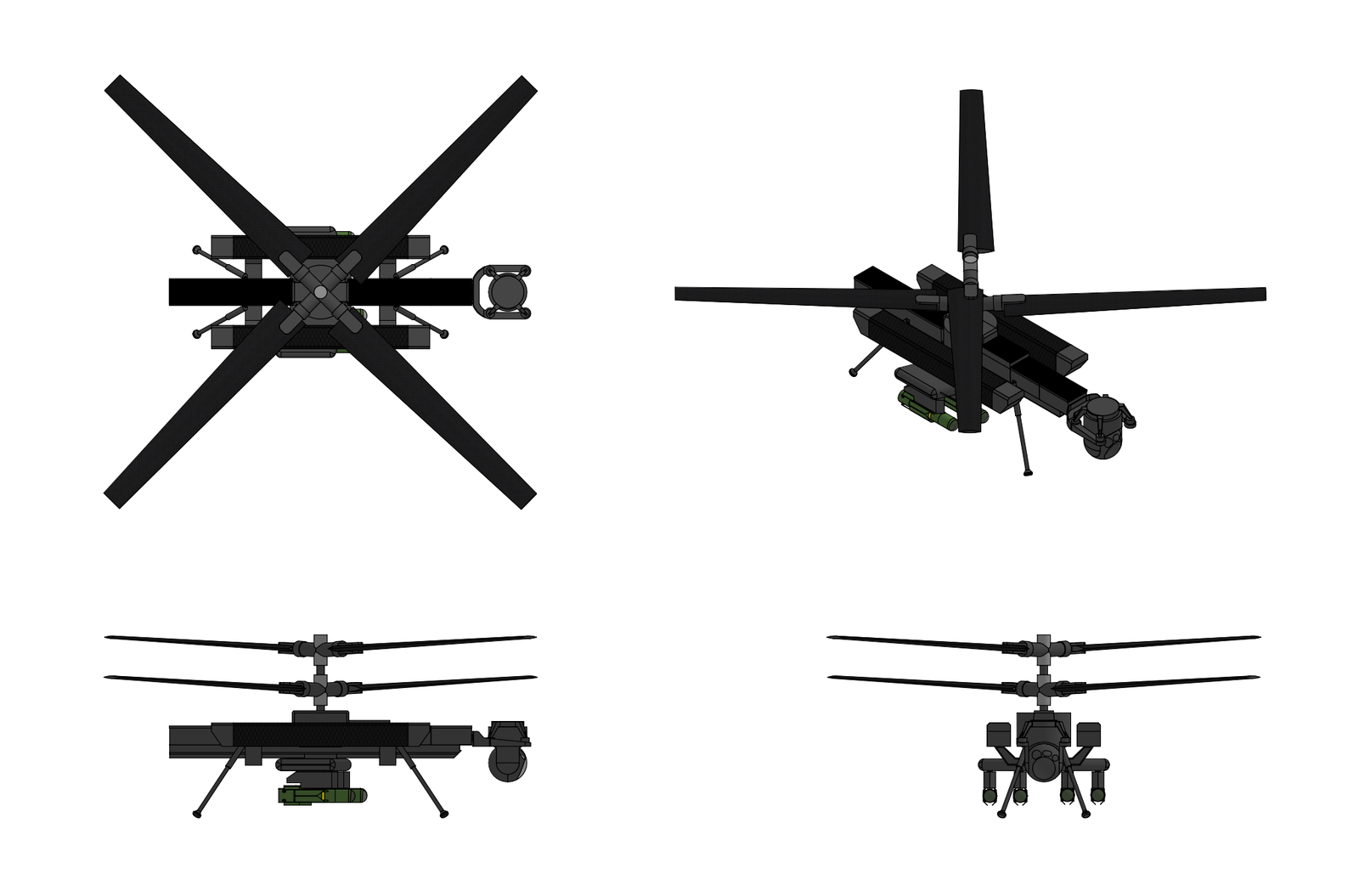

Overview
The SDI T 60 Albatross is an ultra-large strategic seaplane designed by SDI Aerospace Systems. The Albatross is designed to operate in standard flight at altitudes up to 6,000 meters and in ground effect very close to the surface of the ocean, significantly extending its unrefueled range. The capable of taking off and landing in up to Sea State 5, operating in ground effect up to Sea State 6


Design & Construction:
The Albatross features a a high-wing monohull flying boat configuration with wingtip stabilizing floats. The fuselage features a hydrodynamically shaped planing hull with a V-shaped bottom, a longitudinal planing step at the center of buoyancy, spray rails along the hull chines, and a gradually tapering afterbody aft of the step. The hull is designed to transition smoothly from displacement mode at rest and low speed through the "hump" speed regime to planing mode at takeoff speed, with stable hydrodynamic characteristics throughout the speed range and in the specified sea states. The forebody extends from the bow to the main planing step and is the primary hydrodynamic surface during takeoff and landing. The forebody cross-section features a pronounced V-shaped bottom. The deep-V bow section with its high deadrise angle reduces the vertical acceleration from impact loading when the hull strikes wave crests during the planing takeoff run, distributing the hydrodynamic impact over a longer time interval and a wider area. The decreasing deadrise toward the step improves hydrodynamic lift efficiency at planing speed, where the hull must support the aircraft's weight until aerodynamic lift transfers the load to the wings. The forebody chines are fitted with integral spray rails, narrow strakes that deflect spray laterally and downward away from the hull sides, the wing, and away from the engine air intakes and propeller discs. The spray suppression consists of the primary spray rails at the main chine, secondary spray rails at approximately one-third and two-thirds of the beam width, and a bow spray dam forward of the cockpit station. The main planing step is a transverse discontinuity in the hull bottom located at approximately 40% of the waterline lengt, roughly 50 meters aft of the bow, near the center of buoyancy. The step extends across the full beam of the hull bottom, and during takeoff ventilates the afterbody by introducing air beneath the hull aft of the step, breaking the suction that would otherwise develop between the afterbody bottom and the water surface. The step also provides a clean hydrodynamic break preventing the hull from porpoising, a type oscillatory pitching instability, at intermediate speeds. The afterbody extends from the planing step to the stern and tapers gradually upward and inward. The afterbody cross-section has a shallower deadrise ( than the forebody and a narrower beam. During displacement and low speed taxiing the afterbody is immersed and contributes to buoyancy and longitudinal stability. During the planing takeoff run the afterbody is progressively lifted out of the water by the combined force of aerodynamic lift on the wings and hydrodynamic lift on the forebody with the step ventilation preventing afterbody suction. The afterbody terminates in a stern ramp structure that serves as the primary cargo loading and unloading access. In the closed position the stern ramp seals the aft end of the cargo hold and presents a smooth hydrodynamic surface to the water. In the open lowered position, the ramp extends aft and downward to contact a pier, beach, or the surface of a loading dock vessel, permitting roll-on/roll-off loading of vehicles and ISO containers. The stern ramp is sealed by inflatable gaskets and is reinforced to withstand wave impact loads in the closed position.

The aircraft features a high mounted unswept wing with a pronounced anhedralat the outboard sections. This droop wing configuration enhances ground effect efficiency by keeping a large portion of the wing surface close to the surface during low altitude flight and provides structural depth at the wing root to accommodate cargo storage cavities within the inboard wing. The wing passes through the fuselage as a continuous box structure, integrating structurally with the fuselage frames and transferring loads efficiently. The drooped wingtips terminate in integral tip float assemblies that provide transverse (roll) stability when the aircraft is on the water. The tip floats are permanently extended and are shaped to minimize aerodynamic drag during flight while providing the necessary buoyancy reserve during water operations. Each wingtip float is a streamlined watertight body approximately 12 meters in length constructed from graphite/epoxy composite skins over an aluminum alloy internal frame. The floats are integral with the wingtip structure and are not retractable and are aerodynamically faired to minimize drag during flight. Each float provides a buoyancy reserve of approximately 40,000 kilograms when fully immersed, sufficient to prevent the wingtip from submerging even in Sea State 6 beam-sea conditions. In calm water at rest, the wingtip floats normally ride clear of the water surface with the aircraft's transverse stability provided by the hull metacentric height alone. As sea conditions increase wave action causes the aircraft to roll, and the leeward float contacts the water to provide a righting moment that limits the roll angle. In Sea State 6 conditions (significant wave height 4–6 meters), the floats are expected to be intermittently immersed on alternating sides and their structural design accounts for the resulting cyclic hydrodynamic impact loading.

The wing and hull primary structure are constructed from marine grade aluminum alloy (5083-H321 and 5456-H116 for the bottom plating, 6061-T6 for internal frames) with GLARE fiber metal laminate reinforcement at the most highly loaded regions including the forebody bottom forward of the step, the step transition zone, and the stern ramp surround. The GLARE fiber metal laminate consists of alternating layers of thin aluminum alloy sheets and glass fiber/epoxy prepreg layers and is approximately 10% lighter than equivalent monolithic aluminum at the same strength, has superior fatigue crack growth resistance, and has excellent impact and damage tolerance. The hull is designed to the "ultimate factor of safety" approach used in both naval architecture and aerospace structural certification with the design condition being a Sea State 5 water impact at maximum landing weight. The design slamming pressure on the forebody bottom forward of the step reaches approximately 350–500 kPa during a worst-case wave impact, requiring bottom plating thicknesses of 18 to 25 mm depending on frame spacing. Longitudinal and transverse frames provide the internal stiffening with frame spacing of approximately 450 mm in the high-load forebody region. The hull is divided into twelve watertight compartments by transverse bulkheads extending from the keel to above the design waterline. The watertight subdivision is designed to a two compartment damage stability standard, the aircraft is designed to remain afloat and stable with any two adjacent compartments flooded in calm water at maximum displacement. Each watertight compartment is equipped with electric powered bilge pumps (with emergency backup from the aircraft hydraulic system) and bilge level sensors connected to the cockpit marine systems annunciator panel. The bilge system is capable of draining any single compartment at a rate exceeding the maximum calculated flooding rate from a hull breach of up to 0.5 square meters in area. All hull surfaces exposed to seawater are protected by a multilayer corrosion protection system consisting of an anodic oxidation of the aluminum alloy substrate, a chromate free epoxy primer, an intermediate epoxy barrier coat, and an antifouling topcoat on the external wetted surfaces. Sacrificial zinc anodes are installed at regular intervals along the hull bottom and around all through-hull fittings. All dissimilar metal joints are isolated by nonconductive bushings and sealants to prevent galvanic corrosion. The T-tail empennage is constructed from carbon fiber reinforced polymer (CFRP) composites. The vertical stabilizer features a multi-spar torsion box constructed from CFRP skins with co-cured stringers, CFRP spar webs, and aluminum alloy rib structures at the attachment points and at the horizontal stabilizer mounting interface. The horizontal stabilizers are similarly of CFRP composite construction with aluminum alloy root attachment fittings. The rudder and elevators are of CFRP sandwich construction providing low weight with high stiffness. The empennage is mounted well aft and relatively high on the fuselage, positioned above the wing wake in ground-effect operation to ensure adequate control authority in all flight regimes.


Vehicle Management System & Flight Control Surfaces:
The T 60 employs a full-authority, quadruplex-redundant fly-by-wire (FBW) flight control system with no mechanical reversion. The FBW control laws implement three primary operating modes. Normal Law provides full-authority envelope protection including angle-of-attack limiting, load factor limiting, bank angle protection, over-speed protection, and automatic pitch trim. The pilot commands are interpreted as load-factor and roll-rate demands in the pitch and roll axes, with automatic stability augmentation and turn coordination. Direct Law provides proportional surface command in response to stick inputs, with basic stability augmentation but without envelope protection, and is available as a fallback if sufficient air data or inertial reference sources are lost. Degraded Law provides a reduced-authority, gain-scheduled proportional mode available on the remaining channels following multiple system failures. A Water Operations Mode is additionally active during water takeoff, landing, and on-water taxiing in all modes, and provides additional augmentation functions including porpoising suppression, spray avoidance, and crosswind water handling. During the planing phase of takeoff and landing the flight control system uses the elevator to actively damp longitudinal (pitch) oscillations that could develop into porpoising instability. The system uses accelerometer feedback and hull-mounted pressure sensors to detect the onset of porpoising and commands elevator deflections to counteract the oscillation before it develops. For spray avoidance the system modulates the aircraft's pitch attitude during the planing run to maintain the optimal trim angle for spray suppression, nose up enough to prevent the bow from plowing into waves but not so nose up that the afterbody reenters the water aft of the step. On the water the rudder and differential propeller thrust provide directional control. In crosswind conditions during the takeoff run, the system coordinates rudder, differential thrust, and aileron inputs to maintain the desired ground track while compensating for wind induced drift and asymmetric hydrodynamic forces on the hull.

The primary flight controls comprise inboard and outboard ailerons on each wing for roll control, elevators on the T-tail horizontal stabilizers for pitch control, and a rudder on the vertical stabilizer for yaw control. Secondary flight controls include leading edge slats, trailing edge flaps (Fowler-type inboard and plain outboard), ground and flight spoilers on the upper wing surfaces, and a trimmable horizontal stabilizer. The control surfaces of the aircraft are actuated using a a hybrid 2H/2E actuation architecture with conventional hydraulic servo-actuators powered by the aircraft’s two centralized hydraulic systems and electro-hydrostatic actuators (EHAs) driven by the aircraft's two electrical systems. The aircraft has two independent hydraulic systems operating at 350 bar designated GREEN and YELLOW, and are each engine-driven by four engine-driven pumps each (one on each engine pair) and power the conventional hydraulic flight control actuators, landing gear, nose wheel steering, brakes, and cargo ramp. All hydraulic reservoirs are self-sealing and pressurized with nitrogen. The primary electrical system is twin 270 VDC / 115 VAC hybrid electrical networks. Each engine drives a 150 kVA integrated drive generator (IDG), providing a total generation capacity of 600 kVA. The two 270 VDC primary distribution buses supplies the EHA flight control actuators, electric motor-driven hydraulic pumps, environmental control system compressors, and other high-power loads directly, eliminating the weight of transformer-rectifier units. Conversion to 115 VAC 400 Hz and 28 VDC is provided by static inverters and DC-DC converters for legacy and lower-power avionics loads. The 2H/2E architecture provides maximum survivability against both hydraulic system battle damage and electrical system failures, ensuring that at least two fully independent control channels remain available following any single-system catastrophic failure.


Propulsion:
  • Name: SDI TPM900
  • Type: Turboshaft
  • Length: 4,900 mm
  • Diameter: 2,100 mm
  • Dry Weight: 5,900 kg
  • Compressor: 4 stage LPC, 9 stage HPC
  • Combustor: annular combustor
  • Turbine: two stage HPT, two stage LPT, four stage PT
  • Maximum power output: 60,000 kW
  • Overall Pressure ratio: 50:1
  • Specific fuel consumption: 0.205 kg/kW-hr
  • Power-to-weight ratio:: 10.1 kW/kg
The propulsion system consists of four propeller drive units, each integrating two turboshaft engines, a combining transmission, two clutch mechanisms, and one contra-rotating propeller assembly into a single wing mounted nacelle. The total propulsion system thus comprises eight turboshaft engines, four transmissions, eight clutch mechanisms, and four contra-rotating propeller assemblies, together producing a combined maximum shaft horsepower of approximately 640,000 SHP. During takeoff and climb both engines in each drive unit are clutched to the transmission with all eight engines operating at maximum power. This mode provides the full 640,000 SHP necessary to accelerate the aircraft to rotation speed and climb to cruise altitude at maximum gross weight. In cruise mode one engine in each drive unit is unclutched from the transmission and is either shut down or maintained at idle. The remaining four engines (one per propeller) operate at or near their peak efficiency point, dramatically reduces specific fuel consumption compared to operating all eight engines at part power. If one engine fails or is shut down for non-emergency reasons the remaining engine on that propeller drive unit continues to provide propulsion through its clutch and the shared transmission. The remaining three propeller units continue operating normally with two engines each, providing approximately 87.5% of total installed power, more than sufficient for continued safe flight.

The LPC is a four-stage axial-flow compressor operating at an LP spool speed of approximately 5,200 RPM and produces a pressure ratio of approximately 3.0:1. All four LPC rotor stages are integrally bladed rotors (blisks) manufactured from T- 6242 (Ti-6Al-2Sn-4Zr-2Mo) near-alpha titanium alloy. The HPC is a nine stage axial flow compressor with a pressure ratio of approximately 17:1 driven by the high-pressure turbine through a concentric shaft. All nine HPC rotor stages are integrally bladed rotors (blisks) manufactured from titanium aluminide (γ-TiAl) intermetallic alloy. Stages one through four employ Ti-43.5Al-4Nb-1Mo-0.1B γ-TiAl while stages five through nine employ Ti-46Al-5Nb-1W. The TiAl blisks are manufactured by a combination of centrifugal casting for the near-net-shape disc/blade preform and five-axis CNC machining for final airfoil contour and surface finish. The blisks are subsequently hot isostatically pressed (HIPed) to close any residual casting porosity, followed by controlled heat treatment to develop the desired duplex (lamellar + gamma) microstructure that provides an optimum balance of tensile strength, fatigue resistance, and ductility at the high temperatures (up to approximately 800°C) encountered in the HPC. The HPC stator vanes in the first five stages are variable, actuated by a unison ring and lever mechanism driven by a hydraulic actuator under FADEC control. The rear four stages have fixed stator geometry. The combustion section features a single annular combustor with a dual-dome rich-burn/quick-quench/lean-burn architecture incorporating ceramic matrix composite primary structural liner components. The combustor includes twenty fuel nozzles that inject atomized fuel into the primary zone through simplex pressure swirl nozzles with integrated air-blast atomization. The combustor is designed for a turbine inlet temperature of approximately 1,700°C at maximum power. The inner and outer combustor liners are constructed from silicon carbide fiber reinforced silicon carbide matrix (SiC/SiC) ceramic matrix composite manufactured by chemical vapor infiltration (CVI) of a silicon carbide matrix into a preform of continuous silicon carbide fibers, coated with an environmental barrier coating (EBC) of ytterbium disilicate (Yb₂Si₂O₇) rare-earth silicate. The EBC coated CMC panels are attached to a metallic support structure by floating mounting pins that accommodate the differential thermal expansion between the CMC and the metallic casing. The combustor liner is film cooled with approximately 10% of the compressor discharge air dedicated to liner cooling with the remaining 90% participating in the combustion process or diluting the combustor exit gas to the desired turbine inlet temperature profile. The high-pressure turbine (HPT) is a two stage axial flow turbine that extracts energy from the combustor discharge gas to drive the high pressure compressor. The HPT operates with first-stage nozzle guide vanes exposed to gas temperatures of 1,700°C and first-stage rotor blades exposed to temperatures approaching 1,550°C. The HPT blades are sixth-generation nickel-base single crystal (SC) superalloy castings with internal cooling passages and film cooling holes produced by electrical discharge machining (EDM) and shaped-hole laser drilling. Each blade has approximately 150 to 200 film cooling holes that exhaust a layer of cooler compressor bleed air over the blade external surface, maintaining the blade metal temperature below approximately 1,050°C even in the 1,700°C gas stream. The blades are coated with a duplex thermal barrier coating system consisting of a MCrAlY + PtAl bond coat and a gadolinium zirconate (Gd₂Zr₂O₇) ceramic top coat. HPT first and second stage nozzle guide vanes (NGVs) are constructed from SiC/SiC ceramic matrix composite inserted into metallic Inconel 718 alloy shroud platforms that provide the structural attachment to the turbine casing. The outer air seals are SiC/SiC with an abradable EBC coating on the inner surface that permits the blade tips to rub during transient conditions without damaging the blades themselves. The LPT is a two stage axial-flow turbine that extracts energy to drive the four stage LPC through the LP spool shaft. The LPT blades are constructed from the same sixth-generation nickel-base single crystal (SC) superalloy as the HPT blades but are not cooled. LPT nozzle guide vanes are SiC/SiC with EBC coating and are also not cooled. The free power turbine (FPT) is a four stage axial flow turbine that extracts the remaining usable energy from the gas exiting the high pressure turbine and converts it to shaft power for driving the propeller transmission. The four stage FPT is designed to expand the HPT exhaust gas from an inlet temperature of approximately 850–950°C and a pressure of approximately 3.5:1 above ambient to near-atmospheric conditions at the exhaust. All power turbine stages employ uncooled Ti-43.5Al-4Nb-1Mo-0.1B γ-TiAl alloy blisks and vanes. The FPT casing is a two piece split construction with abradable aluminum-silicon/polyester rub strips on the inner surface to maintain tight blade tip clearances for aerodynamic efficiency while preventing blade tip rubs that could cause fatigue cracking. The FPT rotor drives the output shaft which transmits the full 60,000 kW to the transmission input. The output shaft is a hollow high-strength steel forging operating at approximately 5,800 RPM at the maximum continuous power condition. The shaft is supported by two main bearings, a duplex angular contact ball bearing at the forward end that locates the rotor axially and carries combined thrust and radial loads and a cylindrical roller bearing at the aft end that accommodates thermal expansion of the rotor while carrying radial loads only. Both bearings are housed in squeeze-film damper assemblies to attenuate rotor dynamic vibration. The output shaft exits the engine through an aft facing power takeoff flange that connects to the clutch input. The shaft-to-clutch interface is a splined coupling with a torque capacity of 150% of maximum engine torque, providing margin for transient torque spikes during clutch engagement and disengagement.

Each of the four propeller drive units incorporates a single combining transmission that receives power from two TPM900 engines via two independent clutch mechanisms and delivers a single combined output to the contra-rotating propeller assembly. The transmission employs an epicyclic planetary gear arrangement in a compound configuration that combines the two engine inputs into a single output; provides the necessary speed reduction from the engine output shaft speed (5,800 RPM) to the propeller speed (140 to 180 RPM), and it splits the single combined output into two contra-rotating outputs for driving the forward and aft propeller rotors. The two engine inputs enter the transmission through parallel input shafts each rated for the full single engine torque of approximately 50,000 N·m at 5,800 RPM. Each input shaft drives an input bevel gear that meshes with a common combining bevel gear on the primary power shaft. This bevel gear arrangement combines the two engine inputs onto a single shaft while permitting each input to rotate independently when its associated clutch is disengaged. The bevel gears are spiral-bevel type with a 1:1 ratio manufactured from case carburized and ground 14NiCrMo13-4 steel. The primary power shaft drives the main reduction gearset which is a compound two stage epicyclic planetary unit. The first stage is a simple planetary set with the input to the sun gear, the planet carrier as the output, and the ring gear held stationary. This stage provides a speed reduction of approximately 5.5:1. The second stage is a star epicyclic arrangement (planet carrier fixed, ring gear as output) that provides an additional reduction of approximately 6.2:1 for a total reduction of approximately 34:1 from the input shaft to the main output. The planetary gears in both stages are spur gears. selected to avoid the axial thrust loads that helical gears would impose on the bearing system. Each stage incorporates five planet gears to distribute the transmitted torque among multiple gear meshes, reducing the load per mesh and improving reliability. The planet pins are supported in double-row spherical roller bearings that accommodate misalignment and distribute the pin bending loads. All gear teeth are case carburized 14NiCrMo13-4 steel. The output of the second planetary stage drives a differential gear arrangement that splits the power into two contra-rotating output shafts for the forward and aft propeller rotors. This differential is a bevel-gear set arranged such that the input bevel gear drives two opposing output bevel gears that rotate in opposite directions at equal speed. The differential housing is free to rotate on bearings concentric with the propeller axis, and reaction torque is taken through the transmission case to the nacelle structure. The two contra rotating output shafts are concentric, the forward rotor shaft is a hollow outer shaft and the aft rotor shaft passes through the center of the forward shaft on its own bearing system. Both shafts exit the forward face of the transmission housing through labyrinth seals and connect to the propeller hub assembly via high strength splined couplings. The concentricity of the shafts is maintained by four sets of inter-shaft angular contact ball type bearings that support the inner shaft within the outer shaft and permit independent rotation. The transmission lubrication system is an independent, self-contained system separate from the engine oil systems. It uses the same synthetic oil as the engines but maintains a dedicated oil tank, pump system, filtration circuit, and cooling loop. The system delivers approximately 600 liters per minute of filtered oil to the gear meshes and bearings through precision-aimed spray jets. The oil collects in the sump at the bottom of the transmission housing and is scavenged by four scavenge pumps (one per quadrant of the housing) back to the oil tank. Heat rejection from the transmission at maximum continuous power is approximately 750 kW. This heat is removed by an oil-to-air cooler integrated into the nacelle, supplemented by an oil-to-fuel heat exchanger. The oil temperature is maintained between 80°C and 120°C under all operating conditions. Chip detectors, oil temperature sensors, oil pressure sensors, and vibration accelerometers are installed throughout the transmission and are monitored continuously by the FADEC for health and usage monitoring purposes. Each drive unit incorporates two identical clutch mechanisms, one per engine, positioned between the engine output shaft and the transmission input shaft. Each clutch is a multiplate dry friction type incorporating a stack of alternating drive plates splined to the engine output shaft coupling) and driven plates splined to the transmission input shaft. The friction surfaces are sintered metallic friction material (copper-iron matrix with molybdenum disulfide and graphite solid lubricants) bonded to a steel backing plate. The clutch is normally disengaged and is engaged by hydraulic pressure acting on a piston that compresses the disc stack through a diaphragm spring mechanism. This ensures that in the event of hydraulic system failure the clutch releases automatically, preventing a seized or failed engine from backdriving the transmission or propeller. The engagement hydraulic pressure is approximately 35 bar, supplied by the transmission lubrication system through a FADEC controlled proportional servo valve. The proportional valve permits the FADEC to modulate the engagement pressure during the clutch engagement sequence, enabling smooth, controlled load transfer from zero to full torque over a programmable ramp time.

Each of the four propeller drive units is fitted with a contra-rotating propeller (CRP) assembly 15 meters in diameter with two coaxial rotors each carrying eight blades. The propeller assembly consists of the forward rotor hub with eight blades and its associated pitch change mechanism and the aft rotor hub with eight blades and its own independent pitch change mechanism. The two rotors are spaced approximately 1.5 meters apart axially to reduce aerodynamic and acoustic interaction. Each propeller blade has a span of approximately 6.5 meters from root to tip. The blade planform features a broad chord at the root that tapers to a narrow tip with moderate sweep introduced in the outer 30% of the span. The swept tip delays the onset of compressibility effects at the blade tip, where the local Mach number reaches approximately 0.70 at maximum rotational speed. The blade twist distribution varies approximately 45 degrees from root to tip with a coarse pitch angle at the root and a fine angle at the tip. This twist distribution is optimized for the cruise condition of approximately 240 knots (ground-effect altitude, 140 RPM) with acceptable off-design performance at the takeoff condition (approximately 100 knots, sea level, 180 RPM). The airfoil crosssection transition from a thick, high-lift root airfoil (approximately 18% thickness-to-chord ratio) to a thin, high-efficiency tip airfoil (approximately 8% t/c) designed for low drag at transonic Mach numbers. The blades are constructed from carbon fiber reinforced polymer composite s over a structural closed-cell foam core with a Ti-6Al-4V titanium alloy leading edge erosion sheath extending from approximately 5% chord on the suction side around the leading edge to approximately 15% chord on the pressure side. The CFRP layup comprises unidirectional carbon fiber plies oriented along the blade span for bending stiffness, ±45° cross-plies for torsional stiffness, and woven cloth surface plies for impact damage tolerance. The blade root section transitions from the airfoil shape to a cylindrical shank that is retained in the hub by a large diameter, multi row roller bearing permitting blade pitch rotation. The shank is a monolithic titanium alloy forging integrally bonded to the CFRP spar structure during blade manufacture. The outer surface of each blade is coated with a polyurethane rain and salt-spray erosion protection layer.

Each propeller rotor hub is a single piece Ti-6Al-4V titanium alloy forging with eight radially extending arms each of which incorporates a blade retention bore and a pitch change bearing housing. The hub is connected to its respective transmission output shaft via a bolted flange coupling with a curvic type self-centering face spline. Each blade is individually controlled in pitch by a dedicated hydraulic pitch change actuator housed within the hub arm. The actuator is a double acting hydraulic cylinder that acts on the blade retention bearing through a crank mechanism, converting the linear actuator stroke into rotary blade pitch motion. The pitch range extends from full fine pitch through the normal operating range to full feather. A reverse pitch capability is provided to approximately −15° for water braking during landing run deceleration. Hydraulic pressure for the pitch change actuators is supplied from the transmission lubrication system through a transfer bearing at the hub center. The transfer bearing delivers pressurized oil from the stationary transmission housing to the rotating hub through a multi-channel seal assembly, with separate channels for fine-pitch, coarse-pitch, and feather/unfeather commands. Rather than the conventional approach of commanding all blades on a rotor to the same pitch angle simultaneously through a swashplate or spider mechanism each blade has its own independent pitch actuator controlled by its own FADEC commanded servo valve. By modulating the pitch of individual blades as a function of azimuth position the system can counteract the periodic aerodynamic loads that create vibration at the blade-passing frequency. This reduces the vibratory loads transmitted to the nacelle and airframe, improving structural fatigue life and crew comfort. During crosswind flight, sideslip, or yawed ground effect operations the propeller encounters non-uniform inflow that causes periodic load variations as each blade rotates through the disc. IBC modulates the blade pitch as a function of azimuth to equalize the load across the disc, reducing the net asymmetric force and moment on the propeller shaft and thereby reducing the cyclic loads on the transmission and nacelle mountings. By detuning the blade-passing frequencies of the forward and aft rotors through small per-blade pitch offsets, the acoustic interaction between the two rotor wakes can be modulated to reduce the tonal noise components that are the primary sources of community and cabin noise. The primary feathering method is the normal hydraulic pitch change system, commanded by the FADEC to slew the blades to the feather angle. Backup feathering is provided by a mechanical spring accumulator in each hub arm consisting of a stack of Belleville disc springs stores sufficient energy to drive the blade to the feather position against aerodynamic and friction forces if hydraulic pressure is lost. The spring accumulator is continuously charged by the normal hydraulic pressure and releases automatically when pressure drops below a preset threshold. A tertiary feathering mechanism uses a centrifugal latch weight on each blade that releases a counterweight mechanism at overspeed, driving the blade toward feather by centrifugal twisting moment. Each propeller blade is also equipped with an electrothermal deicing system comprising bonded resistive heater mats laminated beneath the polyurethane erosion protection layer on the outboard 60% of the blade leading edge. The heater mats are powered by slip-ring assemblies in the hub and are energized in a cyclic sequence to limit the peak electrical power demand to approximately 120 kW per propeller assembly. The deicing system is commanded by the FADEC based on inputs from an ice detection sensor mounted on the nacelle and from outside air temperature measurement.

The TPM900 includes a dual-channel full authority digital electronic control system (FADEC). The FADEC hardware comprises sixteen Electronic Engine Controllers (EECs) organized as eight dual-channel units, one dual-channel EEC per engine. Each EEC contains two independent processing lanes each of which is a complete, self contained computing system capable of fully controlling the associated engine and its share of the drive unit functions. Only one channel is active at any time while the other is in hot standby with automatic switchover occurring if the active channel detects a fault through its built-in self-test (BIST) routines. The eight EECs communicate with each other and with the aircraft flight control computers, cockpit displays, and maintenance data system through a dual-redundant AFDX Ethernet data network. This high-speed deterministic network permits the EECs to share engine and propeller state data in real time, enabling the cross drive unit coordination functions (power matching, asymmetric thrust management, and overall power scheduling) for managing four drive units as an integrated propulsion system rather than four independent installations. Each EEC also maintains a dedicated, hardwired analog/discrete connection to its own engine sensors and actuators, independent of the AFDX network. These hardwired connections ensure that each EEC can continue to control its engine even in the event of complete loss of the data network. In this degraded mode, the EEC operates the engine in a "single engine standalone" mode using only local sensor data, without cross-drive-unit coordination. Control modes include independent control of blade pitch and propellor speed allowing variable synchrophasing control of each propfan engine to minimize engine noise and vibration, protective measures for regulating turbine-inlet temperature and preventing inadvertent engine overspeed or overtorque, and fault modes allowing for propellor blade feathering and gas generator compressor/turbine section windmilling if an engine fails or has to be shut down in flight. The FADEC control system is housed in a dual-channel electronic control unit containing circuitry connected to various engine sensors whose inputs are used by the FADEC system to control fuel flow, propeller pitch, variable compressor vanes and stators, bleed air flow, and other systems to optimize the performance of the engine throughout the flight envelope.

The Albatross features a dedicated waterborne maneuvering thruster system that provides the aircraft with self-powered, omnidirectional movement on the water surface independent of the main propulsion engines, used for precise pierside positioning during cargo operations, for maneuvering in confined waterways or harbor approaches, and for maintaining station or adjusting heading while at anchor or on a sea anchor in high sea states. The waterborne maneuvering propulsion system includes six electrically driven tunnel thrusters installed in three pairs along the hull. Two bow thrusters are Installed in transverse tunnels through the hull approximately 12 meters aft of the bow, forward of the planing step. Each bow thruster is a fixed pitch propeller of approximately 1.5 meters diameter driven by a 750 kW (permanent-magnet synchronous electric motor. . The bow thrusters produce a maximum lateral thrust of approximately 50kN each.T wo stern thrusters are Installed in transverse tunnels through the hull approximately 8 meters forward of the stern ramp, aft of the planing step in the afterbody. Each stern thruster is identical to the bow thrusters (1.5 m diameter, 750 kW motor, 45 50 thrust). The stern thrusters provide lateral force at the aft end of the hull for controlling the aircraft’s heading and for crabbing laterally to align with a pier or dock. Two midship thrusters are Installed in transverse tunnels through the hull at approximately the longitudinal center of the aircraft, Each midship thruster is a larger unit with a 2.0-meter iameter propeller driven by a 1,200 kW motor producing a maximum lateral thrust of approximately 75 kN. The midship thrusters provide lateral translation force for pure sideways movement (crabbing) of the entire aircraft, supplementing the bow and stern thrusters. Each thruster tunnel is a cylindrical tunnel passing through the hull with its thrust axis perpendicular to the aircraft centerline. The tunnels are fabricated from welded marine-grade aluminum alloy with reinforcing rings at the hull penetration points to maintain watertight integrity and distribute the thruster reaction forces into the hull structure. The tunnel entrances on each side of the hull are fitted with hydraulically actuated sliding doors that close flush with the hull external surface when the thrusters are not in use. The closed doors restore the smooth hull lines for minimum hydrodynamic drag during takeoff, landing, and high speed taxiing. The thruster tunnels are positioned above the design waterline draft at maximum takeoff weight when the aircraft is at planing speed, ensuring they do not interfere with the hydrodynamic flow over the hull bottom during the takeoff run. At displacement rest, the tunnels are submerged below the waterline at the correct depth for effective lateral thrust generation. The maneuvering thrusters are controlled from the cockpit via a joystick controller mounted on the center pedestal between the two pilot seats. The joystick provides lateral deflection commands lateral translation, rotation commands heading change, and forward/aft deflection commands low-speed longitudinal thrust (supplementing or replacing main propeller thrust during close maneuvering). An autopilot mode is available for automatic station keeping and automatic docking approach. freeing the pilots from continuous manual thruster control during cargo loading and unloading operations.


Avionics:
FMG 240 Radar: The ]FMG 240 is a comprehensive, X-band airborne radar system designed for weather detection and tactical navigation which provides weather detection along with air-to-air detection and high-resolution ground mapping (HRGM) doppler beam sharpening precision ground mapping (PGM) syntenic aperture radar (SAR) modes. The FMG 240 radar uses a solid state transmitter mounted on a 2-axis gimbal in the nose of the aircraft with a maximum transmit power of 917 watts. Weather detection modes includes predictive wind shear (PWS), turbulence detection out to 110 kilometers, predictive lightning, predictive hail, and ​rain echo attenuation compensation technique (REACT) with the ability to automatically detect and avoid weather at ranges up to 600 kilometers from the aircraft. The FMG 24- also supports ground mapping capability with the ability to image terrain at ranges up to 150 kilometers from the aircraft with doppler beam sharpening providing X2 and X4 zoom modes for producing detailed imagery of terrain and geographical features.

RLG 640 Missile Approach Warning System: The RLG 640 is a passive missile warning system installed in the aircraft which provides warning of incoming threat missiles. The RLG 640 system employs four optical sensor heads with integral optical signal converters mounted around the aircraft which provide combined 360 degree azimuth coverage, a central processor which inputs and analyses signals from the four sensor heads to detect and classify threats, and a central control unit located in the cockpit which provides visual and aural threat warning to the crew and allows for control of the system. Each RLG 640 sensor heads contains an ultra-violet (UV) single-pixel quadrant sensors with an adjunct UV sensor for improved dynamic blanking, a laser warning sensor which warns the crew when the aircraft is being illuminated by a laser designator/illuminator/rangefinder or if the aircraft is being targeted by a laser beam-riding missile, and a short-wave infrared (SWIR) camera which provide detection and tracking of incoming rocket and tracer ammunition. An interface with the aircraft's FMB 790 radar warning system allows the RLG 640 system to distinguish between radar and infrared guided missile threats and to automatically queue the countermeasures system to dispense flares when the system identifies an oncoming IR guided missile.

FMB 790 Radar Warning Receiver System: The FMB 790 Radar Warning Receiver is a digital radar warning system which alerts the crew the aircraft is being illuminated by a threat radar. The FMB 790 provides 360 detection of radar signals in the 0.5-40 MHz range and employs two 2-20 Mhz and two 2-40 MHz spiral antenna and a 0.5- 2 MHz blade antenna which feed into four wideband superheterodyne digital quadrant receivers connected to a electronic warfare processor. The FMB 790 system continuously detects and intercept RF signals including both continuous wave and pulse-doppler around the aircraft and displays threat signals to crew on a cockpit display unit along with warning tones which warn the crew when the system detects the aircraft is being illuminated by a hostile radar. Data from the FMB 790 system is automatically transmitted to the aircraft's TKW 680 countermeasures dispenser system which can be set to automatically disperse chaff and expendable active radar decoys when the FMB 790 system detects the aircraft is being targeted by radar guided missiles.

TKW 680 Countermeasures Dispenser System: The TKW 680 is an airborne countermeasures dispenser system designed to dispense chaff, flares, and other expendable decoys to increase aircraft survivability. The TKW 680 system consists of multiple tail mounted cartridge dispenser modules (CDMs) each capable of containing up to 32 5.0 cm x 2.5 cm x 8.0 cm countermeasures each and a central defensive aids controller (DAC) unit with inputs from both the missile/laser warning system and RWR system. When a threat missile is detected by the aircraft's missile/laser warning system or RWR systems the defensive aids controller of the TKW 680 automatically selects appropriate expendable countermeasures to be released by the system's dispensers to decoy or spoof away the incoming missile. Countermeasures supported including pyrophoric spectral flares for decoying IR missiles and chaff, and active digital radio frequency memory (DRFM) decoys for decoying RF guided missiles.

Advanced Infrared Countermeasure (AIRCM) System: The The Advanced Infrared Countermeasure (AIRCM) system is a directional infrared countermeasure system which employs tunable multi-band quantum cascade laser (QCL) laser dazzlers to counter infrared man portable air defense system (IR MANPADS) threats. The AIRCM system consists of missile warning system interface, central control unit processor, and three laser pointer/tracker units, two on either side of the forward fuselage and one under the tail, which provide combined 360 degree coverage around the aircraft. The missile warning system interface uses the UV and IR sensors of the RWG 64 system to detect and incoming missiles and cue the laser pointer/tracker to track and then jam the incoming missile. Each laser pointer/tracker weighs 16 kilograms and consists of quantum cascade laser (QCL) based optical emitter assembly and a beam steering assembly consisting of a clear hemispherical housing 14 centimeters in diameter containing a laser mirror mounted on a servomotor actuated 2-axis gimbal with a strap-down inertial sensor which provides 360° continuous azimuth and -10°/+ 90°degree elevation coverage with a maximum slew rate of 1200°/s. The gimbal has a maximum slew time of less than 300 milliseconds and can track targets up to 30°/s with less than 0.3 milliradians pointing accuracy. The quantum cascade laser (QCL) used in the AIRCM system employs a GaInAs/AlInAs (gallium-indium arsenide/aluminium indium arsenide) lattice on an InP (indium phosphide) substrate which provides high continuous-wave power output at room temperature and which covers both the mid and long-wave infrared bands used by typical infrared missile seekers (3-12 μm) allowing simultaneous break-lock jamming of infrared guided missiles in multiple infrared spectrum bands. The entire AIRCM system consumes less than 850 watts of peak power and is relatively light and compact with a total weight of less than 56 kilograms including three laser pointer/tracker assemblies and central processor unit.


Cockpit:
The Albatross features a pressurized, fully glass cockpit with pilot, co-pilot and two observer positions. The cockpit includes two night-vision-goggle compatible 40 x 30 degree FOV 1,280 x 1,024 pixel super XGA resolution heads up displays for both the pilot and co-pilot and five 38 centimeter diagonal 1920×1080 Full HD resolution multi-function AMLCD (Active Matrix Liquid Crystal Display) capacitive touchscreen displays with DVI and HDMI inputs with two displays for each pilot and a central console mounted display shared by both pilots. The heads up displays include enhanced vision system (EVS) display capability. The EVS sensor suite comprises a cooled mid-wave infrared (MWIR) camera operating in the 3 to 5 µ mband, a short-wave infrared (SWIR) camera operating in the 0.9 to 1.7 µm band, and a high-definition low-light-level television (LLLTV) camera. Imagery from these sensors is fused algorithmically and displayed on the HUD as a synthetic image that approximates visual conditions, enabling the crew to detect terrain, obstacles, and traffic in instrument meteorological conditions (IMC) at night, and in degraded visual environments (DVE) such as dust, smoke, or fog. Each pilot station also includes a 20 x 13 centimeter 1024 x 768 pixel XGA touchscreen electronic flight bags (EFB). An SDI Digital Map Module (DMM) with 512 GB of removable memory is included in the cockpit which features dual channel digital map capability and supports DTED (Digital Terrain Elevation Data) level 2 (~30 m resolution) and controlled image base 10 meter (CIB-10) resolution satellite imagery maps which support color moving map display capability on the cockpit's multi-function AMLCD displays. The console has four throttles with each pilot having a control stick which is connected to the aircraft's quadruple-redundant electronic flight control system. The Albatross cockpit includes an on-board oxygen generation system (OBOGS) to generate oxygen for the pilots during flight which removes the need to store liquid oxygen bottles in the cockpit. The OBOGS works by taking filtered engine bleed-air and passing it through a pressure-reducing valve to reduce the air to ambient pressure where the air is then passed over a zeolite-filled bed that absorbs the nitrogen molecules in the air which are purged from the bed and vented overboard. Behind the cockpit is a rest area which includes two bunks, two seats, a galley, and a lavatory.


Cargo Compartment:
The Albatross features four cargo compartments including upper and lower fuselage bays and two wing bays. The main fuselage cargo bay is a rectangular volume 61.0 meters long and 15.2 meters wide subdivided horizontally by a into two decks including the lower main cargo deck and the upper main cargo deck. Two wing cargo bays extend laterally from the upper deck level into the inboard wing sections on each side of the fuselage connected through full width openings at the wing/fuselage intersection to the upper main cargo deck, allowing cargo to be moved laterally from the upper fuselage deck into the wing bays via the automated conveyor system. The lower main cargo deck is the primary heavy lift payload compartment of the aircraft. With a width of 15.6 meters and a clear internal height of 5.6 meters it is dimensioned to accommodate two rows of five standard ISO containers placed side by side stacked vertically one on top of the other (5x2 cross section) . The lower deck is directly connected to the stern ramp which opens to the full width and height of the lower deck. This connection makes the lower deck the exclusive loading path for main battle tanks (MBTs), heavy armored fighting vehicles (AFVs), and oversized cargo items that cannot be loaded by the overhead railcar system. Vehicles drive directly up the stern ramp and along the lower deck floor under their own power or via winch, with tie-down fittings embedded in the deck floor at 500 mm intervals in a grid pattern. The lower deck floor is the most heavily loaded structural element in the cargo system and is constructed from marine-grade aluminum alloy plate on longitudinal and transverse aluminum beam frames with local GLARE fiber-metal-laminate reinforcement beneath the pylon positions and the main vehicle traffic lanes. The floor is designed to withstand a distributed load of up to 25,000 kg/m² in the pylon zones (reflecting the concentrated corner fitting loads of double stacked ISO containers) and a rolling point load of 15,000 kg per wheel track, accommodating the ground pressure of fully loaded main battle tank. The upper main cargo deck sits atop the inter-deck floor at a height of approximately 6.0 meters above the lower deck floor. With a clear height of approximately 3.4 meters it accommodates a single layer of standard height ISO containers (2.59 m tall) with approximately 0.8 meters of overhead clearance for the ceiling restraint system. The upper deck accepts five containers side by side in the same 15.2-meter width as the lower deck, yielding a 5×1 cross-section. The upper deck connects laterally through full width openings to the two wing cargo bays on each side and connects forward through a passageway and pressure bulkhead to the cockpit module. The upper deck floor structure serves simultaneously as the ceiling of the lower deck and incorporates the mounting points for the lower deck’s ceiling locating pins. It is constructed from aluminum alloy with GLARE reinforcement panels, designed for a distributed load capacity of 12,500 kg/m² (single layer containers with cargo). The two wing cargo bays are located within the inboard wing structure, one on each side of the fuselage, at the same floor level as the upper fuselage deck. Each wing bay connects to the upper fuselage deck through a full width opening at the wing/fuselage junction and is approximately 26 meters deep and can accommodate 20 (20 foot) or 10 (40 foot) ISO containers parallel to the fuselage in one or two rows of ten abreast. The wing bay cargo placement distributes payload mass along the wing span, substantially reducing wing root bending moments compared to concentrating all payload in the fuselage. Total cargo floor area is approximately 2,800 m² with a 190 TEU capacity (100 lower deck + 50 upper deck + 20 left wing + 20 right wing). The automated cargo load handling system transports ISO containers between the stern ramp/loading dock interface and their stowed positions within the four cargo compartments. The system includes a rrail-and-railcar conveyor system for horizontal transport of containers, a floor mounted pylon system for vertical elevation and restraint of containers, and a ceiling mounted locating pin system for upper restraint of stacked containers. Longitudinal parallel steel rails are installed in the floor of each cargo deck and wing bay. The lower fuselage deck has ten rails (two per container lane, five lanes), the upper fuselage deck has another ten rails, and each wing bay has four rails. The rails extend from the aft end of each deck through the cargo bay to the forward end, and for the upper deck rails continue laterally through the wing/fuselage openings into the wing bays. The railcars are low profile wheeled platforms that ride on the rails and carry the ISO containers horizontally between the tern ramp loading point and the stowed position within the bay. Each railcar is approximately the same width as a container lane (approximately 3.0 meters) and can be various lengths to accommodate different container sizes. A single railcar can carry one 40-foot container, two 20-foot containers, or four 20-foot containers depending on the railcar variant. The railcars roll on small-diameter steel wheels constrained laterally by the rail cross-section with the pitch and yaw of each railcar controlled by the longitudinal spacing of the wheel sets. Railcar propulsion is provided by an external cable-drive winch system similar in concept to a cable-car street trolley. Drive cables extend from winch motors at the forward and aft ends of each deck with the forward most railcar in each row attached to the cable via a bowsprit. When the winch is driven it pulls the leading railcar and all railcars coupled behind it in the same row along the rails. Each row of railcars operates independently, permitting parallel loading of multiple rows simultaneously.

Cargo is loaded through a large hydraulically actuated stern ramp at the aft end of the fuselage. The stern ramp is a large, hydraulically actuated door/ramp that forms the aft wall of the lower cargo deck when closed. The ramp is approximately 15.2 meters wide and approximately 6.0 meters tall. When lowered the ramp extends approximately 12 meters aft of the fuselage stern to provide a gentle gradient for vehicle and railcar access. The ramp is constructed from marine grade aluminum alloy plate with longitudinal and transverse stiffeners, designed for a rolling load of 85,000 kg. The ramp surface is fitted with nonskid coating and flush mounted tie down fittings. The ramp is sealed against water ingress when closed by dual inflatable EPDM rubber gaskets around the entire perimeter with the gaskets inflated by the aircraft pneumatic system to a pressure of 2 bar above ambient hydrostatic pressure. The ramp is raised and lowered by four hydraulic actuators (two per side) powered by the aircraft’s two hydraulic systems. In the event of dual hydraulic system failure, a pneumatic emergency close system can seal the ramp using stored nitrogen pressure, ensuring watertight integrity is maintained. The ramp is fitted with fender systems and self-aligning engagement mechanisms to accommodate the relative motion between the aircraft and the loading vessel in sea conditions up to Sea State 4. In Sea State 5–6, cargo operations are conducted only when the aircraft is beached or moored to a fixed pier structure.
Last edited by The Technocratic Syndicalists on Thu Aug 06, 2026 8:45 pm, edited 5 times in total.
SDI AG
Arcaenian Military Factbook
Task Force Atlas
International Freedom Coalition


OOC: Call me Techno for Short
IC: The Kingdom of Arcaenia

User avatar
The Technocratic Syndicalists
Minister
 
Posts: 2346
Founded: May 27, 2015
Inoffensive Centrist Democracy

Postby The Technocratic Syndicalists » Sat Aug 08, 2026 7:59 pm

Image

T 40 Neptune

General Characteristics:
  • Role: Seaplane
  • Crew: 3 (pilot, copilot, loadmaster)
  • Capacity: 40,000 kg of of cargo
  • Cargo hold: 24.0 m long x 3.1 m wide x 2.4 m tall
  • Length: 60.2 m
  • Wingspan: 43.4 m
  • Height: 13.4 m
  • Wing area: 4,600 m2
  • Empty weight: 62,000 kg
  • Fuel weight: 48,000 kg
  • Max takeoff weight: 140,000 kg
  • Powerplant: 6x SDI TPM780 Turboprop engines, 4,500 kW each
  • Propellers: 6x 6-bladed composite constant speed fully feathering reversible pitch propellers
Performance:
  • Maximum speed: 300 kn (560 km/h)
  • Cruise speed: 280 kn (520 km/h) at 6,000 meters
  • Range:
      4,800 km with 40,000 kg payload
      7,600 km with 30,000 kg payload
  • Ferry range: 13,500 km
  • Service ceiling: 10,000 m
  • Wing loading: [i365 kg/m2[/i]
  • Power/mass: 0.27 kW/kg
  • Takeoff distance: 3,600 m with max payload
  • Landing distance: 3,000 m with max payload
Avionics:
  • SDI FMG 163 Weather Radar
  • SDI RLG 640 Missile Approach Warning System
  • SDI FMB 790 Radar Warning Receiver System
  • SDI TKW 680 Countermeasures Dispenser System
  • SDI Advanced Infrared Countermeasure (AIRCM) System


Overview
The SDI T 40 Neptune is a large multipurpose flying boat designed by SDI Aerospace Systems. The T 40 Neptune is designed around a modular mission architecture supporting a wide spectrum of roles including long-range maritime patrol and anti-submarine warfare, tactical airlift over oceanic routes lacking runway infrastructure, open ocean search and rescue, and aerial firefighting.


Design & Construction:
The T 40 Neptune is a high wing monoplane flying boat with a high mounted wing, a conventional tailed configuration with a single vertical stabilizer and a low mounted horizontal tailplane. Six turboprop engines are mounted in nacelles on the wing leading edge. Hydrodynamic features include flared chine sections, a retractable step dam, twin spray suppression strakes, and a replaceable stainless steel sacrificial keel strip. The fuselage is a slender high length-to-beam ratio hull planing hull with a hydrodynamic design optimized for amphibious operations in sea states up to Sea State 4. Lateral stability on the water is provided retractable outrigger wing floats. Retractable tricycle landing gear is housed in watertight fairings. The hull employs a single transverse step located at approximately 55% of the waterline length. The forebody features a deep V cross section with a deadrise angle of 25° at the step transitioning to 35° at the bow, the aggressive deadrise reducing hydrodynamic impact loads. The forebody chines are sharply defined with spray rails that direct water outboard protecting engine inlets and propellers from spray ingestion. The afterbody aft of the step tapers upward at approximately 7.5° relative to the keel line and terminates in a broad, flat tail extension that provides longitudinal damping on the water and serves as the structural foundation for the rear cargo ramp and clamshell doors. The hull primary structure is a semi-monocoque design employing longitudinal stringers, ring frames, and stressed skin. The lower hull planing surfaces forward and aft of the step use machined AA2060 T8E30 aluminum-lithium alloy plates designed to sustain repeated hydrodynamic impact loads over a 30,000 flight hour design life. The upper fuselage skins are GLARE 5 fiber metal laminate panels. The hull is divided into ten watertight compartments by nine transverse bulkheads with two compartment damage tolerance. The hull is divided into twelve watertight compartments by eleven transverse bulkheads with two compartment damage tolerance. The hull is divided horizontally by a continuous structural interdeck floor into an upper and lower compartments. The interdeck floor is located approximately 2.40 meters above the keel line positioning it above the design waterline at all normal displacement conditions. The interdeck floor provides an additional watertight barrier, even if the lower hull is breached the pressurized upper deck remains dry and structurally intact. The upper deck is pressurized from the cockpit pressure bulkhead to the rear pressure bulkhead with a pressurized length of approximately 28.5 meters. The design cabin altitude is 2,400 m at the maximum operating cruise altitude of 10,000 m. The environmental control system provides conditioned air through a twin pack bootstrap air cycle machine system drawing bleed air from the engine compressor stages. The hull is fitted with a retractable tricycle landing gear system. The nose gear is a twin wheel unit with steerable oleo-pneumatic shock strut retracting forward into a watertight hull bay while the main gear consists of two four-wheel bogie units retracting laterally inward into watertight bays in the lower hull sides. All gear bay doors are hydraulically actuated and mechanically locked with inflatable silicone rubber seals when closed. The main gear shock struts are designed for a sink rate of 3.0 m/s at maximum landing weight. On conventional runways the minimum takeoff distance at MTOW is approximately 2,200 meters while landing distance at MLW approximately 1,600 meters.

The wing is a high mounted cantilever design with a high aspect ratio of 11.3 and taper ratio of 0.375. The airfoil sections use natural laminar flow profiles with a root thickness-to-chord ratio of 18% reducing to 14% at the tip. High lift devices consist of full span leading edge slats and triple slotted Fowler flaps extending from the inboard nacelle to the outboard sponson station. The trailing edge flaps deploy to a maximum of 55° for water approach and landing. The BLC system directs high energy air over the deployed flaps to reenergize the boundary layer and delay separation. Spoilers are installed in three panels per side on the upper wing surface. The wing is a constructed as a twin spar torsion box design with the front spar at 15% chord and the rear spar at 60% chord. The wing skins are GLARE 4B fibre-metal laminate panels used for their superior fatigue crack growth resistance and impact damage tolerance compared with monolithic aluminum. The spars are EN AW-2099 T83 Al-Li machined forgings. The wing-to-hull joint is achieved through a continuous center section carry-through structure above the cabin ceiling, Fuel is carried in integral wing tanks between the front and rear spars from the inboard to outboard engine stations on each side plus a center section tank and optional hull tanks. Total fuel volume is approximately 60,000 litres (48,000 kg of fuel). Fuel system features include automatic CG management, cross-feed capability, an on-board inert gas generation system (OBIGGS), water draining provisions, and crashworthy self-sealing connections. The empennage is a conventional cruciform arrangement with a single vertical stabilizer and a low-mounted horizontal tailplane. The vertical stabilizer has a span of 8.2 meters with a 32° leading edge sweep and incorporates a dual segment rudder. The horizontal tailplane spans 19.80 meters with adjustable incidence via dual electrically driven jackscrew mechanisms. The entire empennage is constructed from carbon fiber reinforced polymer composite. The vertical stabilizer employs a co-cured CFRP torsion-box structure with monolithic CFRP skins over honeycomb stiffened panels while the horizontal tailplane uses the same CFRP primary structure approach with Nomex honeycomb core sandwich skins. Rudder and elevator skins are CFRP sandwich construction. The use of an all composite empennage construction saves approximately 20% in structural weight compared with an equivalent aluminum-lithium design and provides superior resistance to the corrosive marine environment. The empennage is designed to the same fatigue and damage tolerance criteria as the wing with a 30,000 flight hour design life.


Vehicle Management System & Flight Control Surfaces:
The T 40 employs a full-authority, quadruplex-redundant fly-by-wire (FBW) flight control system with no mechanical reversion. The FBW control laws implement three primary operating modes. Normal Law provides full-authority envelope protection including angle-of-attack limiting, load factor limiting, bank angle protection, over-speed protection, and automatic pitch trim. The pilot commands are interpreted as load-factor and roll-rate demands in the pitch and roll axes, with automatic stability augmentation and turn coordination. Direct Law provides proportional surface command in response to stick inputs, with basic stability augmentation but without envelope protection, and is available as a fallback if sufficient air data or inertial reference sources are lost. Degraded Law provides a reduced-authority, gain-scheduled proportional mode available on the remaining channels following multiple system failures. A Water Operations Mode is additionally active during water takeoff, landing, and on-water taxiing in all modes, and provides additional augmentation functions including porpoising suppression, spray avoidance, and crosswind water handling. During the planing phase of takeoff and landing the flight control system uses the elevator to actively damp longitudinal (pitch) oscillations that could develop into porpoising instability. The system uses accelerometer feedback and hull-mounted pressure sensors to detect the onset of porpoising and commands elevator deflections to counteract the oscillation before it develops. For spray avoidance the system modulates the aircraft's pitch attitude during the planing run to maintain the optimal trim angle for spray suppression, nose up enough to prevent the bow from plowing into waves but not so nose up that the afterbody reenters the water aft of the step. On the water the rudder and differential propeller thrust provide directional control. In crosswind conditions during the takeoff run, the system coordinates rudder, differential thrust, and aileron inputs to maintain the desired ground track while compensating for wind induced drift and asymmetric hydrodynamic forces on the hull.

The primary flight controls comprise inboard and outboard ailerons on each wing for roll control, elevators on the T-tail horizontal stabilizers for pitch control, and a rudder on the vertical stabilizer for yaw control. Secondary flight controls include leading edge slats, trailing edge flaps (Fowler-type inboard and plain outboard), ground and flight spoilers on the upper wing surfaces, and a trimmable horizontal stabilizer. The control surfaces of the aircraft are actuated using a a hybrid 2H/2E actuation architecture with conventional hydraulic servo-actuators powered by the aircraft’s two centralized hydraulic systems and electro-hydrostatic actuators (EHAs) driven by the aircraft's two electrical systems. The aircraft has two independent hydraulic systems operating at 350 bar designated GREEN and YELLOW, and are each engine-driven by six engine driven pumps each (one on each engine) and power the conventional hydraulic flight control actuators, landing gear, nose wheel steering, brakes, and cargo ramp. All hydraulic reservoirs are self-sealing and pressurized with nitrogen. The primary electrical system is twin 270 VDC / 115 VAC hybrid electrical networks. Each engine drives a 40 kVA integrated drive generator (IDG), providing a total generation capacity of 240 kVA. The two 270 VDC primary distribution buses supplies the EHA flight control actuators, electric motor-driven hydraulic pumps, environmental control system compressors, and other high-power loads directly, eliminating the weight of transformer-rectifier units. Conversion to 115 VAC 400 Hz and 28 VDC is provided by static inverters and DC-DC converters for legacy and lower-power avionics loads. The 2H/2E architecture provides maximum survivability against both hydraulic system battle damage and electrical system failures, ensuring that at least two fully independent control channels remain available following any single system catastrophic failure.


Propulsion:
  • Name: SDI TPM780
  • Type: Turboprop/i]
  • Length: [i]4,100 mm
  • Diameter: 870 mm
  • Dry Weight: 710 kg (engine), 1,420 kg (with gearbox & propeller)
  • Compressor: 14 stage HPC
  • Combustor: annular combustor
  • Turbine: four stage HPT
  • Maximum power output: 4,500 kW
  • Overall Pressure ratio: 16.5:1
  • Specific fuel consumption: 0.170 kg/kW-hr
  • Power-to-weight ratio:: 6.3 kW/kg
The aircraft powered by six SDI TPM780 advanced liquid-metal regenerative turboprop engines rated at 4,500 kW takeoff power each. The TPM780 employs a unique liquid metal indirect cycle regenerator system that captures waste exhaust heat to preheat compressor discharge air, providing dramatically improved part-power fuel economy for long-endurance maritime missions. The TPM780 operates at constant turbine-inlet temperature across its power range, with power output controlled by varying engine speed and compressor geometry rather than by reducing turbine inlet temperature. This operating strategy maintains high thermal efficiency at all power settings. During cruise, engine speed is modulated by the power lever while temperature is held constant; during takeoff and landing, engine speed is held at 100% while temperature (and thus power) is varied. A FADEC control system manages the engine, propeller, and regenerator bypass to achieve this scheduling automatically through the pilot operated power lever. The TPM780 combined power and gas generation section is a single spool, axial flow design with the compressor directly coupled to the turbine and reduction gearbox through a single main shaft. The fixed turbine architecture maintains 100% rotor speed during takeoff and landing operations, enabling extremely rapid power recovery from flight idle to maximum power in less than 2 seconds , limited only by the propeller's ability to absorb power. Air starts without starter assist are possible at airspeeds as low as 100 knots true airspeed since propeller windmilling directly drives the compressor-turbine spool. The fixed turbine also provides negative torque braking capability on landing approach, a significant operational advantage for short-water-run operations. The compressor is a fourteen-stage axial-flow unit using integrally-bladed disks (blisks) for all stages. The blisks for stages 1 through 10 are manufactured from single-piece Ti-6242 (Ti-6Al-2Sn-4Zr-2Mo) is a high-strength, near-alpha titanium alloy forgings with blades machined by five axis milling. Stages 11 through 14 use Ti-43.5Al-4Nb-1Mo-0.1B gamma titanium aluminide (γ-TiAl) blisks due to the elevated temperatures in the rear compressor stages. The blisk rotor assembly is joined by inertia-friction welding at each stage interface creating a monolithic rotor drum with superior vibration characteristics and minimal inter stage air leakage. The inlet guide vanes and first six stages of stator vanes are variable and actuated by a ring-and-lever mechanism driven by the FADEC through electro-hydraulic actuators. Variable geometry is used for maintaining adequate compressor surge margin and efficient operation across the wide speed range of the variable speed operating regime. Abradable rub coatings are applied to the compressor casing inner surface to allow minimum blad -tip clearance for optimum compressor efficiency during variable-speed operation. Compressor bleed air heating of the first-stage vanes and inlet guide vanes is provided at low RPM cruise conditions to prevent ice formation where the first stage air temperature rise is insufficient. The combustion section is an annular Rich-Burn, Quick-Mix, Lean-Burn (RQL) combustor. The RQL combustor provides reduced NOx, CO, and unburned hydrocarbon emissions while maintaining the high energy release rate and compact size required by the regenerative engine arrangement. The combustor consists of three distinct zones. The rich-burn primary zone operates at an equivalence ratio of approximately 1.4 to 1.6 where fuel is injected through dual-orifice pressure-swirl atomizers into a recirculating flow field established by the swirler assembly. The rich conditions suppress thermal NOx formation by limiting peak flame temperatures, while the oxygen-deficient environment promotes rapid and complete fuel vaporization. The quick-mix zone introduces dilution air through a circumferential array of precisely sized and oriented mixing ports, rapidly transitioning the gas composition from rich to lean in a residence time of less than 1 millisecond. The lean-burn zone completes the combustion process at an equivalence ratio of approximately 0.5 to 0.6, oxidizing remaining CO and unburned hydrocarbons at temperatures low enough to minimize thermal NOx formation. A unique feature of the regenerative engine combustion section is the side entry arrangement for heated air from the liquid metal regenerator. Hot air enters the combustion annulus from the side through six equally spaced ports indexed between the six compressor-outlet diffuser transition sections. This arrangement allows the combustion section to be enclosed entirely within the compressor-outlet diffuser assembly, eliminating the need for a separate combustion outer case. The combustor is restrained at the forward end to accommodate thermal expansion without altering combustor-to-fuel-nozzle alignment. The turbine is a four stage axial turbine employing air cooling in the first and second stage blades and vanes. Cooling air is bled directly from the compressor discharge and distributed throughout the turbine rotor to control wheel-disk temperature gradients. All stages employ stalk type blading that facilitates wheel-rim cooling. The first and second-stage blades are single-crystal nickel superalloy castings with internal multi-pass serpentine cooling passages, film cooling holes on the leading edge, pressure side, and suction side surfaces, and dust- ejection features at the cooling air inlets. A yttria-stabilized zirconia, approximately 0.25 mm thick thermal barrier coating is applied to the external surfaces of the first two blade stages and the first stage vanes. Blade and tip shrouds are used on all stages to enhance aerodynamic performance and dampen vibration; in the first two stages, the tip shrouds also provide an approximately equal pressure zone into which cooling air discharges from the blade-tip outlets, promoting proper cooling air distribution within the blades. The first and second stage vanes are also internally cooled with convective-impingement inserts and film cooling holes. Heat-shield rings between the vane outer shrouds and the turbine case reduce case temperatures and thermal growth, maintaining close interstage seal and blade-tip clearances at the high operating temperatures. Turbine vane segments are cantilever supported from the case with segmented inner shrouds and cross-key interstage seal rings with abradable coatings.

The liquid metal regenerator system consists of three primary components per engine including a a hot-side (turbine exhaust) heat exchanger, a cold-side (compressor discharge) heat exchanger, and a hermetically sealed NaK-78 liquid metal circuit connecting them via an electromagnetic induction pump. NaK-78 eutectic alloy is used for its combination of high thermal conductivity (approximately 24 W/m·K at 700°C), low melting point (−12.6°C, ensuring no freeze up during cold starts), low vapor pressure at operating temperatures, and compatibility with stainless steel containment material. The hot side heat exchanger (turbine exhaust exchanger) is a radial inflow design consisting of two 180°cylindrical sectors made up of bowed finned tube elements arranged in a triangular pitch. Hot turbine exhaust gas enters the exchanger radially from the outer annulus, flows inward through the finned-tube core, and exits through the central passage to the exhaust nozzle. The NaK-78 liquid metal flows inside the serpentine tubes in a multipass arrangement that approaches ideal counterflow conditions. The finned tubes are fabricated from thin-wall 316L stainless-steel tubing with helically wound, furnace-brazed copper cored fins clad in stainless steel for oxidation protection. Radial corrugated snubbers nested between each pair of serpentines at six locations in each sector, attached through axial tie rods place the natural frequency of the finned tubes outside the restricted primary excitation bands listed in the engine specification. Inlet and outlet headers are arranged axially along the split lines at the inner and outer diameters of the core. The cold-side heat exchanger (compressor discharge exchanger) is an axial flow design consisting of two 180° sectors with outlet and inlet headers located at the core inlet and exit faces. Involute shaped serpentine tubes provide equal spacing between finned tubes from the inner to outer diameter of the core. U-shaped clips brazed to the unfinned return bends of the tubes are nested together in the axial direction to provide tube vibration damping and to prevent air leakage bypassing the finned sections. The axial flow configuration provides low face area and large depth in the flow direction, suiting the compressor exchanger's requirement for high pressure air containment. Tube-to-header joints in the compressor exchanger are made by an automated electron-beam welding process with the beam circularly deflected around each fixed tube axis by electromagnetic coils, achieving consistent high-quality welds across the more than 500 joints per exchanger sector. Circulation of the NaK-78 liquid metal is through a permanent-magnet electromagnetic induction pump with no moving parts in contact with the liquid metal and no shaft seals, making it inherently leak-proof and enabling a fully hermetically sealed liquid metal circuit. The pump operates on the principle that voltage is induced across a conductor (the liquid metal) moving through a magnetic field (the rotating permanent magnet rotor, and a force is exerted on the resulting eddy currents in the presence of that field. The non-magnetic pump cell is an annular passage containing the NaK enclosing a six-pole Alnico V-7 permanent magnet rotor. A set of M15 stator laminates surrounding the cell provides the flux return path. The rotor is driven by a variable speed hydraulic motor through the pump housing wall, with no penetration of the liquid metal containment. NaK flow modulation across the operating range is achieved by varying the pump drive speed, providing optimized regenerator effectiveness at all power settings. Each engine's NaK loop is a completely independent sealed circuit containing approximately 2,600 cubic inches of NaK-78 at a fill temperature of 370°C. A bellows-type expansion chamber with inert gas pressurization accommodates the 6% volume change between cold and hot conditions and maintains positive pump inlet pressure at all operating points.

Each engine drives a six blade constant-speed fully-feathering reversible-pitch composite propeller of 5.3 meter diameter through a two stage unitized reduction gearbox. The unitized arrangement integrates the propeller tail stock into the gearbox mechanical system, eliminating shaft-mounted propeller failure modes (spline galling, cone galling, thrust nut loosening) and transmitting high propeller shaft moments directly to the engine mounts through the support bearings independent of the gear train. The gearbox employs double helical power train gears for reduced vibration, with all bearings of vacuum-melted steel. An electronic torquemeter measures shaft twist and indicates horsepower in the cockpit. Each engine incorporates an accessory drive gearbox (AGB) mounted on the rear of the reduction gear case, providing standardized drive pads for the following accessories including one 40 kVA brushless AC alternator supplying the aircraft's E1 or E2 electrical network, one engine-driven variable-displacement axial-piston type hydraulic pump supplying the GREEN or YELLOW hydraulic system at 350 bar, a fuel boost pump, a lubrication system scavenge pump, and a tachometer generator. The alternator and hydraulic pump assignments are arranged such that engines 1, 3, and 5 (port side outer, port side inner, starboard side inner) supply three alternators to the E1 electrical network and three engine-driven pumps to the GREEN hydraulic system, while engines 2, 4, and 6 (port side middle, starboard side middle, starboard side outer) supply three alternators to the E2 network and three pumps to the YELLOW system. This interleaved arrangement ensures that loss of any single engine, or even two adjacent engines on the same wing, does not result in complete loss of either hydraulic system or electrical network. The engine includes a dual-channel full authority digital electronic control system (FADEC).. Control modes include independent control of blade pitch and propellor speed allowing variable synchrophasing control of each engine to minimize engine noise and vibration, protective measures for regulating turbine-inlet temperature and preventing inadvertent engine overspeed or overtorque, and fault modes allowing for propellor blade feathering and gas generator compressor/turbine section windmilling if an engine fails or has to be shut down in flight. The FADEC control system is housed in a dual-channel electronic control unit containing circuitry connected to various engine sensors whose inputs are used by the FADEC system to control fuel flow, propeller pitch, variable compressor vanes and stators, bleed air flow, and other systems to optimize the performance of the engine throughout the flight envelope.

The aircraft incorporates an active boundary layer control (BLC) system that provides high energy air to the upper surface of the trailing edge flaps through a series of thin full-span slot nozzles, re-energizing the boundary layer and delaying flow separation on the deflected flaps to angles well beyond those achievable with conventional unpowered high lift devices. The slot nozzle system consists of a continuous spanwise plenum chamber integrated into the rear spar structure, feeding a machined convergent slot at the flap hinge line. The slot width is adjustable through a mechanically linked shutter system that maintains the optimum nozzle pressure ratio across the flap span as flap deflection and BLC engine power are varied. The BLC air supply is generated by a pair of dedicated SDI TSM800 helicopter turboshaft engines, each consisting of of a core gas generator with a two stage centrifugal compressor with a pressure ratio of approximately 14:1, an annular combustion chamber, and a two stage gas generator turbine, replacing the conventional free power turbine and output shaft of the TSM800 with a high-flow centrifugal blower stage that delivers large volumes of air at a modest pressure ratio of approximately 1.8:1 to the BLC duct system. Each TPM800 engine is rated at approximately 1,200 shaft horsepower (895 kW) and produces a BLC air mass flow of approximately 8.5 kg/s at the design pressure ratio. The engines are mounted in the upper fuselage spine dorsal to the wing carry-through section in a streamlined fairing that blends with the fuselage upper contour. Each engine has its own dedicated fuel supply drawn from the center section fuel tank, a dual-channel FADEC derived from the baseline TSM80 control system, dedicated engine inlet with a centrifugal foreign object damage (FOD) separator, and exhaust duct venting upward through the fairing. The dry weight of each TSM800 engine is approximately 145 kg. The two BLC engines are fully independent and cross-connected to the BLC duct system through isolation valves. Either engine alone can supply sufficient air for effective BLC over the inboard flap sections at moderate flap deflections, providing a safe landing capability following a single BLC engine failure. The BLC engines are started by the FADEC at the pilot's command prior to the approach phase, typically during the descent checklist, and are shut down after takeoff climb-out when BLC is no longer required. During high-altitude cruise, the BLC engines are shut down and windmill-locked, with their inlets covered by spring-loaded flush doors to minimize drag. The BLC air is ducted through insulated stainless-steel ducts running through the upper wing carry-through structure and spanwise through the rear spar web to the BLC nozzle slots on the trailing edge flaps. Duct expansion joints and flexible sections accommodate differential thermal expansion between the duct and the wing structure. The active BLC system reduces approach speed by approximately 25%, cuts water landing distance by more than half, and extends the operational sea state envelope by two full sea states.


Avionics:
FMG 240 Radar: The ]FMG 240 is a comprehensive, X-band airborne radar system designed for weather detection and tactical navigation which provides weather detection along with air-to-air detection and high-resolution ground mapping (HRGM) doppler beam sharpening precision ground mapping (PGM) syntenic aperture radar (SAR) modes. The FMG 240 radar uses a solid state transmitter mounted on a 2-axis gimbal in the nose of the aircraft with a maximum transmit power of 917 watts. Weather detection modes includes predictive wind shear (PWS), turbulence detection out to 110 kilometers, predictive lightning, predictive hail, and ​rain echo attenuation compensation technique (REACT) with the ability to automatically detect and avoid weather at ranges up to 600 kilometers from the aircraft. The FMG 24- also supports ground mapping capability with the ability to image terrain at ranges up to 150 kilometers from the aircraft with doppler beam sharpening providing X2 and X4 zoom modes for producing detailed imagery of terrain and geographical features.

RLG 640 Missile Approach Warning System: The RLG 640 is a passive missile warning system installed in the aircraft which provides warning of incoming threat missiles. The RLG 640 system employs four optical sensor heads with integral optical signal converters mounted around the aircraft which provide combined 360 degree azimuth coverage, a central processor which inputs and analyses signals from the four sensor heads to detect and classify threats, and a central control unit located in the cockpit which provides visual and aural threat warning to the crew and allows for control of the system. Each RLG 640 sensor heads contains an ultra-violet (UV) single-pixel quadrant sensors with an adjunct UV sensor for improved dynamic blanking, a laser warning sensor which warns the crew when the aircraft is being illuminated by a laser designator/illuminator/rangefinder or if the aircraft is being targeted by a laser beam-riding missile, and a short-wave infrared (SWIR) camera which provide detection and tracking of incoming rocket and tracer ammunition. An interface with the aircraft's FMB 790 radar warning system allows the RLG 640 system to distinguish between radar and infrared guided missile threats and to automatically queue the countermeasures system to dispense flares when the system identifies an oncoming IR guided missile.

FMB 790 Radar Warning Receiver System: The FMB 790 Radar Warning Receiver is a digital radar warning system which alerts the crew the aircraft is being illuminated by a threat radar. The FMB 790 provides 360 detection of radar signals in the 0.5-40 MHz range and employs two 2-20 Mhz and two 2-40 MHz spiral antenna and a 0.5- 2 MHz blade antenna which feed into four wideband superheterodyne digital quadrant receivers connected to a electronic warfare processor. The FMB 790 system continuously detects and intercept RF signals including both continuous wave and pulse-doppler around the aircraft and displays threat signals to crew on a cockpit display unit along with warning tones which warn the crew when the system detects the aircraft is being illuminated by a hostile radar. Data from the FMB 790 system is automatically transmitted to the aircraft's TKW 680 countermeasures dispenser system which can be set to automatically disperse chaff and expendable active radar decoys when the FMB 790 system detects the aircraft is being targeted by radar guided missiles.

TKW 680 Countermeasures Dispenser System: The TKW 680 is an airborne countermeasures dispenser system designed to dispense chaff, flares, and other expendable decoys to increase aircraft survivability. The TKW 680 system consists of multiple tail mounted cartridge dispenser modules (CDMs) each capable of containing up to 32 5.0 cm x 2.5 cm x 8.0 cm countermeasures each and a central defensive aids controller (DAC) unit with inputs from both the missile/laser warning system and RWR system. When a threat missile is detected by the aircraft's missile/laser warning system or RWR systems the defensive aids controller of the TKW 680 automatically selects appropriate expendable countermeasures to be released by the system's dispensers to decoy or spoof away the incoming missile. Countermeasures supported including pyrophoric spectral flares for decoying IR missiles and chaff, and active digital radio frequency memory (DRFM) decoys for decoying RF guided missiles.

Advanced Infrared Countermeasure (AIRCM) System: The The Advanced Infrared Countermeasure (AIRCM) system is a directional infrared countermeasure system which employs tunable multi-band quantum cascade laser (QCL) laser dazzlers to counter infrared man portable air defense system (IR MANPADS) threats. The AIRCM system consists of missile warning system interface, central control unit processor, and three laser pointer/tracker units, two on either side of the forward fuselage and one under the tail, which provide combined 360 degree coverage around the aircraft. The missile warning system interface uses the UV and IR sensors of the RWG 64 system to detect and incoming missiles and cue the laser pointer/tracker to track and then jam the incoming missile. Each laser pointer/tracker weighs 16 kilograms and consists of quantum cascade laser (QCL) based optical emitter assembly and a beam steering assembly consisting of a clear hemispherical housing 14 centimeters in diameter containing a laser mirror mounted on a servomotor actuated 2-axis gimbal with a strap-down inertial sensor which provides 360° continuous azimuth and -10°/+ 90°degree elevation coverage with a maximum slew rate of 1200°/s. The gimbal has a maximum slew time of less than 300 milliseconds and can track targets up to 30°/s with less than 0.3 milliradians pointing accuracy. The quantum cascade laser (QCL) used in the AIRCM system employs a GaInAs/AlInAs (gallium-indium arsenide/aluminium indium arsenide) lattice on an InP (indium phosphide) substrate which provides high continuous-wave power output at room temperature and which covers both the mid and long-wave infrared bands used by typical infrared missile seekers (3-12 μm) allowing simultaneous break-lock jamming of infrared guided missiles in multiple infrared spectrum bands. The entire AIRCM system consumes less than 850 watts of peak power and is relatively light and compact with a total weight of less than 56 kilograms including three laser pointer/tracker assemblies and central processor unit.


Cockpit:
The aircraft features a pressurized, fully glass cockpit with pilot, co-pilot and two observer positions. The cockpit includes two night-vision-goggle compatible 40 x 30 degree FOV 1,280 x 1,024 pixel super XGA resolution heads up displays for both the pilot and co-pilot and five 38 centimeter diagonal 1920×1080 Full HD resolution multi-function AMLCD (Active Matrix Liquid Crystal Display) capacitive touchscreen displays with DVI and HDMI inputs with two displays for each pilot and a central console mounted display shared by both pilots. The heads up displays include enhanced vision system (EVS) display capability. The EVS sensor suite comprises a cooled mid-wave infrared (MWIR) camera operating in the 3 to 5 µ mband, a short-wave infrared (SWIR) camera operating in the 0.9 to 1.7 µm band, and a high-definition low-light-level television (LLLTV) camera. Imagery from these sensors is fused algorithmically and displayed on the HUD as a synthetic image that approximates visual conditions, enabling the crew to detect terrain, obstacles, and traffic in instrument meteorological conditions (IMC) at night, and in degraded visual environments (DVE) such as dust, smoke, or fog. Each pilot station also includes a 20 x 13 centimeter 1024 x 768 pixel XGA touchscreen electronic flight bags (EFB). An SDI Digital Map Module (DMM) with 512 GB of removable memory is included in the cockpit which features dual channel digital map capability and supports DTED (Digital Terrain Elevation Data) level 2 (~30 m resolution) and controlled image base 10 meter (CIB-10) resolution satellite imagery maps which support color moving map display capability on the cockpit's multi-function AMLCD displays. The console has four throttles with each pilot having a control stick which is connected to the aircraft's quadruple-redundant electronic flight control system. The aircraft cockpit includes an on-board oxygen generation system (OBOGS) to generate oxygen for the pilots during flight which removes the need to store liquid oxygen bottles in the cockpit. The OBOGS works by taking filtered engine bleed-air and passing it through a pressure-reducing valve to reduce the air to ambient pressure where the air is then passed over a zeolite-filled bed that absorbs the nitrogen molecules in the air which are purged from the bed and vented overboard. Behind the cockpit is a rest area which includes two bunks, two seats, a galley, and a lavatory.


Cargo Compartment:
The T 40 features a two deck internal arrangement with an upprr and lower deck divided by a full length interdeck floor. The upper deck is the primary personnel and mission compartment and is pressurized from the cockpit pressure bulkhead to the rear pressure bulkhead. The upper deck is divided into three zones. The cockpit zone contains the two pilot flight deck with provisions for a third crew station.. The crew rest zone contains four crew bunks, a galley, a lavatory, and stowage for crew equipment, separated from the cockpit by a bulkhead door. The main cabin zone is a large open compartment approximately 22.5 meters long, 4.40 meters wide, and 2.05 meters high, equipped with a standardized seat-track and tie-down grid at 25 mm pitch which can accept palletized mission modules for the ASW/MP role or troop seating modules for the transport role.

The lower deck is the vehicle and cargo compartment, unpressurized and running the full length of the hull from the bow compartment to the rear cargo door aperture with a usable length of approximately 26.0 meters. The lower deck has a maximum clear width of 4.20 meters and a clear height of 2.20 meters providing a total volume of approximately 240 cubic meters. Access between the upper and lower decks is provided by a stairway at the forward end of the main cabin and by an access hatch amidships The cargo floor is a reinforced flat deck supported by 2099-T83 Al-Li alloy extruded floor beams spanning between the lower hull frames, designed for a distributed floor loading of 12,500 kg/m² and a concentrated wheel load of 10,000 kg on any single floor beam. The floor is surfaced with GLARE 3 floor panels fitted with a full length powered roller conveyor system. The cargo floor load handling system is designed to accept the full range of standard military pallets, commercial unit load devices, and the aircraft's proprietary palletized mission modules. The powered roller conveyor comprises ten rows of electrically-driven ball-mat and roller-track segments embedded flush into the cargo floor surface arranged on a 500 mm lateral spacing. Each roller segment is independently powered by a 28 VDC electric motor with an integral brake controlled by a load director's panel at the forward and aft ends of the cargo bay and by portable remote control handsets. The conveyor system can drive loaded pallets forward or aft at a speed of approximately 0.3 m/s and incorporates lateral guide rails and restraint locks at each pallet position. The overhead monorail hoist is a 5,000 kg capacity electric chain hoist running on a reinforced I-beam rail mounted to the wing carry-through structure and extending the full length of the cargo bay. The hoist trolley is electrically driven and can be positioned at any point along the rail. The hoist provides self-loading and unloading capability for heavy items without external ground support equipment and is particularly useful for loading operations at austere or water based locations where crane access is unavailable. A secondary 1,000 kg capacity hoist on a parallel rail provides simultaneous handling of lighter items. Tie down provisions consist of a grid of flush mounted 12,500 kg rated tiedown fittings recessed into the cargo floor at 500 mm longitudinal and lateral spacing. Additional 5,000 kg rated side-wall tie-down fittings are provided at 500 mm spacing along both sidewalls at cargo deck level and at a second row 1.0 meter above the deck. The tiedown grid, roller conveyor, and floor strength are designed to permit unrestricted loading of any combination of pallets, rolling stock, and loose cargo up to the maximum structural payload of 40,000 kg. The lower cargo deck incorporates a full width cargo loading system consisting of a hydraulically actuated upper clamshell door and a lower integral ramp. The upper clamshell door is a single upward hinging panel that swings through approximately 85 degrees to a position against the upper fuselage tailcone, clearing the full door aperture. The lower ramp is a hydraulically actuated panel that lowers to ground level or water level and features the same powered roller conveyor and tie-down fittings as the main cargo floor, providing a continuous powered loading surface from outside the aircraft into the cargo bay. The ramp angle is adjustable through its hydraulic actuators to match various loading scenarios with a a shallow angle for ground-level vehicle drive-on, a steeper angle for loading from elevated docks or truck beds, and a near horizontal position for water level loading from lighters or landing craft. The ramp can support a concentrated rolling load of 10,000 kg and a distributed load of 5,000 kg/m². For airdrop operations the upper clamshell door can be opened in flight at speeds up to 300 km/h and the ramp lowered to a trail position for paradrop of supplies or personnel.


Armament:
The Neptune incorporates a pair of wing mounted internal weapons bays. The weapon bays are located located in the wing structure between the inboard engine nacelle and the center engine nacelle, consisting of a reinforced cutout in the lower wing skin between the front and rear spars framed by machined Al-Li 2099-T83 bulkheads aligned with the adjacent nacelle attachment frame and by the front and rear spar webs at the chordwise boundaries. The bay is lined with a riveted aluminum tray that provides a smooth internal surface and protects the wing fuel tank sealant from store ejection blast. The four weapon stations are mounted on longitudinal beam rails attached to the spar webs, each station accommodating a standard ejector rack. The weapons management system interfaces with the ASW mission module's TACCO workstation on the upper deck. The bay doors are twin chordwise split panels that swing downward from hinge lines along the forward and aft edges of the bay opening. The doors form part of the wing lower skin aerodynamic surface when closed and are sealed with silicone rubber gaskets against fuel and moisture intrusion. Door actuation is by tandem hydraulic actuators. Compatible stores for the ASW/MPA role include the SDI F3s Viperfish Lightweight Torpedo, RBS 84 Corvus subsonic anti-ship missile. AM88 Stargazer multi-influence bottom mine, AM105 Stingray Encapsulated Torpedo mine, or AM70 Seastrike moored rocket ascent mine, depth charges, and marine markers/sonobuoys on addition to the 84 pneumatic launch tubes in the lower fuselage.
Last edited by The Technocratic Syndicalists on Wed Sep 09, 2026 6:48 am, edited 5 times in total.
SDI AG
Arcaenian Military Factbook
Task Force Atlas
International Freedom Coalition


OOC: Call me Techno for Short
IC: The Kingdom of Arcaenia

Previous

Advertisement

Remove ads

Return to Global Economics and Trade

Who is online

Users browsing this forum: No registered users

Advertisement

Remove ads