NATION

PASSWORD

SDI Guided Munitions Catalog [DO NOT POST]

A meeting place where national storefronts can tout their wares and discuss trade. [In character]

Advertisement

Remove ads

User avatar
The Technocratic Syndicalists
Minister
 
Posts: 2349
Founded: May 27, 2015
Inoffensive Centrist Democracy

Postby The Technocratic Syndicalists » Mon Oct 26, 2020 4:38 pm

Image


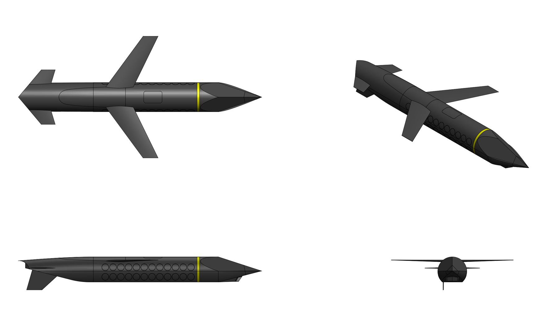
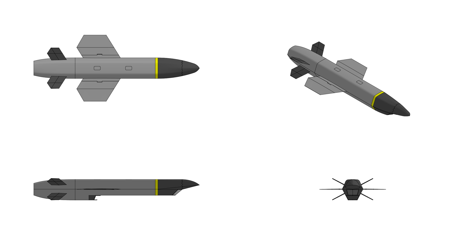
RBS 115 Halosaur


General Characteristics:
Type:
Standoff anti-submarine missile

Launch platform:
Torpedo tube, VLS

Guidance:
INS

Physical Characteristics:
Weight:
2,000 kg

Length:
7.0 m

Diameter:
0.6 m (capsule diameter)

Warhead:
Performance Characteristics:
Propulsion:
Solid fuel rocket

Speed:
Mach 2.5

Launch Depth:
up to 250 m

Range:
5 - 150 km


Overview:
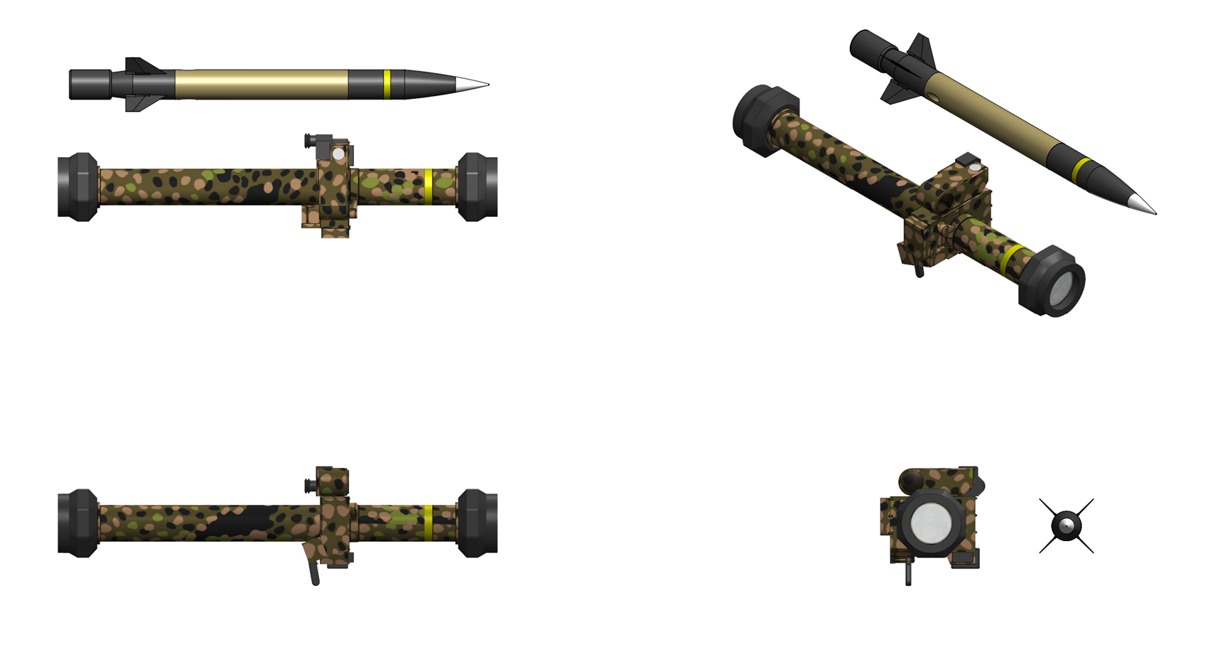
The RBS 115 Halosaur is a long range standoff anti-submarine missile designed by SDI Missile & Fire Control Systems. The RBS 115 is available in two versions, an RBS 115S variant designed to be launched from SDI’s S70 surface ship VLS and an RBS 115U version intended to be launched from the 60 cm torpedo tubes on SDI’s Hydra and Erebus class submarines.


Airframe & Propulsion:
The RBS 115 missile consists of a single stage solid fuel rocket booster with a thrust vector control (TVC) system connected to a payload section containing an SDI F3S Viperfish lightweight anti-submarine torpedo with a ballistic nosecap and a stabilizing parachute assembly. A conical adapter section between the rocket motor and payload sections contains the missile’s inertial navigation system and guidance electronics. The missile’s rocket motor is 55 cm in diameter and 3.5 meters long and is constructed from filament wound graphite epoxy composite. The motor weighs 1,200 kg including 1,000 kg of SDI minimum-smoke insensitive tactical propellant consisting of 25.5% GAP energetic binder, 4.5% TMETN (trimethylolethane trinitrate) plasticizer, 58.5% ADN (ammonium dinitramide) oxidizer, and 11.5% HMX (Octogen) combining high isp and burn rate, low impact and thermal sensitivity, and low exhaust signature The rocket motor burns for 25 seconds with a peak thrust of 100 kN, accelerating the missile to a burnout velocity of over Mach 2.5 (750 m/s). The rear of the rocket motor includes four flip out tail fins for stabilization and is steered during rocket motor burn by a turbo-hydraulic thrust vector control system with a hydraulically actuated ball joint nozzle with +\- 10° thrust vector capability. Post rocket motor burn the missile is steered by the four flip out tail fins which are actuated by electromechanical servo actuators powered by a thermal battery that activates at launch.

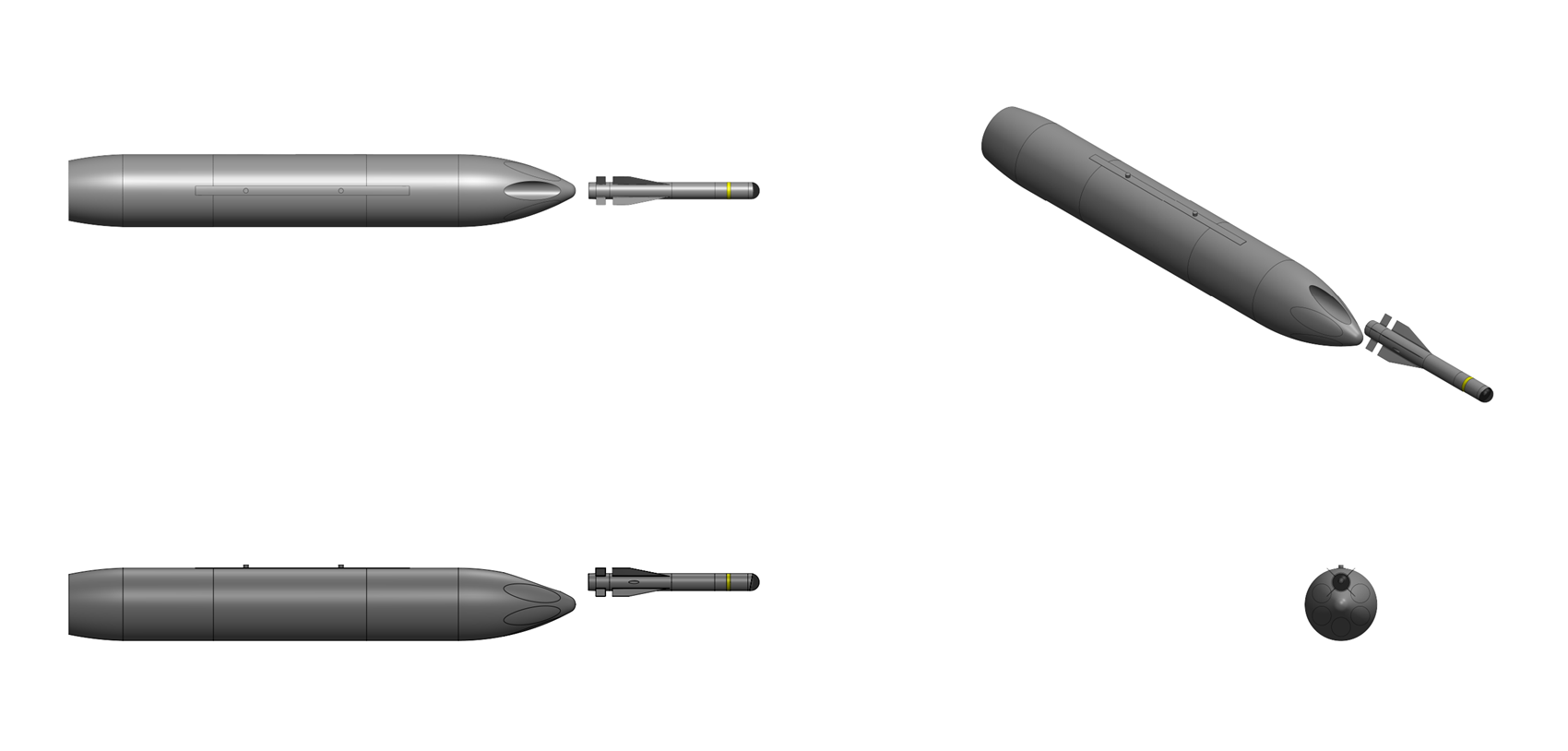
When launched from submarine torpedo tubes the missile assembly also includes a watertight composite capsule surrounding the missile which provides environmental protection during submerged launch from a submarine torpedo tube and buoyancy to bring the weapon to the surface before the rocket motor fires. The capsule is a cylindrical pressure vessel fabricated from wound graphite-epoxy with hemispherical end caps.The capsule is designed to withstand hydrostatic pressure at a maximum launch depth of 250 meters. The interior is filled with a nitrogen atmosphere at slightly above ambient pressure to prevent moisture intrusion. The missile is supported within the capsule by shock-mounted cradles that attenuate the impulse loads during torpedo tube ejection. The forward end of the capsule contains a pyrotechnically-actuated nose cap jettison system, and the aft end contains a buoyancy management system. The launch capsule is designed with positive buoyancy sufficient to ensure reliable ascent to the surface after ejection from the torpedo tube. Closed-cell syntactic foam panels are bonded to the interior walls of the capsule to provide the required buoyancy margin. The capsule’s center of buoyancy is positioned forward of and above its center of gravity to ensure a stable, nose-up ascent attitude as it rises through the water column. The capsule incorporates a hydrostatic pressure sensor and a surface-detection system consisting of a conductivity sensor and an accelerometer array. As the capsule breaches the surface and the rate of ascent slows, the surface-detection system confirms arrival at the air-water interface. The system includes a programmable delay timer (nominally 1.5 seconds) to allow transient wave wash to subside before committing to the launch sequence.


Guidance
The RBS 115 missile features an SDI fiber-optic gyro based guidance unit which provides missile navigation, guidance, autopilot, payload dispensing, and communications functions for the missile in a low size and compact package. The RBS 115 guidance set provides the navigation, guidance, autopilot, and launch platform communications functions for the missile while in flight and for all shipboard operations. A control sensors unit in the control & guidance electronics section includes an SDI TNS 200 fiber-optic gyro inertial measurement unit which inputs 6-axis guidance and control information to the missile guidance unit processors and consists of a strapdown unit with 3 fiber-optic gyros and 3 MEMS quartz accelerometers with <0.1°/hr bias and <0.008°/√hr random angle walk. Continuous determination of missile position, attitude, and velocity from the IMU is output to the autopilot and guidance software to make the missile operation function as a closed loop system. A dual CPU unit is the core of the missile guidance unit and consists of two SDI SPPC9D single-board computer, a ruggedized, shock hardened computer which employs POWER9 architecture with a cluster of four conduction-cooled 4.0 gHz quad-core superscalar symmetric multiprocessors and 64 megabytes of DDR5 magnetoresistive random access memory MRAM. Missile guidance tasks are divided between the two processors, one used to handle control of data collection from the inertial sensors and the other to performs the navigation, autopilot, guidance, and communications processing.


Warhead
The payload of the RBS 115 consists of an F3S Viperfish torpedo, a modern lightweight torpedo designed by SDI Underwater Systems specifically to engage and destroy high-speed, deep diving submarines. The Viperfish features a combined active and passive sonar seeker, a closed cycle propulsion system that provides high speed and depth independent performance, and a shaped charge warhead capable of penetrating into large double hulled submarines. dropped from the rocket at a precalculated point on its trajectory, and then parachuted into the sea.


Flight Sequence
For submarine launch the encapsulated RBS 115 is loaded and fired like a conventional torpedo. Following ejection from the torpedo tube the missile continues forward for several meters until an umbilical breakwire connecting the missile to the torpedo tube is severed, causing the capsule to turn vertically and rise towards the surface. The capsule transits to the surface under its own buoyancy, with the onboard electronics in a low-power standby mode powered by a primary lithium battery. When an accelerometer inside the missile detects that the capsule has breached the surface the nose of the capsule is explosively ejected and the missile’s rocket motor is ignited, accelerating the missile out of the capsule and toward the target area. The empty capsule is left floating on the surface and will scuttle via a timed seawater flood valve within 15 minutes to avoid leaving a surface signature. Following rocket motor burn the missile coats on a ballistic trajectory toward the target area. As the missile approaches the target area a set of drag flaps on the center adapter section are extended, slowing the missile to subsonic speeds. Upon reaching the computed release point, the flight computer commands the separation sequence where the nose section is jettisoned by explosive bolts, the forward payload bulkhead separates, and a gas-actuated piston pushes the torpedo forward and clear of the missile body. A drogue-deployed parachute system, stowed in a compartment immediately aft of the torpedo within the payload section, deploys automatically upon torpedo separation. When the torpedo hits the water it’s aerodynamic nose cap shatters and it’s parachute detaches before it’s propulsion system is activated and it begins it search pattern.
Last edited by The Technocratic Syndicalists on Wed May 13, 2026 5:47 pm, edited 20 times in total.
SDI AG
Arcaenian Military Factbook
Task Force Atlas
International Freedom Coalition


OOC: Call me Techno for Short
IC: The Kingdom of Arcaenia

User avatar
The Technocratic Syndicalists
Minister
 
Posts: 2349
Founded: May 27, 2015
Inoffensive Centrist Democracy

Postby The Technocratic Syndicalists » Wed Oct 28, 2020 11:49 am

Image


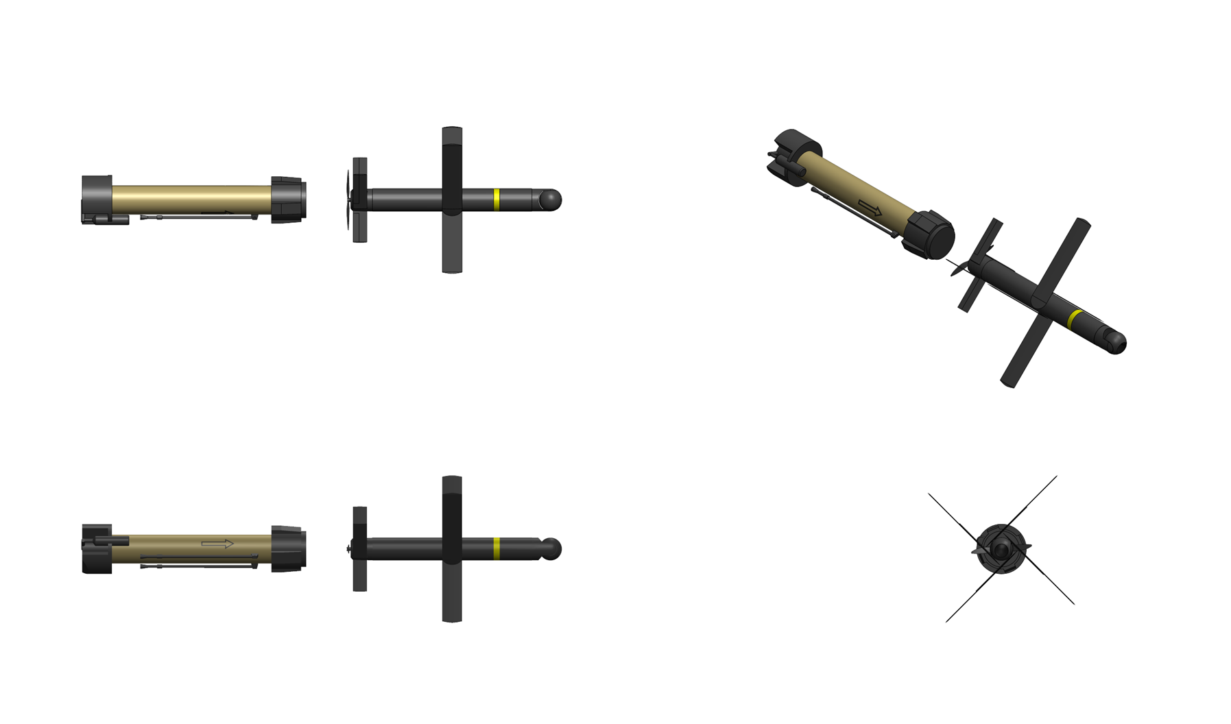
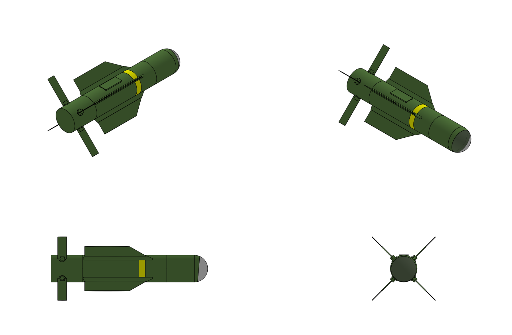
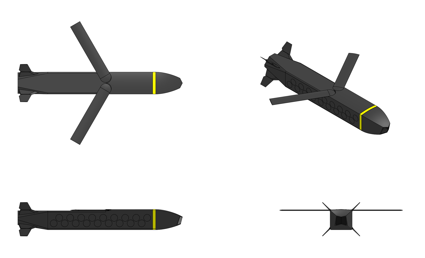
DWS 1000


General Characteristics:
Type:
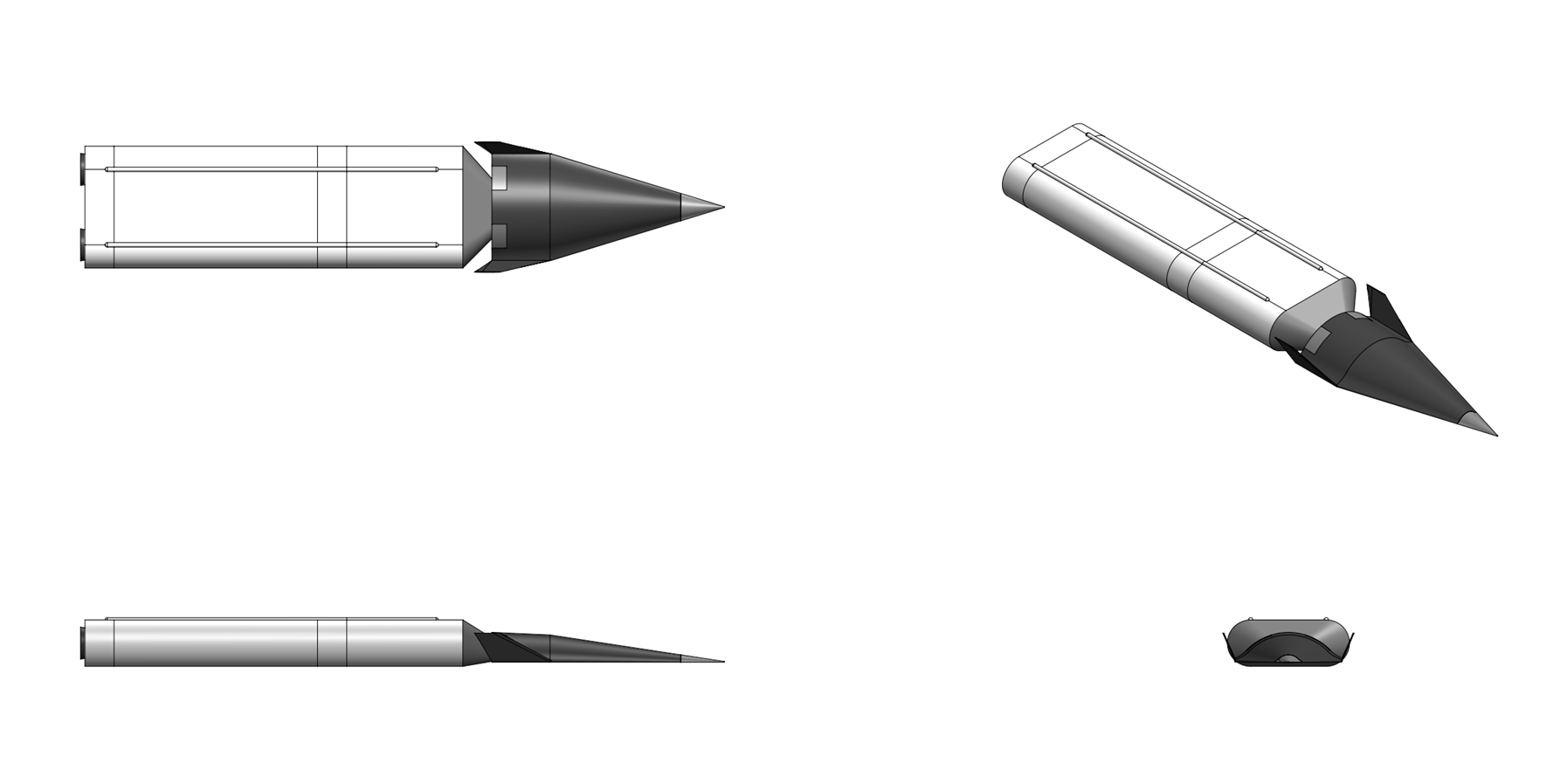
Guided cluster bomb

Launch platform:
Aircraft

Guidance:
INS/GPS, Imaging infrared (IIR)

Physical Characteristics:
Weight:
1,000 kg

Length:
4.1 m

Diameter:
0.55 m

Payload:
36x ZEPL sensor fuzed anti-armor submunitions


Performance Characteristics:
CEP:
<3 m

Range:
130 km (Mach 0.9 release @ 12,000 meters


Overview:
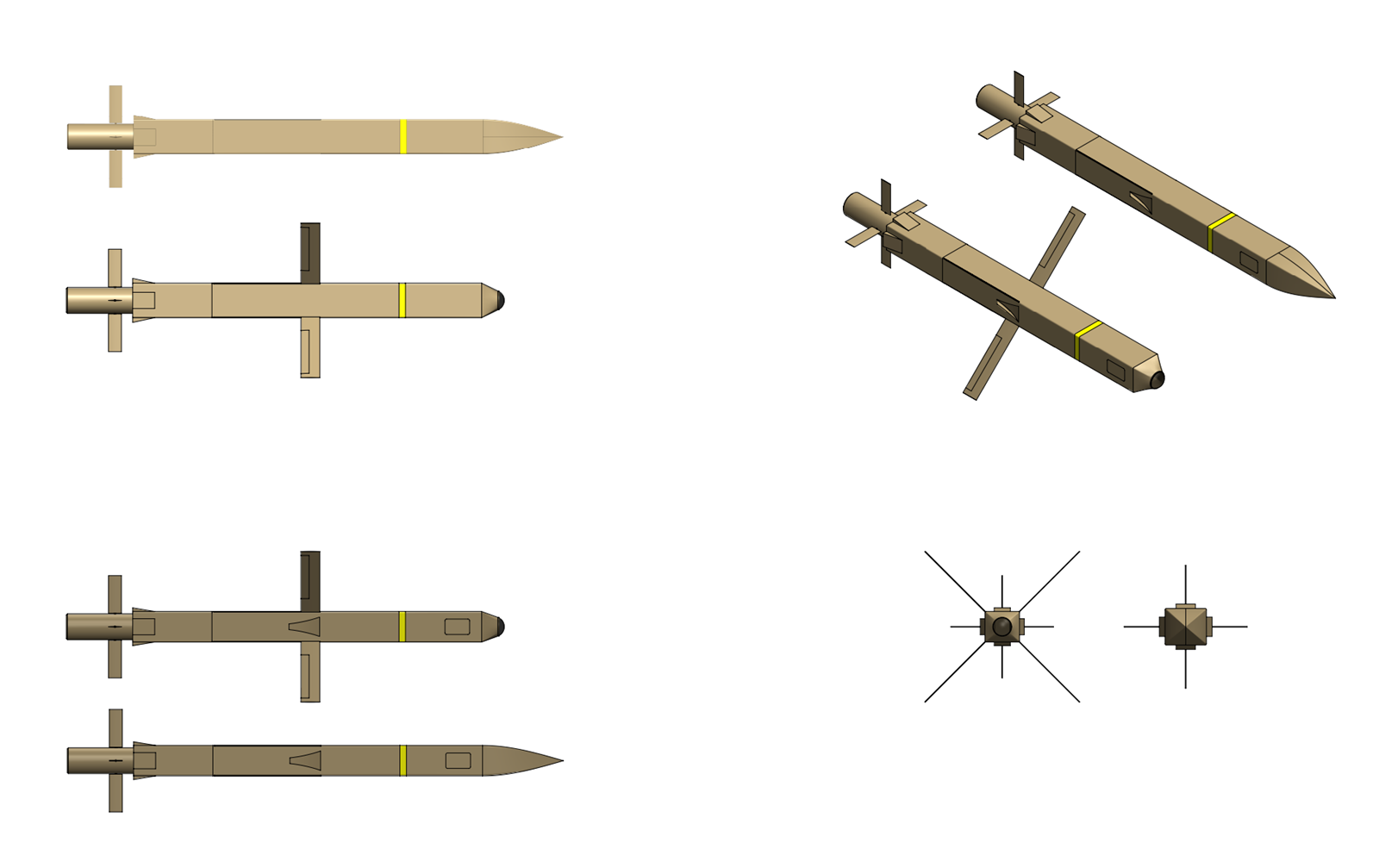
The DWS 1000 is an autonomous standoff guided cluster glide bombs which designed to enable standoff attacks against armor, air defense, and airfield targets outside the range of short and medium range air defense systems. The DWS 1000 integrates a low-observable glide body with a payload of autonomously guided anti-armor submunitions, integrated with a ] single forward-looking imaging infrared (IIR) sensor that serves triple duty as a terrain-referenced navigation aid, a wide-area search sensor, and a terminal autonomous target recognition (ATR) engine The weapon is designed to defeat concentrations of main battle tanks (MBTs), infantry fighting vehicles (IFVs), self-propelled artillery, air-defense vehicles, and other armored assets in contested electromagnetic environments.


Airframe:
The DWS 1000 consists of a rectangular shaped unpowered glide body divided into three sections; a a faceted nose fairing that houses the weapon's imaging infrared seeker and guidance electronics, a rectangular center section with two fold out glide wings and the weapons cluster munition payload, and a tail section with four aerodynamic tail control surfaces actuated by an electro-mechanical tail control system. Virtually the entire weapon including the nose fairing, fuselage, wings, tail, and tail fins is constructed from vacuum assisted resin transfer molded (VARTM) graphite/epoxy and glass/epoxy composite which results in a low structural weight and along with the weapon's lack of propulsion results in a low radar cross section and infrared signature. The radar cross section of the weapon is further reduced with radar-absorbing material (RAM) integrated into the outer mold line and with joint panels employing saw-tooth edge treatments to scatter radar returns away from threat receivers.

The weapon's wing group consists of two single-panel, high-aspect-ratio wings that fold aft against the body for stowed carriage and deploy to the flight position within 1.5 seconds of release via redundant torsion-spring actuators with pyrotechnic backup. The wing planform is moderately swept (30° leading-edge sweep). The wing airfoil is a custom laminar-flow section with a thickness-to-chord ratio of 8%, optimized for the Reynolds-number regime at glide speeds of Mach 0.65–0.85. When deployed wing aspect ratio of 8.2:1 yields a predicted maximum L/D of approximately 12:1 at best-glide speed, enabling stand-off ranges in excess of 100 km from a 6,000 meter release altitude and 130 km from high-altitude (12,000 meter) releases. Flight control is achieved through a set of X-tail control surfaces with four tail control surfaces canted at 45° from the vertical. This arrangement avoids the strong broadside RCS return of conventional vertical fins while providing combined pitch, yaw, and roll authority. Each surface is individually actuated by an electromechanical actuator (EMA) and functions as a combined elevator/rudder.


Guidance & Navigation:
The DWS 1000 is guided by a combination INS/GPS midcourse guidance system and a scanning imaging infrared seeker in the nose of the munition which is used for target detection and automatic target recognition (ATR), submunition cueing, and point to point image-based terrain reference navigation. The weapon's midcourse guidance unit (MGU) consists of an SDI TNS 570 tactical inertial measurement unit, a C band LPI (Probability of Intercept) radar altimeter, and a GPS receiver system. The TNS 570 is an enhanced 6-axis resonator fiber optic gyro (RFOG) based tactical inertial measurement unit designed by SDI Missile Systems and consists of three resonator fiber optic gyros and three monolithic quartz structure vibrating beam accelerometers contained a compact, low SWaP (750 cc volume, <1.5 kg mass, <10 watts max power consumption) package which provides aircraft gyrcocompass based performance with <0.003°/√hr gyro angle random walk and <0.1 °/hr bias stability in a tactical munition IMU size form factor. The TNS 570 IMU is coupled to a 48 channel dual-frequency (L1/L2) SAASM (Selective Availability Anti-spoofing Module) based GPS receiver with M-Code compatibility and >90 dB J/S digital anti-jamming capability. The GPS system employs twin controlled reception pattern antennas (CRPAs) with adaptive beam steering and directional nulling capability located on either side of the munition's tail control section which along with ionosphere correction capability provided simultaneous L1/L2 operation provides the weapon with <2 meter position accuracy in heavy GPS jamming environments. The flight management computer is a dual-redundant, radiation-tolerant, multi-core processor based on a COTS-derived architecture packaged for the military environment. It executes the navigation EKF, guidance laws, TRN correlation, flight-control servo loops, and dispensing logic. The ATR inference pipeline runs on the dedicated GPU module but receives tasking and reports target data to the mission computer over a high-speed internal data bus. Total processing throughput exceeds 50 GFLOPS for the mission computer, with the ATR GPU providing an additional 30+ TOPS of inference capacity.

The weapon's seeker consists of a cooled 1280 × 1024 element,12 μm pixel pitch HgCdTe FPA imaging infrared (IIR) seeker operating in the MWIR (3– 5 µm) band which is mounted in the nose of the weapon behind a faceted optical window. The sensor has a 10° instantaneous field of view and is mounted to a 2-axis stabilized gimbal driven by twin limited angle torque motors (LTA) which gives the seeker +/- 45° pointing capability in azimuth and +10°/- 30° in elevation. The sensor is stabilized to the horizon using the 2-axis gimbal system with a strap-down stabilization algorithm which takes angular weapon position inputs from the IMU and gimbal position inputs from the encoders in the gimbal motors to command the gimbal torque motors to keep the seeker stabilized along the horizon as the weapon banks and maneuvers. The sensor has two fields of view, a 12° × 9.6° Wide FOV used for initial search and a 3° × 2.4° Narrow FOV used for ATR. The sensor is located behind a faceted germanium window set into the nose of the munition which is edge aligned with the primary planform edge sweep. The outer surface includes a diamond-like carbon (DLC) protective coating for rain and particle erosion resistance. The sensor serves three functions across the flight profile: terrain-referenced navigation during midcourse flight, wide-area target search during target-area ingress, and fine-resolution target classification and aimpoint selection during the terminal engagement phase. While enroute to the target area the IIR sensor captures a sequence of georeferenced ground images during flight. Each image is processed to extract a thermal-contrast terrain feature map, which is then correlated against a pre-stored Digital Terrain Reference Database. The DTRDB contains geo-registered IR scene templates generated from elevation data (DTED Level 2), land-use classification, thermal modeling of terrain materials, and historical IR imagery. Correlation is performed using a multi-resolution normalized cross-correlation algorithm accelerated on the onboard GPU. When a high-confidence match is obtained (correlation coefficient ≥ 0.85), the resulting position fix is fed to the navigation extended Kalman filter (EKF) as a measurement update. A deep convolutional neural network (CNN) trained on diverse IR terrain imagery provides a complementary TRN capability, the CNN extracting learned feature descriptors from the live IIR image and matching them against descriptors pre-computed from the reference database. This mode is more robust than the area correlation mode in conditions of significant thermal variation (e.g., seasonal differences between the reference imagery epoch and the mission date) and in terrain with low inherent relief but distinctive cultural features (roads, buildings, field boundaries). The CNN feature matcher operates on the same GPU as the ATR processor and shares the inference pipeline and is trained on a dataset of over 10 million paired IR scenes spanning diverse geographies, seasons, and times of day, using a contrastive learning architecture that produces position-invariant feature embeddings.

The sensor's ATR system is a deep-learning-based, multi-stage target detection, classification, and aimpoint-refinement pipeline implemented on a ruggedized, low-power GPU accelerator module. The ATR system runs on an embedded GPU accelerator based on commercial radiation-hardened silicon. The processing module provides 30+ TOPS (tera-operations per second) of INT8 inference throughput in a 40 W power envelope. The module is packaged in a sealed, conduction-cooled enclosure mounted in the avionics bay, sharing a thermal bus with the mission computer. The ATR operates continuously from target-area ingress through submunition dispensing and provides target cueing data to the flight management computer for dispensing optimization. The pipeline consists of three cascaded stages: Detection, Classification, and Aimpoint Refinement. During the detection stage a lightweight convolutional neural network rapidly scans each wide-FOV sensor frame to identify regions of interest that contain potential vehicle-sized thermal signatures above background clutter. This stage operates at full frame rate (60 Hz) and is designed for very high probability of detection (Pd ≥ 0.99) at the cost of moderate false-alarm rate. In the Classification stage each target candidate ROI is extracted, normalized, and processed through a deeper classification CNN that assigns a target-class label (MBT, IFV, APC, SP artillery, SHORAD, wheeled logistics, non-target) and a confidence score. Only candidates exceeding a tunable classification threshold (default: 0.90) are forwarded as confirmed targets. The classifier is trained on a dataset of over 2 million labeled IR vehicle signatures across diverse environmental conditions, aspect angles, and occlusion states. For confirmed targets, a specialized aimpoint-selection network then identifies the optimal attack point and refines the target’s georeferenced coordinates for handoff to the submunition dispensing algorithm. This stage also estimates target heading and velocity for lead computation if the target is moving. The entire ATR system maintains a real-time target track file of all detected and classified targets within the search area. As the weapon overflies the target area, the FMC and ATR cooperate to solve the assignment problem: mapping the 36 available submunitions to the highest-priority targets in an engagement sequence that maximizes total expected kills while avoiding wasted shots. The assignment algorithm accounts for target class priority (MBTs first, then IFVs, etc.), geometric accessibility (flyover angle), submunition footprint deconfliction (minimum spacing to prevent two submunitions from acquiring the same target), and confidence level weighting. The engagement logic supports both autonomous mode (fully automated target selection and dispensing) and constrained mode (weapon engages only within a geofenced target area and/or only targets matching specified class filters loaded during mission planning).


Warhead:
DWS 1000A: The DWS 1000A contains a payload of 36 ZEPL sensor fuzed anti-armor submunitions and is optimized for attacking convoys of armored vehicles. The submunitions are contained in 36 sideways facing launch tubes (18 per side) each containing a single submunition and a gas generator expulsion system, allowing submunitions to be individually ejected against multiple targets along either side of the weapon's flight path. Each ZEPL submunition is a cylinder 175 mm in diameter and 205 mm long with a launch weight of 18.75 kg and consists of a parachute retarding system, a tri mode active 94 GHz MMW radar/passive 94 GHz MMW radiometer/passive IR target detection sensor, and a multiple EFP warhead which is bore sighted with the target detection system. Following ejection from the weapon the ZEPL deploys a drogue parachute to slow its descent where a second vortex ring parachute then deploys which slowly spins the submunition and suspends it at approximately 30° angle from the vertical where the MMW and IR sensors scan across a decreasing spiral track beneath the submunition, scanning an area about 200 meters in diameter along the ground. The target detection sensor matches objects detected during its scan with an on-board threat-library. When the sensor detects and confirms an armored target signature within the scan footprint, the onboard processor computes firing time based on the target’s position relative to the scanning EFP axis. The tri-mode sensor provides discrimination against decoys and non-target objects through independent radar and IR confirmation. The EFP warhead contains a 2.0 kg polymer bonded HMX explosive (95% HMX, 3% BDNPA/F, 3% estane) charge and features a central concave tantalum liner forming the center single EFP (SEFP) which is surrounded by 16 smaller tantalum multiple-EFPs (MEFPs) which creates a shotgun-like blast of smaller EFPs to increase lethality against unarmored or lightly armored vehicles. The main SEFP has a 50 centimeter dispersion at a range of 100 meters and is capable of penetrating over 150 mm of RHA at the same distance, sufficient to punch through the roof armor of most tanks and other armored vehicles. At the computed time, the EFP warhead fires, projecting a high-velocity tantalum slug downward into the target’s top armor. The EFP reaches peak velocity of approximately 2,500 m/s and forms a penetrator capable of defeating the roof armor of almost all known MBTs. Should the submunition fail to find a target the submunition is programmed to self-destruct at an altitude of 10 meters with additional backup impact and electronic time self destruct fuzes.


Flight Sequence:
Prior to the mission, mission planning software generates the weapon’s flight plan including release point, ingress waypoints optimized for TRN availability, target area boundaries, ATR class-filter settings, and engagement rules (e.g., geofence constraints, minimum classification confidence). TRN reference imagery sets are selected from the database for the planned route and loaded to the weapon. The launch aircraft approaches the release point at medium to high altitude, potentially at stand-off distances of 100+ km from the target area, remaining outside the engagement envelopes of medium-range SAM systems. The pilot designates the target area (or confirms the pre-planned target area), confirms weapon settings, and releases. The weapon separates, deploys wings and tail, and begins its autonomous glide. During the glide, the weapon navigates using the INS/GPS/TRN blend. If GPS is jammed—as is expected in a peer-conflict scenario—the weapon relies on INS corrected by TRN. The pilot is free to egress or re-attack with other weapons immediately after release. As the weapon approaches its designated target area it descends to an altitude of around 500 meters using its radar altimeter where the seeker is used in a pushbroom scan mode to sweep back and forth along either side of the weapon's ground track to scan for targets. Images from the IIR seeker are processed using the ATR processor in the weapon's guidance electronics section which provides real-time autonomous target recognition (ATR) and sensor management capability. Potential targets in the scene are first ranged using using radar altimeter inputs, infrared sensor elevation angle, and stored digital map data. Once a target or set of targets has been identified the weapon will initiate ejection of one or more submunitions from either side of the weapon to attack the target. The dispensing sequence is managed by the FMC in coordination with the ATR system. The FMC computes the optimal release point for each submunition based on the weapon’s current ground track, altitude, airspeed, target positions, and wind estimates. Submunitions can be dispensed individually or in ripple sequences (pairs or triplets) depending on target density and distribution. The minimum interval between successive ejections from the same side is 0.3 s, allowing the weapon to dispense all submunitions across a footprint spanning up to 1,200 m of ground track at typical glide speeds. If the ATR detects more than 36 targets, the engagement algorithm prioritizes by target class and confidence score, selecting the 36 highest-value targets for engagement.
Last edited by The Technocratic Syndicalists on Mon May 11, 2026 12:14 pm, edited 30 times in total.
SDI AG
Arcaenian Military Factbook
Task Force Atlas
International Freedom Coalition


OOC: Call me Techno for Short
IC: The Kingdom of Arcaenia

User avatar
The Technocratic Syndicalists
Minister
 
Posts: 2349
Founded: May 27, 2015
Inoffensive Centrist Democracy

Postby The Technocratic Syndicalists » Sun Nov 15, 2020 9:11 pm

Image


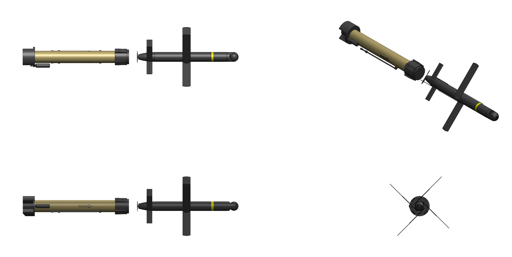
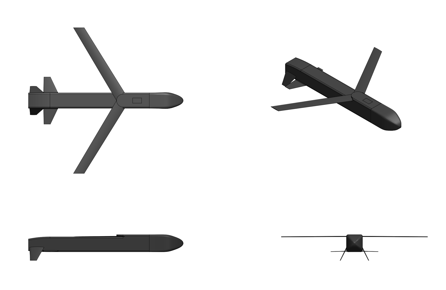
Sparrowhawk 100


General Characteristics:
Type:
Autonomous loitering munition

Launch platform:
Portable launch tube

Guidance:
IR/EO, INS/GPS

Physical Characteristics:
Weight:
9.0 kg (munition), 12.0 kg (with launch canister)

Length:
1.2 m

Wingspan:
0.8 m

Warhead:
1.5 kg blast-fragmentation

Performance Characteristics:
Propulsion:
Electric motor

Maximum speed:
80 knots

Cruise speed:
60 knots

Range:
40 km

Endurance:
45 minutes


Overview:
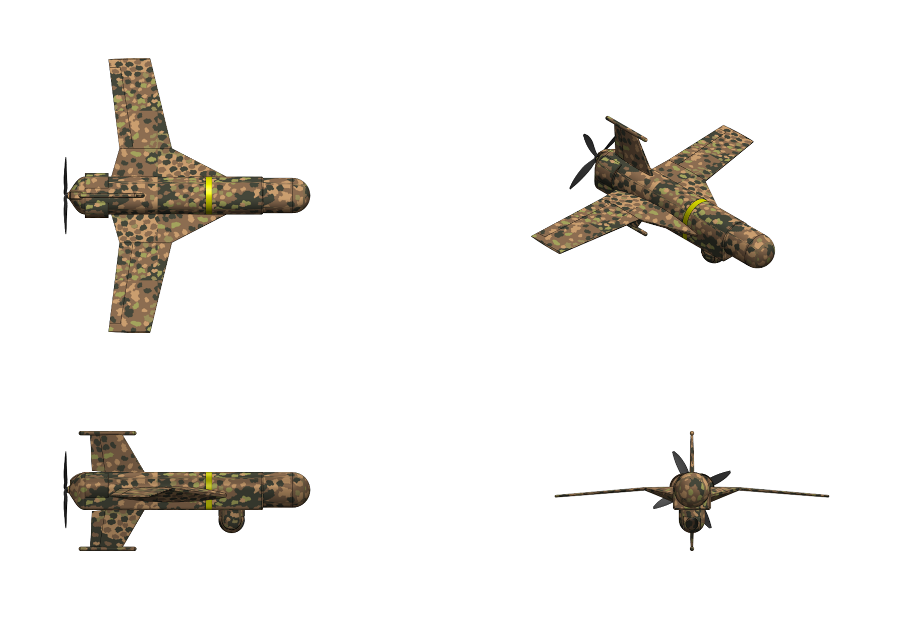
The SDI Sparrowhawk 100 is a lightweight, tube launched, fully autonomous loitering munition designed by SDI Missiles & Fire Control System designed for employment against tactical targets in GPS-denied, communications-degraded, and electronically contested environments. Unlike operator-in-the-loop systems Sparrowhawk family of munitions are designed to operate with full onboard autonomy from launch to terminal engagement, requiring no sustained datalink or human piloting after deployment. The Sparrowhawk 100 is packaged inside of a man portable self-contained launch tube assembly (LTA) which contains the munition and a pneumatic ejection system which deploys the munition from the tube. The Sparrowhawk munition itself possesses up to a 45 minutes of flight endurance using an electric propulsion system with a low infrared and aural signatures and carries a multi-spectral electro-optical targeting sensor suite along with a pre-formed fragment blast fragmentation warhead effective against light vehicles, personnel, and materiel targets. The complete Sparrowhawk 100 munition system consists of a case containing twin launch tube assemblies and another case containing a touchscreen tablet based fire control unit (FCU) and a portable omni-directional datalink antenna system.


Airframe & Propulsion:
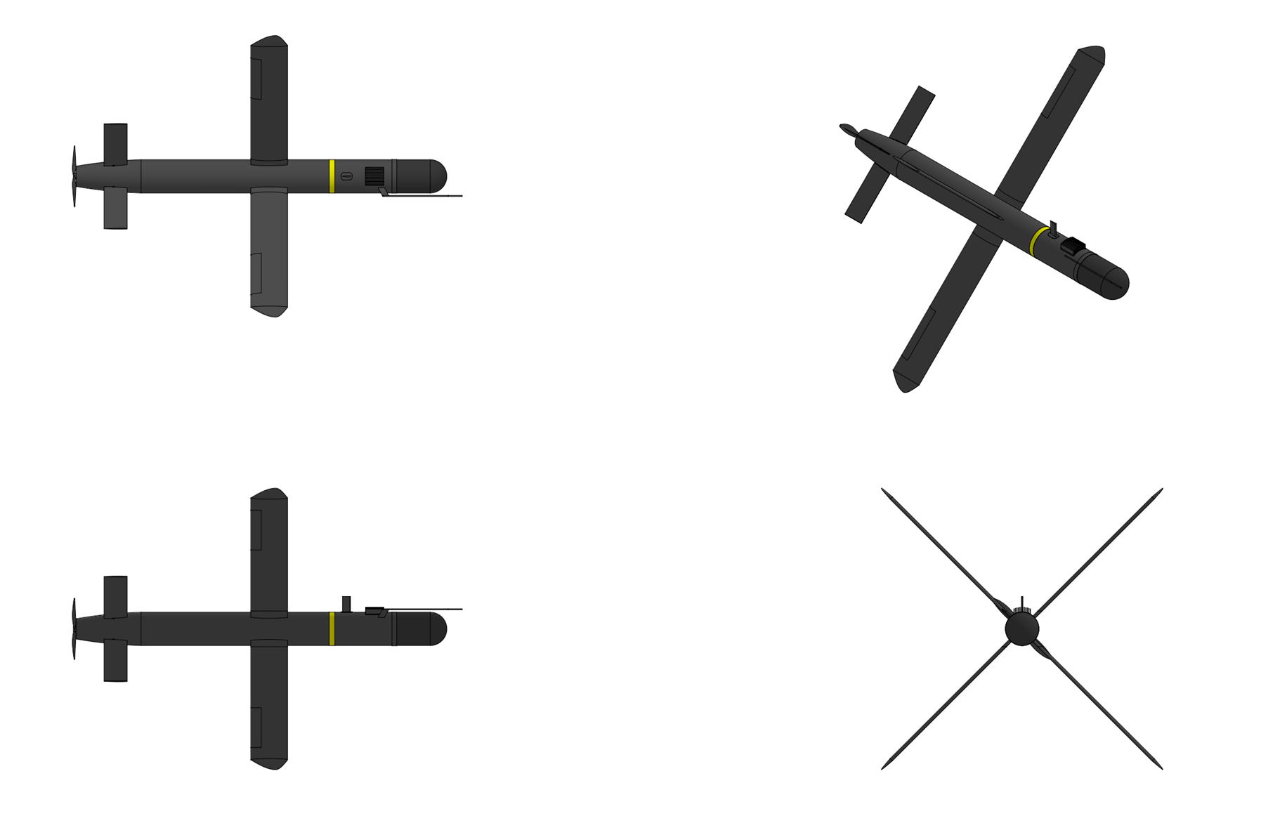
The Sparrowhawk 100 munition features a cylindrical fuselage 9.0 centimeters in diameter and 100 centimeters long constructed from graphite/epoxy composite. The rear of the munition contains the propulsion section with a low-acoustic-signature brushless permanent-magnet electric motor driving a two bladed composite pusher propeller, the munition having a design cruise speed of 60 knots (110 km/h) and a maximum terminal speed of 80 knots (145 km/h). The electric motor is supplied electricity by a high power density thermal battery located inside the missile's midsection which gives the munition a flight time of up to 45 minutes. Lift is provided by four flip-out cruciform wings mounted to the midsection of the missile which spring out after the munition is ejected from the launch tube assembly. Steering is provided by four rear flip-out tailfins actuated using an electro-mechanical control actuation system (CAS) powered by the missile's thermal battery. The nose of the munition contains the electro-optical sensor suite with a two-sensor 2-axis stabilized gimbal along with the missile's inertial measurement unit, GPS receiver, and digital autopilot system. The missile's warhead employs a main charge with a tungsten fragmentation liner which is located behind the thermal battery


Guidance & Control:
The Sparrowhawk 100 is equipped with a 2-axis stabilized gimballed electro-optical sensor suite with two sensors; a 1280 x 720 pixel pixel color CCD imager with variable 13.7° – 1.2° field of view and 12x electronic zoom, and an uncooled 640 x 512 pixel LWIR (long-wave infrared) imager with variable 24.1° - 12.1° FOV and 3x electronic zoom. Detection ranges for a man sized target are approximately 5.5 km with the electro-optical sensor and 1.5 km for IR. The sensor head features +30° to -90° tilt capability and capable of rotating a full 360° with 2-axis active stabilization and 6-axis vibration isolation from the missile body. Midcourse guidance capability is provided by a 6-axis strapdown inertial measurement unit (IMU) containing a 3-axis fiber optic gyro assembly and 3-axis MEMS (Micro Electro Mechanical System) silicon accelerometer which is coupled to a GPS unit with a 24 channel SAASM (Selective Availability Anti-spoofing Module) based anti-jam GPS receiver. The munitions' onboard GPS-aided INS is co-located with the twin cameras and allows the gimbal to be used to provide real-time geopointing and geolocation for targeting. Advanced embedded video processing features include AI enabled scene and target tracking tracking using SDI's "Sentient" AI-powered object detection and tracking software which runs on a ruggedized, low-power edge AI processor. Sentient runs on an embedded SDI Lattice GPGPU AI supercomputer, a low SWaP (Size, Weight, and Power) AI edge computing module with 275 TOPS of INT8 performance and 64GB of LPDDR5X memory. Sentient is designed to detects and identify targets and other objects of interest in the the sensor feed using machine learning algorithms trained on a library of multispectral data for both search characteristics and feature extraction and detects both stationary and moving objects including vehicles, people, and weapon systems in complex terrain and environments. Sentient is capable of detecting objects as small as 2x2 pixels with persistent tracking functionality that separate tracks for each detected object even when they overlap or pass behind temporary obstructions. For terminal homing Sentient supports closed loop, perception driven automatic target recognition (ATR) capability and autonomy homing with advanced search, 3D aimpoint selection, and terrain aware operations. Sentient's pixel lock targeting capability enables precise, persistent reidentification tracking of detected targets through signal degradation or loss when executing fully autonomous missions.

The sensor suite of the munition also employs SDI's HydraNav optical-navigation system for GPS-independent midcourse guidance. HydraNav combines the munition's electro-optical sensor with SDI's HydraVision real-time 3D mapping software and computes both absolute and relative navigation position updates through the fusion of three different HydraVision algorithms: a Stereo Terrain Correlation algorithm which captures overlapping images along the missile's flight path using the onboard FLIR and then correlates the real-time generated stereo elevation model with stored terrain references for precise geo-location determination, an Image-Based Feature Matching algorithm which matches image features in captured imagery with stored terrain image references, providing additional navigation location, and a Feature-Based Velocity Estimation algorithm which tracks image features from frame to frame to constrain inertial navigation system drift between HydraNav position updates.

Following launch the Sparrowhawk is designed to navigate towards the target area using a combination of INS/GPS and the munition's HydraNav terrain reference navigation system. Upon entering the designated target search area (defined by the operator at launch as a geographic polygon), the Sparrowhawk munition autonomously executes an optimized search pattern, a modified expanding-square or sector scan adapted in real-time based on terrain and assessed threat detection probability. The Sentient AI then continuously processes sensor data to detect, classify, and prioritize potential targets. Sentient's deep convolutional neural network (CNN) trained on military vehicle and equipment datasets then performs target classification, the model is designed to distinguish between vehicle classes such as main battle tanks, infantry fighting vehicles, self-propelled artillery, air defense systems, logistics vehicles, and static installations. Sentient's classifier then outputs a confidence score and a target-type label for each detected target. Sentient's onboard decision engine then evaluates detected targets against a pre-loaded engagement rule set defined by the operator before launch which specifies authorized target categories, geographic boundaries (no-engage zones), and minimum classification confidence thresholds. Once a suitable target has been selected the munition will then commit to a terminal attack dive if all engagement rule-set conditions are satisfied. Once committed, the munition then enters a steep terminal dive, switching to a high-refresh-rate tracking mode using fused IR/EO imagery where an aim-point selection algorithm identifies the most vulnerable point on the target to maximize warhead damage. The control system then guides the munition to impact, switching from bank-to-turn control to skid-to-turn control to increase the munition's terminal maneuverability. Precision terminal accuracy keeps collateral damage to a minimum (less than 1 CEP). If the munition fails to acquire a target it will automatically self-destructs if it fails to locate a target within its designated engagement area or if it passes through its predefined "kill box" without acquiring a valid target.

Although designed to operate primarily autonomously the Sparrowhawk can also be manually controlled in first-person view (FPV) mode using a 2-way datalink system which connects the munition to the touchscreen tablet based fire control unit (FCU). In first-person view (FPV) mode imagery from the sensor suite is transmitted using an L band (1,625MHz to 1,725 MHz) encrypted data link system at up to 4.5 Mbps to the system's tablet based fire control unit (FCU) through a portable data link antenna connected to the tablet. In FPV mode the munition's AI software runs in the background, highlighting objects of interest in the sensor scene which are surrounded by a color coded box which includes the detected target probable identification with a real time updating confidence interval assessment. The datalink system also allows for mid-mission attack adjustment when the munition is used autonomously, including options to adjust or change target search areas, change target priorities, or abort the attack and safely disarm and crash the munition. A low-bandwidth telemetry link also provide periodic status updates (munition position, battery state, search status) to the operator.


Warhead & Fuzing:
The Sparrowhawk 100 features an internal 1.5 kg blast-fragmentation warhead which is intended to be effective against personnel and light vehicle and materiel targets. The warhead is pre-formed fragment (PFF) type warhead consisting of an outer pre-formed fragmentation sleeve containing 3,000 3mm diameter tungsten spheres in an epoxy resin matrix surrounding a central explosive charge consisting of 300 grams of cast polymer bonded explosive (90wt% HMX, 10wt%. HTPB-based binder). An additional 40 gram Zirconium ring is placed around the base of the the explosive charge around the warhead's 2.0 gram RDX booster charge, adding an additional incendiary effect to the warhead. The warhead has comparable lethal area to an 81mm high explosive mortar round and is effective against crew served weapons, unarmored vehicles, and other light targets. The warhead can be detonated in one of three modes; contact, delay, or airburst using a laser height-of-burst sensor built into the forebody of the munition.
Last edited by The Technocratic Syndicalists on Wed Apr 08, 2026 6:17 am, edited 13 times in total.
SDI AG
Arcaenian Military Factbook
Task Force Atlas
International Freedom Coalition


OOC: Call me Techno for Short
IC: The Kingdom of Arcaenia

User avatar
The Technocratic Syndicalists
Minister
 
Posts: 2349
Founded: May 27, 2015
Inoffensive Centrist Democracy

Postby The Technocratic Syndicalists » Mon Nov 23, 2020 3:21 pm

Image


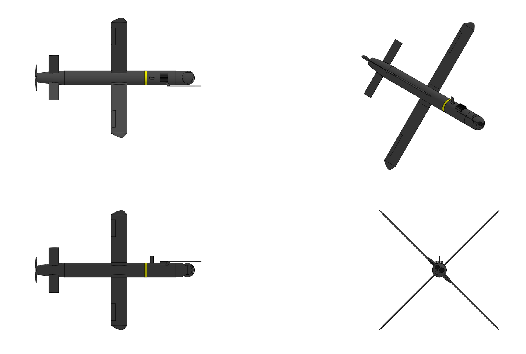
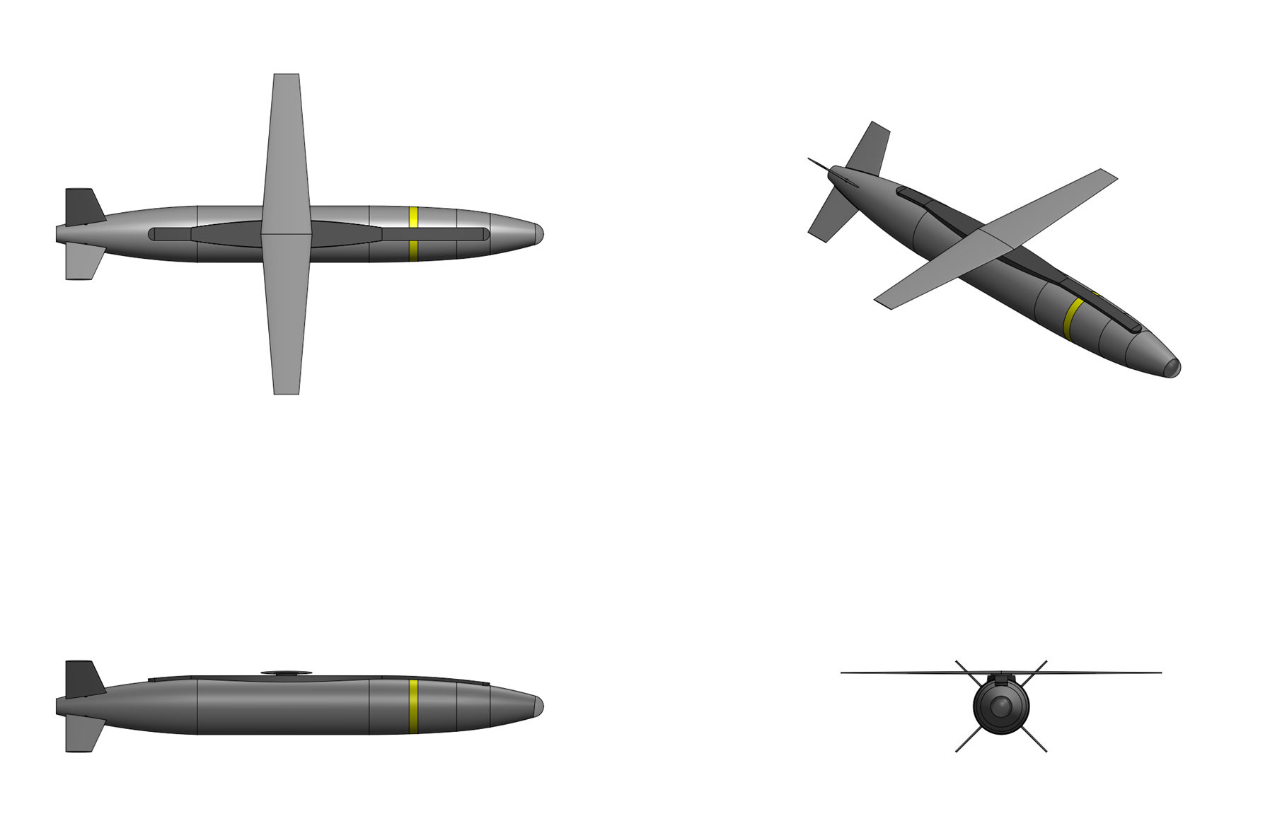
Sparrowhawk 200


General Characteristics:
Type:
Anti-armor loitering munition

Launch platform:
Portable launch tube

Guidance:
IR/EO, INS/GPS

Physical Characteristics:
Weight:
12 kg (munition), 18.0 kg (with launch tube)

Length:
1.3 m

Diameter:
0.13 m

Warhead:
2.5 kg tandem shaped charge

Performance Characteristics:
Propulsion:
Electric motor

Maximum speed:
100 knots

Cruise speed:
60 knots

Range:
40 km w/ 20 minute loiter

Endurance:
60 minutes


Overview:
The SDI Sparrowhawk 200 is a tube launched, fully autonomous loitering munition with an anti-armor warhead designed by SDI Missiles & Fire Control System designed for employment against armored targets in GPS-denied, communications-degraded, and electronically contested environments. Unlike operator-in-the-loop systems Sparrowhawk family of munitions are designed to operate with full onboard autonomy from launch to terminal engagement, requiring no sustained datalink or human piloting after deployment. The Sparrowhawk 200 is packaged inside of a man portable self-contained launch tube assembly (LTA) which contains the munition and a pneumatic ejection system which deploys the munition from the tube. The Sparrowhawk 200 munition itself possesses up to 60 minutes of flight endurance using an electric propulsion system with a low infrared and aural signatures and carries a multi-spectral electro-optical targeting sensor suite along with a shaped charge warhead with a fragmenting steel liner designed to be effective against both armored and unarmored vehicles, personnel, and materiel targets. The complete Sparrowhawk 200 munition system consists of a case containing twin launch tube assemblies and another case containing a touchscreen tablet based fire control unit (FCU) and a portable omni-directional datalink antenna system.


Airframe & Propulsion:
The Sparrowhawk 200 munition features a cylindrical fuselage 13 centimeters in diameter and 130 centimeters long constructed from wound graphite/epoxy composite. The rear of the munition contains the propulsion section with an brushless permanent-magnet electric motor driving a two bladed pusher propeller with a design cruise speed of 60 knots (110 km/h) and a maximum terminal dive speed of 100 knots (185 km/h). The electric motor is supplied electricity by a high power density thermal battery located inside the missile's midsection which gives the munition a flight time of up to 1 hour. Lift is provided by a flip-out cruciform wing mounted to the midsection of the missile which spring out after the munition is ejected from the launch tube assembly. Steering is provided by four rear flip-out tailfins actuated using an electro-mechanical control actuation system (CAS) powered by the missile's battery. The nose of the munition contains the terminal seeker with a dual-sensor 2-axis stabilized gimbal along with the missile's inertial measurement unit, GPS receiver, and digital autopilot system. The missile's shaped-charge warhead employs a main charge with a steel fragmentation liner which is located behind the battery.


Guidance:
The Sparrowhawk 200 is equipped with a 2-axis stabilized gimballed electro-optical sensor suite with two sensors; a 1280 x 720 pixel pixel color CCD imager with variable 46.8° – 1.2° field of view and up to 40x electronic zoom, and an uncooled 640 x 512 pixel LWIR (long-wave infrared) imager with variable 24.1° - 3.7° FOV and up to 6x electronic zoom. The sensor head features +30° to -90° tilt capability and capable of rotating a full 360° with 2-axis active stabilization and 6-axis vibration isolation from the missile body. Midcourse guidance capability is provided by a 6-axis strapdown inertial measurement unit (IMU) containing a 3-axis fiber optic gyro assembly and 3-axis MEMS (Micro Electro Mechanical System) silicon accelerometer which is coupled to a GPS unit with a 24 channel SAASM (Selective Availability Anti-spoofing Module) based anti-jam GPS receiver. The munitions' onboard GPS-aided INS is co-located with the twin cameras and allows the gimbal to be used to provide real-time geopointing and geolocation for targeting. Advanced embedded video processing features include AI enabled scene and target tracking tracking using SDI's "Sentient" AI-powered object detection and tracking software which runs on a ruggedized, low-power edge AI processor. Sentient runs on an embedded SDI Lattice GPGPU AI supercomputer, a low SWaP (Size, Weight, and Power) AI edge computing module with 275 TOPS of INT8 performance and 64GB of LPDDR5X memory. Sentient is designed to detects and identify targets and other objects of interest in the the sensor feed using machine learning algorithms trained on a library of multispectral data for both search characteristics and feature extraction and detects both stationary and moving objects including vehicles, people, and weapon systems in complex terrain and environments. Sentient is capable of detecting objects as small as 2x2 pixels with persistent tracking functionality that separate tracks for each detected object even when they overlap or pass behind temporary obstructions. For terminal homing Sentient supports closed loop, perception driven automatic target recognition (ATR) capability and autonomy homing with advanced search, 3D aimpoint selection, and terrain aware operations. Sentient's pixel lock targeting capability enables precise, persistent reidentification tracking of detected targets through signal degradation or loss when executing fully autonomous missions. The sensor suite of the munitions also employs SDI's HydraNav optical-navigation system for GPS-independent midcourse guidance. HydraNav combines the munition's electro-optical sensor with SDI's HydraVision real-time 3D mapping software and computes both absolute and relative navigation position updates through the fusion of three different HydraVision algorithms: a Stereo Terrain Correlation algorithm which captures overlapping images along the missile's flight path using the onboard FLIR and then correlates the real-time generated stereo elevation model with stored terrain references for precise geo-location determination, an Image-Based Feature Matching algorithm which matches image features in captured imagery with stored terrain image references, providing additional navigation location, and a Feature-Based Velocity Estimation algorithm which tracks image features from frame to frame to constrain inertial navigation system drift between HydraNav position updates.

Following launch the Sparrowhawk is designed to navigate towards the target area using a combination of INS/GPS and the munition's HydraNav terrain reference navigation system. Upon entering the designated target search area (defined by the operator at launch as a geographic polygon), the Sparrowhawk munition autonomously executes an optimized search pattern, a modified expanding-square or sector scan adapted in real-time based on terrain and assessed threat detection probability. The Sentient AI then continuously processes sensor data to detect, classify, and prioritize potential targets. Sentient's deep convolutional neural network (CNN) trained on military vehicle and equipment datasets then performs target classification, the model is designed to distinguish between vehicle classes such as main battle tanks, infantry fighting vehicles, self-propelled artillery, air defense systems, logistics vehicles, and static installations. Sentient's classifier then outputs a confidence score and a target-type label for each detected target. Sentient's onboard decision engine then evaluates detected targets against a pre-loaded engagement rule set defined by the operator before launch which specifies authorized target categories, geographic boundaries (no-engage zones), and minimum classification confidence thresholds. Once a suitable target has been selected the munition will then commit to a terminal attack dive if all engagement rule-set conditions are satisfied. Once committed, the munition then enters a steep terminal dive, switching to a high-refresh-rate tracking mode using fused IR/EO imagery where an aim-point selection algorithm identifies the most vulnerable point on the target to maximize warhead damage. The control system then guides the munition to impact, switching from bank-to-turn control to skid-to-turn control to increase the munition's terminal maneuverability. Precision terminal accuracy keeps collateral damage to a minimum (less than 1 CEP). If the munition fails to acquire a target it will automatically self-destructs if it fails to locate a target within its designated engagement area or if it passes through its predefined "kill box" without acquiring a valid target.

Although designed to operate primarily autonomously the Sparrowhawk can also be manually controlled in first-person view (FPV) mode using a 2-way datalink system which connects the munition to the touchscreen tablet based fire control unit (FCU). In first-person view (FPV) mode imagery from the sensor suite is transmitted using an L band (1,625MHz to 1,725 MHz) encrypted data link system at up to 4.5 Mbps to the system's tablet based fire control unit (FCU) through a portable data link antenna connected to the tablet. In FPV mode the munition's AI software runs in the background, highlighting objects of interest in the sensor scene which are surrounded by a color coded box which includes the detected target probable identification with a real time updating confidence interval assessment. The datalink system also allows for mid-mission attack adjustment when the munition is used autonomously, including options to adjust or change target search areas, change target priorities, or abort the attack and safely disarm and crash the munition. A low-bandwidth telemetry link also provide periodic status updates (munition position, battery state, search status) to the operator..


Warhead & Fuzing:
The Sparrowhawk 200 munition is equipped with a 2.5 kilogram shaped-charge (HEAT) warhead combing blast-fragmentation and shaped-charge effects which is effective against both armored and unarmored targets. The warhead is 12.4 centimeters in diameter and 13 centimeters long and consists of a high-fragmenting steel case containing a molybdenum shaped charge liner liner, 1.1 kilograms of polymer bonded HMX explosive (95.5% HMX, 4.5% Estane and 5702-Fl plastic binder), a syntactic foam wave-shaper, central and peripheral detonators, and an electro-mechanical safe & arm device (ESAD). When used against armored vehicles the warhead is detonated using nose mounted impact switch which triggers the the peripheral detonators in order to create a high speed, small diameter penetrating jet capable of penetrating in excess of 900 mm RHA after ERA. For attacking unarmored or lightly armored targets targets a height-of-burst proximity sensor in the nose of the munition is used to initiate the central and peripheral detonators which causes the main warhead's molybdenum shaped charge liner and high-fragmentation steel case to break up and release over 4,500 high-velocity fragments, creating a lethal-zone to exposed personnel over 10 meters in diameter.
Last edited by The Technocratic Syndicalists on Wed Apr 08, 2026 6:57 am, edited 10 times in total.
SDI AG
Arcaenian Military Factbook
Task Force Atlas
International Freedom Coalition


OOC: Call me Techno for Short
IC: The Kingdom of Arcaenia

User avatar
The Technocratic Syndicalists
Minister
 
Posts: 2349
Founded: May 27, 2015
Inoffensive Centrist Democracy

Postby The Technocratic Syndicalists » Sun Nov 29, 2020 5:13 pm

Image


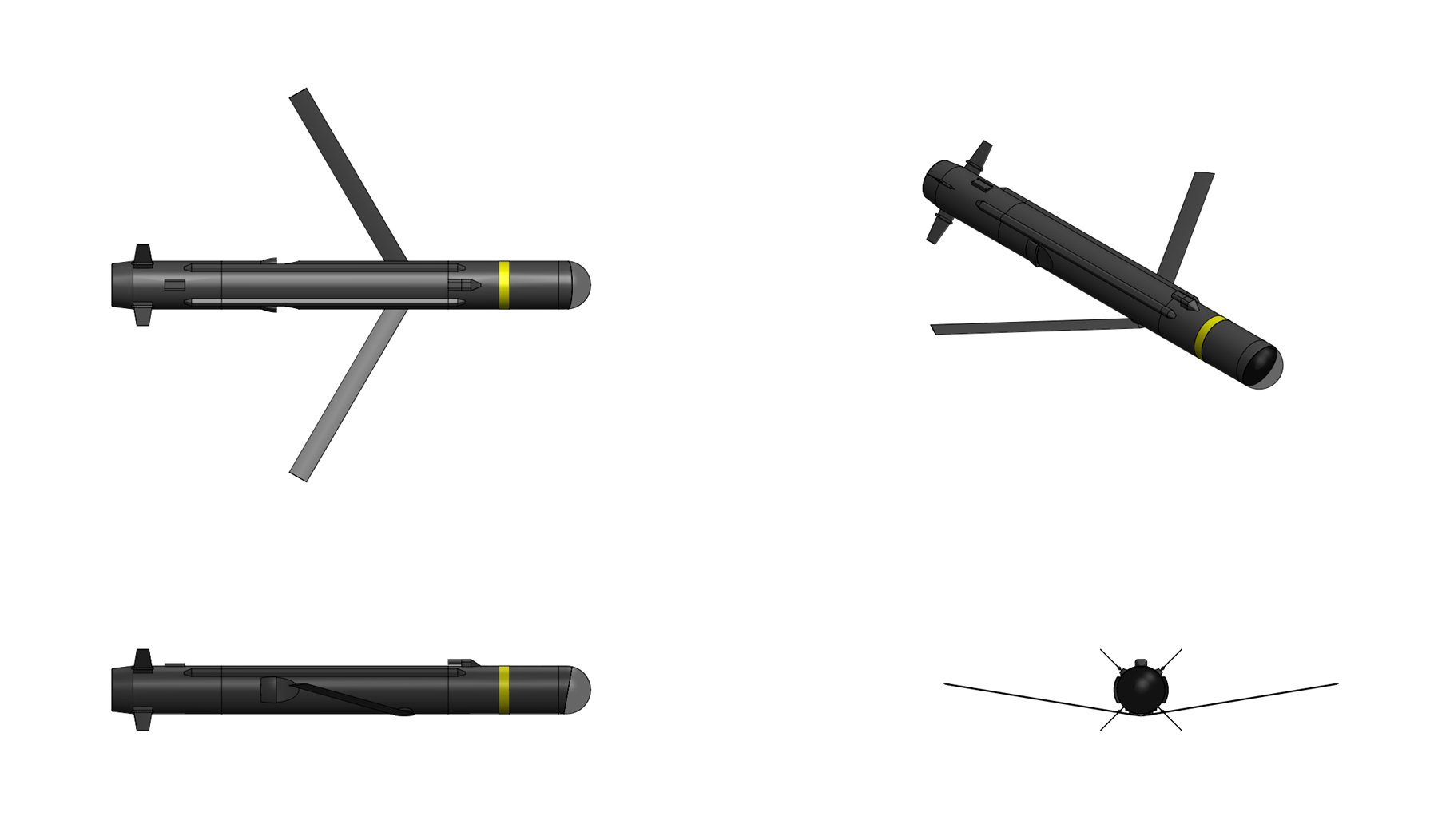
Sparrowhawk-400


General Characteristics:
Type:
Anti-armor loitering munition

Launch platform:
Vehicle, ship, helicopter

Guidance:
IR/EO, INS/GPS

Physical Characteristics:
Weight:
40.0 kg

Length:
2.0 m

Wingspan:
2.4 m

Diameter:
0.18 m

Warhead:
10.0 kg blast-fragmentation

Performance Characteristics:
Propulsion:
Electric motor

Maximum speed:
100 knots

Cruise speed:
60 knots

Range:
150 km

Endurance:
2 hours


Overview:
The SDI Sparrowhawk 400 is a fully autonomous, long-rang loitering munition designed by SDI Missiles & Fire Control System designed for employment against targets in GPS-denied, communications-degraded, and electronically contested environments. Unlike operator-in-the-loop systems Sparrowhawk family of munitions are designed to operate with full onboard autonomy from launch to terminal engagement, requiring no sustained datalink or human piloting after deployment. The Sparrowhawk 400 is designed to be launched from single or multi-canister launch systems which can be mounted on vehicles, naval vessels, or aircraft. The Sparrowhawk 400 munition itself possesses up to 120 minutes of flight endurance using an electric propulsion system with a low infrared and aural signatures and carries a multi-spectral electro-optical targeting sensor suite along with a blast-fragmentation warhead designed to be effective against both armored and unarmored vehicles and materiel targets. .


Airframe & Propulsion:
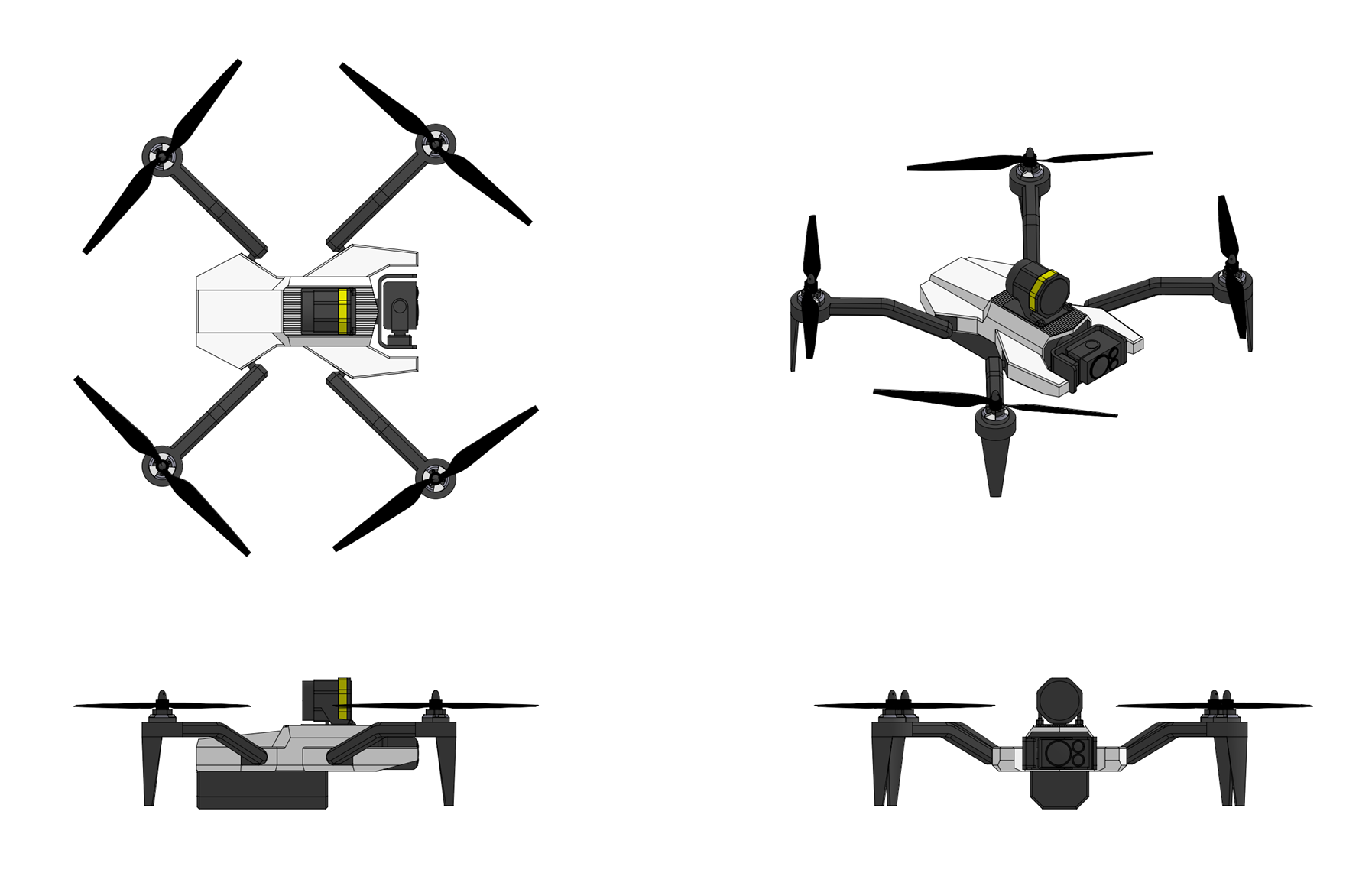
The Sparrowhawk 400 munition features a cylindrical fuselage 18 centimeters in diameter and 200 centimeters long constructed from wound graphite/epoxy composite. The rear of the munition contains the propulsion section with an brushless permanent-magnet electric motor driving a two bladed pusher propeller with a design cruise speed of 60 knots (110 km/h) and a maximum terminal dive speed of 100 knots (185 km/h). The electric motor is supplied electricity by a high power density thermal battery located inside the missile's midsection which gives the munition a flight time of up to 2 hours. Lift is provided by a flip-out cruciform wing mounted to the midsection of the missile which spring out after the munition is ejected from the launch tube assembly. Steering is provided by four rear flip-out tailfins actuated using an electro-mechanical control actuation system (CAS) powered by the missile's battery. The nose of the munition contains the terminal seeker with a tri-sensor 2-axis stabilized gimbal along with the missile's inertial measurement unit, GPS receiver, and digital autopilot system. The missile's sblast-fragmentation warhead consists of a hardened steel case with an explosive fill and is located ahead of the the battery module.


Guidance:
The Sparrowhawk 400 is equipped with a 2-axis stabilized gimballed electro-optical sensor suite with three sensors; a 1280 x 720 pixel pixel color CCD imager with continuously variable 16.9° - 0.6° FOV and up to 30x electronic zoom, a cooled 1280 x 1024 pixel MWIR (mid-wave infrared) imager with continuously variable 18.2° - 1.4° FOV and up to 10x electronic zoom, and a 640x480 pixel SWIR (short-wave infrared) imager variable 5.7° - 2.9° FOV with 2x electronic zoom. The sensor head features +30° to -90° tilt capability and capable of rotating a full 360° with 2-axis active stabilization and 6-axis vibration isolation from the missile body. Midcourse guidance capability is provided by a 6-axis strapdown inertial measurement unit (IMU) containing a 3-axis fiber optic gyro assembly and 3-axis MEMS (Micro Electro Mechanical System) silicon accelerometer which is coupled to a GPS unit with a 24 channel SAASM (Selective Availability Anti-spoofing Module) based anti-jam GPS receiver. The munitions' onboard GPS-aided INS is co-located with the twin cameras and allows the gimbal to be used to provide real-time geopointing and geolocation for targeting. Advanced embedded video processing features include AI enabled scene and target tracking tracking using SDI's "Sentient" AI-powered object detection and tracking software which runs on a ruggedized, low-power edge AI processor. Sentient runs on an embedded SDI Lattice GPGPU AI supercomputer, a low SWaP (Size, Weight, and Power) AI edge computing module with 275 TOPS of INT8 performance and 64GB of LPDDR5X memory. Sentient is designed to detects and identify targets and other objects of interest in the the sensor feed using machine learning algorithms trained on a library of multispectral data for both search characteristics and feature extraction and detects both stationary and moving objects including vehicles, people, and weapon systems in complex terrain and environments. Sentient is capable of detecting objects as small as 2x2 pixels with persistent tracking functionality that separate tracks for each detected object even when they overlap or pass behind temporary obstructions. The sensor suite of the munitions also employs SDI's HydraNav optical-navigation system for GPS-independent midcourse guidance. HydraNav combines the munition's electro-optical sensor with SDI's HydraVision real-time 3D mapping software and computes both absolute and relative navigation position updates through the fusion of three different HydraVision algorithms: a Stereo Terrain Correlation algorithm which captures overlapping images along the missile's flight path using the onboard FLIR and then correlates the real-time generated stereo elevation model with stored terrain references for precise geo-location determination, an Image-Based Feature Matching algorithm which matches image features in captured imagery with stored terrain image references, providing additional navigation location, and a Feature-Based Velocity Estimation algorithm which tracks image features from frame to frame to constrain inertial navigation system drift between HydraNav position updates.

Following launch the Sparrowhawk is designed to navigate towards the target area using a combination of INS/GPS and the munition's HydraNav terrain reference navigation system. Upon entering the designated target search area (defined by the operator at launch as a geographic polygon), the Sparrowhawk munition autonomously executes an optimized search pattern, a modified expanding-square or sector scan adapted in real-time based on terrain and assessed threat detection probability. The Sentient AI then continuously processes sensor data to detect, classify, and prioritize potential targets. Sentient's deep convolutional neural network (CNN) trained on military vehicle and equipment datasets then performs target classification, the model is designed to distinguish between vehicle classes such as main battle tanks, infantry fighting vehicles, self-propelled artillery, air defense systems, logistics vehicles, and static installations. Sentient's classifier then outputs a confidence score and a target-type label for each detected target. Sentient's onboard decision engine then evaluates detected targets against a pre-loaded engagement rule set defined by the operator before launch which specifies authorized target categories, geographic boundaries (no-engage zones), and minimum classification confidence thresholds. Once a suitable target has been selected the munition will then commit to a terminal attack dive if all engagement rule-set conditions are satisfied. Once committed, the munition then enters a steep terminal dive, switching to a high-refresh-rate tracking mode using fused IR/EO imagery where an aim-point selection algorithm identifies the most vulnerable point on the target to maximize warhead damage. The control system then guides the munition to impact, switching from bank-to-turn control to skid-to-turn control to increase the munition's terminal maneuverability. Precision terminal accuracy keeps collateral damage to a minimum (less than 1 CEP). If the munition fails to acquire a target it will automatically self-destructs if it fails to locate a target within its designated engagement area or if it passes through its predefined "kill box" without acquiring a valid target.

Although designed to operate primarily autonomously the Sparrowhawk can also be manually controlled in first-person view (FPV) mode using a 2-way datalink system which connects the munition to the touchscreen tablet based fire control unit (FCU). In first-person view (FPV) mode imagery from the sensor suite is transmitted using an L band (1,625MHz to 1,725 MHz) encrypted data link system at up to 4.5 Mbps to the system's tablet based fire control unit (FCU) through a portable data link antenna connected to the tablet. In FPV mode the munition's AI software runs in the background, highlighting objects of interest in the sensor scene which are surrounded by a color coded box which includes the detected target probable identification with a real time updating confidence interval assessment. The datalink system also allows for mid-mission attack adjustment when the munition is used autonomously, including options to adjust or change target search areas, change target priorities, or abort the attack and safely disarm and crash the munition. A low-bandwidth telemetry link also provide periodic status updates (munition position, battery state, search status) to the operator..


Warhead & Fuzing:
The Sparrowhawk 400 munition is equipped with a 10 kilogram penetrating blast-fragmentation warhead intended for engaging soft to semi-hardened targets including buildings, bunkers, small boats, and light armored vehicles. The warhead consists of a hardened steel case filled with 2.5 kilograms of insensitive polymer bonded explosive (65% HMX, 30% aluminum, 5% Hytemp and DOA binder), twin zirconium sponge incendiary charges, and an aft fuzewell. The twin zirconium sponge incendiary charges add an incendiary effect to the warhead for enhanced effectiveness against materiel targets and consists of two 110 gram cylinders made from sifted zirconium metal particles pressed together with calcium stearate flakes. The two incendiary cylinders are bolted with a stainless steel bolt to the front inside of the steel case, the steel warhead casing with incendiary cylinders installed being coated internally with Polyethylene before the PBX explosive charge cast is pressed into the case over the incendiary cylinders and the slotted base plate with fuze well and Time Delay Fuze Assembly (TDFA) is then screwed onto the aft end of the warhead case. The warhead function sequence is initiated when either crush switch located in the forward guidance section is closed, where the the time delay circuit in the TDFA either detonates the warhead immediately provides a delay to allow time for the blast-frag warhead to pass through a barrier before providing a detonation output to the blast-frag warhead. The warhead can also be detonated in an airburst mode using a laser height-of-burst sensor built into the munition's forward guidance section. Upon detonation the the damage mechanism of the warhead consists of blast energy from the warhead explosive fill coupled with initiation of incendiary cylinders in the front of the warhead and steel case fragmentation.
Last edited by The Technocratic Syndicalists on Sun Apr 12, 2026 9:42 am, edited 18 times in total.
SDI AG
Arcaenian Military Factbook
Task Force Atlas
International Freedom Coalition


OOC: Call me Techno for Short
IC: The Kingdom of Arcaenia

User avatar
The Technocratic Syndicalists
Minister
 
Posts: 2349
Founded: May 27, 2015
Inoffensive Centrist Democracy

Postby The Technocratic Syndicalists » Mon Feb 07, 2022 8:43 pm

Image


RBS 99 Bolide


General Characteristics:
Type:
Tactical ballistic missile

Launch platform:
TEL

Guidance:
Synthetic-aperture radar (SAR), INS/GPS, 2-way RF datalink

Physical Characteristics:
Weight:
4,800 kg

Length:
8.1 m

Diameter:
1.0 m

Warhead:
    Rb 99A:
    24x terminally guided submunitions (TGSM)

    Rb 99B:
    500 kg unitary penetrator

Performance Characteristics:
Propulsion:
Solid fuel rocket

Speed:
Mach 9 (2,700 m/s) burnout

CEP:
<1 m (<3m with GPS/INS only)

Flight ceiling:
200 km

Range:
100 to 800 km


Overview:
The RBS 99 Bolide is a mobile ballistic missile system designed by SDI Missile Systems designed to engage high value tactical and strategic targets deep in enemy territory. The RBS 99 is intended to be used with the A 13 Vanguard battlefield surveillance aircraft to form part of a reconnaissance-strike system for attacking massed armor formations and mobile surface-to-surface and surface-to-air units deep behind enemy lines. The RBS 99 comes in two variants, the RBS 99A which carries a payload of terminally guided anti-armor submunition payload for attacking armored formations, mobile surface to surface missile launchers and mobile air and missile defense systems, the RBS 99B whic carries a unitary penetrator intended for attacking warships, structures, infrastructure targets, and hardened and deeply buried targets. Both variants share the same basic propulsion section with a detachable maneuvering reentry vehicle (MaRV) section interchangeable between all three variants, allowing missiles to be rapidly reconfigured with a different warhead in the field. When combined with target designation capability from the A 13 Vanguard battlefield surveillance aircraft the RBS 99 forms part of a reconnaissance-strike system for attacking massed armor formations, mobile surface-to-surface and surface-to-air units, and other mobile and relocatable targets deep behind enemy lines.

The components of the RBS 99 system include the Rb 99 missile, transporter-erector-launcher vehicle (SDI HTTS chassis) with two missiles, transporter and loader vehicle (SDI HTTS chassis) with two reloads each and a 30 kW generator and hydraulic crane, command vehicle, (GdW 30 chassis), mobile communication center vehicle, (GdW 30 chassis), and mobile workshop vehicle (SDI HTTS chassis). A complete RBS 81 battery consists of eight transporter-erector-launcher vehicles, eight transporter and loader vehicles, two firing platoon command vehicles, one battery command vehicle, one mobile communication center vehicle, and one mobile workshop vehicle.


Airframe & Propulsion:
The Rb 99 missile consists of four sections: a propulsion section and a nd a maneuvering reentry vehicle (MARV) section. The maneuvering reentry vehicle (MARV) is further divided into a guidance and control/adapter (G&C/A) section, warhead section, and radar section. The propulsion section consist of a solid rocket motor with forward and aft skirts, the forward skirt mating to the reentry vehicle. The propulsion section contains 3,600 kilograms of high energy density composite solid propellant with a 90% solid loading consisting of 20% aluminum fuel, 24% HMX, 46% AP oxidizer, and 10% HTPB and burns for 60 seconds with a peak thrust of 170 kN and a sea level specific impulse of 280 seconds, accelerating the missile to a burnout velocity of around mach 9 (2,700 m/s). The forward skirt contains three thrust termination ports spaced evenly around the motor casing which are activated by the missile's guidance and control computer after reentry vehicle separation, proving a reverse thrust in the propulsions section to allow the reentry vehicle to cleanly separate from the propulsion section. The aft skirt contains four control fins, two fixed fins and two hydraulically actuated fins to provide first stage roll control, and a gimballed nozzle with two hydraulic actuators which provides pitch and yaw control. The motor case is made from graphite/epoxy composite with the motor nozzle constructed from triaxially braided 3-D carbon-carbon composite. Both forward and aft skirts are made from 7075 aluminum alloy.

The missiles' maneuvering reentry vehicle consists of an adaptor, guidance and control section, warhead section, and radar section. The adaptor section connects the reentry vehicle to the propulsion section and consists of conical 7075 aluminum alloy structure with a heat-resistant phenolic coating. The guidance and control section contains the missile's guidance electronics unit (GEU), control fins system, missile thermal battery, reaction control system, and reentry vehicle separation system. The guidance electronics unit controls all functions of the missile during flight and contains the missile's flight computer, synthetic aperture radar (SAR) processor, datalink transceiver unit, 6-axis ring laser gyro (RLG) inertial measurement unit (IMU), and 24 channel dual-frequency Selective Availability Anti-spoofing Module (SAASM) based GPS receiver. The control fin system consists of four hydraulically actuated control fins which provide reentry vehicle control during the terminal stage of flight. The reaction control system consists of a total of 10 warm-gas attitude-control thrusters placed behind the control fins which provide reentry vehicle roll, pitch, and yaw control during the exo-atmospheric midcourse phase of flight. Behind the reaction control system at the aft end of the reentry vehicle is the separation system which contains a linear shaped charge (LSC) ring assembly which separates the reentry vehicle from the adaptor section on the command of the missile's flight computer. Forward of the guidance and control section is the warhead section which contains cables that connect the G&C section to radar section and depending on the missile variant contains either a cluster munition payload or a unitary penetrator warhead. Forward of the warhead section is the radar section which contains a pair of wideband conformal datalink antennas along with the missile's synthetic aperture radar antenna unit which is enclosed in a high temperature reaction-sintered silicon nitride (Si3N4) radome.


Guidance & Flight Sequence:
The Rb 99 missile is guided by a terminal linear frequency modulated - continuous wave (LFM-CW) synthetic aperture radar (SAR) seeker coupled with an INS/GPS midcourse guidance unit and a two-way datalink which allows the missile to be retargeted in flight by an A 13 Aircraft. The synthetic aperture radar (SAR) seeker is contained inside a radome in the radar section of the reentry vehicle and consists of a stabilized antenna unit with a 17 cm diameter antenna operating in the X-band (9.3–9.6 GHz). The antenna is coupled with a strapdown 6-axis laser-ring gyro based IMU to compensate for motion by the reentry vehicle during seeker operation. Guidance during the boost and midcourse phases of flight is provided a 6-axis ring laser gyro (RLG) based inertial measurement unit (IMU) and a 24 channel dual-frequency (L1/L2) SAASM (Selective Availability Anti-spoofing Module) based GPS receiver contained in the missile's guidance electronics unit section which provides accurate all-weather midcourse guidance for the missile. In case of synthetic aperture radar (SAR) seeker failure the INS/GPS guidance system can also be used for terminal guidance against stationary geolocated targets or a combination of INS/GPS and external command guidance by an A 13 Aircraft against mobile targets with a slight reduction in accuracy.

After ignition the missile's inertial measurement unit is used to maneuver it onto a precomputed firing azimuth with missile pitch and yaw control provided by the gimballed thrust-vector control (TVC) nozzle and roll control provided by the propulsion section aft control fins. The propulsion section motor then burns until the desired burn out velocity is achieved where the reentry vehicle separation system and thrust reversal systems are activated, separating the reentry vehicle from the propulsion section. Following separation from the propulsion section the reaction control thrusters in the reentry vehicle are used to maintain attitude control and orient the reentry vehicle for atmospheric reentry. During the phase the reentry vehicle can also receive guidance updates from an A 13 Aircraft using the wideband conformal datalink antennas on the reentry vehicle, allowing the missile to be retargeted in flight. When the reentry vehicle enters the denser part of the atmosphere the control fins are used for control where at an altitude of around 30 kilometers the reentry preforms a high-g pull-up maneuver, glides to the target area, and then over the target performs a pull-down mabuever and dives down on the target at a near vertical area. During the final dive down onto the target the synthetic aperture radar (SAR) seeker in the nose of the reentry vehicle is activated and performs a <1 meter resolution 5 x 5 kilometer squint mode stripmap scan of the terrain under the path of the reentry vehicle. The synthetic aperture radar (SAR) processor in the missile's guidance electronics unit (GEU) then compares the scene generated by the seeker to a target reference template stored in the computers memory to identify the location of the target within the scene. When the target has been detected and located in the scene the guidance computer then computes the necessary trajectory corrections to impact the target and applies them using the control fins on the reentry vehicle. Should the seeker malfunction or fail to squire the target the missile can also be command guided in the terminal phase by an A 13 Aircraft using its FMG 110 radar to track both the missile and intended target and continually transmit guidance updates to the missile through its datalink system.


Warhead
Rb 99A: The Rb 99A is designed primarily to attack columns of armored vehicles, MLRS units, surface to air and surface to surface missile systems and contains a payload of 24 terminally guided submunitions (TGSMs). The submunitions are contained in two radial rows, one of 16 submunitions and one of 8 submunitions, surrounding a central air bag dispenser system mounted to central structural tunnel which connects the radar and guidance and control sections of the reentry vehicle. At an altitude of around 1,000 meters the missile's flight computer detonates a pair of of linear shaped charges running along the sides of the warhead section which cut open the aluminum skin panels of the warhead section where the airbags are then activated, expelling the submunitions from the reentry vehicle in two concentric rows. Each TGSM is 140 mm in diameter and 900 mm long with a weight of 20.0 kiligrams and consists of a front seeker section with gimballed 2-axis stabilized dual-mode 94 Ghz millimetric wave (MMW) radar and 128 x 128 pixel LWIR (8 – 12 µm) imaging infrared (IIR) seeker and impact fuze, guidance electronics section with inertial measurement unit (IMU), control electronics unit, and precursor warhead, warhead section with electro-mechanical safe & arm device (ESAD) and main shaped charge warhead, and rear tail control unit with thermal battery, air data sensor, deployable tail steering fins and electro-mechanical control actuation system. The TGSM employs a shaped charge warhead with a forward precursor warhead employing a two-layered molybdenum liner designed to defeat explosive reactor armor (ERA) and a main shaped charge warhead employing a copper liner and capable of penetrating over 1,100 mm of RHA. After being deployed from the missile each TGSM deploys its four rear rear tailfins to stabilize itself and then deploys a set of midbody fabric wings and performs a pull-up maneuver and enters a constant altitude glide towards the target area. While gliding towards the target area each TGSM scans back and forth across a ground track 1 to 2 kilometers wide with its radar seeker and uses high range resolution (HRR) radar processing and high resolution SAR mapping to detect and image both moving and stationary targets. When the seeker's automatic target recognition (ATR) algorithms identify a tank or other armored target the submunition steers towards the target and then descends in a terminal dive, impacting the top of the target where its shaped charge warhead detonates on impact.

Rb 99B: The Rb 99B replaces the cluster munition dispenser warhead of the A variant with a 500 kilogram penetrating blast-fragmentation warhead which is intended for attacking hardened and deeply buried targets The warhead consists of a streamlined steel case 2.4 meters long and 37 centimeters in diameter constructed from 3.5 GPA (500,000 psi) tensile strength nickel-molybdenum-cobalt maraging steel (8Ni-14Mo-20Co-Fe) filled with 125 kilograms of insensitive enhanced blast explosive (50% HMX, 30% Al powder, 20% PCP/TMETN energetic binder/plasticizer). The warhead is fitted with a base mounted hard target smart fuze containing a precision MEMS accelerometer and micro-controller which features void sensing, layer counting, depth of penetration, and time time delay after impact fuzing modes. The detonator is entirely electronic with no moving parts and uses an exploding foil initiator (EFI) detonator to initiate the main explosive charge which is armed in flight and requires a constant 500 V from the missile's power system to function. When used against hard and deeply buried targets the high supersonic impact velocity of the missile allows the warhead to penetrate over 7 meters of 34.5 MPa reinforced concrete before exploding.
Last edited by The Technocratic Syndicalists on Sun Oct 26, 2025 6:45 pm, edited 5 times in total.
SDI AG
Arcaenian Military Factbook
Task Force Atlas
International Freedom Coalition


OOC: Call me Techno for Short
IC: The Kingdom of Arcaenia

User avatar
The Technocratic Syndicalists
Minister
 
Posts: 2349
Founded: May 27, 2015
Inoffensive Centrist Democracy

Postby The Technocratic Syndicalists » Tue May 10, 2022 7:55 pm

Image


RBS 310


General Characteristics:
Type:
Hypersonic boost-glide missile

Launch platform:
TEL

Guidance:
INS/GPS

Physical Characteristics:
Weight:
3,800 kg

Length:
8.2 m

Diameter:
0.8 m

Warhead:
6x terminally guided submunitions (TGSM)


Performance Characteristics:
Propulsion:
two-stage solid fuel rocket

Speed:
Mach 10 (3,000 m/s) burnout

CEP:
3 m

Flight ceiling:
35 km

Range:
2,000 km


Overview:
The RBS 310 is a hypersonic boost-glide missile system designed by SDI Missile Systems designed to engage high value tactical and strategic targets deep in enemy territory. The missile consists of a two-stage solid fuel rocket booster attached to a maneuvering hypersonic glide vehicle which carries a payload of terminally guided submunitions attacking mobile surface to surface missile launchers and mobile air and missile defense systems


Airframe & Propulsion:
The RBS 310 missile consists of five sections, a first stage propulsion section, second stage propulsion section, adapter, hypersonic glide vehicle (HGV), and ejectable nosecone . The first stage propulsion section of the missile consists of a solid fuel rocket motor with attached forward and aft skirts skirt. The forward skirt mates to the to the second stage propulsion system while the aft skirt contains four movable control fins and a gimballed thrust vector control (TVC) nozzle with two electrohydraulic actuator which provides pitch and yaw control during first stage burn. The first stage motor is constructed from transverse wound carbon-fiber-reinforced polyetheretherketone (PEEK) with an internal aramid-filled ethylene propylene diene monomer (EPDM) insulation liner and contains contains 1,800 kilograms of high energy density composite solid propellant with a 90% solid loading consisting of 20% aluminum fuel, 24% HMX, 46% AP oxidizer, and 10% HTPB binder. The first stage burns or 30 seconds and accelerates the missile to a nominal burnout velocity of 1.5 km/s.

The second stage propulsion section features a variable burn time and accelerates the missiles to the required burnout velocity computed by the guidance system as a function of target range and planned trajectory. The first stage the second stage consists of a solid propellant rocket motor with forward and aft skirts. The forward skirt of the second stage contains contains three thrust termination ports spaced evenly around the forward motor casing which are activated by the missile's guidance computer after the desired burnout velocity has been reached, extinguishing the second stage motor and proving a reverse thrust in the second stage motor which allow the glide vehicle to cleanly separate from the second stage. Like the first stage the aft skirt houses four movable control fins and a gimballed thrust vector control (TVC) nozzle with two electrohydraulic actuator which provides pitch and yaw control during first stage burn. The second stage is constructed from transverse wound carbon-fiber-reinforced polyetheretherketone (PEEK) with an internal aramid-filled ethylene propylene diene monomer (EPDM) insulation liner with an additional external sacrificial aramid fiber overwrap and contains 1,100 kilograms of 20% aluminum, 24% HMX, 46% AP, and 10% HTPB composite propellant. The second stage motor burns for a maximum of 30 seconds and accelerates the missiles to a maximum burnout velocity of 3.0 km/s at an altitude of 35,000 meters where the missile's hypersonic glide vehicle (HGV) separates from the second stage and begins its hypersonic glide towards the target

The missile's hypersonic glide vehicle (HGV) consists of a conical shaped vehicle with four rear mounted control fins which contains the missile's guidance and navigation system and submunition payload. The hypersonic glide vehicle is covered by a nose cone ejected following second stage burn which serves to protect the glide vehicle from environmental or mechanical damage during handling and loading. The structure of the glide vehicle is contracted from Ti-6Al-4V titanium alloy with a hafnium carbide (HfC) coated 3-D carbon/carbon phenolic heatshield with internal carbon foam insulation which is bonded to the underlying titanium glide vehicle structure with pyrolytic graphite supports. The four control fins are constructed from carbon fiber reinforced silicon carbide (C/SiC) and are actuated by a set of four electro-mechanical actuators inside the glide vehicle body to provide roll, pitch, and yaw control during flight. Behind the nose of the glide vehicle contains the missile's guidance and navigation section which contains the missile flight computer, twin 6-axis inertial measurement units (IMUs), and 24 channel dual-frequency Selective Availability Anti-spoofing Module (SAASM) based GPS receiver. Aft of the guidance section is the payload section which contains six submunitions inside launch canisters which are ejected from the aft of the glide vehicle in the terminal phase of flight.


Guidance & Flight Sequence:
The reentry vehicle is guided in flight through a combination GPS/INS system which combines twin inertial measurement units employing 3-axis laser-ring gyros (LRGs) and 3-axis pendulous integrating gyroscopic accelerometers which are coupled to a Selective Availability Anti-spoofing Module (SAASM) based GPS receiver with four dual frequency (L1/L2) conformal wideband GPS antenna blended into the rear surface of the glide vehicle. The INS/GPS guidance is coupled with the ability to employ external command guidance by an A 13 Aircraft against mobile targets employing a pair of 1-way datalink antennas blended into the aft end of the glide vehicle alongside the GPS antennas.

After ignition the missile's inertial measurement unit is used to maneuver it onto a precomputed firing azimuth with missile pitch and yaw control provided by the gimballed thrust-vector control (TVC) nozzle and roll control provided by the propulsion section aft control fins. Following first stage burnout the missile is then programmed to enter short coast period before the missile guidance computer issues the first stage separation signal. Following reception of the first stage separation command a linear shaped charge array in the aft skirt of the second stage is detonated, separating the second stage from the first stage. The second stage is then ignited, accelerating the missile along its intended flight path. When the guidance computer determines that the desired burnout velocity, altitude, and burnout angle have been reached the guidance computer issues a second stage separation signal which simulatrnosuly activates he thrust termination ports in the second stage motor and detonates a linear shaped charge array in the glide vehicle adapter section, separating the glide vehicle from the second stage.

On a maximum range trajectory the hypersonic glide vehicle is released from the second stage of the missile at a velocity of around 3.0 kilometers per second at an altitude of approximately 35,000 meters where the vehicle orients itself using it's INS and establishes an optimal angle of attack before beginning its hypersonic glide towards the intended target area. After gliding to the intended target area the glide vehicle performs a high-G pull-down maneuver from its final glide altitude of around 30,000 meters and dives down sharply towards its intended target area where the vehicle performs an aerobraking maneuver to decelerate to low supersonic speeds where the terminally guided submunition payload is then released.


Warhead
The Rb 310 is designed primarily to attack multiple rocket launcher, surface to air and surface to surface missile systems and contains a payload of six terminally guided submunitions (TGSMs). The submunitions are contained in a single radial rows of 6 submunition each contained in a pneumatic launch tube which ejects the submunition from the rear of the hypersonic glide vehicle at an altitude between 2,000 and 4,000 meters above ground level. Each TGSM is 140 mm in diameter and 900 mm long with a weight of 20.0 kilograms and consists of a front seeker section with gimballed 2-axis stabilized dual-mode 94 Ghz millimetric wave (MMW) radar and 128 x 128 pixel LWIR (8 – 12 µm) imaging infrared (IIR) seeker and impact fuze, guidance electronics section with inertial measurement unit (IMU), control electronics unit, and precursor warhead, warhead section with electro-mechanical safe & arm device (ESAD) and main shaped charge warhead, and rear tail control unit with thermal battery, air data sensor, deployable tail steering fins and electro-mechanical control actuation system. The TGSM employs a shaped charge warhead with a forward precursor warhead employing a two-layered molybdenum liner designed to defeat explosive reactor armor (ERA) and a main shaped charge warhead employing a copper liner and capable of penetrating over 1,000 mm of RHA. After being deployed from the missile each TGSM deploys its four rear rear tailfins to stabilize itself and then deploys a set of midbody fabric wings and performs a pull-up maneuver and enters a constant altitude glide towards the target area. While gliding towards the target area each TGSM scans back and forth across a ground track 1 to 2 kilometers wide with its radar seeker and uses high range resolution (HRR) radar processing and high resolution SAR mapping to detect and image both moving and stationary targets. When the seeker's automatic target recognition (ATR) algorithms identify a tank or other armored target the submunition steers towards the target and then descends in a terminal dive, impacting the top of the target where its shaped charge warhead detonates on impact.
Last edited by The Technocratic Syndicalists on Tue Mar 31, 2026 9:30 am, edited 13 times in total.
SDI AG
Arcaenian Military Factbook
Task Force Atlas
International Freedom Coalition


OOC: Call me Techno for Short
IC: The Kingdom of Arcaenia

User avatar
The Technocratic Syndicalists
Minister
 
Posts: 2349
Founded: May 27, 2015
Inoffensive Centrist Democracy

Postby The Technocratic Syndicalists » Tue Jun 14, 2022 5:29 pm

Image


Rb 81


General Characteristics:
Type:
Medium range surface-to-air missile

Launch platform:
TEL, VLS

Guidance:
Ka band active radar homing, INS/GPS, RF datalink

Physical Characteristics:
Weight:
320 kg

Length:
5.0 m

Diameter:
280 mm

Warhead:
25 kg blast/fragmentation

iPerformance Characteristics:
Propulsion:
Dual-pulse solid fuel rocket

Speed:
Mach 4.5

Maneuverability:
60 G

Operational range:
1-120 km

Intercept altitude:
0-25 km


Overview:
The Rb 81 is a medium range surface-to-air missile designed by SDI Missile Systems. The Rb 81 forms part of SDI's RBS 81 medium range air and missile defense system and combines a dual-mode terminal seeker integrating Ku-band active radar homing (ARH) and long-wave infrared (LWIR) imaging infrared (IIR) guidance, mid-course strapdown inertial navigation with C or X-band datalink updates from the launch platform’s fire control radar, a high-energy dual-pulse solid rocket motor achieving speeds in excess of Mach 4.5 with sustained Mach 4.0+ flight throughout the terminal engagement, a 60+ G maneuvering capability, and a 25 kg multi-mode blast/fragmentation warhead with selectable detonation modes and multimode proximity fuzing which provide engagement capability against a complete spectrum of modern aerial threats including fixed and rotary wing aircraft, anti-ship cruise missiles including supersonic sea-skimmers, tactical ballistic missiles, unmanned aerial systems of all groups, loitering munitions, and terminal hypersonic threats.


Airframe & Propulsion:
The Rb 81 missile consists of four sections including the seeker & guidance section, warhead section, rocket motor section, and rear control section. The seeker & guidance section houses the dual-mode Ku-band ARH and LWIR IIR focal plane array seekers, the seeker gimbal assembly, the guidance electronics module, and the RF/IR signal processors. The radome is a precision-machined silicon nitride ceramic composite structure. The guidance section contains the strapdown inertial measurement unit , the X/S-band datalink receiver/transmitter, the GPS anti-jam antenna and receiver (SAASM-compatible), the mission computer (a dual-core radiation-hardened processor), and the power distribution unit. The warhead section Houses the 25 kg multi-mode blast/fragmentation warhead with its dual-layer selectable fragmentation jacket, the insensitive high explosive main charge, the multimode fuzing system (radar proximity, laser proximity, and contact fuzes), the electronic safe-and-arm device, and the warhead mode selection electronics. The dual-pulse solid rocket motor section includes the forward grain, the inter-pulse insulation barrier, the aft grain, the common motor case, and the fixed convergent-divergent exhaust nozzle. The tail control section houses the missile's four tail control fins, tailfin actuators and TVC nozzle system. The four tail control fins are stowed flush against the body during canister storage and deploy within 50 milliseconds of launch via spring-loaded deployment with pyrotechnic release.

The 28 centimeter diameter dual-pulse rocket motor consists of two radial burning propellant grains separated by a flexible elastomeric bulkhead, a blast tube, and a nozzle. The motor features a 50/50 propellant split between the first and second pulses and employs SDI's minimum-smoke insensitive tactical propellant consisting of 25.5% GAP energetic binder, 4.5% TMETN (trimethylolethane trinitrate) plasticizer, 58.5% ADN (ammonium dinitramide) oxidizer, and 11.5% HMX (Octogen) combining high specific impulse and burn rate, low impact and thermal sensitivity, and low exhaust signature. The first pulse is a high-energy booster grain provides approximately 120 kN of thrust for 4.5 seconds, accelerating the missile to greater than Mach 4.5. After a programmed coast period determined by the fire control system based on the engagement geometry, the second pulse ignites and provides re-accelerates the missile, maintaining the missile above Mach 4.0 throughout the terminal engagement phase and providing the aerodynamic control authority necessary for 60+ G evasion-defeating maneuvers. The two grains are separated by an inter-pulse insulation barrier constructed from phenolic-impregnated carbon ablative (PICA) material bonded to both grain faces. The barrier is designed to withstand the thermal soak from the first pulse grain’s combustion products, after which the fire control system commands the second pulse ignition via an electronic safe-and-arm initiator embedded in the barrier. The variable coast period enables the fire control system to optimize the missile’s energy profile for each unique engagement geometry. For short range high-off boresight engagements an all-boost burn profile with no delay between pulses is used while for longer ranged engagements a lofted trajectory with a boost-coast-boost burn profile is used. The motor casing is constructed from filament-wound graphite reinforced polyetheretherketone (PEEK) with an internal aramid-filled ethylene propylene diene monomer (EPDM) insulation layer. Control is provided by an integrated aerofin/thrust vector control system with four tail fins actuated by compact electro-three phase brushless servomotors and four jet vane actuators which provide +/- 20° thrust vectoring capability. The integrated aerofin/thrust vector control system give the missile up to 60 g of lateral acceleration capability, 120° angle-of-attack capability, and a turn rate of up to 100° per second


Guidance
The Rb 81 missile guidance system consists of a dual-mode Ku-band active radar homing + uncooled LWIR imaging infrared terminal guidance system combined with a datalink enabled command-inertial midcourse guidance system. The seeker is a tandem dual-mode arrangement consisting of a forward LWIR imaging infrared (IIR) seeker in the missile's nose tip and an aft Ku-band active radar homing (ARH) seeker positioned behind the IIR section within a full-diameter conventional radome. Each seeker has its own dedicated gimbal, signal processing electronics, and target tracking algorithms, while sharing a common guidance bus that feed into a dual-mode sensor fusion processor.

The IIR seeker employs an uncooled 640×512 pixel vanadium oxide (VOx) microbolometer focal plane array operating in the 8–12 μm long-wave infrared (LWIR) band. The detector is positioned behind a germanium objective lens with a 4.0° × 3.2° wide field of view (WFOV) for initial acquisition and a 1.2° × 0.96° narrow field of view (NFOV) achieved through digital electronic zoom and centroid tracking for precision terminal guidance. The seeker is mounted to a miniature two axis stabilized gimbal which provides ±30° azimuth and elevation pointing capability. The IIR seeker views forward through a hemispherical sapphire nose window which provides resistance to rain erosion and particle impact at Mach 4+ flight speeds, while providing good broadband IR transmission (>92%) in the 8–12 μm LWIR band. The IIR seeker’s omaging capability enables the seeker to distinguish between target vehicles and infrared decoy flares by analyzing the spatial extent, spectral characteristics, and kinematic behavior of detected thermal sources. The onboard AI/ML-based Automatic Target Recognition (ATR) engine processes the thermal imagery through a convolutional neural network trained on a library of 30+ target classes, providing autonomous classification and aimpoint selection that directs the missile to the most vulnerable region of the target airframe. The ARH seeker is positioned aft of the IIR seeker, viewing through a full-body-diameter silicon nitride radome. The ARH seeker employs a 180 mm diameter planar antenna operating in the 15.0–17.5 GHz Ku-band. The antenna is mounted on a two-axis gimbal providing ±60° of look angle in both azimuth and elevation from the missile boresight. The seeker provides all-weather, day/night autonomous target acquisition and tracking capability. The Ku-band frequency provides a narrow 2.8° beamwidth from the 180 mm aperture, enabling precise angular discrimination between closely spaced targets, between targets and chaff clouds, and between real targets and towed decoys. The seeker’s home-on-jam (HOJ) mode enables passive engagement of targets employing active noise jamming by tracking the angle of arrival of the jamming signal.

The missile’s guidance computer performs real-time fusion of the ARH and IIR seeker data streams using an extended Kalman filter that weights each sensor’s contribution based on its current signal quality, target characteristics, and environmental conditions. The fusion algorithm operates in four selectable modes including dual-mode fuzed, ARH primary, IIR primary, and home-on-jam. In the default dual-mode fused mode both seekers active simultaneously, the Kalman filter combining angular measurements from both to produce a fused track with accuracy exceeding either sensor alone. The radar provides range and range-rate measurements while the IIR provides aimpoint precision and countermeasure discrimination. Terminal miss distance in fused mode is designed to be less than 1.0 meter against all target types. In ARH the active radar seeker provides guidance; IIR acts as backup and countermeasure discriminator. Used for all-weather engagements in adverse visibility conditions (rain, fog, clouds, sandstorms) where IIR performance is degraded. In IIR primary mode the IIR seeker provides guidance while the radar is passive or off. Selected for engagements in heavy electronic warfare environments, against targets with very low radar cross-sections (stealth aircraft), or when emissions control requires the missile to approach passively. In home-on-jam mode the ARH seeker passively tracks the angle of arrival of the target’s active jamming emissions while the IIR seeker provides range estimation through target angular extent measurement. Combined, the two sensors provide a passive engagement capability against actively jamming targets with terminal accuracy sufficient for warhead lethality.

Following canister ejection and booster ignition, the missile executes a rapid post-launch turn-to-bearing maneuver using thrust vector control (TVC) vanes in the booster exhaust, aligning the missile with the initial intercept heading provided by the fire control system. During this phase, the missile is guided by its onboard strapdown inertial navigation system (INS) using a fiber-optic gyroscope (FOG) inertial measurement unit (IMU) and receives course correction commands via the C or X-band datalink. During the mid-course phase, the missile flies on INS with continuous datalink updates. The fire control radar (shipboard or land based) provides the missile with refined target position, velocity, and acceleration estimates derived from the radar’s own tracking, enabling the missile’s onboard guidance computer to generate an optimized intercept trajectory using proportional navigation guidance with predicted intercept point lead. The datalink is two-way: the missile transmits its own position, velocity, and health status back to the fire control system, enabling the fire control system to assess missile flyout status and reallocate targets if necessary. At a range of approximately 15–20 km from the predicted intercept point (or closer for short-range engagements), the missile activates its dual-mode terminal seeker. The missile’s onboard guidance computer fuses data from both seekers in real time, selecting the optimal guidance mode or combining both inputs in a weighted Kalman filter to maximize terminal accuracy. In the fused mode, the missile achieves terminal miss distances consistently below 1.5 meters against maneuvering targets, and below 0.5 meters against non-maneuvering targets, well within the warhead’s lethal radius.


Warhead
The Rb 81 carries a 25 kg radial Multiple Explosively Formed Penetrator (MEFP) warhead with dual detonation modes designed for maximum lethality across the full set of targets from tactical ballistic missiles to small loitering munitions. The MEFP warhead employs an annular array of individually formed dish-shaped heavy metal liners that, upon detonation, are explosively shaped into aerodynamically stable, high-velocity penetrator slugs that maintain their velocity and armor-piercing lethality at standoff distances far exceeding those of conventional fragmentation warheads. The warhead employs a complex multi-point initiation scheme that gives the fire control system the ability to control the detonation wave geometry and thereby select between two different terminal effects: coherent EFP formation (heavy fragment mode) or deliberate liner fragmentation (light fragment mode). The main explosive charge consists of 12.0 kg of polymer bonded explosive (92% HNIW, 4.8% BDNPA/F, 3.2% CAB) The explosive is pressed into an annular cylinder which surrounds a central structural tube that carries the missile’s cable harness and provides structural continuity between the forward guidance sections and the aft propulsion section. The explosive is initiated by a network of 24 exploding bridgewire (EBW) detonators distributed in three circumferential rings of 8 detonators each along the warhead’s length, with each detonator independently timed to nanosecond precision by the multi-point initiation controller.The outer surface of the annular explosive charge is lined with 120 individual dish-shaped liners arranged in a regular helical pattern across the warhead’s cylindrical surface. Each liner is a shallow concave dish, 38 mm in diameter and 2.8 mm thick at the rim, pressed from 90% tungsten / 7% nickel / 3% iron (WNiFe) heavy alloy with a density of 17.1 g/cm³. Each liner weighs approximately 50 grams. The dish geometry has been designed through hydrocode simulation to produce a stable, elongated EFP slug when subjected to the designed detonation wave profile. Each formed EFP slug is roughly cylindrical with a length-to-diameter ratio of approximately 3:1, a mass of approximately 45 grams (around 5 grams are lost as minor peripheral fragmentation during forming), and exits the warhead at a velocity of 2,000–2,500 m/s depending on its position relative to the detonation initiation point. The EFP’s aerostable shape maintains its velocity and structural integrity over flight distances exceeding 100 body diameters, approximately 7.0 meters of free flight. The liners are seated into precision machined pockets in a structural high strength VIM-VAR steel matrix sleeve that wraps the explosive charge. The matrix sleeve controls the inter-liner spacing, ensures each liner is precisely aligned with the explosive charge surface, and provides the confinement necessary for the detonation wave to efficiently collapse each liner. The matrix sleeve itself also fragments into relatively light steel shrapnel upon detonation, contributing additional secondary fragmentation to both warhead modes.

The warhead’s multi-point initiation system enables the dual-mode capability. The MPI system consists of 24 independently controlled EBW detonators arranged in three rings of 8 detonators each (forward ring, center ring, and aft ring), each ring offset by 15 degrees of rotation from the adjacent ring to ensure that every liner is within the primary influence zone of at least two detonators. Each detonator is fired by an independent capacitor discharge unit with a timing resolution of 5 nanoseconds. The MPI controller, a dedicated FPGA operating at 200 MHz clock speed, sequences the 24 CDU firing commands according to the selected warhead mode.The timing of each detonator’s firing determines the local detonation wave front geometry that each liner experiences. By precisely controlling the relative timing of the 24 detonators across the three rings, the MPI controller can generate two fundamentally different detonation wave patterns within the same explosive charge. In heavy fragment mode (default) the MPI controller fires the 24 detonators in a carefully sequenced pattern designed to produce a uniform, planar detonation wave front that arrives at each liner’s rear surface simultaneously and with a consistent angle of incidence perpendicular to the liner dish. This uniform wave front geometry ensures that each of the 96 liners experiences an identical pressure-time history, causing each dish to collapse symmetrically into a well-formed, coherent EFP slug. The detonation sequence begins with simultaneous initiation of the 8 center-ring detonators, followed by the forward and aft ring detonators at precisely calculated delays (typically 2–4 microseconds) that compensate for the detonation wave propagation time from the center ring to the warhead’s ends. The resulting wave front sweeps radially outward through the explosive charge with less than 100 nanoseconds of arrival-time variation across all 120 liner positions, ensuring uniform EFP formation. Mode A produces 120 coherent EFP slugs radiating outward from the missile body in a controlled radial pattern covering approximately 300 degrees of azimuth. Each slug can penetrate 25 mm of rolled homogeneous armor (RHA) equivalent at 5.0 meter standoff, a penetration capability that significantly exceeds that of conventional pre-formed fragments and is sufficient to defeat the structural skins, engine casings, fuel tanks, and avionics bays of any tactical aircraft or cruise missile. This mode is selected for engagement of hardened targets: fighter aircraft, armored helicopters, supersonic cruise missiles with metallic airframes, and tactical ballistic missile reentry vehicles.

In light fragment mode the MPI controller fires the 24 detonators in a deliberately asymmetric, staggered pattern designed to produce non-uniform, interfering detonation wave fronts that arrive at each liner’s rear surface with significant temporal and angular variations. These non-uniform pressure-time histories cause each liner to experience differential loading across its surface: one side of the dish is driven faster than the other, the collapse becomes asymmetric, and the liner material fractures into multiple irregular fragments rather than forming a coherent slug.The initiation sequence fires the three detonator rings with calculated inter-ring timing offsets of 8 to 12 microseconds and additional intra-ring staggering of 3 to 5 microseconds between adjacent detonators within each ring. This timing pattern generates colliding detonation wave fronts that create constructive and destructive interference zones across the explosive charge’s surface. At each liner position, the resulting wave front arrives with a 15° to 30° angular skew from the perpendicular, combined with a pressure gradient across the liner diameter. Under these asymmetric loading conditions, each 50 gram liner fragments into approximately 8–15 heavy metal fragments ranging from 3 to 8 grams each, rather than forming a single coherent slug. This converts the 120 MEFP liners into approximately 1,200 to 1,800 heavy tungsten alloy fragments, supplemented by approximately 2,000 to 3,000 lighter steel fragments from the structural matrix sleeve, producing a dense cloud of roughly 4,000 to 5,000 total fragments radiating outward from the missile body. Mode B is selected for UAS of all groups, loitering munitions, subsonic cruise missiles, and precision-guided munitions.

Warhead mode selection is determined by the fire control system during missile initialization based on the classified threat type, and can be updated via the missile datalink during midcourse flight. The mode command is transmitted to the MPI controller via a dedicated hardwired bus from the mission computer and is latched by the MPI controller’s FPGA 1.5 seconds before predicted intercept, at which point the 24 CDU capacitors begin charging to their prescribed voltage levels for the selected timing sequence. Mode switching is possible up to 1.5 seconds before intercept. The warhead is equipped with a multimode fuzing system incorporating a pulsed Doppler radar proximity fuze, a laser proximity fuze (four-beam 905 nm system), and a contact fuze. The radar proximity fuze is a Ka-band (35 GHz) pulsed Doppler proximity sensor with four conformal antenna apertures providing 360° coverage. The fuze detects target returns and computes the optimal burst point based on closing velocity, crossing rate, target angular extent, and the selected warhead mode’s EFP or fragment dispersion model. The fuze employs frequency agility and coded pulse trains for ECCM. The laser proximity fuze consists of four pulsed laser emitter/detector assemblies (905 nm, coded PRF) provide backup proximity sensing, particularly effective against very small targets with insufficient RCS for the radar fuze. A piezoelectric impact sensor in the missile nose provides contact detonation upon direct hit, serving as backup and as the primary fuze mode for hit-to-kill engagements against TBM warheads.
Last edited by The Technocratic Syndicalists on Tue May 12, 2026 5:54 am, edited 10 times in total.
SDI AG
Arcaenian Military Factbook
Task Force Atlas
International Freedom Coalition


OOC: Call me Techno for Short
IC: The Kingdom of Arcaenia

User avatar
The Technocratic Syndicalists
Minister
 
Posts: 2349
Founded: May 27, 2015
Inoffensive Centrist Democracy

Postby The Technocratic Syndicalists » Wed Aug 10, 2022 9:31 am

Image


Rb 82


General Characteristics:
Type:
Anti-satellite missile

Launch platform:
TEL

Guidance:
imaging infrared (IIR), RF datalink

Physical Characteristics:
Weight:
10,400 kg

Length:
12.0 m

Diameter:
1.0 m

Warhead:
75 kg kinetic kill vehicle

Performance Characteristics:
Propulsion:
3-stage solid-fuel rocket

Speed:
8.0 km/s burnout

Range:
5,000 km

Intercept Altitude:
100 to 3,000 km


Overview:
The Rb 82 is a TEL launched anti-satellite missile with the capability to destroy satellites in low-earth orbit at altitudes up to 3,000 kilometers.


Airframe & Propulsion:
The Rb 82 consists of a multiple stage solid fuel rocket motor which is designed to accelerate an exo-atmospheric kill to sufficient velocity to negate target satellites in orbit, an exoatmospheric kill vehicle, kill vehicle shroud, and a launch canister with integral hot gas ejection system. The missile's propulsion system consists of a 3-stage solid-fuel missile employing filament wound graphite/epoxy motors with high-performance composite propellant. The first stage motor is 1.0 meters in diameter, 6.2 meters long, has a gross mass of 6,200 kg with 5,700 kg of propellant and burns for 35 seconds and provides 228.50 kN of peak thrust with a vacuum specific impulse of 270 s. The second stage motor is 1.0 meters in diameter, 2.5 meters long, has a gross mass of 2,900 kg with 2,600 kg of propellant and burns for 25 seconds with a peak thrust of 76.0 kN and a vacuum specific impulse of 290s. The third stage motor is 0.56 meters in diameter, 1.0 meters long, has a gross mass of 285 kilograms including 225 kilograms of propellant. The third stage is a triple-pulse motor with three 10-second burns each with a peak thrust of 50 kN and a vaccum specific impulse of 290 s and provides additional acceleration and divert capability for the kill vehicle. The second and third stages feature an integral warm-gas/cold-gas attitude control system (ACS) built into the aft end of the second stage motor which combines a cold-gas system (CGS) using compressed nitrogen thrusters and a warm-gas system (WGS) using solid-propellant gas generators and nozzles which provide roll, pitch, and yaw control during second and third stage motor burns. All stages feature graphite/epoxy wound motor cases and employ a high energy solid propellant with a 90% solid loading consisting of 20% aluminum, 24% HMX, 46% AP, and 10% HTPB. The throat and nozzle of each motor is constructed from 3-D carbon-carbon composite and each stage feature gimballed thrust-vector control using an electro-mechanically actuated ball nozzle joint with +/- 7.5 degree thrust vectoring capability.


Kill vehicle:
The Rb 82 employs an exoatmospheric kill vehicle (EKV) which is designed to impact and destroy satellites in orbit. The kill vehicle elements include the seeker assembly, GN&C system, downlink communication system, airborne power system, propulsion system, and the kill enhancement device (KED). The kill vehicle is fully autonomous and is designed to autonomously acquire and track designated target satellite, selecting a desired impact aimpoint on the target, and downlinking kill vehicle health and status, and transmitting mission downlink telemetry back to the ground command element of the launcher battery.

The seeker assembly consists of a the seeker optical telescope assembly and the seeker signal processor. The optical telescope assembly employs a Schmidt–Cassegrain telescope with a 30 cm diameter aperture which contains a 256 × 256 pixel quantum-well infrared photodetector (QWIP) focal plane array detector which operates simultaneously in the MWIR (3 to 5 µm) and LWIR (8 to 12 µm) bands and is cooled during operation to 100 K using a nitrogen gas blowdown system. The seeker also acts as a star tracker and is designed to provide stellar alignment to the kill vehicle prior to third stage separation. The seeker signal processor receives digital signal inputs from the FPA and uses them to detect and track targets, identify the kill vehicle aimpoint on the target, and transfer measurements of the angular position of the tracked target satellite relative to the optical axis to the kill vehicle's guidance, navigation and control (GN&C) system. The guidance, navigation and control (GN&C) system consists of a kill vehicle computer system (KVCS) and a 6-axis inertial measurement unit (IMU). The kill vehicle computer system receives signal inputs from the seeker signal processor and the IMU and is used to guide and control the kill vehicle during flight and to command the booster stack during launch and interceptor staging. The IMU is a 6-axis SDI TNS 450 tactical-grade timing and inertial measurement Unit (TIMU) which combines three milli-Hemispherical Resonator Gyroscope (mHRG) and three quartz resonating beam accelerometers (RBA) in a low SWaP package (500 cc volume, <1.0 kg mass, <5 watts max power consumption) package which provides <0.0003°/√hr gyro angle random walk and < 0.0001 °/hr bias stability performance. The KV downlink system consists of a Ka-band (26 GHz) antenna assembly and a downlink communications module which transmits data to a relay satellite for communication with the ground. The power subsystem for the kill vehicle consists of power converters, power distribution harness, and a thermal battery providing for 1,100 seconds of kill vehicle operation.

The kill vehicle's propulsion section is mounted around the midsection of the kill vehicle body and consists of divert thrusters, attitude control thrusters, and propellant tanks. The kill vehicle has four divert thrusters which provide the kill vehicle with up to 15 g of lateral acceleration and eight attitude control system (ACS) thrusters with four hypergolic ACs thrusters for high impulse attitude control and four helium cold-gas thrusters for low impulse attitude control. 20 kilograms of hydrazine (N2H4) and chlorine pentafluoride (ClF5) hypergolic propellant for the divert and attitude control thrusters are stored in four composite overwrapped pressure vessel (COPV) tanks around the kill vehicle midsection which gives the kill vehicle up to 1,000 m/sec of divert capability. The kill enhancement device (KED) is mounted to the rear of the kill vehicle and consists of a uniform pattern of high density tungsten pellets embedded in a thin mylar membrane supported by a lightweight, inflatable tubular frame which is deployed several seconds before impact in provide additional penetration and crushing of the target satellite structure and severing of critical power or sensor appendages.
Last edited by The Technocratic Syndicalists on Wed Aug 10, 2022 9:31 am, edited 1 time in total.
SDI AG
Arcaenian Military Factbook
Task Force Atlas
International Freedom Coalition


OOC: Call me Techno for Short
IC: The Kingdom of Arcaenia

User avatar
The Technocratic Syndicalists
Minister
 
Posts: 2349
Founded: May 27, 2015
Inoffensive Centrist Democracy

Postby The Technocratic Syndicalists » Sun Jul 02, 2023 10:51 am

Image


RBS 118 Lightbearer


General Characteristics:
Type:
Submarine launched ballistic missile (SLBM)

Launch platform:
Submarine

Guidance:
Stellar-inertial (missile), terminal fix system (reentry vehicles)

Physical Characteristics:
Weight:
68,000 kg

Length:
13.5 m

Diameter:
2.3 m

Warhead:
4-8 WK500 maneuvering reentry vehicles with SG 90 nuclear warheads (500 kt) or SG 91 earth penetrator warheads (100 k)


Performance Characteristics:
Propulsion:
3-stage solid-fuel rocket

Speed:
Mach 25 (7.5 km/s) burnout

Range:
  • 8 warheads:
    8,000 km
  • 6 warheads:
    9,500 km
  • 4 warheads:
    12,000 km
Accuracy:
<30 m CEP


Overview:
The RBS 118 is a submarine launched ballistic missile designed by SDI Missiles & Fire Control which is intended to equip SDI's Erebus class of nuclear ballistic missile submarines. The RBS 118 is an advanced three stage solid fuel missile which carried a payload of up to eight terminally guided maneuvering reentry vehicles equipped with 500 kiloton thermonuclear warheads which provide terminal maneuver capability to evade terminal anti-ballistic missile interceptor systems and very low CEP to effectively destroy hardened and deeply buried missile silos and command bunkers.


Airframe & Propulsion:
The RBS 118 is a three stage missile which consists of the first stage rocket motor, interstage, second stage rocket motor, post boost vehicle, third stage rocket motor, nose fairing, and nose cap with extending aerospike. All primary structures of the missile including the first and second stage motor cases, interstate, and equipment section are constructed from filament wound graphite/epoxy composite. The first stage includes the first stage rocket motor, first stage hydraulic thrust vector control (TVC) system, and first stage fiber-optic based laser ordnance firing system. The interstage section connects the first and second rocket rocket stages and contains electrical harnesses and stage separation equipment. The second stage section includes the second stage rocket motor, second stage hydraulic thrust vector control (TVC) system, and second stage fiber-optic based laser ordnance firing system. The post boost vehicle acts as the structural support between the aft end of the nose fairing and the forward end of the second stage and contains the missile's guidance and control electronics, post-boost propulsion system, and reentry subsystem which consists of penetration aids and up to eight reentry vehicle assemblies attached with four bolts to a release assembly mounted to the equipment section. The third stage is contained within the post boost vehicle and consists of the third stage rocket motor, third stage hydraulic thrust vector control (TVC) system, and third stage fiber-optic based laser ordnance firing system. The thirst stage is connected using a graphite/epoxy eject cylinder to the center of the post boost vehicle and separates from the post boost vehicle using a solid propellant eject motor recessed into the forward dome of the third stage rocket motor which pushes the third stage motor aft and separates it from the equipment stage following third stage motor burn. The graphite/epoxy composite nose fairing section covers the reentry vehicles and the forward portion of the TS motor and consists of a primary structure split into two halves with two jettison rocket motors and a locking mechanism. The nose cap assembly at the forward end of the nose fairing houses an extendable aerospike which is extended during the initial portion of flight to reduce aerodynamic drag.

The three solid fuel rocket stages employ filament wound graphite/epoxy motor casings containing a high-performance composite propellant with a 90% solid loading consisting of 20% aluminum fuel, 25% HNIW (Hexanitrohexaazaisowurtzitane) high-energy oxidizer, 45% Ammonium perchlorate (AP) oxidizer, and 10% HTPB binder. The first stage is 2.3 meters in diameter, 7.5 meters long, and has a loaded mass of 47,000 kg including 44,500 kg of propellant and burns for 60 seconds with a peak thrust of 1,900 kN. The second stage is 2.3 meters in diameter, 3.0 meters in length, and has a loaded mass of 14,000 kg including 13,250 kg of propellant and burns for 60 seconds with a peak thrust of 700 kN. The third stage is 0.9 meters in diameter and 3.3 meters long and has a loaded mass of 2,600 kg including 2,300 kg of propellant and burns for 40 seconds with a peak thrust of 150 kN. The throat and nozzle of each motor is constructed from triaxially braided 4D carbon-carbon composite with each stage featuring gimballed thrust-vector control using an hydraulically actuated ball nozzle joints with an omnivector flexseal connected to two independent turbo-hydraulic systems providing +/- 7.5°thrust vectoring capability for each side. The second stage and third stage additionally feature carbon-carbon composite extendable nozzle sections to increase their expansion ratio and vacuum specific impulse. Both first and second stages feature identical hydraulic systems which consists of a solid propellant gas generator providing high temperature (1200°C) gas to a single stage axial turbine which directly drives a centrifugal pump at a speed of 100,000-130,000 RPM which in turns provides high pressure hydraulic fluid to a pair of hydraulic servo actuators which actuate each nozzle. Both first and second stages also feature identical attitude control systems consisting of four solid propellant gas generators which feed a total of 16 nozzles (four forward, four aft, eight roll) on the first and second stages. The post boost vehicle includes a post-boost propulsion system with two solid propellant gas generators containing 300 kg of propellant feeding a total of four divert thrusters and six attitude control motors with variable thrust pintle nozzles which are capable of producing up to 10 kN of axial thrust with a maximum burn time of 160 seconds for executing post-boost maneuvers.


Guidance:
The RBS 118 missile is guided by an SDI TNS 60 stellar-inertial guidance unit consisting of an inertial measurement unit (IMU) assembly housing stabilized inertial and stellar sensors. The inertial measurement unit is a spherical 4-gimbal stellar-inertial IMU which contains two twin-axis gyros, three pendulous integrating gyro accelerometers, an optical telescope, and a CCD stellar detector. The four gimbals are constructed of hollow aluminum and are designed to equalize heat transfer from the structure to the inner stable member at all gimbal angles. the spherical case is sealed with nitrogen gas at sea-level atmospheric pressure which provides the necessary heat dissipation for the inner IMU element. The inner stable member of the IMU is constructed from isostatically pressed beryllium and contains twin two-axis dry tuned gyros and three orthogonally mounted pendulous integrating gyro accelerometers (PIGAs) which sense missile angular and linear acceleration in the x,y, and z planes. The inner stable member also contains the stellar sensor assembly which consists of a 5 cm aperture cassegrainian reflector telescope with silver coated beryllium primary and secondary mirrors and a 90 x 90 pixel CCD detector array connected to a thermal electric cooler. The guidance electronics assembly contains four independent digital computers for missile guidance correction computing and is connected to the IMU assembly using four four fiber optic data buses. The IMU is mounted to the equipment section of the missile using shock absorbing mounts consisting of large diameter silicon rubber rings fused to a shock mount structure which is attached to the equipment section of the missile.

The missile's eight maneuvering reentry vehicles feature an inertial navigation system coupled to an SDI terrain fix system (TFS) which provides terrain based position and velocity updates to the vehicle's guidance computer as it approaches the target. The vehicle's inertial guidance system consists of an SDI TNS 1320 strategic grade inertial measurement unit, a radiation and shock hardened strapdown inertial measurement unit installed at the base of the vehicle employing laser ring gyros (RLGs) and pendulous accelerometers to sense vehicle acceleration in flight. The TNS 1320 is installed at the base of the reentry vehicle and consists of a 26/0 x 21.5 x 16.5 cm box weighing 13.0 kg which contains three digital ring laser gyros (RLGs) and three pendulous integrating gyroscope accelerometers (PIGAs) contained in a shock mounted isolated inertial sensor assembly with associated inertial sensor electronics, a system clock, inertial sensor data processor, and a digital navigation processor. The IMU in each reentry vehicle is activated shortly after first stage ignition and in addition to sensing vehicle acceleration during the terminal maneuvering phase of flight provides measurements of the missile thrust acceleration during boost phase, the deployment impulse imparted to the reentry vehicle during separation from the post boost vehicle, angular acceleration imparted by the reentry vehicle's spin stabilization system, and accelerations imparted to the reentry vehicle during reentry into the atmosphere. For enhanced terminal accuracy the vehicle's inertial guidance system is coupled to a terrain fix system, a terminal guidance system which employs a pair of C band (6.0 to 6.4 GHz) solid-state, frequency modulated continuous wave (FMCW) monopulse radar altimeters blended into the aft body of each reentry vehicle which scan the terrain +/- 5° on each side of the flight path of the reentry vehicle during hypersonic gliding flight towards the target at an altitude of around 30 kilometers following a pull-up maneuver which each vehicle performs after reentering the atmosphere. The returns from the two altimeters are enhanced using doppler beam sharpening to produce a terrain elevation map of the terrain under the flight path of the reentry vehicle which is correlated with a <3 meter resolution digital terrain elevation data (DTED) map generated using interferometric synthetic aperture radar (IFSAR) satellites in order to determine the position and velocity of the reentry vehicle. Low transmit power of the radar altimeters and use of spread-spectrum, frequency modulated continuous waveform (FMCW) operation minimize the risk of reentry vehicle detection by hostile ECM systems.


Warheads:
The RBS 118 missile is designed to contain up to eight WK500 multiple independently targetable maneuvering reentry vehicles which are attached to the missile's equipment section. Each WK500 maneuvering reentry is 2.0 meters long, 0.58 meters in diameter at the base and consists of a biconic shell with a 10° forward cone and 6° aft cone angle with a launch mass of 275 kg and a 13500 kg/m2 ballistic coefficient with a 2.5 hypersonic lift to drag (L/D) ratio at reentry. Each reentry vehicle contains a thermonuclear warhead, radiation hardened microprocessor based fuzing system, radiation hardened strapdown inertial navigation system and digital guidance computer, terminal fix system, reaction control system, and control actuation system. The vehicle has a graphite-polyimide composite structure with a thermal protection system consisting of a (HfC) coated 3D carbon/carbon composite aeroshell which is bonded to the underlying composite structure with pyrolytic graphite supports. The vehicle is steered using a split body flap and two yaw flaps constructed from carbon fiber-reinforced silicon carbide (C/SiC) composite actuated using electromechanical actuators powered by a thermal battery onboard the vehicle. The maneuvering reentry vehicles are capable of lateral accelerations of over 100 g at high hypersonic reentry speeds and can perform terminal maneuvers to compensate for boost separation errors, wind shears, and atmospheric conditions that contribute to the miss distance of conventional ballistic reentry vehicles while also providing evasive maneuvers to defeat terminal ballistic missile defense systems. The standard SG 90 warhead in each reentry vehicle is a two stage thermonuclear warhead with a fusion boosted primary and a fusion second stage with a highly enriched uranium (HEU) tamper which has a designed yield of 500 kilotons, allowing it to crush 70 MPa (10,000 psi) reinforced concrete missile silos and command bunkers within a roughly 200 meter radius. The reentry vehicles can also be fitted with SG 91 warheads, an earth penetrating type warhead with a 100 kt yield. The SG 91 warhead consists of a two-stage thermonuclear warhead contained in a 3.5 GPA tensile strength nickel-molybdenum-cobalt maraging steel (8Ni-14Mo-20Co-Fe) penetrating case which is fitted with a base mounted hard target smart fuze (HTSF) containing a precision MEMS accelerometer and micro-controller which features void sensing, layer counting, depth of penetration, and time delay after impact fuzing modes which are designed to allow the warhead to detonate underground at the optimal depth to maximize seismic effect and energy transfer target to the target. Penetration aids include chaff placed inside the tip of the missile nosecone which is explosively ejected following nose cone separation and 56 inflatable balloons made from aluminum coated mylar which are deployed along with reentry vehicles during the midcourse phase.


Flight Sequence:
Before launch the missile's inertial navigation system is activated and the specified mission trajectory is loaded onto the missile's flight computer. On launch a gas generator inside the missile launch tube is ignited, generating high pressure gas which is fed into a cooling water tank where the water flash vaporizes to steam. The high pressure steam-gas mixture then flows through a nozzle into the missile launch tube and pushes the missile out of the launch tube sufficient force to eject the missile from the submarine from a depth of 50 meters to a height of over 10 meters above the surface. As the missile breaches the surface the gas generator for the first-stage thrust vectoring control (TVC) system ignites to establish nozzle control before the first stage motor is ignited and the aerospike extends to begin the missile's boost phase. The first stage motor burns for approximately 60 seconds until the first stage propellant is exhausted where the second stage TVC system is ignited, the first stage and interstage are ejected, and the second stage is ignited. The second stage burns for another 60 seconds where the nose fairing is ejected, the stage TVC system is ignited, and the second stage is separated from the missile. The third stage is then ignited and burns for 40 seconds. When the third stage has finished burning the post boost control system (PBCS) on the missile's equipment section ignites and the third-stage motor is ejected aft through the center of the equipment section. At this point the stellar-inertial unit on the equipment stage is used to provide a stellar position fix to correct for IMU positional errors that have accumulated during the flight. Following stellar correction the IMU provides transfer alignment to the IMU in each reentry vehicle and the post boost control system is used to maneuver the post boost vehicle to begin dispensing reentry vehicles and inflatable mylar decoys. Following separation from the equipment section the reaction control system in each RV is used to spin up the vehicle and orient it downward for reentry and to reduce its radar cross-section to early warning and ballistic missile defense radars. The RVs then reenter the atmosphere at hypersonic speeds, descending down to an altitude of around 30 kilometers where the vehicle is despun with its reaction control system before performing a 100 g pull-up maneuver to transition into horizontal gliding flight towards the target. During the glide phase the vehicle's terminal fix system is activated and scans the terrain under the flight path of the vehicle, correlating it with a digital terrain elevation map stored in the vehicle's guidance computer which provides a <3 meter accurate terrain fix used to reset the inertial guidance system's accumulated positional errors during hypersonic reentry into the atmosphere. Following the terminal fix system update the vehicle is then programmed to dive towards the target area with a 100 g pull-down maneuver while performing a series a 100+ g weave and corkscrew maneuvers to evade interception by terminal ballistic missile defense systems. The warhead is detonated using radiation hardened microprocessor based intelligent fuzing system with includes a contact fuze and a solid state radar proximity fuze on the underside of the vehicle with radar-updated path length error compensation which triggers warhead detonation when the warhead is within the calculated kill distance of its intended target.
Last edited by The Technocratic Syndicalists on Sun Oct 26, 2025 10:52 am, edited 12 times in total.
SDI AG
Arcaenian Military Factbook
Task Force Atlas
International Freedom Coalition


OOC: Call me Techno for Short
IC: The Kingdom of Arcaenia

User avatar
The Technocratic Syndicalists
Minister
 
Posts: 2349
Founded: May 27, 2015
Inoffensive Centrist Democracy

Postby The Technocratic Syndicalists » Mon Oct 23, 2023 9:07 am

Image


RBS 93E Onyx-ER


General Characteristics:
Type:
Miniature loitering cruise missile

Launch platform:
Aircraft

Guidance:
Tri mode millimeter wave (MMW), imaging infrared (IIR), and semi-active laser (SAL) seeker, 2-way RF datalink, GPS/INS

Physical Characteristics:
Weight:
70 kg

Length:
1.8 m

Diameter:
0.18 m

Warhead:
9 kg multi-function tandem shaped charge

Performance Characteristics:
Propulsion:
Turbojet

Speed:
Mach 0.75

Range:
130 km

Endurance:
30 minutes @ 70 km


Overview:
The RBS 93E Onyx-ER is an air-breathing, air-to-surface, fire-and-forget, anti-armor missile which can be launched from both rotary wing and fixed wing aircraft. The RBS 93E is an extended range version of SDI's RBS 93 Onyx missile and combines the RBS 93 guidance and warhead sections with a new aft turbojet propulsion module and body mounted flip-out wings, creating a miniature cruise missile with significantly extended range and extended loiter capability.


Airframe & Propulsion
  • Name: SDI RM301
  • Type: Turbojet
  • Length: 200 mm
  • Diameter: 110 mm
  • Dry Weight: 3.9 kg
  • Compressor: 1-stage centrifugal
  • Combustor: Annular combustor
  • Turbine: single stage
  • Maximum Thrust: 250 N
  • Overall pressure ratio: 4:1
  • Turbine inlet temperature: 1,260 °C
  • Specific fuel consumption: 37/4 g/Kn-s
  • Thrust-to-Weight Ratio: 6.7:1
The RBS 93 missile features a cylindrical fuselage divided into five sections; seeker section containing the missile's tri-mode seeker, counter-active protection system jammer, warhead precursor charge, and inertial measurement unit, warhead section with tandem shaped-charge warhead and electro-mechanical safe & arm device (ESAD), guidance electronics section which contains the missile's guidance computer, GPS reciver, and thermal battery, and propulsion & control section which contains a fuel tank, the missile's turbojet motor, tail control fins and control-actuation system, and a integral solid-fuel rocket booster. The missile is powered by an SDI RM301 micro turbojet engine producing 250 N of thrust at sea level. Designed to be an expendable engine for small missiles, loitering munitions, and target drones RM301 is a single-spool turbojet with a single stage centrifugal compressor and single stage turbine supported by a pair of ceramic bearings with a rated spool speed of 130,000 RPM. The single stage mixed-flow compressor consists of a machined impeller with 8 blades and a single row axial diffuser with 16 machined vanes. The compressor is driven by a single stage uncooled turbine constructed from stainless steel. The engine is fueled using J9 high-density synthetic jet fuel which also acts to cool and lubricate the internal engine components and thus eliminating the need for a separate oil system. The turbojet gives the missile a maximum speed of Mach 0.75 with a designed cruise speed of Mach 0.5-0.7 and a loiter speed for maximum endurance of Mach 0.3.


Guidance:
The RBS 93E missile features a tri-mode seeker combining a millimeter wave (MMW) active radar, passive imaging infrared (IIR) detector, and semi-active laser (SAL) sensor into a common aperture. The millimeter wave radar seeker is a W band (94 GHz) frequency-modulated continuous-wave (FMCW) seeker which is effective against land and sea targets in all weather conditions and in the presence of battlefield obscurants. The radar seeker employs a combination of high-resolution range profile (HRRP) and doppler beam sharpening (DBS) enhanced high-resolution burst-SAR mode to image both moving and stationary targets detected by the seeker for autonomous target recognition purposes. The imaging infrared (IIR) seeker consists of a 128 x 128 pixel InGaAs (indium gallium arsenide) nBn type high-operating-temperature (HOT) staring focal plane array (FPA) detector array which operates in the MWIR (3-5 µm) band and provides passive day and night detection, identification, and aimpoint selection against moving and stationary vehicle targets. A micro-Integrated dewar cooler assembly with miniature stirling cooler contained inside the seeker assembly is used to keep the high-operating-temperature (HOT) detector at a temperature of 120K, higher than the 77K required of traditional cooled IR detectors and reducing the sight, weight, and power consumption of the cooling unit. The semi-active laser (SAL) sensor is co-located with the infrared detector aperture and allows either the launch platform or a forward observer to designate targets with a 1.06 µm laser designator which the missile can then attack. Midcourse guidance is provided by a 6-axis SDI TNS 190 tactical-grade timing and inertial measurement Unit (TIMU) which combines three MEMS (micro-electromechanical systems) gyroscopes and three MEMS accelerometers in a low SWaP package (80 cc volume, 0.15kg mass, <4 watts max power consumption) package along with a 24 channel dual-frequency (L1/L2) SAASM (Selective Availability Anti-spoofing Module) based GPS receiver

The autonomous target detection and recognition capability tri-mode seeker enables the missile to be used in either direct attack modes including lock-on-before-launch (LOBL) and lock-on-after-launch (LOAL) modes along with various indirect attack modes incluiding point, column, and area attack. The SAL seeker can also be used either alone or in combination with the MMW and IIR seekers to provide a man-in-the-loop targeting capability. In lock-on-before-launch (LOBL) mode the missile attacks targets which are first detected and tracked by targeting sensors on the launch platform. Targeting information from the launch platform including the target range, bearing, elevation, and type are handed off to the missile which then locks on to the target with its MMW seeker and/or IIR seeker while still on the launch rail. When the missile seeker has locked onto the target the infrared seeker image along with the MMW/IIR autonomous target recognition determination cam be displayed to the pilot or Copilot/gunner, allowing them to confirm that the missile has locked onto the desired target before the missile is launched directly at the target on either a lofted or direct attack trajectory. The high off-boresight (HOBS) capability of the seeker allows targets ±35° off the aircraft's flight path axis to be locked onto and attacked in direct-fire mode. In lock-on-after-launch (LOAL) mode the target coordinates, elevation, and type are handed off to the missile which is then fired towards the target grid coordinates while guided using it's IMU. At a distance of 2-3 kilometers from the target the missile then turns on its MMW seeker and scans a rectangular box around the target's grid coordinates. Detected targets are then classified using sensor fusion between the MMW and IIR seekers, with the missile prioritizing a target based on its determined type relative to the intended target and its position relative to the initial target grid coordinate. When a target has been selected the The IIR seeker is used for terminal tracking and aimpoint selection with MMW used as a backup should the target become obscured, with warhead mode selected by the missile's guidance system based on the type of target.

In indirect modes the missile is launched at targets not directly visible to the launch platform where the missile is launched towards a target are and programmed to search for targets and attack targets autonomously with its seeker. Before launch each missile is programmed with the intended target search area including start search and stop search distances, a self destruct point, and the desired attack mode (either point, column, or area. Following launch missile first guides itself to the predicted target location using it's IMU where upon reaching the target area the MMW seeker is activated first and performs a push-broom scan of the target area to detect potential targets, initially prioritizing them based on their location and velocity within the programmed search zone. The IIR seeker will be then be activated and both MMW and IIR seekers will perform automatic target recognition (ATR) in tandem to determine which targets in the target area should be attacked. Three indirect fire modes are supported by the weapon; point attack, column attack, and area attack. In point attack mode a single missile is programmed to search a given target area defined by the launch aircraft for a specific target. After launch the missile performs a flyout to the designed target area where the missile then climbs or descends to a programmed search altitude and activates its seeker which sweeps back and forth across the ground track corresponding to the ground search area defined before launch. When the desired target is acquired the missile is programmed to perform a terminal dive down onto the target, striking its more vulnerable top armor. If the seeker does not detect the target in the defined search area the missile is programmed to fly to a designated self destruct point outside of the target search area before self destructing. In column attack 4 to 16 missiles are fired at a column of tanks or other vehicles with each missile fired attacking the nth target in the column. The mode is similar to point attack mode is except the missile search area for each missile fired is programmed to correspond to the approximate length and width of the target vehicle column. The first missile which enters the search area is programmed to attack either the first or last vehicle it detects, the second missile then attacking the second or second-to-last target, etc, until all vehicles in the column have been attacked and destroyed. The automatic-target-resolution capability of the seeker allows for wheeled or soft-skinned vehicles in a column of tanks or other tracked vehicles to be ignored, if so desired. In area attack mode 4 to 16 missiles are fired to search and attack a programmed target area containing multiple target vehicles. This mode is also similar to point attack mode but involves a much larger search area corresponding to a dispersed battlefield target such as a tank company or surface-to-air missile site. In area attack mode each missile will be programmed to fan out and search an area within the larger target area determined by the target position, weapon number and release order, attacking any targets it detects.

In addition to the MMW/IIR modes the missile also supports two semi-active laser modes: laser designate and laser anoint. Laser designate mode uses the missile's SAL seeker exclusively and homes in on targets designated by either the launch platform (LOBL) or a third party (LOAL) with a 1.06 µm laser designator. This mode is useful for attacking targets in cluttered environments or targets the MMW and IIR seekers are not suited to detect such as bunkers or earthworks or heavily camouflaged targets. In laser designate mode the user selects the desired trajectory (either lofted or direct attack) and selects the desired warhead mode before firing the missile. In laser anoint mode the missile used all three seekers at once, homing in on a laser spot from either the launch platform or a third party while using its MMW and IIR seekers to lock on to the designated target or whichever detected target is detected closed to the laser spot. In this mode the launch platform or offboard designator can que the missile to attack a specific target, with the ability to lase next to the intended target rather than directly as to avoid triggering laser warning receivers on the target. Like with laser designate mode in laser anoint mode the user selects the desired trajectory (either lofted or direct attack) with warhead mode and aimpoint selection being handled automatically by the seeker.

For defeating targets equipped with active protection systems the seeker section of the missile also contains a counter-active protection system jammer designed to disable the APS fire control radar so that the targeted vehicle remains vulnerable to the missile. The system employs a series of conformal end-fire antennas located around the nose of the missile including two receiving antennas and two transmitting antennas. The receiving antennas are used to detect emissions from target APS radars where once detected a jamming signal is generated by a jammer techniques generator built into the missile's guidance computer and then amplified using an in-transmitter amplifier and subsequently radiated toward the target APS radar using the transmitter antennas to prevent it from accurately tracking the missile and initiating an intercept before the missile can strike the target vehicle. he jammer is activated in the last 50 to 75 meters of flight, the transmitter antennas operating across the 10- 40 GHz frequency range and employing the electronically conductive front end of the missile as an antenna, generating a jamming waveform which is emitted in a +/- 10° cone in the direction of target.


Warhead & Fuzing:
The RBS 93E missile is equipped with a 9.0 kilogram multi-mode tandem shaped-charge (HEAT) warhead which can be triggered in either shaped-charge or blast-fragmentation modes for use against both armored and unarmored targets. The main warhead consists of an hardened steel case containing 5.7 kilograms of polymer-bonded explosive (92% HNIW, 4.8% BDNPA/F, 3.2% CAB), a 143mm diameter variable thickness molybdenum elliptical shaped charge liner, a PEGAB (PolyEster with GlAssBubbles) wave-shaper, central and peripheral detonators, and an aluminum electro-mechanical safe & arm device (ESAD) housing. A precursor warhead employing an 83mm diameter two-layered molybdenum shaped charge liner and containing 1.0 kilograms of additional HNIW based polymer-bonded explosive, is located ahead of the main warhead in the seeker section of the missile and serves to defeat any explosive reactive armor (ERA) tiles on the target before the main warhead detonates. When used in shaped charge mode a crush switch in the seeker section sends a firing signal to the ESAD which then triggers the warhead's precursor charge. After a short delay, sufficient to allow the precursor charge to clear any explosive reactive armor on the target, the main charge is then detonated using the peripheral detonators which creates a high speed, small diameter penetrating jet capable of penetrating more than 1,700 mm RHA after ERA. In blast-fragmentation mode the precursor warhead is detonated on impact using the crush switch, the main warhead then detonated either immediately or after a time delay, the main warhead being initiated with both the central and peripheral detonators which causes the main warhead's molybdenum shaped charge liner and hardened steel case to break up and release over 9,000 high-velocity fragments, creating a lethal-zone to exposed personnel over 40 meters in diameter. The main warhead can also optionally be initiated using a forward looking radar proximity fuze in the seeker section of the missile with a set 3 meter (+/- 1 meter) burst height. Depending on the target the warhead can be set to function in four modes; shaped charge mode with impact fuzing for armored vehicle targets, blast-fragmentation mode with delay fuzing for use against light vehicles or structures, and blast-fragmentation mode with either impact or combined impact and proximity fuzing for use against personnel and light material targets. When used in semi-active laser designate mode the warhead mode is selected manually while in all other modes warhead mode is set automatically based on the type of detected target.
Last edited by The Technocratic Syndicalists on Sat Mar 28, 2026 6:46 pm, edited 7 times in total.
SDI AG
Arcaenian Military Factbook
Task Force Atlas
International Freedom Coalition


OOC: Call me Techno for Short
IC: The Kingdom of Arcaenia

User avatar
The Technocratic Syndicalists
Minister
 
Posts: 2349
Founded: May 27, 2015
Inoffensive Centrist Democracy

Postby The Technocratic Syndicalists » Fri Aug 30, 2024 9:01 pm

Image


RBS 107 Eryx


General Characteristics:
Type:
Fiber-optic guided missile

Launch platform:
Ground vehicles

Guidance:
dual mode imaging infrared (IIR) + millimeter-wave radar (MMW), INS/GPS, fiber-optic datalink

Physical Characteristics:
Weight:
165 kg

Length:
3.75 m

Diameter:
0.3 m

Warhead:
25 kg multi-purpose reactive shaped charge/blast-fragmentation

Performance Characteristics:
Propulsion:
Turbojet

Speed:
300 m/s

Range:
1 - 100 km


Overview:
The RBS 107 Eryx is a long range, surface launched fiber-optic guided missile designed by SDI missile systems. The RBS 107 is intended primarily to act as a long range reconnaissance and counter-battery weapon for artillery units and can be used to locate, attack, and destroy self-propelled howitzers, multiple rocket launchers, surface-to-surface and surface-to-air missile systems, and other mobile or stationary battlefield targets. The missile features a dual mode imaging infrared (IIR) + active millimeter-wave radar (MMW) seeker for all-weather target acquisition and engagement which is coupled with an INS/GPS based midcourse guidance unit and a fiber-optic guidance wire which unrolls behind the missile in flight and allows the gunner to manually fly and target the missile from a control station inside the launch vehicle. The RBS 107 is designed primarily to be launched from SDI's RS 90 multiple rocket launcher system which carries 12 missiles in two six round missile pods but can also be fired from a dedicated TEL based on SDI's HTTS 20.550 4x4 truck which can carry and launch eight missiles contained in individual launch canisters.


Airframe & Propulsion:
  • Name: SDI RM150
  • Type: Turbojet
  • Length: 5100 mm
  • Diameter: 283 mm
  • Dry Weight: 18.6 kg
  • Compressor: 1-stage centrifugal
  • Combustor: reverse-flow annular combustor
  • Turbine: Single stage
  • Maximum Thrust: 2.1 kN
  • Overall pressure ratio: 5.9:1
  • Turbine inlet temperature: 1175° C
  • Specific fuel consumption: 30 g/Kn-s
  • Thrust-to-Weight Ratio: 11.3:1
The Eryx missile features a rectangular S2 glass/epoxy composite fuselage which is divided into five sections; the seeker section which contains the combined imaging infrared (IIR) and active millimeter-wave radar (MMW) seeker, the warhead section which contains the missile's shaped charge warhead and electro-mechanical safe & arm device (ESAD), the guidance section which contains a 6-axis inertial measurement unit (IMU), radar altimeter, and GPS receiver, the integrated propulsion module (IPM) section which contains the missile's RM150 turbojet engine, inlet and exhaust ducts. fuel tank, and igniter cartridge, control actuation section (CAS) which contains the missile's four tail control fins and electro-mechanical control actuators, and the fiberoptic datalink section with contains the reel-out fiber optic guidance wire. Lift is provided by four flip-out wings which deploy in a biplane configuration for low speed loitering, transitioning to an "X" or cruciform configuration once a target has been selected for increased pitch and yaw maneuverability during terminal target engagement. Control during launch and flyout and roll control while the wings are deployed is provided by four electro-mechanically actuated tail control fins which fold for storage inside the missile's launch canister. The missile does not use a solid rocket booster and is instead "soft-launched" from its canister using its turbojet engine whose thrust during launch is boosted by around 30% over its maximum cruise thrust using a methanol-water injection system with control during launch provided by having the missile's four tail fins partially embedded in the exhaust flow.

The missile is powered by an SDI RM150 micro turbojet engine, a small low cost turbojet engine designed by SDI intended for expendable missile and UAV applications. The RM150 consists of a single spool with a single stage centrifugal compressor, a reverse flow annular combustor, and a single stage axial turbine. The RM150 engine is integrated into an integrated propulsion module (IPM) which contains the RM150 turbojet, 18 kilograms of J9 high density synthetic jet fuel, fuel control system, water/methanol injection system, twin submerged inlets, and quadruple exhaust ducts. The RM150 engine provides up to 2.1 kN of sea level thrust and can be throttled down to 20% thrust, allowing the missile to slow down and loiter at low speeds while the operator searches for targets. Soft launch capability for the missile is provided by a water/methanol injection system which sprays a 50/50 water/methanol injection into the engine inlet which boosts the thrust of the engine by around 30%, allowing the missile to launch itself from its launch canister without the need for a rocket booster with its associated blast and infrared signature. During launch control is provided by having the missile's four tailfins embedded in path of the engine exhausts, the engine exhaust provides control equivalent to the aerodynamic control produced when the missile is at a flight speed of around 100 m/s. Following launch with the water/methanol boost system the turbojet accelerates the missile up to a cruising speed of 300 m/s where the missile then flies towards the target area on a depressed, quasi-ballistic trajectory. Once in the target area the missile ejects its nose cover (which protects the seeker and reduces the missile's radar cross section in flight) and deploys its four midbody mounted wings in a biplane configuration and using the flaps on the wings as airbrakes decelerates down to a loitering speed of 60 to 80 m/s at an altitude of 150 to 200 meters while the gunner uses the missile's seeker to search for targets. Once a target has been acquired the turbojet is throttled back up to maximum thrust while the wings move from a biplane configuration to an "X" or cruciform configuration and the missile shifts from a bank-to-turn to a skid-to-turn control scheme which allows the missile to maneuver at up to 6 G in both pitch and yaw.


Guidance:
The Eryx uses a fiber-optic guidance system with a dual millimeter wave radar-imaging infrared (MMW/IIR) seeker which is designed to provide provide all-weather, long range, day-and-night detection and identification of battlefield targets. The seeker combines a dual circular polarized 235 GHz millimeter wave video synthetic aperture (ViSAR) radar seeker with a 640 x 480 pixel platinum silicide (PtSi) cryogenically cooled focal plane array detector operating in the MWIR band (3 to 5 μm) which are both mounted to a servomotor driven two-axis gimbal which allows the seeker to be steered +/- 30°in both azimuth and elevation. During launch and cruise the seeker assembly is covered by a low-RCS composite nosecone which is ejected when the missile reaches its designated target area. The missile is connected to the launch platform with a 170μm diameter high bandwidth bi-directional fiber-optic cable which spools out behind the missile in flight that transmits millimeter wave radar and infrared sensor data back to the launch platform and transmits missile guidance signals from the launch platform to the missile. The fiber-optic cable has a 10 MB/s uplink rate with 16 uplink channels and a 240 MB/s downlink with 3 millimeter wave channels (one for each polarization and one intermediate frequency channel), one infrared video channel, and 32 data channels. The 170μm (0.170 mm) diameter fiber is designed to meet a tensile strength requirement of 1300 MPa and an attenuation of between 0.1-0.2 dB per kilometer. Midcourse guidance while the missile is traveling towards the target area is provided by the INS/GPS midcourse guidance unit which navigates the missile to the target area using 3-D GPS waypoints.

The infrared seeker has two selectable fields of view including a a 10° x 7.5°wide field of view (WFOV) used for the initial detection of targets and a 5.0° x 3.75° narrow field of view (NFOV) used for target classification. The radar seeker is a fully coherent millimeter wave synesthetic aperture radar which operates in real beam, doppler beam sharpened (DBS), and synthetic aperture radar (SAR) modes. The real beam mode is used for the initial detection of targets with the ability to use high range resolution (HRR) profiles to map three-dimensional target characteristics for initial target classification. The doppler beam sharpening (DBS) provides 8 times higher higher azimuth resolution than the real beam mode while the synthetic aperture radar (SAR) mode provides high resolution 3D imagery to refine target classification of previously detected targets. Both seekers are are controlled remotely through the fiber-optic datalink using an a SDI multi-sensor signal processor (MSSP) onboard the launch platform which establishes search patterns, controls seeker operations, generates and updates target track files, and provides sensor fusion and automatic target recognition (ATR) functions for classifying and identifying targets. Targets are classified using separate target detection and recognition algorithms for each sensor based on the range to the detected target. Targets imaged by the seeker are compared to range scaled and aspect rotated 3D models of threat vehicles from a target database with the system comparing target details such as the the target dimensions, number of wheels or roadwheels, distance between axles, and other dimensions to a stored database of target characteristics. Once a detected target has been identified the target is highlighted on the gunner's display with a color coded box around the target which a subtext includes target description (ie TEL), confidence rating for the target identification, and a color for the box and text (either red, yellow, orange, green, or blue) which can be specified by the operator based on the target type. Once the gunner selects a target the warhead is armed and set to the desired mode (shaped charge with impact fuze or fragmentation with either impact or proximity airburst fuze) and terminal engagement is automatic with the missile transitioning into terminal attack mode and diving onto the target vertically. For targets which are masked or covered on one or more side (being next to a building or inside a cave for example) the missile can be set to fly over the target and automatically perform a 1km radius turn and attack the target from an exposed side.


Warhead:
The Eryx is equipped with a 25 kilogram multi-purpose reactive shaped charge/blast-fragmentation warhead designed to be effective against both hard and soft targets. The warhead consists of a shaped charge 25 cm in diameter containing 15 kilograms of of polymer-bonded explosive (92% HNIW, 4.8% BDNPA/F, 3.2% CAB), a reactive aluminum liner, asyntactic foam wave-shaper, central and peripheral detonators, and electro-mechanical safe & arm device (ESAD). The warhead is additionally surrounded by a pre-formed fragment (PFF) liner containing over 4,000 cube shaped fragments made from a PTFE/Aluminum/Tungsten (82.5% W, 10% PTFE, 7.5% Al) alloy which are inert under normal conditions but unlike regular shrapnel will explode and burn when subjected to the stress of high velocity impact with a solid object. When used against armored vehicles or other hard targets targets the impact fuze is used and the warhead is detonated using the peripheral detonators which creates a high speed, small diameter penetrating jet capable of penetrating in excess of 1,000 mm of RHA or over 2.5 meters of reinforced concrete with the aluminum liner providing enhanced beyond armor effect inside the target vehicle or structure. For attacking lightly or unarmored vehicles, helicopters, or area targets a set of twin side-looking proximity fuzes in the nose of the missile can be used which allows the warhead to air-burst, the warhead being initiated with the central and peripheral detonators which cause the warhead's aluminum shaped charge liner to break and the warhead's case to break up and release the preformed reactive fragments in circular radius around the missile.
Last edited by The Technocratic Syndicalists on Sat Aug 31, 2024 9:23 pm, edited 9 times in total.
SDI AG
Arcaenian Military Factbook
Task Force Atlas
International Freedom Coalition


OOC: Call me Techno for Short
IC: The Kingdom of Arcaenia

User avatar
The Technocratic Syndicalists
Minister
 
Posts: 2349
Founded: May 27, 2015
Inoffensive Centrist Democracy

Postby The Technocratic Syndicalists » Fri Sep 20, 2024 8:28 pm

Image


RBS 50


General Characteristics:
Type:
Man-portable surface-to-air missile

Launch platform:
Shoulder fired launcher, vehicle

Guidance:
laser beam-riding

Physical Characteristics:
Weight:
    Missile:
    15 kg

    Missile w/ launch tube:
    17.5 kg

    Aiming unit:
    8.5 kg kg
Length:
1.3 m

Diameter:
0.105 m

Warhead:
3 kg high explosive dual-purpose

Performance Characteristics:
Propulsion:
Solid-fuel rocket

Speed:
Mach 3.0 (1.0 km/s) burnout

Maneuverability:
60 G

Operational range:
0.25 - 10 km

Flight altitude:
0 - 7 km


Overview:
The RBS 50 is a short range man-portable air-defense system (MANPADS) designed by SDI Missiles & Fire Control Systems. The RBS 50 system consists of a man portable launch unit and a high speed, laser beam-riding guided missile with a combined shaped-charge and preformed fragment warhead which is designed to engage fast, evasive maneuvering, or heavily armored pop-up targets and can be used against fixed and rotary wing aircraft, cruise missiles and UAVs attacking or egressing from the target area along with the ability to also engage unarmored and armored ground targets.


Missile:
The RB 50 missile consists of four sections; a warhead assembly section consisting of the missile's nose cone, impact and laser proximity sensors, and the missile's combined shaped-charge and preformed fragment warhead and electronic safe and Arm device (ESAD), the rocket motor assembly which contains the missile's solid-fuel rocket motor and exhaust nozzles, and the guidance & control assembly which consists of the missile's guidance electronics including a thermal battery and a fiber-optic gyroscope, control-actuation section with four flip-out tail control fins and associated electro-mechanical control-actuation system, the missile's laser receiver array, and the missile's launch motor. Each missile is contained in a hermetically sealed fiberglass container which is clipped onto the system's sighting unit prior to launch. The RB 50 missile is powered by two motors, a first stage launch motor which burns inside the launch tube and ejects the missile from the launch tube at a velocity of 20 m/s, and a second-stage flight motor which ignites 6 meters from the launcher accelerates the missile toward its target. Both eject and flight motors consists of a a filament wound S-2 fiberglass/epoxy composite case containing case bonded RDX based elastomeric modified cast double base propellant (12% NC, 37.5% NG, 40% RDX), with the flight motor having two side-mounted exhaust nozzles canted outboard at 20° from the missile centerline. The flight motor provides a peak thrust of 3.5 kN and burns for just over 3 seconds, accelerating the missile to a burnout velocity of over Mach 3 (1,000 m/s) at sea level. The missile's combined shaped-charge and preformed fragment blast-fragmentation warhead can be set to function as either a shaped charge for armored targets or a blast-fragmentation warhead for unarmored targets and consists of a thin aluminum housing containing a molybdenum shaped charge liner, a central and ring of peripheral detonators, and an outer ring of over 6,000 3 mm diameter spherical heavy metal tungsten alloy (HMTA) pre-formed fragments, and an aluminum electro-mechanical safe & arm device (ESAD) housing. When used in shaped charge mode the peripheral detonators which creates a high speed, small diameter penetrating jet capable of penetrating in excess of 400 mm of RHA, while in blast-fragmentation mode the warhead is initiated with both the central and peripheral detonators, causing the copper shaped charge liner to break up and the warhead to release its tungsten-alloy fragments radially around the missile. The missile features dual impact and adaptive laser proximity fuzes and has three selectable warhead modes; shaped-charge mode with impact fusing, blast-fragmentation mode with impact fusing, and blast-fragmentation mode with both impact and adaptive laser-proximity fuzing. For guidance rear of the missile contains an optical receiver unit which measures the deviation from the laser line-of-sight projected by the launch unit which through a small guidance computer converts these measured deviation signals into guidance pulses that command the missile's control-actuation system to steer the missile to follow the center of the laser beam.


Launch unit:
The RBS 50 launch unit is used to launch and guide the missile and consists of a box shaped launcher unit containing the firing controls which clips onto the missile container and a sighting unit containing a stabilized mirror, a laser beam projector, and a 10x magnification optical telescope. The missile guidance beam is generated by a pair of solid state gallium arsenide (GaAs) laser diodes which radiate through the stabilized mirror in a "L" shaped pattern which is continuously focused on the missile during flight by programmed motion of the mirror's zoom lens. The missile guidance error components (vertical and lateral deviation from the beam centerline) are determined from the modulation frequency detected by the missile receiver as the beam from each diode sweeps by the receiver. The zoom lens program maintains the dimensions of each element of the beam at approximately 1 meter by 6 meters from a range of 250 meters to maximum range, providing a circular guidance field with a constant diameter of 6 meters. Target tracking is accomplished visually by the gunner by pointing the launch tube in the direction of the target and using a a thumb joystick to align the target in the middle of the sight cross hair, with accurate tracking achieved through a mirror stabilization unit consisting of a two axis gimballed mirror dynamically coupled to the sight unit which is stabilized by a pair of fiber-optic rate gyros in order to stabilizes the gunner's 10X telescope and the projected laser guidance beam. The gunner is assisted in tracking the target through an autotracker built into the sight unit which projects a tracking circle around the center of the sight reticle and allows the gunner to designate a target by using the thumb joystick to lock the tracking reticle onto a target, the internal tracking algorithm then performing all fine aim tracking as long as the target is kept within the wider tracking circle with the operator only having to provide coarse adjustments. Four LEDS around the perimeter of the sight reticle are used to indicate the deflection limits of the stabilized mirror, if one of these flashes, a coarse aiming correction to the launcher in the direction of flashing LED will have to be applied to continue tracking the target. To launch the missile the gunner aims at the target and depressed the trigger, initiating laser beam transmission and gyroscopic stabilization of the optical sight, and activates the thermal battery inside the missile. The missile's boost motor is then fired, burning completely inside the launch tube and propelling the missile out of its launch tube. The missile then coasts for several meters while its four rear cruciform control surfaces unfold before the flight motor is ignited at a safe distance from the operator and the guidance receiver on the missile starts to sense the laser guidance beam projected by the sight. As the missile flies towards the target the gunner simply keeps tracking the target using the sighting unit with the trigger depressed, the missile riding the laser beam to the target.
Last edited by The Technocratic Syndicalists on Sat Sep 28, 2024 7:41 pm, edited 6 times in total.
SDI AG
Arcaenian Military Factbook
Task Force Atlas
International Freedom Coalition


OOC: Call me Techno for Short
IC: The Kingdom of Arcaenia

User avatar
The Technocratic Syndicalists
Minister
 
Posts: 2349
Founded: May 27, 2015
Inoffensive Centrist Democracy

Postby The Technocratic Syndicalists » Sun Oct 06, 2024 8:01 pm

Image


RBS 75


General Characteristics:
Type:
Air-to-surface anti-tank missile

Launch platform:
Fixed wing aircraft

Guidance:
Dual mode millimeter wave (MMW) plus imaging infrared (IIR)

Physical Characteristics:
Weight:
50 kg

Length:
1.8 m

Diameter:
0.18 m

Warhead:
9 kg dual-mode tandem shaped charge

Performance Characteristics:
Propulsion:
Solid fuel rocket

Speed:
550 m/s

Range:
40 km


Overview:
The RBS 75 is an air launched swarming antitank missile system designed by SDI missile systems. The RBS 75 is intended for fire-and-forget engagements of massed enemy armor and is designed to autonomously search for, acquire, and attack armored vehicles targets using missiles equipped with an all-weather dual-mode autonomous seeker combining a millimeter wave (MMW) active radar and a passive imaging infrared (IIR) detector and a dual-mode shaped charge warhead. Launched from a 12-round launch pod at low or high altitude from an aircraft the missiles are designed to fly a series of preprogrammed search maneuvers until they acquire a target and then dive onto it to penetrate its more vulnerable top armor. The individual RB 75 missiles are designed to carried in a 12-round launch pod which is designed to fit into standard aircraft bomb-racks and external hardpoints. Up to four launch pods can be carried by a single aircraft, allowing up to 48 missiles to be launched by a single aircraft.


Airframe & Propulsion:
The RB 75 missile features a cylindrical fuselage divided into four sections; seeker section containing the missile's dual mode seeker and seeker electronics, counter-active protection system jammer, warhead precursor charge, and inertial measurement unit, warhead section with the main shaped charge warhead and electro-mechanical safe & arm device (ESAD), guidance electronics section which contains the missile's guidance computer and thermal battery, and propulsion & control section which contains the missile's solid fuel boost and sustain motors, tail control fins, and pneumatic control actuation system for the missile's four tail control fins. The missile also features a set of mid-body mounted fiberglass delta wings to provide additional lift during flight. The missile has two rocket motors, a boost motor which ejects the missile from its launch tube and towards its target and a sustain motor which ignites when the missile's cruise velocity drops below a minimum value required for effective seeker search. Both rocket motors share a common motor case constructed from strip laminated transformation induced plasticity (TRIP) maraging steel and contain case bonded minimum smoke RDX based elastomeric modified cast double base propellant (12% NC, 37.5% NG, 40% RDX) which is ignited using a pair of 974 nm near-infrared diode lasers. The boost motor employs a radially burning grain and exhausts through a nozzle at the rear of the missile while the sustain motor employs an end burning grain which exhausts through a pair of side-mounted exhaust nozzles canted outboard at 20° from the missile centerline.


Guidance:
The RB 75 missile features a dual-mode seeker combining a millimeter wave (MMW) active radar, and a passive imaging infrared (IIR) sensor into a common aperture. The millimeter wave radar seeker is a W band (94 GHz) dual-polarized frequency-modulated continuous-wave (FMCW) seeker which is effective in all weather conditions and in the presence of battlefield obscurants. The radar seeker employs a combination of high-resolution range profile (HRRP) and doppler beam sharpening (DBS) enhanced high-resolution burst-SAR mode to image both moving and stationary targets detected by the seeker for autonomous target recognition purposes. The imaging infrared (IIR) seeker consists of a 128 x 128 pixel InGaAs (indium gallium arsenide) nBn type high-operating-temperature (HOT) staring focal plane array (FPA) detector array which operates in the MWIR (3-5 µm) band and provides passive day and night detection, identification, and aimpoint selection against moving and stationary vehicle targets. A micro-Integrated dewar cooler assembly with miniature stirling cooler contained inside the seeker assembly is used to keep the high-operating-temperature (HOT) detector at a temperature of 120K, higher than the 77K required of traditional cooled IR detectors and reducing the sight, weight, and power consumption of the cooling unit. Both seekers are mounted to a common gimbal which provides the seeker with ± 35°elevation and azimuth scan capability. Midcourse guidance for the missile is provided by a 6-axis SDI TNS 190 tactical-grade timing and inertial measurement Unit (TIMU) which combines three MEMS (micro-electromechanical systems) gyroscopes and three MEMS accelerometers in a low SWaP package (80 cc volume, 0.15kg mass, <4 watts max power consumption) package. When using its seeker to search for targets MMW and IIR returns are processed using an autonomous target recognition processor in the seeker section of the missile which provides realtime autonomous target recognition (ATR) capability and generates, maintains and updates track files of detected targets in the missile's programmed search zone. MMW is used for initial detection of targets, with high range resolution (HRR) and doppler beam sharpening (DBS) MMW radar modes used to initially classify targets based on their measured dimensions and radar cross section. The imaging infrared seeker is used to refine target classification for previously detected targets based on their thermal contrast and outline, using a minimum average correlation energy (MACE) filter which correlates each visible surface on detected targets with an onboard library of target profiles and is designed to recognize targets even when they are obscured by as much as 50%. The autonomous target recognition capability of the missile allows it to recognize tanks, IFV, APCs, self-propelled howitzers, and other types of armored fighting vehicles from an onboard onboard library of target profiles which includes a wireframe 3D model of the target along with its MMW and IR signature measured from different aspect angles.

The autonomous dual-mode seeker enables the missile to be used in various launch modes including single target attack, column attack, and area target modes. Before launch each missile is programmed with the intended target search area including start search and stop search distances, a self destruct point, and the desired attack mode (either point, column, or area. Following aircraft launch the missile first guides itself to the predicted target location using it's IMU where upon reaching the a designated target area the missile ascends or descends to a roughly 200 meter altitude search height where the MMW seeker performs a side-to-side pushbroom scan with a width of around 1 kilometer to search for and detect potential targets. Once a potential target or set of targets has been detected the IIR seeker will be then queued and both MMW and IIR seekers will perform automatic target recognition (ATR) in tandem to determine which targets in the target area should be attacked. When a target has been selected the The IIR seeker is used for terminal tracking and aimpoint selection with MMW used as a backup should the target become obscured. In point attack mode a single missile is programmed to search a given target area defined by the launch aircraft for a specific target. After launch the missile performs a flyout to the designed target area where the missile then climbs or descends to a programmed search altitude and activates its seeker which sweeps back and forth across the ground track corresponding to the ground search area defined before launch. When the desired target is acquired the missile is programmed to perform a terminal dive down onto the target, striking its more vulnerable top armor. If the seeker does not detect the target in the defined search area the missile is programmed to fly to a designated self destruct point outside of the target search area before self destructing. In column attack 4 to 48 missiles are fired at a column of tanks or other vehicles with each missile fired attacking the nth target in the column. The mode is similar to point attack mode except the missile search area is programmed to correspond to the approximate length and width of the target vehicle column. The first missile which enters the search area is programmed to attack either the first or last vehicle it detects, the second missile then attacking the second or second-to-last target, etc, until all vehicles in the column have been attacked and destroyed. The automatic-target-resolution capability of the seeker allows for wheeled or soft-skinned vehicles in a column of tanks or other tracked vehicles to be ignored, if so desired. In area attack mode 4 to 48 missiles are programmed to search and attack a programmed target area containing multiple target vehicles. This mode is also similar to point attack mode but uses a much larger search area corresponding to a dispersed battlefield target such as a tank company or surface-to-air missile site. In area attack mode 4 to 48 missiles are fired to search and attack a programmed target area containing multiple target vehicles. This mode is also similar to point attack mode but involves a much larger search area corresponding to a dispersed battlefield target such as a tank battalion or dispersed surface-to-air missile system. In area attack mode each missile will be programmed to fan out and search an area within the larger target area determined by the target position, weapon number and release order, attacking any valid targets it detects in its own search area. In this mode multiple missiles can also be assigned to each sub-area in the larger target area with he nth fired missile attacking the nth detected target in each search area like in the column attack mode.

For defeating targets equipped with active protection systems the seeker section of the missile also contains a counter-active protection system jammer designed to disable the APS fire control radar so that the targeted vehicle remains vulnerable to the missile. The system employs a series of conformal end-fire antennas located around the nose of the missile including two receiving antennas and two transmitting antennas. The receiving antennas are used to detect emissions from target APS radars where once detected a jamming signal is generated by a jammer techniques generator built into the missile's guidance computer and then amplified using an in-transmitter amplifier and subsequently radiated toward the target APS radar using the transmitter antennas to prevent it from accurately tracking the missile and initiating an intercept before the missile can strike the target vehicle. he jammer is activated in the last 50 to 75 meters of flight, the transmitter antennas operating across the 10- 40 GHz frequency range and employing the electronically conductive aluminum front end of the missile as an antenna, generating a jamming waveform which is emitted in a +/- 10° cone in the direction of target.


Warhead & Fuzing:
The RB 75 missile is equipped with a 9.0 kilogram multi-mode tandem shaped-charge (HEAT) warhead which can be triggered in either shaped-charge or blast-fragmentation modes for use against both armored and unarmored vehicle targets. The main warhead contains a 170 mm diameter copper shaped charge liner, a PEGAB (PolyEster with GlAssBubbles) wave-shaper, central and peripheral detonators, 6.2 kilograms of polymer-bonded explosive (96% HMX, 3% DOA, 1% Estane), and an aluminum electro-mechanical safe & arm device (ESAD) housing. A precursor warhead employing an 83mm diameter two-layered molybdenum shaped charge liner and containing 1.0 kilograms of additional polymer-bonded HMX explosive, is located ahead of the main warhead in the seeker section of the missile and serves to defeat any explosive reactive armor (ERA) tiles on the target before the main warhead detonates. When used in shaped charge mode a crush switch in the seeker section sends a firing signal to the ESAD which then triggers the warhead's precursor charge. After a short delay, sufficient to allow the precursor charge to clear any explosive reactive armor on the target, the main charge is then detonated using the peripheral detonators which creates a high speed, small diameter penetrating jet capable of penetrating more than 1,700 mm RHA after ERA. In blast-fragmentation mode the precursor and main warhead are detonated on impact using the crush switch, the main warhead being initiated with both the central and peripheral detonators which causes the main warhead's copper shaped charge liner to break up and release a spray of high-velocity copper fragments.


Launch pod:
The individual RB 75 missiles are designed to be carried in a 12-round launch pod which also serves as a sealed shipping and storage container for the missiles and contains all launch control and reporting electronics for the missiles. Each pod is 0.8 meters in diameter, 5 meters long, and weighs 900 kg loaded and can be fitted onto any standard bomb rack or external hardpoint. The pod contains six 20 centimeter diameter launch tubes each containing two missile loaded one behind the other. Missiles can be fired individually or in salvoes of up to 12 with the firing sequence being forward missile, adjacent forward missile, aft missile, adjacent aft missile, continuing clockwise around the pod. The rapid sequential launch of the missiles requires that a second missile in each tube be fired before the first has cleared its tube with the exhaust from the forward missile being deflected by an angled exhaust deflector towards the center of the pod into a central exhaust tube in order protect the seeker of the aft missile from the hot rocket exhaust of the forward missile's boost motor. A store separation sensor in the nose of each missile will aborts the launch of the aft missile should the forward missile fail to clear the launch tube. The pods are not designed to be reloaded and are jettisoned when empty.
Last edited by The Technocratic Syndicalists on Mon Oct 07, 2024 8:53 pm, edited 7 times in total.
SDI AG
Arcaenian Military Factbook
Task Force Atlas
International Freedom Coalition


OOC: Call me Techno for Short
IC: The Kingdom of Arcaenia

User avatar
The Technocratic Syndicalists
Minister
 
Posts: 2349
Founded: May 27, 2015
Inoffensive Centrist Democracy

Postby The Technocratic Syndicalists » Sat Jun 28, 2025 7:38 pm

Image


RBS 109 Firehawk


General Characteristics:
Type:
Loitering munition

Launch platform:
TEL

Guidance:
Active radar, EO/IR, INS/GPS

Physical Characteristics:
Weight:
175 kg

Length:
2.4 m

Wingspan:
2.7 m

Height:
1.1 m

Warhead:
25 kg multi-mode shaped charge

Performance Characteristics:
Propulsion:
38 kW rotary engine

Speed:
500 km/h

Range:
500 km

Endurance:
4 hours @ 200 km


Overview:
The RBS 109 Firehawk is a long range loitering munition system designed by SDI Missiles & Fire Control. Firehawk is designed to autonomously seek out and attack armored and unarmored mobile ground targets including tanks, artillery systems, and air defense systems at extended ranges. The Firehawk is deployed as a launch section of 72 air vehicles contained in six launch, transport and storage Containers (LTSC) containing 12 air vehicles each mounted to SDI 10x10 trucks along with a ground control station (GCS) consisting of a command shelter with UAV datalink communication system fitted to an SDI 4x4 tactical truck, and associated ground support equipment including fueling and repair equipment.


Design & Construction:
The airframe of the Firehawk blends aspects of both missile and UAV design and features a rectangular fuselage with slab sides and a rounded top and uses cranked arrow wings and both top and bottom vertical stabilizers. Steering is achieved via twin wing mounted elevons and a pair of rudders mounted to the top and bottom vertical stabilizers. The control surfaces are designed to provide omnidirectional maneuverability, the vehicle can initiate a terminal dive from any heading without needing to bank or turn to align with the target. The control surfaces provide equal control authority in pitch and yaw regardless of roll angle, enabling a rapid, steep spiral dive for terminal engagements. The airframe incorporates an electrothermal de-icing system on the wing and tail leading edges and the seeker window, enabling operations in freezing environments that would disable unprotected vehicles.

The front of the munition contains a radome with a Ka band seeker along with a FLIR turret mounted behind and underneath the radome structure which contains a mid-wave infrared imager. The central part of the munition contains a 25 kilogram shaped charge warhead and associated electronic safe & arm device (ESAD) and the fuel tank tank for the vehicle's rotary engine. The rear part of the munition contains twin scoop air intakes along with the vehicle's rotary engine, reduction gearbox, and pusher propellor assembly. The vehicle is constructed almost entirely of polymer matrix composites including both glass and carbon fiber reinforced epoxy sandwich composites which are embedded with magneto-dielectric radar absorbing material (RAM) layers employing ferrite and carbon-black absorbers which is designed to minimize the vehicle's radar cross section. All external surfaces are finished with an infrared-suppressive paint that reduces solar heating and thermal contrast against the sky background.


Propulsion
  • Type: Rotary engine
  • Length: 430 mm
  • Width: 270 mm
  • Height: 310 mm
  • Dry Weight: 21.2 kg
  • Configuration: Twin-rotor Wankel
  • Displacement: 600 cc
  • Compression ratio: 8.5:1
  • Rated power: 52 PS (38 kW) @ 6,500 RPM
  • Specific fuel consumption: 330 g/kW-hr
The Firehawk is powered by a twin-rotor, oil-cooled, naturally aspirated, fuel-injected, heavy-fuel Wankel engine which develops a maximum of 38 kW of continuous power. The engine can run on both jet fuel or diesel fuel and drives a rear mounted four-bladed carbon fiber composite pusher propeller through a two stage reduction gearbox. The vehicle is launched from its container by a solid-fuel rocket booster that accelerates the vehicle from rest to flight speed in approximately 2 seconds. The booster produces approximately 5,000 N of thrust for 2.5 seconds, accelerating the 190 kg vehicle (including booster mass) to approximately 150 km/h.
The booster is jettisoned automatically after burnout and the piston engine, pre-started during the launch countdown, takes over propulsion. The vehicle then cruises under its own engine power to a cruise speed of around 180 km/h at a cruise altitude of 3,000 - 3,500 meters. When it reaches the target area the vehicle is designed to loiter at a speed of 120 km/h while searching for targets or awaiting a strike order. The vehicle can loiter loiter for four hours at a distance of 200 kilometers with a maximum straight line range of 500 kilometers. During the terminal phase the vehicle can accelerate to a maximum terminal attack speed of 500 km/h before impacting the target. The vehicle also has the option to cut the the engine in the terminal phase, using the lift from its wings to glide silently towards the target before impact and presenting the target with the smallest possible thermal and acoustic signature.


Guidance:
The Firehawk munition features both a Ka band (35 GHz) active radar seeker and a gimballed FLIR sensor used for terminal target acquisition and homing which can both scan up to 2,000 square kilometers of terrain in flight. The Ka band frequency-modulated continuous-wave (FMCW) radar is mounted in the nose of the munition inside a cylindrical radome structure and consist of a planar array with a dual circular polarized monopulse antenna mounted to a 2-axis stabilized gimbal assembly. The radar seeker operates in five different modes including wide-area SAR, spotlight SAR, Doppler Beam Sharpening (DBS), Moving Target Indication (MTI), and Monopulse Tracking. Wide-Area SAR (Stripmap Mode) is the primary search mode, the radar imaging a continuous strip of terrain along the vehicle's ground track, producing a georeferenced SAR image with a resolution of 0.5 m in both range and cross-range. At the loiter altitude of 3,000 m and cruise speed of 180 km/h, the stripmap swath width is approximately 5 km, yielding an area coverage rate of approximately 1,000 square kilometers per hour. For high-priority targets, the radar switches to spotlight SAR mode, dwelling on a specific ground patch while the vehicle flies past, synthesizing a longer aperture for higher resolution. Spotlight mode achieves a resolution of 0.3 m x 0.3 m over a patch approximately 500 m x 500, sufficient resolution
to distinguish between closely spaced vehicles, identify vehicle type by hull shape, and detect small objects. Doppler Beam Sharpening (DBS) is n intermediate-resolution mode that uses Doppler processing to improve cross-range resolution beyond the antenna's physical beamwidth. Moving Target Indicator (MTI) mode radar detects and tracks moving vehicles by their Doppler shift. TEMPEST's MTI mode detects vehicles moving as slowly as 3 km/h at ranges up to 15 km. The MTI processor can simultaneously track up to 50 individual moving targets within the radar's field of view. Monopulse Tracking is the terminal guidance mode. During the spiral dive, the radar forms four overlapping receive beams using amplitude-comparison monopulse processing. The difference in signal strength between the quadrants provides a precise measurement of the target's angular position relative to the antenna boresight, to within 0.1 degrees. At a slant range of 500 m, this corresponds to a pointing accuracy of approximately 0.5 m, sufficient for a direct hit on a vehicle-sized target.

The EO/IR sensor is housed in a two-axis stabilized gimbal turret recessed into the vehicle's ventral fuselage surface. When stowed (during launch and high-speed transit), the gimbal retracts into the fuselage and a flush fairing door closes over the aperture. When deployed for search and targeting, the fairing door opens and the gimbal extends below the fuselage line, providing an unobstructed field of regard. The gimbal can traverse ±180° in azimuth and elevate from + 10° to -90° with a slew rate exceeding 60 °/s in both axes, and line-of-sight stability better than 200 microradians RMS. The primary sensor in the gimbal is a 640 x 512 pixel, 15 µm pixel pitch, cooled indium antimonide (InSb) mid-wave infrared (MWIR) focal plane array imager. The imager features a continuous zoom lens with 2x to 8x optical magnification, providing a field of view ranging from 18° WFOV for area search to 4.5° NFOV for target identification and terminal tracking. The gimbal also includes a 1920 x 1080 pixel global shutter CMOS sensor with a 10x continuous zoom lens with a field of view from 30° wide to 3°narrow, providing daytime color imagery. The gimbal also includes a compact 1550 nm, diode-pumped) laser rangefinder with a range up to 5 km and ±1 m range accuract . Range data feeds into the geopointing algorithm, enabling precision target coordinate generation for the terminal dive geometry and for transmitting target coordinates to external fire support systems.

The munition's onboard ATR system processes the dual-mode seeker data through trained neural network classifiers that automatically detect, classify, and prioritize targets from the streaming sensor imagery. The ATR is trained on a comprehensive target library that includes main battle tanks, infantry fighting vehicles and armored personnel carriers, self-propelled artillery systems, multiple launch rocket systems, mobile surface-to-air missile systems, mobile radar systems (surveillance, fire control, and early warning radars), command and control vehicles, tactical trucks and logistics vehicles, and fixed structures (bunkers, buildings, radar installations, communication towers). The ATR operates in real time during the search phase, processing each SAR image frame and IR snapshot as it is acquired. The ATR system runs on a dedicated neural network inference accelerator , with approximately 15 TOPS of INT8 performance consuming less than 15 W, within the munition's seeker electronics section. The first stage of ATR detection screens raw sensor data using conventional signal processing optimized for speed. For the radar channel, a Constant False Alarm Rate (CFAR) detector identifies pixels whose backscatter intensity significantly exceeds the local background. For the IR channel, a spatial filter identifies compact thermal anomalies against the terrain background, with adaptive thresholding for varying terrain types.

Each candidate anomaly is extracted as an image chip (64 x 64 pixels for radar, 128 x 128 for IR), preprocessed to normalize intensity and correct geometric distortion. Feature extraction computes geometric features (length, width, aspect ratio), scattering features (radar cross-section magnitude, polarimetric signature — metallic or natural), thermal features (peak temperature, contrast against background, engine running or cold), textural features (edge density, symmetry, internal structure), and contextual features (proximity to roads, terrain type, proximity to other detections). The extracted features are passed to a convolutional neural network classifier trained on hundreds of thousands of synthetic and real SAR/IR examples spanning the full target library under varying conditions (aspect angles 0-360 degrees, terrain backgrounds, weather, thermal states, and camouflage conditions). A target is positively classified when the highest-scoring military class exceeds 80% confidence and the
non-target score is below 15%. Classified targets are assigned engagement priority based on class relative to the pre-loaded priority list, classification confidence score, tactical significance (moving versus stationary, formation indicators), and engagement geometry favorability. The ATR operates independently on both channels, then fuses outputs at the decision level using Bayesian evidence combination. When both sensors detect and classify the same target at the same location, the fused confidence is significantly higher than either alone. This fusion reduces the false
alarm rate by one to two orders of magnitude, from approximately 1 false alarm per 10 km-squared (radar only) to approximately 1 per 1,000 km-squared (fused). For a 2,000 km-squared target area, fused operation produces approximately 2 false alarms per full-area scan versus 200 for radar alone.


Warhead & Fuzing:
The Firehawk contains a multi-mode 25 kilogram shaped charge warhead which is designed to effectively defeat both armored and unarmored vehicle targets. The main warhead consists of a shaped charge surrounded by a heavy metal tungsten alloy (HMTA) fragmentation sleeve which contains a molybdenum shaped charge liner, 10 kilograms of polymer bonded HMX explosive (95.5% HMX, 4.5% Estane and 5702-Fl plastic binder), a syntactic foam wave-shaper, central and peripheral detonators, and an electro-mechanical safe & arm device (ESAD). When used against armored vehicles the warhead is detonated using a nose mounted impact switch which triggers the peripheral detonators in order to create a high speed, small diameter penetrating jet with a tip velocity of over 9.8 kilometers per second which is capable of penetrating in excess of 1,600 mm of RHA. For attacking unarmored or lightly armored targets a height-of-burst proximity sensor in the nose of the munition is used to initiate the central and peripheral detonators which causes the main warhead's molybdenum shaped charge liner and high-fragmentation steel case to break up into several high-velocity fragments, creating a lethal-zone to exposed personnel over 50 meters in diameter.


Ground Control & Datalink:
The Firehawk Ground Control Station (GCS) is a ruggedized, transportable console that provides mission planning, vehicle command and control, real-time sensor monitoring, and engagement authorization for up to 48 air vehicles simultaneously. The GCS consists of two high-resolution displays, one showing the tactical map with vehicle positions, search coverage, and detected targets, and one showing real-time sensor imagery from the selected vehicle, a mission planning computer running the vehicle's mission command software, a communications suite (UHF data link transceiver matched to the vehicle's 225–400 MHz link, plus tactical network interfaces for integration with higher-echelon command systems), and operator controls (joystick for manual seeker slewing along with a keyboard/trackball for mission planning. The GCS connects to the LTSCs via fiber-optic cable (for pre-launch mission programming) and to the airborne vehicles via the UHF data link (for in-flight monitoring and engagement authorization). The GCS is designed to be operated by a two-person crew, a mission commander who manages the tactical situation, selects targets, and authorizes engagements and a system operator who manages the vehicles' technical status, data link health, and GCS systems.

The UHF data link operates in the 225–400 MHz UHF band, providing bidirectional communication between the GCS and airborne vehicles at ranges exceeding 500 km. The link carries vehicle telemetry (position, altitude, speed, fuel remaining, system status), target detection and classification reports (ATR output), engagement authorization commands (from GCS to vehicle), and mission re-planning commands (new target areas, updated target priorities, abort commands). The link uses frequency-hopping spread-spectrum waveforms for resilience against electronic jamming, with automatic power management that reduces emissions to the minimum necessary for reliable communication. In fully autonomous mode, the data link can be silenced entirely, the vehicle's executing mission without any communication, denying the adversary any signal to intercept or jam. Imagery from both the radar and EO/IR sensors is streamed from the munition to the ground control station using a separate SDI Ku band (14.40-14.93 transmit and 15.15-15.35 GHz receive) tactical high bandwidth datalink (THBD) compatible transceiver on the munition which can stream visual, infrared, and radar imagery at up to 45 Mbps at line-of-sight ranges of up to 300 kilometers or at ranges of up to 600 kilometers when using at least one other munitions as an airborne relay.
Last edited by The Technocratic Syndicalists on Wed May 06, 2026 10:51 am, edited 4 times in total.
SDI AG
Arcaenian Military Factbook
Task Force Atlas
International Freedom Coalition


OOC: Call me Techno for Short
IC: The Kingdom of Arcaenia

User avatar
The Technocratic Syndicalists
Minister
 
Posts: 2349
Founded: May 27, 2015
Inoffensive Centrist Democracy

Postby The Technocratic Syndicalists » Wed Nov 19, 2025 6:35 am

Image


RBS 330 Longsword


General Characteristics:
Type:
Hypersonic boost-glide missile

Launch platform:
Aircraft

Guidance:
ITAN (Inertial Terrain Aided Navigation)

Physical Characteristics:
Weight:
5,5000 kg

Length:
6.75 m

Width:
1.2 m

Warhead:
500 kt nuclear

Performance Characteristics:
Propulsion:
2-stage solid-fuel rocket

Speed:
Mach 15 (4.5 km/s) burnout

Range:
8,000 km


Overview:
The RBS 330 is an air-launched launched hypersonic boost-glide missile intended to attack heavily defended strategic targets. The missile consists of a two-stage solid rocket propulsion system and a maneuvering, hypersonic glide vehicle which features a high lift to drag ratio, low radar cross section, and a large cross-range capability which flies a non-ballistic depressed trajectory to minimize detection range by hostile air defense and early-warning radar systems.


Airframe & Propulsion:
The RBS 330 missile consists of six sections including the hypersonic glide vehicle (HGV), adapter section, second stage rocket motor, interstage, first stage rocket motor, and aft skirt. The propulsion system consists of two solid-fuel rocket stages with each stage employing two solid fuel rocket motors mounted side by side in tandem. Both sets of rocket motors in the first and second stages employ filament wound graphite/epoxy motor cases containing high-performance composite propellant with a 90% solid loading consisting of 20% aluminum fuel, 25% HNIW (Hexanitrohexaazaisowurtzitane) high-energy oxidizer, 45% Ammonium perchlorate (AP) oxidizer, and 10% HTPB binder with an internal aramid-filled ethylene propylene diene monomer (EPDM) insulation liner. The second stage additionally features a silica-phenolic spray-on coating which acts as an ablative thermal protection system for the second stage. The throat and nozzle of each motor is constructed from 3-D woven carbon-carbon composite. The first stage employs a nozzle with a 30:1 expansion ratio with a first stage vacuum isp of 280 seconds while the second stage employs a 60:1 expansion ratio nozzle with a second stage vacuum isp of 300 seconds. Both stages feature feature a thrust-vector control system using a turbo-hydraulic power which uses a solid propellant gas generator to drive a turbine which in turn drives a hydraulic pump which provides hydraulic power to a set of actuators which actuate each nozzle gimbal, proving 3-axis control of both motor stages in flight. Both motor stages burn for 40 seconds each and accelerate the missile to a burnout velocity of Mach 15 (~4.5 km/s) at an altitude of 40,000 meters where the missile's hypersonic glide vehicle (HGV) separates from the second stage and begins its hypersonic glide towards the target.

The hypersonic glide vehicle (HGV) which is attached to the solid booster stack is a winged, lifting body glide vehicle which is constructed internally from Ti-6Al-4V titanium alloy with an outer aeroshell constructed from 3-D carbon/carbon composite which is bonded to the underlying titanium structure through pyrolytic graphite supports. The carbon-carbon aeroshell is formed using a 16-ply quasi-isotropic lay-up which is converted to carbon-carbon using a iquid pitch carbonization (LPI) process. An outer Hafnium carbide (HfC) environmental barrier coating is applied to the carbon-carbon aeroshell using a chemical vapor deposition process. Steering of the glide vehicle is accomplished using two hydraulically actuated C/SiC ceramic matrix composite body flaps blended into the rear of the vehicle body and two yaw flaps mounted to the glide-vehicle's vertical tail fins which provide pitch, roll, and yaw control to the glide vehicle flight.


Guidance:
The RBS 330 missile is guided in flight using a high accuracy, shock and radiation hardened strategic grade inertial navigation unit which is coupled with SDI's ITAN (Inertial Terrain Aided Navigation) system, an advanced terrain reference navigation system which provided GPS independent precision navigation capability for the reentry vehicle during the glide phase of flight. Core vehicle guidance is provided by an SDI TNS 1500 strategic grade inertial measurement unit which is contained inside the aft end of the hypersonic glide vehicle which provides missile guidance during the entire boost phase of flight and during the glide phase where it is augmented with the ITAN system. The TNS 1500 consists of a 26.0 x 21.5 x 16.5 cm box weighing 13.0 kg which contains three digital ring laser gyros (RLGs) and three pendulous integrating gyroscope accelerometers (PIGAs) contained in a shock mounted isolated inertial sensor assembly with associated inertial sensor electronics, a system clock, inertial sensor data processor, and a digital navigation processor. In addition to being radiation hardened the entire TNS 1500 system is shock rated to withstand 125 G acceleration loads and 12 Grms vibration environments, allowing to continue functioning during all phases of flight. The inertial navigation unit is further coupled with SDI's ITAN terrain reference navigation system which uses an interferometric synthetic aperture radar (InSAR) altimeter system for terrain elevation profile measurements which are correlated with a stored Digital Terrain Elevation Data base (DTED) to update the vehicle's navigation system. The digital terrain data maps used by the ITAG system are produced by an off-board interferometric mapping platform (airborne or spaceborne) with the the digital terrain database being preloaded into the weapon. The interferometric SAR mapping system uses two radar antennas blended into the underside of the glide vehicle body which operate as the vehicle overflies terrain to be mapped, the terrain being viewed from slightly different angles by both altimeters with the height of the terrain is a function of the phase difference between the two received signals. As the phase difference is very sensitive to terrain height changes terrain maps with very fine detail and very high accuracy can be produced and correlated with stored maps by the system. The two radar antennas on the glide vehicle operate in the C band and employ doppler beam sharpening to sharpen the along-track radar beam, multiple range bins to reduce the terrain-smoothing effect of the radar, and monopulse operation to measure the cross-track angle to the non-nadir return. The generated radar profile data from the radar altimeter system is correlated with the stored digital elevation map data, the system further weighting the terrain correlated position solution based on a digital elevation map resolution and combining the position solution from the inertial navigation unit with the weighted terrain correlated position solution into a navigation position solution, the system allowing the missile's in flight location to be determined within 3 meters accuracy. During flight the missile is designed to fly through several timing control waypoints along its preprogrammed course where the missile performs terrain following using the ITAN system during designated portions of the mission. In a typical mission the missile will take position updates from four PTAN maps: a landfall map, two enroute maps, and a terminal map. Following terminal fix the missile then navigates to the target where it detonates its' warhead at a preprogrammed height of burst or dives onto the target with a preprogrammed terminal descent angle. The launch aircraft provides initialization, IMU transfer alignment, and mission profile data to the missile guidance set via the umbilical assembly while the missile is being carried internally. Upon separation from the aircraft's rotary launcher or external pylon the missile guidance set processes steering and engine control commands to navigate along the pre-planned mission route to the target. Missions can either be terrain aided where ITAN updating is utilized, or free inertial where only the INS and GPS receiver are used. The missile guidance system memory unit can store up to 192 3-D waypoints and 10 ITAN map areas which the ability to flex-target the missile to different targets or through a different trajectory during flight.


Warhead & Fuzing:
The hypersonic glide vehicle (HGV) of the missile is fitted with an SG 90 nuclear warhead, a two-stage thermonuclear warhead with a design yield of 500 kilotons. The SG 90 is designed to incorporate all modern nuclear weapon safety features including insensitive high explosives, fire-resistant pit, and advanced detonator safety systems including a strong link/weak link detonation chain safety mechanism. The primary employs a highly insensitive explosive consisting of 95% TATB (triaminotrinitrobenzene) and 5% PCTFE (Polychlorotrifluoroethylene) thermoplastic chlorofluoropolymer binder while the primary uses a fire resistant pit employing a vanadium coated 97.5 wt% plutonium-239 supergrade plutonium primary with a pit design intended to provide 1000° C molten plutonium containment capability.
SDI AG
Arcaenian Military Factbook
Task Force Atlas
International Freedom Coalition


OOC: Call me Techno for Short
IC: The Kingdom of Arcaenia

User avatar
The Technocratic Syndicalists
Minister
 
Posts: 2349
Founded: May 27, 2015
Inoffensive Centrist Democracy

Postby The Technocratic Syndicalists » Mon Mar 30, 2026 7:39 pm

Image


RBS 210 Sabre


General Characteristics:
Type:
Stealth Cruise Missile

Launch platform:
Aircraft

Guidance:
MMW, IIR, INS/GPS

Physical Characteristics:
Weight:
2,400 kg

Length:
6.75 m

Diameter:
0.75 m

Warhead:
48x sensor fuzed anti-armor submunitions


Performance Characteristics:
Propulsion:
Turbofan

Speed:
Mach 0.9

Range:
2,500 km


Overview:
The RBS 210 Sabre is a long range, air launched, autonomous low-observable subsonic cruise missile designed by SDI Missile Systems. The RBS 210 combines a low observable airframe with a combination millimeter wave (MMW) radar and imaging infrared (IIR) forward looking optical sensor suite along with submunitions dispenser payload containing side-ejecting sensor fuzed submunitions and is designed to act as an autonomous hunter-killer system for locating and destroying mobile ballistic missile and surface-to-air missile launchers deep in defended airspace.


Airframe
The RBS 210 Sabre shares its basic airframe with SDI's RBS 96 Stormrider low-observable strategic cruise missile and features a broad-band low-observable stealth design intended to minimize it's RCS against both high band targeting and fire control radars and low band surveillance radars when viewed from ahead or above. The stealth design is primary designed to defeat the radar systems of airborne AWACS and interceptor aircraft and concentrates the radar signature into two large spikes 90 degrees on either side of the center-line, placing the majority of the missile's radar signature into it's doppler notch. The missile features a long cylindrical fuselage with a sharp, chined nose cone along with forward-swept wings and trapezoidal tail fins intended to minimize it's frontal RCS. The control surfaces of the missiles consist of two forward swept supercritical airfoil wings, two forward swept all-moving horizontal stabilizers, and a single all-moving horizontal stabilizer which is offset from the centerline of the missile. The air inlet for the missiles' turbofan engine is a serpentine S-duct flush with the underside of the missile which hides the engine compressor blades from view by airborne radar systems. The exhaust is a flat, 2-D mixer design located underneath the fuselage which mixes the hot exhaust with ambient air to reduce the missile's infrared signature and hides the hot exhaust from view by airborne IRST (Infra-red search and track) systems from above. The skin, wings, tails, and inlets of the missile are constructed from graphite/epoxy composite and feature an embedded radar absorbing material (RAM) consisting of two layers of FeNi nanopowder coated multiwall carbon nanotubes embedded into a thermoset epoxy resin which is cured into the missile's graphite/epoxy structure. The exhaust duct of the missile is further lines with a high temperature high temperature ceramic RAM made from three-dimensional reinforced carbon/carbon (C/C) three-dimensional with embedded layers of multilayered carbon nanotubes embedded with iron nanopowder. The combination of stealth shaping and RAM results in the missile having an average frontal sector radar cross section of around -40 dBsm (0.0001 m2).


Propulsion
  • Name: SDI RM415
  • Type: Low Bypass Turbofan
  • Length: 750 mm
  • Diameter: 300 mm
  • Dry Weight: 70 kg
  • Bypass Ratio: 3:1
  • Compressor: 1 stage fan, 2 stage axial + 1 stage centrifugal HPC
  • Combustor: Annular combustor
  • Turbine: 1 stage HPT, 2 stage LPT
  • Maximum rhrust: 5.0 kN
  • Overall pressure ratio: 26:1
  • Turbine inlet temperature: 1,400° C
  • Specific fuel consumption: 20 g/Kn-s
  • Thrust-to-Weight Ratio: 8.6:1
The RBS 210 is powered by an SDI RM415 twin-spool medium-bypass turbofan generating a maximum of 5.0 kN of thrust. The highly compact RM415 engine combines good fuel efficiency with a high thrust-to-weight ratio which allows the missile to be both long ranged and highly maneuverable in flight. The RM415 configuration consists of a single stage fan driven by a two-stage LP turbine supercharging a two stage axial plus one stage centrifugal HP compressor which is driven by a single stage HP turbine. The two engine spools are counter-rotating to minimize gyroscopic and shaft vibration effects. The combustor is a high efficiency double annular combustor with rotary fuel injection. To reduce engine mass and improve thermodynamic efficiency the RM415 engine uses a variety of advanced composite elements including carbon fiber reinforced polyamide composite fan blades, fan casing, and HPC casing, silicon carbide reinforced titanium metal-matrix composite shafts and silicon nitride ceramic bearings, turbine blades, turbine vanes, combustor, and nozzle. The use of high temperature ceramic turbine blades removes the need for turbine blade cooling, reducing the weight and complexity of the engine. The high temperature ceramic turbine also permits a higher turbine inlet temperature, improving specific power and efficiency. Valves and fuel nozzles in the engine are constructed from 3D printed cobalt-titanium alloy using a Direct Metal Laser Melting Machine (DMLMM).


Guidance:
The RBS 210 missile is equipped with a forward-looking sensor suite combining three major hardware subsystems: an long wave infrared (8-12µm) dual field-of-view forward-looking infrared (FLIR) sensor, an electronically steerable multimode millimeter wave (MMW) radar, and a multi-sensor signal processor (MSSP) that provides real-time autonomous target recognition (ATR) and sensor management. The sensor system is designed to provides point to point midcourse guidance, target detection and automatic target recognition (ATR), submunition cueing, and low altitude terrain following and obstacle avoidance. The forward-looking infrared (FLIR) sensor consists of a cooled 640 x 480 element HgCdTe sensor operating in the LWIR (8– 12 µm) band which is mounted in the nose of the missile behind a faceted optical window. The seeker is mounted to a 2-axis stabilized gimbal system driven by twin limited angle torque motors (LTA) which gives the seeker +/- 60° pointing capability in azimuth and +15/- 45° in elevation. The system has two selectable fields of view, an 8.0 x 6.0 degree wide field of view (WFOV) and a 2.0 x 1.5 degree narrow field of view (NFOV). The wide field of view (WFOV) FLIR is used for detection of target areas and for initial detection of individual targets while the narrow field of view (NFOV) FLIR then provides more pixels-on-target and is used for detailed target classification. The MMW radar is a 35 GHz dual circular polarized, fully coherent, electronically steered solid-state system which operates in real beam, doppler beam sharpened (DBS) and synthetic aperture radar (SAR) modes. The real beam and DBS modes are used for initial broad area target search, scanning a swath of several kilometers to either side of the flight path operating in ream beam mode initially and using high range resolution (HRR) profiles for initial target detection and classification. In the DBS mode, the azimuthal beam width is then sharpened by a factor of eight where the synthetic aperture radar (SAR) mode then provides imagery to refine target classification for previously detected targets. The SAR mode is cued to interesting locations by the sensor manager.

The radar and forward-looking infrared sensors are controlled by a dynamic sensor manager that establishes search strategies, controls sensor operations, maintains and updates track files, and controls the sensor ATR algorithms. The sensor manager will use both sensors to look at each detected target where ATR results from both sensors are combined over time in an evidence accumulation process. The multi-sensor signal processor (MSSP) which processes sensor returns consists of a single instruction, multiple data (SIMD) image processor consisting of 92,0000 25 MHz 128 bit geometric arithmetic parallel processors (GAPP) which is used for millimeter wave radar image and IIR image processing. A separate radar signal processor bank of four dual 40 MHz, 128 bit reduced instruction set computer (RISC) processors with an array of Fast Fourier Transform (FFT) co-processors which is used for radar image processing. ATR processing for both sensors consists of sensor control and detection, multiple ATR algorithms, and multiple-level ATR fusion. The sensor manager starts by sending scanning commands to the IIR and MMW sensors during the midcourse navigation and target search phase of the missile's mission plan. ATR processing for both sensors consists of sensor control and detection, multiple ATR algorithms, and multiple-level ATR fusion. Images from the IIR sensor are first processed with a regions algorithm to detect roads, tree lines, other geographical features, and to detect target-sized regions having high thermal contrast. A model based ATR algorithm is then used where detected objects in the scene similar in size to the desired targets are extracted from the imagery and matched against an onboard library of reference target models in order to determine if the detected objects are target candidates. Potential targets are then matched in a 3D mode using simultaneous x, y, and z thermal intensity, doppler, and range measurements and then declared as targets if they exceed a certain match threshold. An aimpoint vector for the target is determined by transfixing the aimpoint from the target reference model to the live object at the position of best match where the guidance system then instructs the missile to maneuver to a position and attack the target with a submunition before then transmitting a battle damage assessment report via its satellite datalink. After all the missile's submunitions are expended the missile can execute a terminal dive into a pre-designated area to prevent recovery or can kamikaze itself into a final target using the combined MMW/IIR sensor as a seeker for terminal homing.

For midcourse guidance strapdown INS/GPS unit in conjunction with a guidance and navigation processor defines the missiles position relative to a predetermined mission plan which consists of a series of 3D waypoints programmed into the missile before launch. The missile's INS/GPS unit consists of an SDI TNS 570 tactical inertial measurement unit and a GPS receiver system. The TNS 570 is an enhanced 6-axis resonator fiber optic gyro (RFOG) based tactical inertial measurement unit designed by SDI Missile Systems and consists of three resonator fiber optic gyros and three monolithic quartz structure vibrating beam accelerometers contained a compact, low SWaP (750 cc volume, <1.5 kg mass, <10 watts max power consumption) package which provides aircraft gyrcocompass based performance with <0.003°/√hr gyro angle random walk and <0.1 °/hr bias stability in a tactical munition IMU size form factor. The TNS 570 IMU is coupled to a 48 channel dual-frequency (L1/L2) SAASM (Selective Availability Anti-spoofing Module) based GPS receiver with M-Code compatibility and >90 dB J/S digital anti-jamming capability. The GPS system employs twin controlled reception pattern antennas (CRPAs) with adaptive beam steering and directional nulling capability located on either side of the missiles' tail section which along with ionosphere correction capability provided simultaneous L1/L2 operation provides the weapon with <3 meter position accuracy in heavy GPS jamming environments. The FLIR sensor is also used to provide image based navigation capability using SDI's HydraNav optical-navigation system. HydraNav combines an electro-optical sensor with SDI's HydraVision real-time 3D mapping software and computes both absolute and relative navigation position updates through the fusion of three different HydraVision algorithms: a Stereo Terrain Correlation algorithm which captures overlapping images along the missile's flight path using the onboard FLIR and then correlates the real-time generated stereo elevation model with stored terrain references for precise geo-location determination, an Image-Based Feature Matching algorithm which matches image features in captured imagery with stored terrain image references, providing additional navigation location, and a Feature-Based Velocity Estimation algorithm which tracks image features from frame to frame to constrain inertial navigation system drift between HydraNav position updates.

Prior to launch, mission planning software is used to load the missile with a target search area or areas defined by geographic coordinates, a pre-planned ingress route with 3D waypoints optimized for terrain masking and IADS avoidance, a terrain-referenced navigation database for the transit corridor and search area, and and rules of engagement parameters including classification confidence thresholds and target priorities. Following release from a bomber or standoff carrier aircraft the missile descends to a low-altitude cruise profile (30 to 150 meters AGL) and navigates along the pre-planned ingress route using GPS/INS and terrain-referenced navigation. Upon reaching the designated search area, the missile ascends to an altitude of 500 meters AGL and begins a systematic search pattern, typically a series of racetrack or expanding-square patterns designed to cover the assigned search box. The missile has the ability to search an area of 7,500 km2 at a standoff range of 1,000 kilometers, a coverage area which can be expanded by launching multiple missiles weapons in a coordinated search plan, with each weapon assigned a non-overlapping search sector. When the missile identifies a target with confidence exceeding the pre-set engagement threshold the missile then autonomously initiates the attack sequence, maneuvering to the optimal release points and dispensing submunitions when then execute autonomous terminal engagements. Following an engagement, the missile can continue to search for additional targets, loiter to provide battle damage assessment via its sensors, or terminate its mission. The top of the missile also contains a conformal X-band electronically steered satellite communications (SATCOM) antenna which is used to provide 2-way over-the-horizon (OTH) communications capability with the missile during flight and allows the missile's search box locations, target priority list to be updated in flight and allows the missile to transmit missile status, target detections, and battle damage assessments back to the launch platform.


Warhead:
The RBS 210 missile contains a payload of 48 ZEPL sensor fuzed anti-armor submunitions. The submunitions are contained in 48 sideways facing launch tubes (24 per side) each containing a single submunition and a gas generator expulsion system, allowing submunitions to be individually ejected against multiple targets along either side of the weapon's flight path. Each ZEPL submunition is a cylinder 175 mm in diameter and 205 mm long with a launch weight of 18.75 kg and consists of a parachute retarding system, a tri mode active 94 GHz MMW radar/passive 94 GHz MMW radiometer/passive IR target detection sensor, and a multiple EFP warhead which is bore sighted with the target detection system. Following ejection from the weapon the ZEPL deploys a drogue parachute to slow its descent where a second vortex ring parachute then deploys which slowly spins the submunition and suspends it at approximately 30° angle from the vertical where the MMW and IR sensors scan across a decreasing spiral track beneath the submunition, scanning an area about 200 meters in diameter along the ground. The target detection sensor matches objects detected during its scan with an on-board threat-library and immediately activates the EFP warhead upon detection of a target. The EFP warhead contains a 2.0 kg polymer bonded HMX explosive (95% HMX, 3% BDNPA/F, 3% estane) charge and features a central concave tantalum liner forming the center single EFP (SEFP) which is surrounded by 16 smaller tantalum multiple-EFPs (MEFPs) which creates a shotgun-like blast of smaller EFPs to increase lethality against unarmored or lightly armored vehicles. The main SEFP has a 50 centimeter dispersion at a range of 100 meters and is capable of penetrating over 150 mm of RHA at the same distance, sufficient to punch through the roof armor of most tanks and other armored vehicles. Should the submunition fail to find a target the submunition is programmed to to self-destruct at an altitude of 10 meters, preventing it from becoming unexploded ordinance.
Last edited by The Technocratic Syndicalists on Tue Mar 31, 2026 10:34 am, edited 2 times in total.
SDI AG
Arcaenian Military Factbook
Task Force Atlas
International Freedom Coalition


OOC: Call me Techno for Short
IC: The Kingdom of Arcaenia

User avatar
The Technocratic Syndicalists
Minister
 
Posts: 2349
Founded: May 27, 2015
Inoffensive Centrist Democracy

Postby The Technocratic Syndicalists » Sun Apr 12, 2026 10:12 am

Image


Nighthawk


General Characteristics:
Type:
Counter-UAS loitering interceptor

Launch platform:
Vehicle, ship, helicopter

Guidance:
MMW, INS/GPS

Physical Characteristics:
Weight:
40.0 kg

Length:
2.0 m

Wingspan:
2.4 m

Diameter:
0.18 m

Warhead:
High-power microwave (HPM)

Performance Characteristics:
Propulsion:
Electric motor

Maximum speed:
100 knots

Cruise speed:
60 knots

Range:
150 km

Endurance:
2 hours


Overview:
The SDI Nighthawk is a fully autonomous, long-rangm reusable, multi-engagement, loitering, tube-launched interceptor designed by SDI Missiles & Fire Control System for counter-UAS operations. The Darkfield consists of the airframe of SDI's Sparrowhawk 400 long range loitering munition retrofitted with a radar seeker and a compact, high-power microwave effector.


Airframe & Propulsion:
The Nighthawk munition features a cylindrical fuselage 18 centimeters in diameter and 200 centimeters long constructed from wound graphite/epoxy composite. The rear of the munition contains the propulsion section with an brushless permanent-magnet electric motor driving a two bladed pusher propeller with a design cruise speed of 60 knots (110 km/h) and a maximum terminal dive speed of 100 knots (185 km/h). The electric motor is supplied electricity by a high power density thermal battery located inside the missile's midsection which gives the munition a flight time of up to 2 hours. Lift is provided by a flip-out cruciform wing mounted to the midsection of the missile which spring out after the munition is ejected from the launch tube assembly. Steering is provided by four rear flip-out tailfins actuated using an electro-mechanical control actuation system (CAS) powered by the missile's battery. The forward portion of the munition is equipped with the munition's high-power microwave (HPM)-based effector and the munitions autonomous millimeter-wave (MMW) seeker.


Guidance:
For autonomous target acquisition and terminal homing the Nighthawk is equipped with a compact Ka-band (35 GHz) AESA radar housed in the nose radome of the munitions. The Ka-band seeker is designed to enable all-weather operation with an extremely high angular resolution and is designed to detect and track small radar cross-section (RCS) targets such as commercial quadcopters, fixed-wing FPV drones, and loitering munitions in high clutter environments. The seeker operates at a center frequency of 34 +/- 0.4 GHz. with 3.0 GHz operational bandwidth and is comprised of 716 flared notch radiating elements combined into linear subarrays that are then stacked to produce a piecewise circular planar aperture. The array is divided four quadrants with 15 subarrays each (179 radiating elements per quadrant) which are used to form the form the monopulse beam. To maintain affordability the seeker uses low cost printed circuit antenna elements and commercial gallium nitride (GaN) Monolithic Microwave Integrated Circuit (MMIC) power and low noise amplifiers which are integrated with MEMS phase shifters to complete the electronically steered array assembly. The MEMS phase shifters provide electronic beam steering across a forward cone of ±30° in both azimuth and elevation. The seeker has a maximum transmitted power of 30 watts and at typical engagement ranges of 500 meters to 2 km, the radar can detect targets with an RCS as small as 0.001 m² (small commercial quadcopter). The radar operates in several modes: a wide-area volume search mode scanning the full forward hemisphere in approximately 2.0 second refresh cycles, a track-while-scan (TWS) mode capable of maintaining tracks on up to 48 simultaneous targets, and a narrow-beam precision track mode used during close-in HPM engagement to maintain accurate angular pointing. The digital processor used with the seeker is employs four digital signal processors and performs all guidance computations including, radome/receiver compensation, CFAR, Monopulse, clustering, tracking, auto pilot, receiver control, data link decode, and guidance integrated fuzing. For detecting small loitering munition and quadcopter targets the radar employs micro-Doppler analysis, detecting the subtle rotor-blade induced frequency modulations in the return radar signals produced by small UAS and loitering munition targets. The onboard radar signal processor is designed to extracts these micro-Doppler signatures and feeds them to its target classification engine.

The Nighthawk 's autonomy stack builds on the baseline Sparrowhawk family navigation and AI architecture but adds capabilities for multi-target aerial engagement. Before launch the operator defines a three-dimensional patrol volume (a geographic polygon with floor and ceiling altitudes) before launch. Following launch the Nighthawk then autonomously executes a patrol orbit within this volume, with its radar continuously scanning in volume search mode. The patrol pattern is dynamically optimized based on wind conditions, remaining battery, and predicted threat ingress axis. When the radar seeker detects an airborne contact the system then initiates track and begins classification while searching for additional targets (trakc while search). The classification engine then fuses radar cross-section, micro-Doppler rotor signature analysis, and target kinematics (speed, altitude, flight profile) where a neural network classifier trained on a large dataset of military and commercial small UAS radar signatures assigns a target-type label and assessed threat score. Targets are categorized into classes such as fixed-wing loitering munition, multirotor ISR drone, multirotor FPV attack drone, friendly/known UAS (from a pre-loaded friendly-signature library), bird, clutter, and unknown. When multiple targets are detected simultaneously, such as incoming swarm attack, the onboard tactical AI executes a prioritization algorithm with weighting factors include target type (attack drones prioritized over ISR platforms), inbound velocity and trajectory (targets prioritized based on a direct course toward the defended asset valued highest), time to impact the defended area, and estimated remaining engagement capacity of the Nighthawk interceptor itself. The AI then generates an optimized engagement sequence that maximizes the number of threats neutralized before battery depletion, factoring in intercept geometry and transit time between target engagements. As with the baseline Sparrowhawk the Nighthawk operates against a pre-loaded rule set with the operator specifying authorized target categories, minimum classification confidence thresholds, and the defended area altitude and geographic boundaries/keep out zones.


Warhead & Fuzing:
Instead of a traditional warhead the Nighthawk is equipped with a compact high-power microwave (HPM) emitter designed to disable or destroy the electronics of small UAS targets at close range. The HPM system generates a tightly focused, high-peak-power burst of microwave energy directed at the target which couples into the target's electronics (flight controller, GPS receiver, electronic speed controllers, radio links, camera systems, etc) through wiring, antenna apertures, and unshielded circuit board traces, inducing destructive voltage spikes that permanently damage electrical components. The emitter uses a 300 kV solid-state Marx generator based A pulse-forming network (PFN) to produce high-voltage nanosecond-rise-time pulses, which drive a compact vacuum electronics source to generate broadband microwave energy in the 1–4 GHz band, a frequency range selected for optimal coupling into typical commercial and military small-UAS electronics enclosures. The radiated energy is focused by a conformal ventral phased-array antenna employing gallium Nitride (GaN) antenna elements and power electronics into a beam with a half-power beamwidth of approximately 15°. Each HPM pulse delivers an estimated effective radiated power (ERP) of several hundred megawatts of peak power sustained for a duration of roughly 100 to 200 nanoseconds. At an engagement range of 50 to 150 meters the resulting power density at the target is sufficient to induce permanent upset or burnout in unshielded commercial microcontrollers and receiver front-end systems. The system can fire bursts of 3 to 5 rapid pulses per engagement to increase probability of kill. The onboard battery and capacitor bank support approximately 15 to 20 full engagement cycles before energy reserves are depleted, allowing a single Nighthawk to potentially neutralize 15 or more individual UAS targets in a single sortie. The HPM antenna itself is mounted on the ventral fuselage, oriented downward and forward. The typical engagement geometry is a descending pass from above the target, placing the Nighthawk's emitter in close proximity to the target's upper surfaces, where electronics, GPS antennas, and battery wiring are typically most exposed. The munition's autopilot executes a computed intercept trajectory that brings the munition within effective HPM range while maintaining the correct angular geometry, then triggers the pulse burst at the optimal point to inflict the most damage to the target.
Last edited by The Technocratic Syndicalists on Sun Apr 12, 2026 4:40 pm, edited 1 time in total.
SDI AG
Arcaenian Military Factbook
Task Force Atlas
International Freedom Coalition


OOC: Call me Techno for Short
IC: The Kingdom of Arcaenia

User avatar
The Technocratic Syndicalists
Minister
 
Posts: 2349
Founded: May 27, 2015
Inoffensive Centrist Democracy

Postby The Technocratic Syndicalists » Fri Apr 17, 2026 10:50 am

Image


Arachnid


General Characteristics:
Type:
Quadcopter loitering munition

Guidance:
IR/EO, INS/GPS

Physical Characteristics:
Weight:
5.0 kg

Length:
590 mm

Width:
710 mm

Height:
130 mm

Warhead:
1.5 kg blast-fragmentation

Performance Characteristics:
Propulsion:
Electric motor

Maximum speed:
60 knots

Cruise speed:
45 knots

Range:
20 km

Endurance:
30 minutes


Overview:
The SDI Arachnid is a small, man-packable autonomous reconnaissance drone and loitering munition designed by SDI Missiles & Fire Control System. Arachnid consists of a high-performance tactical reconnaissance quadcopter that can function as a recoverable ISR asset with the ability to be rapidly converted into a loitering munition fitted with a lethal warhead. In munition mode, the operator can choose between full man-in-the-loop (MITL) FPV control mode via an encrypted datalink or fully autonomous engagements. The Arachnid air vehicle possesses up to 40 minutes of flight endurance using an electric propulsion system with a low infrared and aural signatures and carries a multi-spectral electro-optical targeting sensor suite along with a the ability to be fitted with fragmentation, explosively formed penetrator, or thermobaric warheads designed to be effective against personnel, light and unarmored vehicles, and materiel targets.


Airframe & Propulsion:
The Arachnid air vehicle consists o folding-arm quadrotor with a central composite monocoque body. The arms fold inward for transport, giving the system a small enough stowed footprint small enough to fit inside a rucksack. The airframe deploys to a motor-to-motor diagonal span of approximately 54 cm. Total weight in the the base ISR configuration is roughly 3.5 kg, increasing to 5.0 kg with the warhead module installed. The fuselage and folding arms are constructed from an injection molded carbon-fiber-reinforced thermoplastic polymer shell. The air vehicle's four brushless motors and broad-chord propellers are optimized for minimal acoustic signature, at an altitude of 50 meters above ground level in moderate ambient noise conditions, the Arachnid is designed to be effectively inaudible to an unalerted observer on the ground. Power is provided by a high-energy-density lithium-ion battery pack seated in the ventral bay. In the ISR configuration, endurance is approximately 45 minutes of flight time; decreasing to 40 minutes in the heavier munition configuration. Maximum horizontal cruise speed is 85 km/h, with a dash speed of 110 km/h in a terminal attack dive. Operational radius is approximately 20 km from the operator in datalink-supported FPV mode, or limited only by battery endurance in autonomous mode.


Guidance:
The Arachnid air vehicle is equipped with a 2-axis stabilized gimballed electro-optical sensor suite with three sensors; a 3840 x 2880 pixel CMOS wide field of view camera with 93° FOV, a 3840 x 2880 pixel CMOS narrow field of view camera with 50° FOV, and a 640 x 512 pixel uncooled VOx microbolometer LWIR (long-wave infrared) imager with fixed 41°FOV. The sensor head features +90° to -90° tilt capability and -35° to +35° roll with 2-axis active stabilization and 6-axis vibration isolation from the air vehicle body. Navigation capability is provided by a 6-axis strapdown inertial measurement unit (IMU) containing a 3-axis fiber optic gyro assembly and 3-axis MEMS (Micro Electro Mechanical System) silicon accelerometer which is coupled to a GPS unit with a 24 channel SAASM (Selective Availability Anti-spoofing Module) based anti-jam GPS receiver. A time-of-flight (ToF) infrared sensor and a dedicated pair of downward-facing wide-angle camera and associated visual-inertial odometry processor provides precise hover stabilization and position hold without GPS. Advanced embedded video processing features of Arachnid include AI enabled scene and target tracking tracking using SDI's "Sentient" AI-powered object detection and tracking software which runs on a ruggedized, low-power edge AI processor. Sentient runs on an embedded SDI Lattice GPGPU AI supercomputer core, a low SWaP (Size, Weight, and Power) AI edge computing module with 275 TOPS of INT8 performance and 64GB of LPDDR5X memory. Sentient is designed to detects and identify targets and other objects of interest in the the sensor feed using machine learning algorithms trained on a library of multispectral data for both search characteristics and feature extraction and detects both stationary and moving objects including vehicles, people, and weapon systems in complex terrain and environments. Sentient is capable of detecting objects as small as 2x2 pixels with persistent tracking functionality that separate tracks for each detected object even when they overlap or pass behind temporary obstructions. The sensor suite of the munitions also employs SDI's HydraNav optical-navigation system for GPS-independent midcourse guidance. HydraNav combines the air vehicle's electro-optical sensor with SDI's HydraVision real-time 3D mapping software and computes both absolute and relative navigation position updates through the fusion of three different HydraVision algorithms: a Stereo Terrain Correlation algorithm which captures overlapping images along the missile's flight path using the onboard FLIR and then correlates the real-time generated stereo elevation model with stored terrain references for precise geo-location determination, an Image-Based Feature Matching algorithm which matches image features in captured imagery with stored terrain image references, providing additional navigation location, and a Feature-Based Velocity Estimation algorithm which tracks image features from frame to frame to constrain inertial navigation system drift between HydraNav position updates.

When used as a munition Arachnid system supports three distinct operating modes, selectable before or during flight:

Manual / FPV Piloting: The operator flies the Arachnid directly via a compact handheld controller and encrypted digital video downlink, similar to current commercial and military small UAS or FPV drone. The operator sees the live EO/IR sensor feed on a tactical tablet controller. In this mode the HydraNav system runs in the background to provide navigation capability while the vehicle's Sentient AI system continuously provides automated target detection and classification overlays on the operator's video feed, highlighting and labeling detected targets, but otherwise takes no autonomous action. In this mode a low-bandwidth telemetry link also provide periodic status updates (munition position, battery state, search status) to the operator.

Supervised Autonomy: In this mode the Arachnid navigates, searches, and classifies targets autonomously, but halts and required operator authentication before committing to any engagement. Before deployment the operator defines the search area, authorized target categories, no-engage zones, and mission time limit before launch. Once launched in this mode the Arachnid designed to navigate towards the target area using a combination of INS/GPS and the vehicle's HydraNav terrain reference navigation system. Upon entering the designated target search area (defined by the operator at launch as a geographic polygon), the vehicle autonomously executes an optimized search pattern, a modified expanding-square or sector scan adapted in real-time based on terrain and assessed threat detection probability. The Sentient AI then continuously processes sensor data to detect, classify, and prioritize potential targets. Sentient's deep convolutional neural network (CNN) trained on military vehicle and equipment datasets then performs target classification, the model is designed to distinguish between vehicle classes such as main battle tanks, infantry fighting vehicles, self-propelled artillery, air defense systems, logistics vehicles, and static installations. Sentient's classifier then outputs a confidence score and a target-type label for each detected target. When a potential target has been detected the vehicle then transmits a target identification package including a cropped EO/IR image, Sentient AI classification label and confidence score, and target coordinates, to the operator over the encrypted datalink. The operator reviews and either authorizes or denies the engagement with a single confirmation input.

Full Autonomy: In this mode the operator defines the search area, authorized target categories, no-engage zones, and mission time limit before launch where following launch the Arachnid then operates entirely independently with no human input, searching, classifying, deciding, and engaging without further human input. Once launched in this mode the Arachnid designed to navigate towards the target area using a combination of INS/GPS and the vehicle's HydraNav terrain reference navigation system. Upon entering the designated target search area (defined by the operator at launch as a geographic polygon), the vehicle autonomously executes an optimized search pattern, a modified expanding-square or sector scan adapted in real-time based on terrain and assessed threat detection probability. The Sentient AI then continuously processes sensor data to detect, classify, and prioritize potential targets. Sentient's deep convolutional neural network (CNN) trained on military vehicle and equipment datasets then performs target classification, the model is designed to distinguish between vehicle classes such as main battle tanks, infantry fighting vehicles, self-propelled artillery, air defense systems, logistics vehicles, and static installations. Sentient's classifier then outputs a confidence score and a target-type label for each detected target. Sentient's onboard decision engine then evaluates detected targets against a pre-loaded engagement rule set defined by the operator before launch which specifies authorized target categories, geographic boundaries (no-engage zones), and minimum classification confidence thresholds. Once a suitable target has been selected the munition will then commit to a terminal attack dive if all engagement rule-set conditions are satisfied. This mode can also be activated as a fallback from Supervised Autonomy: if the Arachnid loses datalink contact with the operator while in Supervised Autonomy mode, it can be pre-configured to either automatically escalate to full autonomy (with the pre-loaded rule set), return to a designated recovery point and land, or self-destruct.


Warhead & Fuzing:
When configured as a loitering munition the Arachnid can be fitted with three different warheads; a forward firing tungsten pre-formed fragment warhead for engaging personnel and unarmored vehicle targets, an explosively formed penetrator warhead for engaging armored vehicles, and a thermobaric warhead for engaging personnel in confined areas. All three warheads attach to the top of the vehicle, secured by a spring-loaded dovetail rail and a single standardized electrical connector carrying power, fuzing, and warhead status telemetry channels. When warheads are installed or swapped by the onboard processor auto-identifies the installed warhead type and updates its terminal attack profile, fuzing logic, and optimal engagement geometry without any operator input required. Every warhead module shares a common rear connector plate, a electronic safe and arm device (ESAD, and a warhead status monitoring circuit that continuously reports armed/safe state to the flight computer. The ESAD ensures the warhead remains electrically inert until the vehicle achieves a minimum safe altitude and horizontal distabce from the launch point, verified independently by both the barometric altimeter and the combined terrain reference and GPS aided inertial navigation system.

The pre-formed fragment warhead is an flat-fronted cylindrical assembly weighing approximately 1,500 grams total. The warhead consists of a cylindrical assembly with a slightly concave plastic face plate against which is packed a tungsten pre-formed fragmentation matrix consisting of approximately 1,200 tungsten cubes, each measuring 3 mm per side and weighing roughly 0.5 grams each, which are embedded in a thin epoxy resin matrix. Behind the fragmentation matrix is an explosive charge consisting of 500 grams of insensitive polymer bonded explosive (95.5% HMX, 4.5% Hytemp and DOA binder). This charge is pressed into a shaped cavity with a shallow concave rear end that acts as a focusing element, directing the explosive energy forward through the fragment matrix rather than radially. Upon detonation, the explosive charge accelerates the tungsten fragment matrix to an initial velocity of over 1,2000 meters per second. The fragments disperse in a 60° fan-shaped horizontal arc in front of the warhead, creating a kill zone extending 5–20 meters from the vehicle along the warhead's aiming axis, with a high-lethality zone against exposed personnel within 10 meters. The default attack profile with the shrapnel warhead is an overhead burst as the munition is in a shallow terminal dive. Before engagement the vehicles positions itself directly above the target cluster at an altitude of 10–15 meters, pitches to orient the warhead face downward, and then detonates. The fragment cone rains down across the target area like a large shotgun blast, maximizing the area coverage of the target area. The optimal burst height is computed in real time by the AI based on target dispersion, the warhead being triggered using a forward facing laser height-of-burst sensor.

The explosively formed penetrator warhead is designed for engaging light armored and materiel targets including light armored vehicles, armored personnel carriers, self-propelled artillery, and mobile radar systems. The EFP warhead assembly weighs approximately 1,500 grams and consists of a cylindrical warhead assembly containing an 8.0 centimeter diameter concave tantalum alloy EFP liner behind which sits a pressed explosive charge of around 450 grams of insensitive polymer bonded explosive (95.5% HMX, 4.5% Hytemp and DOA binder) and a synaptic foam wave-shaper. The detonator and wave-shaper assembly sit at the rear of the explosive charge. A single-point detonator initiates at the center rear of the charge. When the main charge detonates it turns the tantalum alloy EFP liner into a finned aero-stable slug with a velocity of around 2,000–2,200 meters per second. The warhead is capable of penetrating 60 to 60mm of RHA at a standoff distance of 20 meters, sufficient to roof armor of most armored personnel carriers, infantry fighting vehicles, and self-propelled howitzers. The terminal attack profile used with the EFP warhead is a top-attack near vertical dive. The vehicle first climbs to an altitude of 50 to 100 meters directly above the target vehicle, orients with the warhead face pointing straight down, and enters a a steep dive with motors at maximum power. The vehicle then aims the warhead at a selected aimpoint, which the AI determines by first identifying the target vehicle, classifying its type against its onboard library, and selecting the optimal impact point, typically the turret roof center for turreted vehicles, the engine deck for trucks, or the antenna for radar and communications vehicles. The stabilized gimbal locks the EO/IR tracker onto the aim point and the flight computer continuously adjusts the dive trajectory to keep the warhead axis aligned, compensating for wind, target movement, and airframe buffeting throughout the dive.At the computed optimal standoff distance, typically 15 to 25 meters above the target, a laser height-of-burst sensor then detonates the warhead in flight.
Last edited by The Technocratic Syndicalists on Fri Apr 17, 2026 11:09 am, edited 2 times in total.
SDI AG
Arcaenian Military Factbook
Task Force Atlas
International Freedom Coalition


OOC: Call me Techno for Short
IC: The Kingdom of Arcaenia

User avatar
The Technocratic Syndicalists
Minister
 
Posts: 2349
Founded: May 27, 2015
Inoffensive Centrist Democracy

Postby The Technocratic Syndicalists » Fri Apr 17, 2026 8:01 pm

Image


RBS 84 Corvus


General Characteristics:
Type:
Subsonic anti-ship missile

Launch platform:
Aircraft, helicopter, TEL

Guidance:
Tri-mode Active RF/Passive RF/Imaging infrared (IIR), INS/GPS, 2-way RF datalink

Physical Characteristics:
Weight:
600 kg (missile), 800 kg (with booster)

Length:
4.0 m (missile), 4.5 m (with booster)

Diameter:
0.50 m

Warhead:
250 kg reactive blast-fragmentation

Performance Characteristics:
Propulsion:
Turbofan

Speed:
Mach 0.95 (sea level)

Range:
400 km (lo-lo-lo) surface launch, 500 km (hi-lo-lo) air launch


Overview:
The RBS 84 Corvus is a low observable surface, aircraft, and helicopter launched subsonic anti-ship and land attack cruise missile designed by SDI Missile Systems. The RBS 84 combines a low RCS airframe, sea-skimming trajectory, high-G end game maneuver capability, reactive case warhead, and a dual radar and imaging infrared seeker for striking and destroying maritime and land targets in contested, high ECM environments.


Airframe
The RBS 84 missile is divided into five sections including the guidance section, warhead section, sustainer section, control section, and booster section. The RBS 84 missile fuselage features a hexagonal cross section airframe designed for minimal radar signature. All external surfaces of the missile feature parallel alignment of all edge angles, concentrating reflected energy into narrow angular sectors away from the threat radar’s likely look angles. Leading and trailing edges of wings, fins, and intake features are aligned to two primary sweep angles, while the faceted body eliminates the broadside signature inherent to cylindrical airframes. The primary airframe structure is a co-cured carbon fiber reinforced polymer (CFRP) semi-monocoque structure made from graphite reinforced epoxy composite , with load-bearing frames at the major section joints including the nose-to-midsection, warhead bay, fuel tank bulkheads, and engine bay. The outer mold-line skin panels incorporate radar-absorbent material (RAM) as integral structural plies with broadband carbon-loaded and magnetic-loss fiber composites tailored in ply orientation and thickness to target the X-band through L band frequency ranges (1-12 GHz) where the majority naval fire-control and surveillance radars operate. The engine air intake is a serpentine S-duct inlet positioned on the ventral surface and incorporates two changes of direction to block line-of-sight to the engine compressor face while the inlet lip is treated with RAM and shaped with a sawtooth planform that is edge-aligned with the missile's wing and tail surfaces. The missile's radome uses a band pass frequency-selective surface that is transparent to the missile’s own radar frequency but reflective to out-of-band threat radar frequencies while the IIR seeker window is a multi-spectral zinc selenide aperture with a faceted surface to minimize cavity returns. The airframe exterior is also finished in a low-reflectance, spectrally tailored paint scheme combining low visual contrast with reduced solar reflectance in the near-infrared band.

The RBS 84 missile wing and tail surfaces employ a solid laminate CFRP construction with an internal honeycomb sandwich structure reinforcement. Wing deployment is accomplished by a spring-loaded, single-shot mechanism with redundant sear release. The wing planform is a clipped delta with a swept leading edge and a serrated trailing aligned to the airframe’s primary edge-alignment angle. The four tail surfaces are all-moving and provide combined pitch, yaw, and roll control. The aerodynamic configuration is sized to sustain load factors of 15g at sea-level density and Mach 0.95 speed, with instantaneous capability exceeding 20g for short-duration jinking maneuvers. High maneuverability is achieved through the combination of all-moving tail surfaces with high deflection authority (±30°), high thrust-to-weight ratio (>1:1 terminal), and a wing planform with a low aspect ratio that maintains attached flow at high angles of attack.


Propulsion
  • Name: SDI RM840
  • Type: Micro turbofan
  • Length: 695 mm
  • Diameter: 340 mm
  • Dry Weight: 65 kg
  • Compressor: 1-stage fan, 1 stage axial + 1 stage centrifugal HPC
  • Combustor: Annular combustor
  • Turbine: 1 stage HPT
  • Maximum Thrust: 4.5 kN
  • Overall pressure ratio: 8.5:1
  • Turbine inlet temperature: 1,030 °C
  • Bypass ratio: 0.25:1
  • Specific fuel consumption: 27 g/Kn-s
  • Thrust-to-Weight Ratio: 6.2:1
The RBS 84 missile is powered by an SDI RM840 miniature low-bypass turbofan engine rated at 4.5 kN maximum continuous sea-level static thrust. The RM840 is a miniature turbofan engine designed for unmanned aerial vehicle, target drone, and cruise missile applications and consists of a single spool configured with a single-stage fan, a mixed-flow compressor, an annular slinger-type combustor, and a single-stage turbine. The design has a low bypass ratio of approximately 0.25, a small portion of inlet air bypassing the core flow to augment thrust and provide cooling to the engine casing, improving fuel efficient and reducing engine thermal signature while also simplifying engine integration into missile or drone airframes. Signature management features of the engine installation in the missile include a lobed mixer-ejector exhaust nozzle that entrains ambient air to reduce the exhaust plume infrared signature, and a rectangular exhaust aperture shaped to minimize rear-hemisphere radar return. The exhaust system incorporates radar-absorbent treatment in the tailpipe cavity to attenuate returns from the aft turbine-face retroreflector. The surface and helicopter launched variants of the missile employ an aft-mounted solid-propellant booster that accelerates the missile from zero to turbofan sustainer ignition speed. The booster uses a reduced-smoke, hydroxyl-terminated polybutadiene (HTPB) composite propellant formulation with aluminum content optimized to minimize the visible and infrared signature of the launch event. Booster burn time is approximately 3.0 seconds, with thrust vector control provided by a hydraulically gimballed nozzle


Guidance:
The terminal seeker of the RBS 83 integrates three different seekers including a low-probability-of-intercept (LPI) active radar seeker, a passive radar seeker, and a cooled mid-wave infrared (MWIR) imaging seeker. The three sensors operate simultaneously and feed target data to a unified AI-driven automatic target recognition (ATR) processor. This tri-mode architecture provides robust all-weather engagement capability with the radar ensures detection and tracking in conditions where the IIR sensor is degraded (heavy rain, fog, sea spray), while the IIR provides a completely passive targeting option that denies the adversary radar warning and enables engagement of targets employing RF countermeasures. Both the active radar and passive radar seekers are integrated into a frequency-selective radome while the imaging infrared sensor is mounted below behind a faceted optical window. The radar seeker operates in the 15.9-17.1 GHz frequency rang (Ku-band) using wideband, frequency-agile waveforms with pseudo-random noise (PRN) modulation. Key LPI features of the radar seeker include low peak transmit power spread across a wide instantaneous bandwidth (exceeding 1 GHz) using noise-like waveforms that are difficult to detect and characterize by hostile electronic support measures (ESM) systems, rapid pseudo-random frequency hopping across the full operating band, power management that adaptively reduces transmit power to the minimum required for target detection at the current range, and an electronically steered antenna with low sidelobe performance to minimize the probability of interception from off-axis ESM receivers. The radar provides range, range-rate, azimuth, and elevation measurements with sufficient resolution to support high resolution ATR algorithms. High range resolution (HRR) profiling is achieved through wideband waveform processing, enabling the ATR to generate one-dimensional range profiles of detected targets for classification. In the final seconds of the engagement, the radar transitions to a synthetic aperture mode to generate a two-dimensional image which is used for precise aimpoint selection on the target. The passive radar seeker is designed to detect electromagnetic emissions from the target vessel, including navigation radars, fire-control radars, communications emitters, and electronic warfare systems and consists of a wideband digital receiver array operating from 0.5–20 GHz. Detected emitters are characterized by frequency, pulse repetition interval, pulse width, scan pattern, and modulation type, and matched against an onboard emitter library for target classification. The passive channel can provide initial target bearing and ranging via time-difference-of-arrival from cooperative missiles in a salvo. The imaging infrared (IIR) sensor employs a mercury cadmium telluride (MCT) staring focal plane array (FPA) detector operating in the 3–5 μm mid-wave infrared band, cooled by a miniature Stirling-cycle cryocooler to approximately 80K. The detector format is 1280 × 1024 pixels with a pixel pitch of 10 μm, providing high-resolution imagery of the target scene at tactically useful ranges imagery for target detection, classification, and aimpoint selection. The optical system is a compact, folded Cassegrain telescope with both narrow field of view ( 3° × 2.4°) modes and for target tracking and a wide field of view (9° × 7°) mode for initial acquisition and re-acquisition. The IIR sensor supports both active (radar-cued) and autonomous passive search modes. In passive mode, the seeker scans a pre-designated search volume and autonomously detects, classifies, and locks onto targets using the onboard ATR algorithms without any radar emission, making the missile entirely passive and undetectable by hostile ESM systems.

The seeker’s three channels feed a centralized sensor fusion and automatic target recognition (ATR) processor based on a ruggedized, radiation-hardened system-on-chip incorporating an embedded SDI Lattice neural processing unit (NPU) capable of 275 TOPS of INT8 performance.
The ATR system employs a deep convolutional neural network (CNN) trained on an extensive labeled dataset of ship imagery spanning military and civilian vessel types, captured across varied environmental conditions, sea states, and sensor look angles. The ATR performs initial target Detection and classification, discriminating military combatants from merchant traffic based on infrared signature morphology, radar HRR profile matching, and ship superstructure geometry with classification confidence scores are generated for each target. In salvo engagements, the ATR supports cooperative targeting by prioritizing targets within a surface group according to pre-loaded target priority lists and real-time classification, distributing missiles across high-value targets to maximize overall salvo lethality. During the terminal phase the ATR is also used for aimpoint selection, identifying optimal aimpoint locations on the classified target hull (typically the waterline at the engineering spaces or forward superstructure) and continuously refines the aimpoint as the target image grows in resolution during the final approach. The ATR system is also used for countermeasure rejection, being trained to recognize and reject common naval decoys, including corner-reflector decoys, inflatable radar decoys, offboard decoys, and multispectral flare/chaff dispersion patterns, using spatial, spectral, and temporal feature analysis across all three sensor channels simultaneously.

For midcourse and over-land navigation the RBS 84 employs SDI'S Tri-Core navigation system which combines INS/GPS guidance with radar and electro-optical terrain reference navigation. The missile's INS/GPS unit consists of an SDI TNS 570 tactical inertial measurement unit and a GPS receiver system emploiyng a with a controlled reception pattern antenna (CRPA). The TNS 570 is an enhanced 6-axis resonator fiber optic gyro (RFOG) based tactical inertial measurement unit designed by SDI Missile Systems and consists of three resonator fiber optic gyros and three monolithic quartz structure vibrating beam accelerometers contained a compact, low SWaP (750 cc volume, <1.5 kg mass, <10 watts max power consumption) package which provides aircraft gyrcocompass based performance with <0.003°/√hr gyro angle random walk and <0.1 °/hr bias stability in a tactical munition IMU size form factor. The TNS 570 IMU is coupled to a 48 channel dual-frequency (L1/L2) SAASM (Selective Availability Anti-spoofing Module) based GPS receiver with M-Code compatibility and >90 dB J/S digital anti-jamming capability. The GPS system employs twin controlled reception pattern antennas (CRPAs) with adaptive beam steering and directional nulling capability located on either side of the missile's tail section which along with ionosphere correction capability provided simultaneous L1/L2 operation provides the weapon with <3 meter position accuracy in flight. The INS/GPS system is augmented by a precision terrain aided navigation (PTAN) system, an evolved form of TERCOM (Terrain Contour Matching), which provides highly accurate in-flight midcourse guidance without reliance on satellites or external signals. The missile is equipped with three Ku band (13.575 GHz center frequency), solid-state, low probability of intercept (LPI) interferometric synthetic aperture radar altimeters blended into the underside of the missile which provide missile altitude above ground level measurements and generate highly accurate interferometric Doppler radar ground return data which is then correlated with a digital elevation map (DEM) to determine the missile's position in flight. The system employs synthetic aperture processing and uses a third antenna as an interferometer to determine the across-track angle to the earliest radar returns, the combination of SAR and interferometry making it possible to accurately determine the arrival direction of the echoes both along and across the missile ground trac by comparing the phase of one receive channel with respect to the others which is used to derive the height of the surface from the range measurement of the radar. The generated radar profile data is then correlated with digital elevation map data, the system further weighting the terrain correlated position solution based on a digital elevation map resolution and combining the position solution from the inertial navigation unit with the weighted terrain correlated position solution into a navigation position solution, the system allowing the missile's in flight location to be determined within 3 meters accuracy when using DTED Level 4 maps. Low transmit power of the radar altimeters and use of spread-spectrum, frequency modulated continuous waveform (FMCW) operation minimize the risk of missile detection by hostile ECM systems. Additional electro-optical terrain reference navigation is provided by SDI's HydraNav optical-navigation system which ut8ilites the missile's imaging infrared sensor with SDI's HydraVision real-time 3D mapping software. HydraNav computes both absolute and relative navigation position updates through the fusion of three different HydraVision algorithms: a Stereo Terrain Correlation algorithm which captures overlapping images along the missile's flight path using the onboard FLIR and then correlates the real-time generated stereo elevation model with stored terrain references for precise geo-location determination, an Image-Based Feature Matching algorithm which matches image features in captured imagery with stored terrain image references, providing additional navigation location, and a Feature-Based Velocity Estimation algorithm which tracks image features from frame to frame to constrain inertial navigation system drift between HydraNav position updates. The mission planning system pre-selects PTAN corridors and HydraNav reference patches based on available geospatial intelligence, seasonal imagery, and terrain suitability analysis. The missile's navigation Kalman filter autonomously manages the weighting of ins/GPS, PTAN, and HydraNav inputs.

When the missile arrives at the designated target area the guidance system enters an autonomous search mode where the missile executes a pre-programmed expanding-square or sector search pattern, maintaining sea-skimming altitude, while scanning with the tri-mode seeker. The search pattern parameters, including initial search point, pattern geometry, and search time limit, are set during mission planning. If a valid target is acquired during the search, the missile transitions to terminal attack. If no valid target is found within the search time limit, the missile can be commanded to proceed to alternate target coordinates, enter a loiter pattern pending datalink re-tasking, or execute a self-destruct/safe-ditching sequence. The RBS 84 further incorporates a two-way UHF/L-band datalink providing beyond-line-of-sight (BLOS) communication between the missile and the launch platform or designated network command node. The datalink uses a directional antenna array with electronic beam steering, spread-spectrum waveforms, and adaptive frequency hopping for low probability of intercept and resistance to jamming. Uplink capabilities include mid-course target coordinate updates, re-targeting to alternate aim points, mission abort commands, and ATR model parameter updates. Downlink capabilities include missile health and status telemetry, seeker imagery and target classification reports for man-in-the-loop engagement confirmation, and post-impact battle damage indication (BDI) data captured by the seeker in the final seconds before impact, stored and transmitted in a burst prior to detonation. When multiple missiles are launched in a salvo, the datalink supports inter-missile communication via a mesh network protocol. This enables cooperative behaviors including target deconfliction to ensure each missile in the salvo attacks a different target or a different aimpoint on the same target, coordinated time-on-target arrival to saturate defenses, passive geolocation via triangulation of emitter bearings from multiple missiles, and leader-follower tactics where a designated lead missile activates its radar to illuminate the target while trailing missiles home on the reflected energy passively.


Warhead:
The RBS 84 warhead is a 250 kilogram reactive-material-enhanced semi-armor-piercing blast-fragmentation warhead designed to penetrate the outer hull plating and internal bulkheads of a modern surface combatant before detonating within the ship’s interior, maximizing structural damage, equipment destruction, and fire initiation and propagation inside the target vessel. The warhead consists of a highs strength titanium penetrator casing, an interior reactive-material (RM) liner, and a main charge of insensitive high explosive (IHE). The warhead is designed to survive initial penetration of the target ship’s outer hull and structural bulkheads before detonating within the interior of the ship, maximizing structural disruption, fragment distribution into internal spaces, and incendiary effects on fuel, munitions, and equipment. The warhead body is a forged high-strength titanium alloy penetrator casing with a truncated-ogive nose shape. The casing wall thickness and material hardness are designed to survive impact against 20–25 mm rolled homogeneous armor equivalent outer hull plating at high subsonic impact velocities and obliquity angles from normal up to 60°. The main explosive fill is an insensitive munition (IM) compliant high-performance explosive consisting of 80% HMX and 20% PCP/TMETN energetic binder/plasticizer. The blast effect of the warhead is enhanced by a reactive-material (RM) liner consisting of consolidated aluminum-polytetrafluoroethylene powder which is structurally inert under normal handling and storage conditions but undergoes rapid exothermic reaction upon the high-strain-rate impact and deformation that occurs during warhead penetration of the target hull. This reactive material augments the blast and incendiary effects of the main explosive charge, generating an intense and sustained pressure wave and thermal output that dramatically increases the compartment damage and probability of fire initiation within the struck compartment. The warhead employs a multi-mode electronic fuze incorporating both a void-sensing (also termed density-sensing) function and a layer-counting function to optimize detonation timing for maximum effect within the target vessel’s interior. The fuze contains a precision MEMS accelerometer and micro-controller which features void sensing, layer counting, depth of penetration, and time time delay after impact fuzing modes. The detonator is entirely electronic with no moving parts and uses an exploding foil initiator (EFI) detonator to initiate the main explosive charge which is armed in flight and requires a constant 500 V from the missile's power system to function. The fuze supports impact velocities up to 1,200 m/s and deceleration shocks of up to 10,000 gs and is capable of counting up to 16 voids or target layers with the ability to compute a total penetration path length of up to 80 meters into the target and the ability to detonate at a programmed point within target warship or structure.


Launch Sequence:
In surface-launched configuration the RBS 84 missile is encapsulated in a launch canister provides environmental protection during storage and shipboard handling, structural support during launch, and umbilical connections for pre-launch initialization and built-in test. The missile is ejected from the canister by its solid rocket booster, which ignites within the canister. Upon clearing the canister, the missile’s wings and tail surfaces deploy, and the booster accelerates the missile to sustainer ignition speed. After booster burnout, explosive bolts separate the booster, the ventral intake opens, and the turbofan starts via windmill ignition. The air-launch configuration omits the solid rocket booster and canister. Prior to launch, the aircraft’s mission computer transfers target coordinates and mission data to the missile via umbilical. Upon release, the missile free-falls y to achieve safe separation, then deploys its wings and tail surfaces. The turbofan is ignited via a pyrotechnic cartridge-start system, and the missile transitions to powered flight. After launch and boost phase (surface launch) or release and engine start (air launch), the missile climbs to a pre-set transit altitude, typically 50 meters s over water or terrain-following altitude over land, and flies a pre-planned route toward the target area at Mach 0.85 cruise speed. The route may include multiple waypoints to avoid known threat envelopes or to approach the target from an unexpected off-axis bearing. At a pre-set range from the target area (typically 80–120 km), the missile descends to sea-skimming altitude (3–5 m) and activates the passive seeker channel to listen for target emissions. If passive detection is achieved, the missile homes on the emitter bearing. At a pre-set acquisition range , the IIR seeker is activated for passive visual acquisition and classification. The LPI radar may be activated briefly for range-rate measurement and fine tracking if required, or may be held in reserve as a backup if the IIR channel provides sufficient tracking ability. In the terminal phase (final 10–15 km), the missile executes a randomized evasive weave while maintaining target track. In the final seconds, a pop-up maneuver may be commanded, where the missile pulls up to 100 to 300 meters altitude and then dives onto the target at a steep angle, enhancing penetration angle. The warhead fuze is armed during the terminal dive, and detonation occurs per the void-sensing/layer-counting fuze logic upon target penetration. Although designed for anti-ship role, the missile's GPS-independent navigation, IIR seeker with ATR, and programmable warhead fuze provide a secondary capability against high-value fixed land targets such as coastal defense installations, port infrastructure, command and control facilities, and radar sites. In land-attack mode, the missile navigates via PTAN/HydraNav with INS/GPS, approaches the target at low altitude using terrain masking, and uses the IIR seeker for terminal target acquisition against a stored aimpoint image.
Last edited by The Technocratic Syndicalists on Thu May 14, 2026 6:51 am, edited 5 times in total.
SDI AG
Arcaenian Military Factbook
Task Force Atlas
International Freedom Coalition


OOC: Call me Techno for Short
IC: The Kingdom of Arcaenia

User avatar
The Technocratic Syndicalists
Minister
 
Posts: 2349
Founded: May 27, 2015
Inoffensive Centrist Democracy

Postby The Technocratic Syndicalists » Fri May 01, 2026 7:39 am

Image


GB 3 Scythe


General Characteristics:
Type:
Miniature glide bomb

Launch platform:
UAS, Aircraft

Guidance:
SAL or EO

Physical Characteristics:
Weight:
3.0 kg

Length:
350 mm

Diameter:
60 mm

Warhead:
1.5 kg HE-PFF


Performance Characteristics:
CEP:
<2 m

Range:
4 km (1,000 meter release)


Overview:
The GB 3 Scythe is a small, lightweight, low cost, precision-guided weapon designed for employment from small tactical unmanned aircraft systems (UAS). The GB 3 has a mass of 3.0 kilograms including a 1.5 kilogram high-explosive pre-formed fragment (HE-PFF) warhead. The munition offers guidance options of either semi-active laser (SAL) homing or electro-optical (EO) terminal guidance providing <2 meter accuracy and enabling engagement of both stationary and moving targets in day and night conditions. Fuzing accommodates both contact and proximity modes to maximize lethality across target sets ranging from dismounted personnel to light vehicles. The GB 3 system further includes a family of lightweight bomb rack units capable of carrying either two or four munitions, engineered for rapid integration onto small tactical UAS airframes.


Design & Airframe:
The GB 3 features a conventional cylindrical body configuration divided into four sections, an interchangeable Seeker Module which contains the SAL detector array or EO imager, front window/dome, and seeker electronics, a Guidance & Navigation Module which jouses the inertial measurement unit (IMU), guidance computer, and thermal battery, Warhead & Fuze Section which contains the 1.5 kg HE-PFF warhead, booster charge, safety and arming device (S&A), and fuze electronics, and the Tail Control Section which houses four miniature servo actuators driving the aft control fins and fin deployment mechanism. The munition measures approximately 350 cm in overall length with a body diameter of 60 mm. Four fixed, low-aspect-ratio wings are located at the mid-body position to provide aerodynamic lift during free-fall and guided flight. Four aft-mounted control fins, actuated by miniature electro-mechanical servos, provide pitch, roll, and and yaw control for terminal guidance corrections. The wings and tail fins deploy via spring-loaded hinges upon release from the bomb rack unit to minimize stowed dimensions during carriage. The munition uses four independent miniature electric servo actuators to deflect the tail control fins. Each actuator is a brushless DC motor driving through a miniature gear train, providing a maximum fin deflection of ±20° and a slew rate of approximately 300°/second. The actuators are powered by the onboard thermal battery through a dedicated servo power bus.


Guidance
The GB 3 guidance system combines inertial midcourse midcourse navigation with one of two terminal seekers. After release from the UAS, the munition falls under inertial guidance toward the predicted target location . During the terminal phase, the active
seeker acquires the target and provides guidance corrections to the control surfaces for precision impact or optimal proximity burst. The two seekers are implemented through a modular nose section, operators can select and install either the SAL seeker head or the EO seeker head prior to mission, depending on the tactical scenario, target characteristics, and available support assets. The SAL seeker uses a four-quadrant InGaAs detector array behind a hemispheric sapphire dome, sensitive to 1064 nm laser energy. The seeker provides proportional navigation guidance commands to the control system, steering the munition toward the centroid of the reflected laser spot. SAL mode is optimized for engaging moving targets (vehicles, personnel in motion) where a human operator maintains the designator on the target throughout the terminal phase. The SAL seeker has a ±15° field of view and acquires designation at a slant range of approximately 800–1,200 m depending on atmospheric conditions, designator power, and target reflectivity. The EO seeker is a miniature uncooled LWIR microbolometer (320×256 VOx microbolometer, 12 μm pitch, 12° × 9° narrow and 24° × 18° wide fields of view) coupled with an onboard image-processing algorithm to perform autonomous target recognition and tracking. Prior to release, the operator designates the target via the UAS datalink, selecting the target in the UAS sensor video feed. The seeker then autonomously acquires and tracks the designated target through the terminal phase. EO mode enables fire-and-forget engagement of both stationary and moving targets without the need for continuous laser designation. The onboard tracker employs a correlation-based algorithm with scene update capability, providing robustness against target maneuver and partial obscuration. For moving target engagement, the tracker predicts target motion and adjusts the aimpoint accordingly. The munition's inertial navigation unit is a low SWaP-C (<10 cc, 25 g, <0.5W) micro-electro-mechanical system (MEMS) 9-axis based (3-Axis Gyroscope, 3-Axis Accelerometer,3-Axis Magnetometer) inertial measurement unit (IMU) providing < 10° gyro bias stability and <0.5°√hr gyro angle walk performance. The guidance computer is a compact, radiation-tolerant embedded processor based on a commercial microcontroller operating at 400 MHz. It executes the navigation filter, seeker signal processing, guidance law computation, and autopilot control loop at a combined update rate of 200 Hz. The computer communicates with the seeker, IMU, and servo actuators via a redundant serial bus. Pre-launch initialization and target data upload occur over the bomb rack unit umbilical interface.


Warhead:
The GB 3 employs a high-explosive, pre-formed fragment (HE-PFF) warhead optimized for anti-personnel and anti-materiel effects against soft and lightly protected targets. The HE-PFF design uses a matrix of pre-formed tungsten-alloy fragments embedded in the warhead
casing, surrounding a central explosive charge. Upon detonation, the fragments are projected outward in a controlled pattern at high velocity, delivering lethal or incapacitating effects to personnel in the effected zone. The pre-formed fragment matrix contains approximately 650 cube-shaped heavy metal-tungsten alloys (HMTAs) fragments surrounding a central 0.75 kg pressed polymer bonded explosive (95% HMX and 5% Viton A binder) charge and is engineered to produce a roughly cylindrical fragment spray concentrated between approximately 60° and 120° from the munition longitudinal axis, optimized for a near-vertical terminal trajectory typical of UAS-dropped employment, projecting the fragment cone downward and outward onto the target area. The dual-sized fragments are designed provide layered lethal effects: the 3 mm inner layer generates a high fragment density at close range for reliable personnel incapacitation while the 5 mm outer layer extends the effective range and provides penetration capability against light materiel, vehicle glass, and thin-skinned structures. The warhead incorporates a dual-mode fuze system providing both contact (point-detonating) and proximity burst capability. The fuze mode is selectable by the operator prior to launch via the UAS weapon management interface, and can also be pre-set during munition preparation. A electronic safe-and-arm device (S&A) ensures that the warhead detonation train remains mechanically interrupted until all arming conditions are satisfied. The contact fuze is a crush-switch / piezoelectric impact sensor located at the forward face of the warhead section, directly behind the seeker module. Upon impact with a target or surface, the crush switch closes the firing circuit and initiates the detonation train through the S&A device. A graze-sensitive element is included to ensure reliable functioning at oblique impact angles up to 70° from normal. The contact fuze incorporates a selectable instantaneous or short-delay mode: instantaneous provides surface burst for maximum fragment effect, while the
short delay (~2–5 ms) allows shallow penetration for enhanced effect against targets in light cover. The proximity fuze uses a miniature Doppler radar sensor operating in the Ka-band (24 GHz), mounted in an annular array around the warhead body. The sensor detects the ground or target surface as the munition descends and triggers detonation at a pre-set height of burst (HOB). Selectable HOB settings include approximately 3 m, 6 m, and 10 m above ground level, allowing the operator to optimize the fragment pattern for the target type and terrain. The proximity mode maximizes the lethal area against dispersed personnel in open terrain and provides airburst effect over targets in defilade or behind low cover. Warhead lethal area against exposed personnel is 10 to 15 meters with a contact burst and 12 to 18 meters with a proximity airburst. The warhead S&A device is a MEMS-fabricated mechanical interrupter that electronically blocks the detonation train until a sequence of environmental and electronic conditions are met. Arming requires receipt of a valid electronic arm command from the BRU prior to release, sensing of separation acceleration (free-fall onset) exceeding a threshold, and expiration of a minimum time-of-fall delay (approximately 1.0 second). These layered conditions ensure the warhead cannot arm while on the UAS, during ground handling, or in the event of an inadvertent release at very low altitude.
Last edited by The Technocratic Syndicalists on Wed May 13, 2026 12:12 pm, edited 1 time in total.
SDI AG
Arcaenian Military Factbook
Task Force Atlas
International Freedom Coalition


OOC: Call me Techno for Short
IC: The Kingdom of Arcaenia

User avatar
The Technocratic Syndicalists
Minister
 
Posts: 2349
Founded: May 27, 2015
Inoffensive Centrist Democracy

Postby The Technocratic Syndicalists » Sun May 03, 2026 7:57 pm

Image


RBS 90 Hornet-EW


General Characteristics:
Type:
Miniature loitering electronic warfare effector

Launch platform:
Aircraft

Guidance:
GPS/INS

Physical Characteristics:
Weight:
70 kg

Length:
2.0 m

Diameter:
0.18 m

Payload:
DRFM Electronic Attack payload

Performance Characteristics:
Propulsion:
Turbojet

Speed:
Mach 0.9

Ceiling:
10,000 m

Range:
500 km


Overview:
The RBS 90 Hornet-EW is a long range, high endurance, network-enabled miniature electronic warfare effector designed to confuse and suppress enemy air defense systems. The Hornet-EW shares the same airframe as SDI's RBS 90 Hornet miniature cruise missile, and replaces the RBS 90's multi-mode EFP warhead and multi-spectral seeker with a Digital RF Memory (DRFM)-based Electronic Attack (EA) and wideband Detect, Identify, Locate and Report (DILR) payload while retaining the airframe, propulsion, navigation, datalink, and AI/autonomy system with the baseline kinetic version.

The Hornet-EW is designed to operate collaboratively within mixed salvos alongside kinetic Hornet rounds, forming an integrated “kill web” in which Hornet-EW assets suppress, deceive, degrade, and characterize enemy Integrated Air Defense Systems (IADS) while kinetic Hotnet rounds execute lethal engagements against targets cued and unmasked by their electronic warfare counterparts. The Hornet retains the same propulsion performance (250+ NM range, 30+ minute loiter), and the same cooperative autonomy architecture as the kinetic variant. Its DRFM-based EA payload provides coherent repeater jamming, deceptive false-target generation, gate-pull techniques, and cross-eye angle deception against a broad spectrum of threat radar systems, while its DILR suite provides precision geolocation, signal characterization, and real-time electronic order of battle (EOB) reporting.


Airframe
The Hornet-EW airframe employs a semi-monocoque fuselage structure fabricated primarily from carbon fiber reinforced polymer (CFRP) composite with a titanium and aluminum alloy internal substructure at high-stress attachment points. The fuselage is divided into four sections: the forward electronic warfare payload section, the avionics and guidance section, the fuel tank section, and the aft engine and tail section. The Hornet-EW
retains the same identical aft fuselage (engine bay, tail section, control actuators, wings), identical mid-fuselage fuel tank structure, and identical avionics bay form factor as the baseline Hornet munition, with the variant-unique modifications are confined entirely to the forward fuselage section and the volume formerly occupied by the baseline kinetic version's explosively formed penetrator warhead. This commonality between the munitions results in shared production tooling and assembly lines for over 85% of the airframe, identical BRU-61/A interface and launch sequence, identical flight performance and handling qualities, common logistics and storage infrastructure, and reduced sustainment training burden. On the Hornet-EW the kinetic Hornet's forward seeker dome is replaced with a broadband RF-transparent nose radome optimized for the 2–40 GHz frequency range, fabricated from a multi-layer quartz/cyanate ester composite with engineered dielectric properties providing low insertion loss (<0.5 dB) and low VSWR across the full EA and DILR operating bandwidth. Additional EA and DILR antenna elements are integrated into the fuselage skin as conformal apertures including lateral-facing DILR interferometer antenna pairs (port and starboard) for azimuth direction-finding, dorsal and ventral conformal phased-array antenna tiles for hemispherical EA transmit/receive coverage, and aft-facing antenna elements for rear-hemisphere DILR coverage and EA against trailing threats.


Payload
The Hornet-EW's electronic attack capability consists of a Digital RF Memory (DRFM) based broadband digital receiver-exciter that captures incoming radar signals, digitizes them at high fidelity, stores the digitized waveform in high-speed memory, and retransmits a modified copy of the signal with precisely controlled alterations to timing, frequency, amplitude, and phase. The Hornet-EW DRFM system is integrated as a miniaturized, ruggedized module occupying the volume formerly held by the EFP warhead. The system employs a direct-digital receiver with wideband analog-to-digital conversion, a high-speed digital signal processing core (FPGA-based) for waveform manipulation, a high-bandwidth digital-to-analog converter and up-conversion chain, and a multi-channel solid-state power amplifier for RF transmission. The DRFM operates on intercepted signals across the 2–40 GHz band with an instantaneous bandwidth of 2 GHz, sufficient to capture and replicate virtually any pulsed or continuous-wave radar waveform in the threat environment. The DRFM’s modified waveforms are amplified for transmission by a multi-channel Gallium Nitride (GaN) on diamond solid-state power amplifier (SSPA) module. The SSPA is organized as a set of frequency-banded amplifier channels, each covering a portion of the 2–18 GHz operating range, with an RF switching matrix routing the DRFM output to the appropriate channel based on the victim radar’s operating frequency. The DRFM EA payload has an effective radiated power levels of 1–10 kW depending on frequency band and antenna gain, sufficient to achieve operationally significant jamming-to-signal (J/S) ratios against threat radars at ranges of 10–30 km.

The Hornet-EW’s DRFM-based EA system supports a comprehensive library of jamming and deception techniques, selected autonomously by the AI-driven EA management system depending on the target. The technique library encompasses several families of electronic attack methods including Range Gate Pull-Off (RGPO), Velocity Gate Pull-Off (VGPO), and Coherent False Target Generation. RGPO involves the DRFM capturing the target radar’s pulse, storing it, and retransmitting a coherent copy with a progressively increasing time delay. The radar’s automatic range tracking loop locks onto the stronger DRFM return and is gradually pulled away from the true target range. Once the range gate has been displaced sufficiently, the DRFM signal is abruptly terminated, causing the radar to lose track. This technique is highly effective against early-warning, acquisition, and engagement radars that rely on range gating for target tracking. VGFO involves the DRFM retransmitting the captured signal with a progressively shifting frequency offset, pulling the radar’s velocity gate away from the true target Doppler return. VGPO is particularly effective against pulse-Doppler engagement radars that rely on velocity gating for clutter rejection and target discrimination. Combined RGPO/VGPO simultaneously displaces the tracking solution in both range and velocity, maximizing the probability of breaking track. Coherent false target generation uses the DRFM system to generate multiple coherent copies of the captured radar return, each with different range delays, Doppler shifts, and amplitude profiles, creating realistic false targets on the radar’s display. Unlike noise jamming, which obscures the display with random energy, false targets force the radar operator or automatic tracking system to discriminate between real and phantom targets. The DRFM system can generate up to 64 simultaneous coherent false targets per victim radar, creating a dense false-target environment that overwhelms automated track-while-scan processing systems. Angle deception techniques supported by the EA further include cross-eye jamming and terrain bounce jamming. Two or more Hornet-EW munitions operating cooperatively can implement coherent cross-eye jamming against monopulse tracking radar, the two spatially separated Hornet-EW transmitters radiating coherent signals with a controlled 180° phase relationship, creating a phase-front distortion in the radar’s monopulse difference channel that causes the radar to perceive the target at an angular position displaced from reality. At low altitude, the Hornet-EW can direct jamming energy toward the ground surface, exploiting multipath reflections to create angular deception effects against threat radars. The EA management system calculates the appropriate transmit depression angle based on the missile’s altitude, range to the victim radar, and terrain characteristics to maximize the multipath-induced angle error. Noise jamming techniques include spot noise jamming, barrage noise jamming, and swept spot jamming. Spot noise jamming generates concentrated noise energy centered on the victim radar’s operating frequency with a bandwidth matched to the radar’s receiver passband. While less sophisticated than coherent techniques, spot noise is effective as a brute-force denial technique against radars that have not yet been fully characterized, against agile radars during the brief period before the DRFM achieves waveform capture, and as a complement to deceptive techniques. Barrage noise jamming generates wideband noise covering a broad frequency segment, used to deny multiple radars operating on different frequencies within the covered band simultaneously. Barrage jamming is less power-efficient than spot jamming but is effective during initial IADS suppression when the full frequency allocation of all threat emitters has not yet been characterized. Swept spot jamming generates a spot noise signal that rapidly sweeps across a frequency band, providing quasi-barrage coverage with higher instantaneous power density than true barrage jamming, effective against frequency-agile radars that hop across a known frequency set. The DRFM EA system is also capable of jamming IADS communication links, degrading the networked coordination that modern IADS depend upon. Target communication bands include VHF/UHF voice and data links between SAM batteries and higher echelon command posts, S-band and C-band data links between acquisition radars and engagement radars, and encrypted tactical data networks used for cueing and track sharing between dispersed IADS elements. In addition to conducting offensive EA against IADS targets, the Hornet-EW can employ its DRFM system for self-protection jamming if it detects that it has been acquired and tracked by a threat radar. The EAMS can autonomously switch from offensive EA to self-protection mode, applying RGPO/VGPO and angle deception techniques against the tracking radar while simultaneously maneuvering to break track. The self-protection EA capability also benefits nearby kinetic Hornet rounds, which receive protection from the Hornet-EWs jamming umbrella while transiting or attacking within the EA coverage zone.

The DILR subsystem of the Hornet-EW provides a comprehensive passive electronic support measures (ESM) capability, enabling the munition to autonomously detect, characterize, identify, and precisely geolocate threat radar and communication emitters. The DILR provides the targeting-quality emitter intelligence for the munition's own EA technique selection and assignment and it generates precision emitter location data that is shared with kinetic Hornet rounds to enable passive targeting of IADS assets without requiring the kinetic rounds to activate their own sensors until the terminal engagement phase. The DILR architecture is built around a high-performance wideband digital receiver, a multi-channel interferometric direction-finding (DF) antenna system, a dedicated signal processing and emitter identification engine, and a precision geolocation processor. The DILR shares certain RF front-end components with the DRFM receiver to minimize weight and volume, but maintains a dedicated, isolated signal processing chain to ensure continuous ESM monitoring even while the EA payload is actively transmitting. The receiver employs a channelized architecture with multiple parallel digital channelizer banks covering the full 0.5–40 GHz band. A fast-tuning frequency synthesizer and wideband RF front-end provide instantaneous coverage of any 2 GHz segment within the full band, with automated band selection driven by the threat environment and mission priorities. The receiver front-end incorporates a limiter and automatic gain control to protect the sensitive electronics from high-power nearby emissions, including the munition's own EA transmissions. Careful RF isolation between the EA transmit path and the DILR receive path is achieved through physical separation, diplexing, time-gating (blanking the DILR receiver during EA transmit pulses), and digital cancellation of self-interference residuals.

The DILR subsystem performs emitter geolocation using a combination of onboard direction-finding and multi-platform collaborative techniques. When operating alone the interferometric antenna array (two pairs of broadband antennas on the port and starboard fuselage sides, plus nose and aft-facing elements) provides instantaneous bearing measurements to intercepted emitters with an accuracy of approximately 1–3° RMS depending on frequency and signal-to-noise ratio. By combining multiple bearing measurements taken from different positions along the munition's flight path (single-platform triangulation), the DILR processor computes emitter location estimates with accuracy of approximately 100 to 500 meters CEP at 30 km range, depending on the observation geometry and number of measurements. When two or more Hornet-EW rounds intercept the same emitter, the DILR network processor performs Time-Difference-of-Arrival (TDOA) and Frequency-Difference-of-Arrival (FDOA) computation across the distributed baseline formed by the separated missiles. With munitions separated by 5–30 km and time-synchronized to better than 10 nanoseconds via GPS-disciplined clocks and inter-missile synchronization protocols, the collaborative geolocation system achieves accuracy of 15 to 25 meters CEP. The DILR processor identifies intercepted emitters by matching their measured signal parameters against an onboard threat library database. Measured parameters include carrier frequency and frequency agility pattern, pulse repetition interval (PRI) and PRI agility/stagger patterns, pulse width and intrapulse modulation (chirp, phase coding), scan type and scan rate, antenna sidelobe structure, and emission mode sequences (search, acquisition, track, missile guidance). The threat library contains parametric models for all known threat radar systems, loadable and updatable via the mission data set. The identification algorithm employs a Bayesian probabilistic matching approach that handles ambiguous or incomplete intercepts by maintaining multiple identity hypotheses ranked by probability, progressively refining identification as additional pulses and modes are observed. Beyond identifying known threats, the DILR system incorporates an AI-driven anomaly detection capability that flags emitters whose parameters do not match any library entry as potentially novel or modified threat systems. Uncharacterized emitters are reported to the controlling platform with full parametric data for intelligence exploitation, and the EA management system applies generic broadband jamming techniques as a precautionary measure until a more tailored response can be developed.

The DILR subsystem generates and disseminates both a real-time Electronic Order of Battle (EOB) and Signal Intelligence (SIGINT) data using its two-way datalink. The real-time Electronic Order of Battle (EOB) is a continuously updated map of all detected, identified, and geolocated emitters in the munition's coverage area. The EOB includes emitter type, location (with confidence ellipse), operating mode, emission activity timeline, and threat assessment. This product is shared with all networked assets—kinetic Hornets, other Hornet-ew rounds, and the controlling platform. For emitters geolocated to targeting-quality accuracy (< 30 m CEP), the DILR system generates formatted target coordinate messages compatible with the kinetic Hornet’s targeting interface, enabling direct handoff of emitter locations as aimpoints for kinetic engagement without additional sensor correlation. Raw and processed signal parameter data for intelligence exploitation, including full pulse descriptor words, modulation analysis, and emission timelines is also transmitted to the controlling platform for real-time intelligence analysis and is also stored in the munition's onboard memory for potential post-mission download if the round is recovered (relevant for pre-conflict reconnaissance missions). Real-time measurement of jamming effectiveness, including changes in victim radar behavior (mode switching, frequency changes, reduced scan rate, shutdown) correlated with EA activity are also shared with other networked munitions and with the launch platform. This closed-loop feedback enables the AI-driven EA management system to continuously optimize its technique selection and also provides the operator with situational awareness of EA effects.


AI & Networking:
The Hornet-EW's AI autonomy stack is built on the same four-layer architecture as the kinetic baseline (Perception, Cognitive, Cooperative, Executive layers), modified with substantial variant-unique software modules tailored to the EW mission. The cooperative layer is significantly expanded to manage the complex real-time coordination between Hornet-EW and kinetic Hornet rounds operating as a heterogeneous autonomous team. The cooperative engagement network treats the mixed Hornet-EW and kinetic Hornet salvo as a unified system-of-systems with complementary capabilities, Hornet-EW rounds are sensors and jammers that provide electromagnetic situational awareness and electronic fires, while kinetic Hornet's are “shooters” that deliver lethal effects against targets identified and suppressed by their EW counterparts. The AI orchestrates this division of labor dynamically, adapting role assignments in real time based on the evolving tactical situation, attrition, fuel state, and threat response

The Electronic Attack Management System is the Hornet-EWs core cognitive engine for collaborative, networked EW operations. Based on DILR inputs, the EAMS first ranks all detected emitters by threat priority using a multi-factor algorithm that considers emitter type and lethality (engagement radars rank above acquisition radars), emitter operating mode (active track/guidance modes rank above search), proximity to kinetic Hornet flight paths, assessed threat to friendly aircraft, and mission commander priorities loaded in the mission data set or updated via datalink. For each priority threat, the EAMS then selects the optimal EA technique or combination of techniques from the technique library based on the identified radar type and its known vulnerabilities, the current operating mode and waveform characteristics measured by the DILR, the available EA resources (DRFM channels, SSPA power budget, antenna coverage), and effectiveness feedback from previous jamming attempts against this emitter. The technique selection engine uses a reinforcement-learning-enhanced decision model trained on extensive simulation data mapping radar types, EA techniques, and effectiveness outcomes. When multiple threats require simultaneous jamming and available DRFM channels or SSPA power are insufficient to address all threats optimally, the EAMS allocates resources using a priority-weighted optimization algorithm. The allocation is dynamically re-balanced as threats change priority (e.g., a search radar transitioning to track mode receives immediate priority elevation). When multiple Hornet-EW rounds are operating in the same area, the EAMS instances on each missile negotiate task assignments via the mesh network to avoid redundant jamming of the same threat by multiple missiles, implement cooperative techniques (cross-eye, blinking, distributed false-target fields) that require synchronized multi-platform operation, assign backup jamming roles so that loss of one Hornet-EW is automatically compensated by reassignment across survivors, and balance power consumption and thermal loads across the salvo for maximum aggregate endurance

The integration between Hornet-EW (sensor/jammer) and kinetic Hornet (shooter) assets is managed by a set of cooperative teaming protocols executed across the mesh network. When a Hornet-EW DILR achieves targeting-quality geolocation on an emitting target, it generates a standardized target handoff message containing the target’s coordinates (with uncertainty ellipse), identified type, current operating mode, and recommended attack parameters. This message is broadcast to all kinetic Hornet munitions in the network. The kinetic Hornet’s cooperative layer evaluates the handoff against its own fuel state, weapon status, proximity, and sensor coverage to determine its suitability for engagement. The kinetic round that accepts the handoff is designated the primary shooter; a second round may be designated as backup. The handoff protocol ensures that exactly one (or a specified number of) kinetic rounds engage each target, avoiding both overkill and missed targets. Before a kinetic Hornet begins its terminal attack run, the cooperative network ensures that the target’s engagement radar is under active EA suppression by the assigned Hornet-EW. The Hornet-EW intensifies its jamming during the kinetic round’s vulnerable terminal phase, prioritizing RGPO/VGPO and false-target generation to prevent the engagement radar from acquiring and tracking the inbound kinetic missile. The timing of this suppression window is coordinated via time-synchronized messaging, with the Hornet-EW’s EAMS pre-computing the optimal EA power-up sequence to coincide with the kinetic round’s predicted time-of-arrival in the threat radar’s detection zone. When a threat radar goes silent (either voluntarily for EMCON or due to EA-induced shutdown), the event is reported across the network. The cooperative system assigns a kinetic Hornet to orbit the emitter’s last-known location at a standoff distance, maintaining its multi-spectral seeker in a narrow search mode centered on the DILR-provided coordinates. When the radar reactivates the kinetic Hornet then executes an immediate terminal attack before the radar can complete its engagement sequence. Simultaneously, Hornet-EW rounds re-acquire and begin jamming the reactivated emitter. This “trap and kill” tactic exploits the fundamental dilemma facing the IADS operator: transmit and be jammed/killed, or remain silent and be operationally irrelevant. As the engagement progresses and missiles are expended or lost, the cooperative layer continuously re-balances the sensor/jammer/shooter allocation. If Hornet-EW attrition reduces the EA capacity below the threshold needed to suppress all threats simultaneously, the cooperative system prioritizes EA coverage on threats defending the remaining kinetic Hornets' attack axes. Conversely, if all designated targets have been engaged and surplus kinetic Hornets remain, they can be reassigned to search for additional targets using their own multi-spectral seekers while Hornet-EW rounds continue to provide EA cover and DILR surveillance.


Propulsion & Thermal Management
  • Name: SDI RM55
  • Type: Turbojet
  • Length: 305 mm
  • Diameter: 145 mm
  • Dry Weight: 5.9 kg
  • Compressor: 1-stage centrifugal
  • Combustor: Annular combustor
  • Turbine: single stage
  • Maximum Thrust: 450 N
  • Overall pressure ratio: 6:1
  • Turbine inlet temperature: 1,260 °C
  • Specific fuel consumption: 28 g/Kn-s
  • Thrust-to-Weight Ratio: 7.8:1
The Hornet-EW is powered by an SDI RM55 micro turbojet engine producing 450 N of thrust at sea level. Engine air is ingested through a flush-mounted ventral inlet located on the underside of the fuselage. The inlet is a submerged scoop with a boundary-layer diverter, transitioning to a short S-duct that routes airflow upward and aft to the engine compressor face. The inlet configuration minimizes external drag, eliminates protruding inlet geometry that would increase radar cross-section. The RM55 turbojet which powers the missile is a single-spool turbojet with a single stage mixed-flow compressor and single stage turbine supported by a pair of ceramic bearings with a rated spool speed of 130,000 RPM. The single stage mixed-flow compressor consists of a machined impeller with 8 blades and a single row axial diffuser with 16 machined vanes. The compressor is driven by a single stage uncooled turbine constructed from hot isostatically pressed reaction-bonded silicon nitride (Si3N4). The fuel system consists of a single integral fuel tank occupying the center-body section of the fuselage between the warhead and engine section, with a total capacity of approximately 37 kilograms of J9 high-density synthetic jet fuel. The tank is a CFRP/rubber bladder construction providing structural fuel containment with self-sealing capability. The fuel system includes a boost pump, a fuel filter, and fuel quantity measurement via a capacitive probe. The J9 high-density synthetic jet fuel also acts to cool and lubricate the internal engine components and thus eliminating the need for a separate oil system.

As the Hornet-EWs EA payload imposes significantly greater electrical power demands than the kinetic baseline’s seeker and avionics the Hornet-EWs RM55 engine incorporates an upgraded turbine-driven starter-generator with a continuous output rating of 1.2 kW, drawing mechanical power from the turbojet engine’s accessory gearbox. This generator upgrade adds approximately 0.75 kg over the kinetic baseline’s generator. This increased power extraction reduces net available thrust by approximately 3–5% during full-power EA operations. Offsetting this the Hornet-EW carries approximately 2.0 kilograms more fuel than the kinetic baseline, made possible by the EA payload’s slightly lower density and volume compared to the EFP warhead and seeker components it replaces. Supplementing the uprated generator is a lithium-ion buffer battery which provides transient peak power during simultaneous multi-channel EA transmission bursts that momentarily exceed the generator’s continuous rating. The power distribution system includes dedicated DC-DC converters for the DRFM digital electronics (3.3V, 1.8V rails), the SSPA high-voltage bias supply (28V), and the DILR receiver front-end low-noise supplies, with rigorous filtering and shielding to prevent power-line coupling between the high-power EA transmitter and the sensitive DILR receiver. The Hornet-EW's EA payload generates approximately 300–600 watts of waste heat during active jamming operations. To manage the thermal load the SSPA modules are mounted on thermally conductive aluminum nitride heat spreaders bolted directly to the inner surface of the CFRP fuselage skin, which serves as the primary radiating surface. A miniature ram-air heat exchanger, fed by a small scoop adjacent to the engine inlet, provides forced convective cooling of the SSPA heatsink during flight. A phase-change thermal storage medium consisting of a paraffin-based PCM encapsulated in aluminum honeycomb provides transient thermal buffering during peak-power EA bursts, absorbing heat spikes and releasing stored heat to the airflow during lower-power intervals.


Flight Sequence:
The Hornet-EW is designed to operate as a collaborative teams with kinetic Hornet rounds and manned and unmanned strike and C4I assets. A representative mixed salvo for a SEAD mission against a modern SAM battalion would consist of 4–6 Hornet-EW rounds and 16–20 kinetic Hornets Hornet-EW and kinetic Hornet rounds are first launched simultaneously from standoff range (200+ NM). During transit, all rounds navigate autonomously via GPS/INS with terrain-referenced navigation backup. Hornet-EW rounds are typically routed on slightly different corridors to achieve favorable geometric diversity for triangulation upon arrival in the target area. Hornet-EW rounds activate their wideband DILR receivers approximately 30–50 NM before reaching the designated search area. Operating passively, they begin intercepting, identifying, and geolocating threat radar emissions. Multiple Hornet-EW rounds perform collaborative geolocation via Time-Difference-of-Arrival (TDOA) and Frequency-Difference-of-Arrival (FDOA) processing across the networked mesh, achieving geolocation accuracies of 25 meters CEP or better against emitting targets. This precision electronic order of battle is immediately shared with all kinetic Hornet rounds and the controlling platform via the datalink, providing targeting-quality coordinates for emitting threats without any kinetic round needing to activate its own sensors. Upon reaching optimal jamming range (typically 10–30 km from the target IADS), Hornet-EW rounds activate their DRFM-based EA payloads and begin coordinated electronic attack against designated threat systems. The AI-driven EA management system selects optimal techniques based on the identified threat type: coherent DRFM repeater jamming against pulse-Doppler engagement radars, deceptive false-target generation to saturate acquisition radar displays, range-gate pull-off (RGPO) and velocity-gate pull-off (VGPO) against tracking radars to break missile guidance locks, cross-eye angle deception against monopulse trackers, and barrage/spot noise jamming against communication links and data networks. Multiple Hornet-EW rounds can synchronize their EA to achieve cooperative jamming effects including coherent multi-source jamming, spatially distributed false-target fields, and blinking jamming patterns that frustrate home-on-jam countermeasures. While Hornet-EW rounds suppress and degrade the IADS sensors, kinetic Hornet rounds exploit the resulting windows of vulnerability. EA effects reduce the effective detection range of threat radars, create false targets that dilute defensive attention, break tracking solutions on inbound kinetic rounds, and force the IADS into degraded operating modes (reduced range, manual tracking, reduced rate of fire). Kinetic Hornet rounds use the precision targeting data provided by Hornet-EW DILR to close on confirmed target locations with their own seekers in a narrow-scan acquisition mode, dramatically reducing the time from sensor activation to weapon impact and minimizing the kinetic round’s own emissions exposure. The Hornet-EWs AI then continuously monitors the electromagnetic environment for IADS adaptations including frequency changes, EMCON activation, backup system activation, or mode switching. The EA management system dynamically re-allocates jamming resources, switches techniques, and re-assigns Hornet-EW assets to counter adaptive threat responses in real time. If a threat radar goes silent (EMCON) to avoid jamming, the Hornet-EW logs its last known position and the cooperative network assigns a kinetic Hornet round to orbit the location and engage with its multi-spectral seeker when the radar reactivates. If a backup radar activates on a new frequency, Hornet-EW rounds detect, characterize, and begin jamming the new emitter within seconds. After kinetic engagements, surviving Hornet-EW rounds continue DILR operations, monitoring for surviving or reconstituted IADS emissions. The continued electronic surveillance provides real-time battle damage assessment of the electromagnetic battlespace: destroyed radars will cease emitting, damaged systems may emit with degraded parameters, and surviving systems may reactivate. This electronic BDA complements the kinetic Hornets’ visual/infrared BDA capabilities, providing a comprehensive post-strike assessment. Hornet-EW rounds continue to jam any surviving emitters, sustaining IADS suppression for follow-on strike packages.
Last edited by The Technocratic Syndicalists on Mon May 04, 2026 6:40 am, edited 1 time in total.
SDI AG
Arcaenian Military Factbook
Task Force Atlas
International Freedom Coalition


OOC: Call me Techno for Short
IC: The Kingdom of Arcaenia

User avatar
The Technocratic Syndicalists
Minister
 
Posts: 2349
Founded: May 27, 2015
Inoffensive Centrist Democracy

Postby The Technocratic Syndicalists » Wed May 06, 2026 1:45 pm

Image


GT 1000


General Characteristics:
Type:
Anti-ship guided glide bomb

Launch platform:
Aircraft

Guidance:
RF/IIR, INS/GPS, 2-way RF datalink

Physical Characteristics:
Weight:
1,300 kg

Length:
4.0 m

Diameter:
0.4 m

Finspan:
1.5 m

Warhead:
1,000 kg enhanced blast


Performance Characteristics:
CEP:
<3 m

Range:
160 km (12,000 meter altitude release)


Overview:
The GT 1000 is an autonomous anti-ship glide munition designed to sink or inflict mission-killing damage on surface combatants ranging from fast attack craft to capital warships. The GT 1000 is a dedicated maritime strike derivative of the GBU 1000 weapon family, sharing the same airframe and common AI-enabled guidance, navigation, and cooperative engagement capability but fitted with dual-mode radar/imaging infrared (RF/IIR) seeker and a unitary warhead optimized for underwater blast performance. The GT 1000 is designed to impact the water surface at a precisely calculated offset ahead of the target vessel, penetrate to a calibrated depth beneath the ship’s keel, and detonate its warhead in the water directly underneath the hull, this under-keel detonation mechanism replicates the hullbreaking effect of a heavyweight torpedo warhead.

The GT 1000 employs a dual-mode seeker combining an active radio frequency (RF) sensor with the GB 100/1000 family’s common imaging infrared (IIR) sensor. The RF sensor provides all-weather, day/night target detection and tracking at extended ranges, while the IIR sensor provides high resolution target identification, classification, and precision aimpoint placement for the underkeel offset calculation. Both sensors feed into the common GB-1000 AI processor, which runs specialized maritime ATR models and computes the optimal water-entry point based on real-time estimates of ship class, heading, speed, length, and draft. The weapon retains full GPS-independent navigation via IIR-based terrain reference navigation (TRN), two-way LPI/LPD datalink, and AI-enabled cooperative swarming capability, enabling coordinated multi-weapon anti-ship attacks in the contested electromagnetic environments.


Design & Airframe:
The GT 1000 weapon consists of four sections: the seeker section containing the munition's dual mode RF/IIR seeker and gimbal assembly and associated seeker electronics, guidance & navigation section containing the munition's navigation processor, IMU, AI compute module, datalink transceiver, and power conditioning module, warhead section containing the warhead and fuze, and the tail section containing the folding cruciform tail fins, actuators, and aft fairing. The GT 1000 shares the same external airframe dimensions, wing geometry, tail surfaces, and aft section layout as the base GB 1000. The main differences are in the forward seeker section which is redesigned to house the dual-mode RF/IIR seeker and the warhead section, which replaces the GB 1000 penetrator with an enhanced underwater blast warhead and hydrostatic fuze system. The weapon also incorporates a hardened, hydrodynamically-shaped nose section designed to survive water entry at transonic velocities and maintain trajectory stability during underwater travel to the detonation point.


Guidance & Navigation:
The GT 1000 seeker section houses a co-boresighted dual-mode sensor combining an
active radio frequency (RF) aperture with the GB 1000 family’s common imaging infrared (IIR) sensor. The two sensor channels share a common 2-axis stabilized gimbal platform and feed data to a unified seeker processor that performs sensor fusion, target detection, tracking, classification, and aimpoint computation. The dual-mode architecture provides complementary capabilities that together enable all-weather, day/night anti-ship target engagement across all environmental and electronic warfare conditions.

The radar seeker operates in the Ka-band (33–37 GHz) and provides active radar target detection and tracking at extended range under all weather conditions, including heavy rain, fog, and sea spray that degrade infrared sensor performance. The seeker employs frequency-modulated continuous wave (FMCW) waveforms which provides precise range and range-rate measurement for ship motion estimation while maintaining low-probability-of-intercept characteristics through low peak power and rapid frequency hopping. Radar peak transmitted power is 100W, and detection ranges against a large frigate or destroyer class target are on the order of 50 to 60 km. The Ka band provides < 0.5° azimuth and < 0.5° elevation angular resolution, with functions including target detection, range, range-rate, bearing, and sea-clutter rejection. The IIR channel uses the identical uncooled VOx microbolometer FPA from the baseline GB 1000 seeker, providing a common production item across the weapon family. In the GT 1000 application the IIR sensor’s primary role is high-resolution ship classification and precision aimpoint computation during the terminal phase. The IIR image provides the detailed ship silhouette information including hull length, beam, superstructure profile, waterline position, that the AI processor requires to compute the optimal water-entry point for under-keel detonation. The IIR channel also provides passive, non-emitting target tracking for scenarios where active radar emissions must be minimized.

The seeker processor performs real-time fusion of RF and IIR data to generate a unified target track and classification. The GT 1000 maritime ATR subsystem is an extension of the baseline GB 1000 ATR, with specialized neural network models trained exclusively on naval vessel imagery and radar signatures. The maritime ATR is designed to detects surface vessels against sea-clutter backgrounds in both RF and IIR imagery. The detection algorithm is robust to Sea State 0–6 conditions and variable atmospheric propagation. Detected vessels are then classified into specific ship types (carrier, cruiser, destroyer, frigate, corvette, fast attack craft, amphibious ship, auxiliary, merchant). Classification uses a multi-modal convolutional neural network that ingests both RF signature features (radar cross-section magnitude, scintillation characteristics, Doppler spectrum) and IIR features (thermal silhouette, length-beam ratio, superstructure profile). The classifier outputs a probability distribution across ship classes with an expected accuracy exceeding 90%. Once the ship is classified, the AI estimates the vessel’s physical parameters: hull length, beam, draft, freeboard, and waterline position. These estimates are derived from the classified ship type’s database profile, refined by HRR and IIR image measurements of the actual vessel’s waterline, bow-to-stern length, and superstructure dimensions. Using sequential RF range-rate measurements and IIR image the AI then estimates the target’s heading, speed, and rate of turn. These motion parameters are needed for computing the weapon’s water-entry point as the weapon must lead the ship so that by the time the weapon enters the water, descends to the keel depth, and the detonation occurs, the ship’s midships section is directly above the weapon. For under-keel detonation aimpoint Computation the AI processor synthesizes ship class, hull parameters, heading, speed, and weapon trajectory to compute the optimal water-entry point. The point is a precisely calculated offset ahead and to the side of the ship’s current position, accounting for the ship’s forward motion during the weapon’s underwater travel time and the desired lateral position directly beneath the keel centerline.

The GT 1000 retains the common GB 1000 family GNC architecture including the tactical-grade MEMS IMU, optional GPS aiding, IIR-based terrain reference navigation (TRN) for GPS-denied midcourse, and AI-driven terminal guidance. The flight control computer runs the same autopilot software architecture as the base GB 1000 with variant-specific parameter files. The terminal guidance sequence for an under-keel engagement starts with the long-range acquisition (40–15 NM) phase. The weapon navigates to the target area using TRN and begins a search pattern with the active Ka-band radar. Following radar sensor acquisition the IIR sensor acquires the target ship’s thermal signature. The maritime ATR classifies the vessel and estimates hull parameters (length, beam, draft). The dual-mode tracker fuses RF range/range-rate with IIR angular track for a high-precision target state estimate. Ship heading, speed, and course stability are measured over multiple update cycles. The AI processor then computes the optimal waterentry point, a position on the sea surface, offset ahead and laterally from the ship’s current position, calculated so that the weapon’s underwater trajectory will carry it to a point directly beneath the ship’s midships keel at the target detonation depth by the time the ship has traveled forward to that position. The computation accounts for ship speed, weapon entry angle, underwater deceleration profile, and sea current estimates. The hydrostatic fuze depth setting is computed and loaded. The terminal autopilot begins steering toward the computed water-entry point. The weapon then executes a steep dive (55–90°) toward the water-entry point, accelerating under gravity. The guidance loop continues to update the entry point based on any last-second changes in the ship’s motion. The IIR seeker maintains target track while the guidance processor continuously recomputes the entry point offset. In the final 2 to 3 seconds, the autopilot locks the trajectory to the computed entry point and angle, and the weapon impacts the water surface. Upon water entry, wings and fins shear off. The weapon body decelerates on a ballistic underwater trajectory. The hydrostatic fuze monitors depth and detonates the EUB warhead at the programmed depth beneath the ship’s keel. The under-keel aimpoint computation is substantially more complex than a direct-impact aimpoint because the weapon must hit a point in the water that is currently empty, the ship will not be above it until several hundred milliseconds later when the weapon has traveled underwater to the detonation depth. The AI processor maintains a continuously updated predictive model of the ship’s position incorporating measured heading, speed, and acceleration. The time-of-flight from water entry to detonation depth (typically 300–600 ms depending on entry velocity and depth) determines how far ahead of the ship the water-entry point must be placed. For a destroyer traveling at 25 knots, the lead distance is approximately 6 to 12 meters. The system accounts for the ship’s turn rate when it is maneuvering, using recent heading-rate measurements to predict the ship’s position at detonation time.

The GT 1000 uses the same Ku-band LPI/LPD bi-directional datalink as the baseline GB 100 and GB 1000. The datalink is also designed to enable coordinated swarm attack against a naval task group. Multiple GT 1000 weapons, launched from one or more aircraft, establish a mesh network and execute cooperative behaviors specifically designed for naval engagement. Swarm engagements start with task group mapping, where the swarm’s collective RF and IIR sensors map the composition and disposition of the target task group, identifying and classifying each vessel. Ships are prioritized by type (capital ships first, then escorts, then auxiliaries) and the swarm distributes target assignments to ensure priority ships receive sufficient weapons. The swarm engagement then proceeds with multi-axis saturation where the swarm coordinates approach vectors to attack the task group from multiple simultaneous bearings (typically 3–4 axes separated by 60–90°). This complicates the task group’s defensive geometry and prevents escort ships from concentrating their defensive fires against a single threat axis. The swarm also coordinates weapon velocities and trajectories so that all weapons reach their respective water-entry points at near-simultaneous times (Simultaneous Time-on-Target). This overwhelms ship-based close-in weapon systems (CIWS) and terminal-phase hard-kill defenses, which typically have engagement capacity for only 1–2 simultaneous inbound threats per sector. Weapons that arrive after initial impacts can assess whether preceding weapons achieved successful under-keel detonations (detectable by the ship’s thermal and structural signatures changing dramatically) and redirect to undamaged vessels if initial targets have been neutralized.


Warhead:
The GT 1000 warhead is a 1,000 kg class blast warhead purpose designed for maximum underwater blast effect rather than the combined blast, fragmentation, or penetration effects that drive conventional bomb warhead design. The GT 1000 Enhanced Underwater Blast (EUB) warhead is instead optimized to maximize the volume, duration, and peak pressure of the gas bubble produced upon underwater detonation. The warhead uses a thin-walled casing consisting of filament-wound carbon fiber /epoxy composite over an aluminum alloy liner. The composite casing disintegrates into small, lightweight fragments upon detonation, absorbing minimal energy from the expanding detonation products. Casing strength requirements are limited to surviving the dynamic loads of aircraft carriage, glide flight, and water entry. The aluminum alloy liner provides an impermeable barrier for the explosive fill and serves as the mold surface during melt-cast loading. The explosive fill consists of 700 kilograms of polymer bonded explosive consisting of 24% bimodal RDX, 24% aluminum powder, 40% AP, and 12% HTPB binder. The underwarer blast power of of the warhead, equivalent to over 1,200 kilograms of TNT, produces reliable keel-breaking against the largest warships (aircraft carriers and large-deck amphibious ships) and large margins for detonation position errors (the weapon remains lethal even if the detonation point is offset from the ideal position by 10+ meters), and the ability to inflict severe damage even against warships with torpedo protection systems.

Instead of the void-sensing/layer-counting fuze used in the GB 1000 penetrating variant the GT 1000 warhead employs a hydrostatic depth-sensing fuze system designed to detonate the warhead at a specific water depth beneath the sea surface. The fuze employs three redundant piezoelectric pressure transducers and features a depth setting range of 3.0 to 25 meters with ±1 meter depth accuracy. A backup mode consists of a programmable timer with programmable 50 to 500 ms from water entry delays. Water entry is sensed by a triaxial accelerometer array which detects the water entry deceleration pulse. Fuze arming occurs after water-entry detection and minimum depth criterion are satisfied, with a failsafe self-destruct at 60 meters depth if the primary fuze fails. Upon water entry (detected by the accelerometer array sensing the characteristic deceleration pulse), the fuze transitions from flight mode to underwater mode and begins monitoring the hydrostatic pressure measured by three redundant pressure transducers. As the weapon descends, the hydrostatic pressure increases. When the measured depth matches the preprogrammed detonation depth, the fuze fires the detonation train. The detonation depth is computed by the AI processor during the terminal guidance phase and ;oaded into the fuze via the internal weapon bus in the final seconds before water entry. The optimal depth is calculated based on the classified ship’s estimated draft (keel depth below waterline), with the detonation point set at a depth equal to the ship’s draft plus an additional 5 to 10 meters below the keel. This additional depth positions the detonation point at the optimal range for maximum bubble–hull interaction based on the ship’s beam and the warhead’s bubble energy. The backup timer mode provides a secondary detonation trigger based on elapsed time from water entry. The timer is set based on the weapon’s expected underwater trajectory and velocity profile, and detonates the warhead at the calculated time to reach the target depth even if the hydrostatic sensors fail. A failsafe self-destruct function detonates the warhead if it reaches 60 meters depth without primary or backup fuze actuation, preventing the creation of an unexploded ordnance (UXO) hazard on the seabed.
Last edited by The Technocratic Syndicalists on Wed May 06, 2026 3:33 pm, edited 3 times in total.
SDI AG
Arcaenian Military Factbook
Task Force Atlas
International Freedom Coalition


OOC: Call me Techno for Short
IC: The Kingdom of Arcaenia

User avatar
The Technocratic Syndicalists
Minister
 
Posts: 2349
Founded: May 27, 2015
Inoffensive Centrist Democracy

Postby The Technocratic Syndicalists » Thu Jun 04, 2026 11:54 am

Image


TR 1


General Characteristics:
Type:
One-way attack drone

Launch platform:
Trailer based launcher

Guidance:
INS/GPS, TERCOM, DSMAC

Physical Characteristics:
Weight:
2,100 kg (missile), 2,400 kg (with booster)

Length:
7.75 m

Diameter:
0.84 m

Warhead:
850 kg enhanced blast

Performance Characteristics:
Propulsion:
Pulsejet

Speed:
Mach 0.65

Range:
650 km


Overview:
the SDI TR 1 (Terror Robot 1) is a low-cost standoff one-way attack munition designed for infrastructure-denial and area-effect missions. The TR 1 is designed for rocket-assisted launch from a towed trailer that, together with one complete missile round, can fit inside a standard 40 foot ISO intermodal container for road, rail, or sea transport.


Airframe
The fuselage of the TR 1 is a semi-monocoque aluminum structure constructed from stamped and riveted aluminum sheets welded together. The wings are two-piece folding panels constructed from stamped and riveted aluminum sheet with a single tubular aluminum spar. Each wing panel is hinged at the root and secured in the stowed position by a pyrotechnic pin. Upon launcher rail erection, the pins fire and gravity plus a torsion spring deploys each wing, which locks in the extended position via an over-center latch. The empennage consists of a fixed horizontal stabilizer and vertical fin both constructed from sheet aluminum, with elevator and rudder control surfaces actuated by 50 kg-cm torque class low-cost metal-gear digital servos enclosed in weatherproof housings. The empennage is fixed (non-folding). The dorsal engine pylon is a welded steel-tube structure that also serves as the structural attachment fitting for the launcher rail shoe. The pulse-jet engine nacelle is mounted atop this pylon in a dorsal-aft position.


Propulsion
  • Name: SDI RM500
  • Type: Pulsejet
  • Length: 3,600 mm
  • Diameter: 540 mm
  • Dry Weight: 170 kg
  • Maximum Thrust: 7.35 kN
  • Specific fuel consumption: 80 g/Kn-s
  • Thrust-to-Weight Ratio: 4.4:1
the TR 1 is powered by an SDI RM500 valved pulse-jet engine providing a maximum 750 kgf (7.35 kN) of thrust. The engine consists of a tubular combustion chamber, a set of spring-steel reed valves, a fuel injector, and a spark plug used for starting. The pulse-jet engine has no rotating parts, no turbine blades, no gearbox, and no lubrication system, resulting in a low unit cost and suitability for high-volume wartime production using basic metalworking equipment. Combustion air enters the engine via the short diffuser at the inlet. Attached to the inlet, at the entrance to the combustion chamber, is the valve array. The valves allows the inflow of a fresh charge of combustion air when open and when shut acts as the thrust wall against which the higher pressure exhaust gasses push to produce thrust when shut. The valve array is composed of reed valves and reed-valve shields that are separated by and seal against aluminum spacer blocks. The reed valves are fabricated from blue tempered spring steel and bent approximately 15°. The engine operates on pressurized liquid hydrocarbon fuel, injected directly into inlet air flow entering the combustion chamber. This injection is accomplished via the fuel-injection ring immediately following the valve array. The combustor is addictively manufactured from Inconel 625 alloy. The TR 1 carries 700 liters (approximately 560 kg at J98 density) of fuel in two interconnected welded aluminum bladder tanks occupying the mid-fuselage bay between the warhead and the avionics/guidance section. Fuel is drawn by two redundant 28-volt gear pump units and delivered to the engine’s annular injector ring at 5 bar. A unique characteristic of the engine is it's extremely loud noise, the RM500’s 45 Hz fundamental frequency produces a deep, resonant buzzing sound that propagates efficiently over long distances and penetrates structures. The noise is a a deliberate tuning choice, the combustor length and volume are set to produce the lowest practical operating frequency for the engine bore diameter. Engine noise is around ~120 dB at 100 m, and is audible at 10 to 15 km in still air.

The TR 1 is launched by two solid-propellant RATO boosters strapped to the ventral fuselage, one on each side of the centerline, forward of the wing root. Each booster weighs 150 kilograms including 105 kilograms of Al/AP/HTPB composite propellant. The boosters provide approximately 40 kN of peak thrust and accelerate the missile from rest on the trailer-mounted rail to pulse-jet flying speed (~290 km/h) in under 5 meters of rail travel, then separate and fall clear of the missile approximately 1.5 seconds after ignition. The boosters are commercial-heritage solid rocket motors used for target drone and tactical UAV launch applications.


Guidance:
The TR 1 guidance system combined all-weather midcourse guidance using TERCOM aided INS (with opportunistic GPS) transitioning to precision terminal guidance using AI-assisted DSMAC with a programmed terminal diving attack profile. The IMU is a navigation-grade MEMS IMU with gyro bias stability of approximately 0.5°/hr and accelerometer bias of 0.5 mg, providing unaided drift of approximately 0.8 to 1.2 km per hour of flight. The IMU is coupled with a 16-channel military GPS receiver (SAASM-compatible) provides position fixes at 1 Hz with ~3 m accuracy when available. The receiver is housed in the nose section with its antenna under the fiberglass radome. Anti-jam capability is provided by a two-element controlled reception pattern antenna (CRPA) that provides approximately 20 dB of null-steering against a single jammer. The IMU is initialized on the launch trailer via stored alignment data and GPS fix.

The missile's TERCOM (Terrain Contour Matching) employs a radar altimeter continuously measures the height above ground level (AGL) as the missile flies along its course. Simultaneously, the barometric altimeter and INS provide the missile’s height above mean sea level (MSL). The difference between MSL altitude and AGL altitude yields the terrain elevation directly below the missile. As the missile traverses a TERCOM correlation patch (a pre-selected segment of terrain with distinctive elevation variation, typically 5–15 km long) it builds a one-dimensional terrain-elevation profile. The guidance computer then correlates this measured profile against a stored Digital Terrain Elevation Data (DTED) map of the same area, computing the lateral and along-track position offset that produces the best match. A single TERCOM fix typically achieves 30–80 m position accuracy, and successive fixes along the route drive the blended INS/TERCOM solution to approximately 15–30 m accuracy, sufficient to place the missile within the DSMAC sensor’s terminal acquisition footprint. The TERCOM system employs a commercial off the shelf C-band (4.2–4.4 GHz) FMCW radar altimeter providing 0.3 m resolution with a 50 Hz update rate. The vehicle's mission planning software identifies suitable TERCOM correlation patches along the planned route using DTED analysis, selecting terrain segments with high elevation variance and unique profile signatures. A typical 500 km mission would include four to six correlation patches, each separated by 50 to 100 km of INS dead-reckoning (bounded to <400 m drift between patches at the TR 1’s INS performance level). Over flat or featureless terrain where TERCOM cannot correlate, the system relies on INS with GPS if available; mission planning routes around extended featureless areas where possible.

The Digital Scene-Matching Area Correlation (DSMAC) system provides precision terminal guidance to a specific aimpoint within the target complex. the DSMAC system uses a forward looking 1280×1024 pixel CMOS camera with a 50 mm lens and 28° × 21° FOV which is mounted flush below the nose pitot-static probe. In the final phase of flight, the missile executes a programmed pull-up from cruise altitude to 1,200–1,800 m AGL. At the top of the climb, the forward-looking DSMAC camera then acquires an overhead-oblique view of the target area. The AI scene-matching algorithm, a lightweight convolutional neural network (CNN) running on a low-power edge inference accelerator (an SDI Lattice Nano, ~128 TOPS INT8) trained on multi-source satellite and aerial imagery, compares the live camera image against a stored reference scene of the target, identifying the designated aimpoint and computing bearing and range corrections. These corrections are fed to the autopilot, which rolls the missile onto the attack heading and commands the dive. During the terminal dive, the DSMAC system continues to update the aimpoint lock at 5 Hz, steering the missile via proportional navigation to the designated impact point. Terminal accuracy is 2 to 4 meters CEP, sufficient to place the warhead on a specific building, transformer, or bridge pier.


Warhead:
The TR 1 warhead is an enhanced-blast thermobaric warhead consisting of 850 kilograms of high density enhanced blast thermobaric explosive (50% HMX, 30% Al powder, 20% PCP/TMETN energetic binder/plasticizer) melt poured into a welded sheet steel housing located behind the fuselage's forward nose ogive. The warhead is detonated by a tri-mode fuze with contact, radar-altimeter proximity (10 to 20 meter HOB) and delayed contact (0.05 s delay) modes. Safety & arming consists of a MEMS S&A, with triple-environment sensing and a terminal TERCOM-fix arming gate. Contact burst is the default for above-ground soft targets (fuel tanks, transformer banks, antenna arrays). Proximity airburst at maximizes the lethal area against dispersed area targets (vehicle parks, rail yards, troop assembly areas). Delayed contact provides a 50-millisecond delay, allowing the warhead casing to penetrate lightweight roofing or earth cover before detonation, useful against covered supply points, hardened shelters with thin overhead cover, and bridge decks. An additional safety feature is a TERCOM-fix arm gate: the warhead’s S&A device will not complete arming until the TERCOM system has achieved at least three valid terrain-correlation fixes, confirming that the missile is on its intended course. This prevents warhead arming in the event of a gross navigation malfunction that could cause the missile to impact friendly territory.


Launcher:
The TR 1 trailer-launcher is a purpose-built tandem-axle towed unit that serves as both the transport cradle and launch platform for the missile. The trailer is designed for towing by any military or commercial vehicle with a pintle hitch and a towing capacity of at least 4,500 kg. It carries one PJ-2 round, loaded and ready, and can be erected to launch position and fired by a 2–3 person crew. The launch sequence starts with the trailer towed to firing position, unhitched, and leveled on hydraulic jacks. Missile wings are then manually unfolded and locked by crew. The launcher rail us then elevated to 18° launch angle via hand pump or electric drive. The umbilical connected is then connected with the ground power unit provides 28 VDC to missile. Avionics then power-up, INS alignment (stored alignment + GPS fix, ~120 sec). Mission data loaded or verified via mission terminal. Pre-launch checks are then performed as the INS us aligned and TERCOM database verified, DSMAC target scenes loaded, and warhead S&A status verified. Compressed-air impulse from trailer-mounted start bottle then fires through engine intake, following engine spark ignition the engine self-sustains in <3 sec. Engine idles on rail for 15–30 sec to stabilize. Upon launch command the RATO boosters ignite. Missile accelerates along 4.8 m rail to ~290 km/h and departs the rail. Boosters burn out at T+1.4 sec and separate at T+2 sec. Missile transitions to pulse-jet sustainer flight.
Last edited by The Technocratic Syndicalists on Fri Jun 05, 2026 7:33 pm, edited 3 times in total.
SDI AG
Arcaenian Military Factbook
Task Force Atlas
International Freedom Coalition


OOC: Call me Techno for Short
IC: The Kingdom of Arcaenia

Previous

Advertisement

Remove ads

Return to Global Economics and Trade

Who is online

Users browsing this forum: Berzgovina, Frwandu

Advertisement

Remove ads