NATION

PASSWORD

SDI Guided Munitions Catalog [DO NOT POST]

A meeting place where national storefronts can tout their wares and discuss trade. [In character]
User avatar
The Technocratic Syndicalists
Minister
 
Posts: 2350
Founded: May 27, 2015
Inoffensive Centrist Democracy

SDI Guided Munitions Catalog [DO NOT POST]

Postby The Technocratic Syndicalists » Wed Jul 13, 2016 11:04 pm

Image


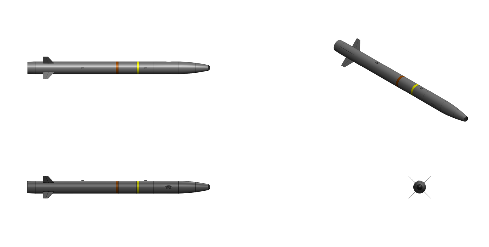
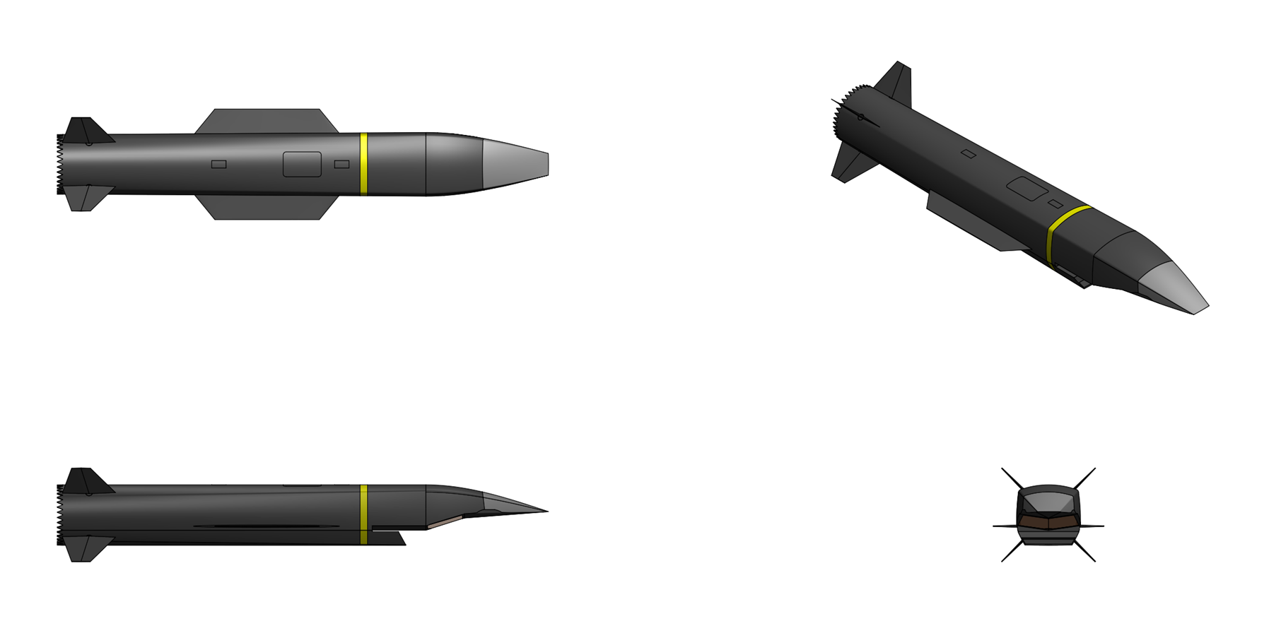
RBS 88 Waverider


General Characteristics:
Type:
Hypersonic Cruise Missile

Launch platform:
Aircraft

Guidance:
Stellar-inertial, GPS

Physical Characteristics:
Weight:
1,000 kg cruiser, 2,300 kg with booster

Length:
4.0 m cruiser, 6.3 m with booster

Diameter:
0.6 m

Payload:
RBS 88A:
4x Rb 71 loitering munitions

RBS 88B:
2x PC 100S hart target submunitions

Performance Characteristics:
Propulsion:
Dual mode scramjet (sustainer), solid fuel rocket (booster)

Speed:
Mach 8.0

Cruise altitude:
30,000 m

Range:
2,500 km


Overview:
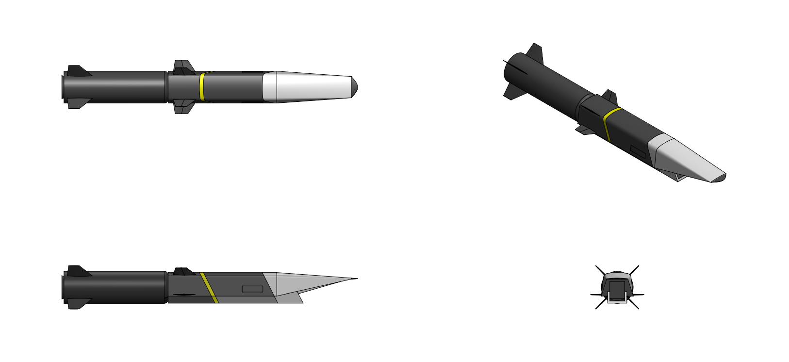
The RBS 88 Waverider cruise missile is a long range, air launched hypersonic cruise missile intended to penetrate heavily defended airspace and destroy hardened and time-critical high value targets deep inside protected enemy airpsace. The missile is a two-stage design consisting of a solid rocket booster stage and a scramjet-powered cruiser stage which carries one of two interchangeable payload modules: a pair of 100 kg class hart target submunitions for prosecuting hardened and deeply buried targets, or a quad pack of advanced autonomous powered loitering submunitions for engaging mobile IADS and TEL targets.


Airframe & Propulsion:
The Waverider is a two-stage missile consisting of a solid rocket booster (SRB) aft stage and a scramjet-powered cruiser forward stage. The solid rocket booster (SRB) stage provides the initial acceleration from captive carriage release conditions to the scramjet takeover conditions of approximately Mach 4.5 at 20,000 to 25,000 meters altitude. The booster is a single-stage solid propellant rocket motor with an interstage adapter that mates to the aft end of the cruiser stage. The booster weighs 1,300 kilograms and consists of a carbon fiber reinforced epoxy case containing approximately 1,000 kilograms of high energy solid propellant with a 90% solid loading consisting of 20% aluminum, 24% HMX, 46% AP, and 10% HTPB binder. The booster burns for 25 seconds with an average thrust of 95 kN. The booster is connected to the cruiser stage through a marman-clamp interstage adapter ring. Upon achieving scramjet takeover conditions (confirmed by the cruiser stage flight management computer via inertial measurement unit data), the interstage separation sequence is initiated. The marman clamp releases, and two pyrotechnic thruster assemblies mounted on the booster forward bulkhead push the booster cleanly aft and away from the cruiser.
Simultaneous with separation command, the cruiser stage scramjet engine fuel system initiates fuel flow to the engine, and the dual-mode scramjet transitions from ramjet pilot ignition to full ramjet operation within 1.5 seconds of fuel flow initiation. This overlap period is managed by the flight management computer to ensure continuous thrust during the booster-to-scramjet transition.

The cruiser stage employs a hypersonic lifting body derivative configuration. The forebody features a sharp-edged wedge-shaped compression surface that generates a planar shock wave, which is captured by the scramjet inlet located on the vehicle underside. The aftbody incorporates a single-expansion-ramp nozzle (SERN) that expands engine exhaust gases along the vehicle lower surface. The waverider-derived forebody is designed to operate efficiently across the Mach 4.5–8.0 speed range, encompassing the booster-to-cruiser transition regime through maximum cruise speed. The forebody compression ramp angle is set at 6.5 degrees, a design compromise between maximizing inlet pressure recovery at cruise Mach number and maintaining acceptable performance during ramjet-mode operation at lower Mach numbers. The leading edges of the forebody, inlet cowl, and control surfaces employ blunted geometries with radii selected to balance aeroheating loads against aerodynamic efficiency. The aerodynamic configuration provides a maximum trimmed lift-to-drag ratio (L/D) of approximately 3.5 at Mach 8.0 cruise conditions. The cruiser is constructed primarily from Ti-6242S (Ti-6Al-2Sn-4Zr-2Mo-0.1Si) near-alpha titanium alloy covered with an ablative silica phenolic based thermal protection system. The wedge shaped nose of the cruiser, which has to endure a leading edge temperature of over 1,600° C during Mach 8 cruise, is constructed from an Ultra-High Temperature Ceramic Matrix Composite (UHTCMC) composite consisting of hafnium diboride (HfB2) in a silicon carbide (SiC) fiber-reinforced matrix which is capable of sustained operation above 1700 °C. The four control fins of the cruiser are constructed from cast titanium-aluminide (TiAL) intermetallic alloy with UHTC coated carbon/carbon (C/C) leading edges.

The cruiser stage of the Waverider is powered by an SDI SRM 200 scramjet engine, a rectangular dual-mode scramjet (DMSJ) engine integrated into the underside the missile. . The vehicle forebody serves as the external inlet compression surface, generating an oblique shock system that pre-compresses freestream air before it enters the engine module. The engine module itself consists of an internal inlet section with additional compression, an isolator duct, a fuel injection and combustion section (combustor), and an internal nozzle/expansion section. The vehicle aftbody lower surface serves as the external single-expansion-ramp nozzle (SERN). The scramjet is fed using a fixed geometry two dimensional mixed compression nose inlet which consists of an aerodynamic compression ramp, sidewalls, a cowl lip, and an inlet duct which leads into the scramjet isolator. Downstream of the inlet, a constant-area isolator duct provides a buffer between the inlet and the combustor. The isolator during subsonic combustion (ramjet) mode at lower Mach numbers (Mach 3.5 to 5.0), the pre-combustion shock train generated by thermal choking in the combustor is contained within the isolator, preventing inlet unstart. The isolator length-to-height ratio (L/H) is 8.5, which provides adequate margin for shock train containment across the dual-mode operating range. The inlet ramp and isolator walls are fabricated from C/SiC CMC and are cooled by fuel routed through integrated catalytic heat exchanger/reactors (CHERs) where endothermic cracking of the hydrocarbon fuel is used to reduce the extremely high heat load experienced by the scramjet engine structure at hypersonic speeds. The combustor is a rectangular-section duct with a slight divergence to accommodate heat release and prevent thermal choking at the design cruise condition. Fuel injection is accomplished through a multi-stage system designed to optimize combustion efficiency across the full Mach range. Two recessed cavity flameholders are located on the (lower wall of the combustor. Fuel is injected upstream of each cavity through flush-wall sonic orifice injectors. The cavities provide a recirculating, near-stoichiometric, subsonic combustion zone that acts as a continuous ignition source for the main fuel injection. Downstream of the cavity flameholders, fuel is injected from the body-side and cowl-side walls through arrays of aerodynamic ramp injectors. Each aero-ramp injector consists of a pair of angled sonic orifices that generate counter-rotating streamwise vortex pairs in the supersonic crossflow, dramatically enhancing fuel penetration and mixing without the total pressure losses associated with physical strut or ramp injectors. The secondary injection provides the bulk of the fuel at the high-Mach cruise condition. A small set of pilot injectors with integral spark igniters are located at the forward end of the combustor, upstream of the primary cavities. These injectors supply a pre-cracked, highly reactive fuel fraction directly from the CHER system to ensure reliable ignition during the booster-to-scramjet transition and during any transient combustion events. The engine exhaust expands through an internal diverging duct section followed by the vehicle aftbody single-expansion-ramp nozzle (SERN). The internal nozzle provides initial expansion to a pressure ratio that prevents flow separation at the internal-to-external nozzle junction. The SERN lower surface is contoured to provide near-optimum expansion of the exhaust gases to ambient pressure at the design cruise altitude. Cowl-side closure of the SERN is provided by the freestream flow itself, creating an aerodynamic cowl. The nozzle forward section incorporates regenerative fuel cooling through passages machined into the carbon-carbon structure.

The dual mode scramjet engine that powers the Waverider is capable of operating as either a ramjet or scramjet, known as "dual-mode" operation. The dual-mode scramjet consists of four sections, an inlet, a constant volume isolator, a combustor, and a nozzle. The dual-mode scramjet is lit at Mach 4.5 and initially operates as a ramjet, decelerating the flow to subsonic speeds before combustion, with combustion taking place at constant pressure. As the Mach number is increased past 5 the the subsonic ramjet transitions into the dual-mode regime, where the combustor inlet Mach number is increased enough such that a thermal throat is created in the combustor and a pre-combustion shock train is generated. The isolator is designed to prevent this shock train from reaching the inlet to prevent inlet unstart which would choke the engine of airflow. In this regime the combustor operates in a mixed subsonic/supersonic, or dual-mode. As the Mach number is further increased past 6 the pre-combustion shock train moves out of the isolator and the combustor operates in the supersonic mode with combustion taking place at a constant volume, rather than at a constant pressure like in the subsonic combustion regime.

The scramjet engine is fueled with J9 high density synthetic endothermic hydrocarbon fuel which undergoes thermal cracking at high temperatures in the presence of a catalyst, undergoing catalytic dehydrogenation and yielding hydrogen gas and new hydrocarbon compounds while absorbing a significant amount of heat without forming any surface deposits. The Catalytic Heat Exchanger/Reactor (CHER) system consists ofmcompact, engine-integrated heat exchanger units in which the fuel flows through catalytic passages in intimate thermal contact with the hot engine structure walls. As the fuel absorbs heat, it reaches temperatures at which endothermic catalytic cracking reactions are initiated, breaking the long-chain hydrocarbon molecules into shorter-chain species (ethylene, propylene, methane, hydrogen) through dehydrogenation and carbon-carbon bond scission reactions. These endothermic cracking reactions are strongly heat-absorbing, providing a chemical heat sink that approximately doubles the effective cooling capacity of the fuel compared to sensible heating alone. The cracked fuel products (a mixture of lighter hydrocarbons and hydrogen) are then injected into the combustor, where they offer superior ignition and combustion characteristics compared to uncracked J9, due to their lower molecular weight, higher diffusivity, and the presence of highly reactive species such as hydrogen and ethylene. The catalytic heat exchanger/reactors (CHERs) constructed from beta 21S (15Mo2.7Nb3Al0.2Si) beta titanium alloy located inside the C/SiC walls of the engine. The B21S titanium alloy is insulated from the C/SiC walls with a small air gap, ensuring the beta 21S titanium stays within its 675° C operating temperature. The CHERs are constructed as brazed plate-fin heat exchanger assemblies fabricated from beta 21S with the fuel side passages being coated with a zeolite-supported platinum-rhenium (Pt-Re/ZSM-5) catalyst that promotes the desired endothermic cracking reactions at temperatures above 480°C . The hot-side passages interface directly with the engine structure walls (combustor walls, isolator walls, and inlet aft walls), receiving heat by conduction where the catalyst and the radiant heat from the C/SiC scramjet walls causes the J9 to decompose into hydrogen, cyclohexene, and various alkylcyclohexenes. The CHER system is distributed across three zones within the engine module, sized according to the local heat flux distribution. Two CHER panels are integrated into the isolator sidewalls and cowl-side wall and pre-heat the fuel to approximately 300–400°C with limited cracking (5–10% conversion). Fuel exiting the isolator CHERSs is split between the subsequent combustor CHERs and the the pilot injectors. Four CHER panels are integrated into the combustor body-side and cowl-side walls. Fuel enters at 300–400°C from Zone 1 and exits at 600 to 700°C with 40–60% endothermic cracking conversion. Finally a conventional regenerative cooling jacket (not catalytic) in the forward portion of the internal nozzle, where fuel absorbs additional heat before being routed to the secondary (aero-ramp) fuel injectors. The J9 fuel is stored in two conformal fuel tanks located within the cruiser stage body, forward and aft of the payload bay. Total fuel capacity is approximately 600 kg. Fuel is pressurized by a turbin -driven fuel pump, which is powered by a small turbine driven by hot, partially cracked fuel bled from the isolar CHER outlet. The fuel system operates at pressures of 60 to 80 bar throughout the cooling and injection circuits to suppress fuel coking and vapor formation at elevated temperatures. A fuel management controller (FMC) continuously monitors fuel temperatures, pressures, and flow rates at multiple points in the system, and modulates fuel flow splits between the CHER zones and fuel injection stages to maintain thermal equilibrium. The FMC operates under the authority of the vehicle flight management computer (FMC) and receives real-time engine health monitoring data from thermocouples and pressure transducers distributed throughout the engine flowpath.


Guidance:
The Waverider is guided in flight by a stellar-inertial guidance system which provides highly accurate midcourse guidance without reliance on GPS signals. The guidance system consists of a 6-axis SDI TNS 450 tactical-grade timing and inertial measurement Unit (TIMU) which combines three milli-Hemispherical Resonator Gyroscope (mHRG) and three quartz resonating beam accelerometers (RBA) in a low SWaP package (500 cc volume, <1.0 kg mass, <5 watts max power consumption) package which provides <0.0003°/√hr gyro angle random walk and < 0.0001 °/hr bias stability performance coupled to a CCD star-tracker camera which looks upward through a circular window located in the upper fuselage of the cruiser stage. The star tracker employs is uses to provide position fixes in flight accurate to within 90 meters in broad daylight using a pre-programmed 57 star catalog. The IMU and stellar sensor are further augmented by a 48 channel dual-frequency (L1/L2) SAASM (Selective Availability Anti-spoofing Module) based GPS receiver with M-Code compatibility and >90 dB J/S digital anti-jamming capability whuch employs twin controlled reception pattern antennas (CRPAs) on the aft fuselage of the cruiser with adaptive beam steering and directional nulling capability with ionosphere correction capability and simultaneous L1/L2 operation which provides the weapon with <1 meter position accuracy capability. in heavy GPS jamming environments.


Warhead:
RBS 88A: The RBS 88A is designed to attack time-critical relocatable targets including mobile surface-to-surface and surface-to-air missile batteries and dispenses a payload of four Rb 71 loitering autonomous submunitions onto the target area. Each Rb 71 submunition weighs 45 kilograms and consists a maneuvering airframe 90 centimeters long with a 1.2 meter wingspan powered by a small turbojet engine which contains a solid state LADAR sensor with automatic target recognition (ATR) capability coupled with a multimode explosively formed penetrator warhead. The Rb 71 is powered by a 130 N thrust SDI RM55 micro-turbojet engine which gives the munition a maximum speed of 430 kph (Mach 0.30) an an altitude of 250 meters AGL with a maximum range of 185 kilometers and a maximum flight endurance of 30 minutes. The munition's seeker consists of a solid state three-dimensional imaging LADAR sensor employing an uncooled, diode pumped Nd:YVO4 laser with a 1.06 μm wavelength. The LADAR seeker is capable of acquiring vehicle size targets at a range of 6 km in clear weather and produces high resolution 3D imagery which is processed by an automatic target recognition processor which compares the LADAR image to a database of threat vehicles. When the munition identifies a target it cuts its turbojet engine and glides towards the target to a point directly overhead where the munition's downward firing explosively formed penetrator (EFP) warhead is then fuzed. The warhead weighs 8.0 kilograms including 2.5 kg of polymer bonded explosive (92% HNIW, 4.8% BDNPA/F, 3.2% CAB) and can be miniated in one of three modes depending on target type and standoff range. Against armored targets the warhead is fired in a long rod penetrator mode which is designed for maximal armor penetration. Alternatively if fuzed from a greater altitude over the target the warhead is fired as an aerostable slug which maintains aerostability over greater standoff ranges while still having the capability to penetrate the thinner roof armor of most vehicles. Against softer targets such as TELs or radars the warhead is used in a directed fragmentation mode which causes the tantalum liner to break up into shrapnel which is projected towards the target area like a large shotgun blast.

RBS 88B: The RBS 88B is designed to penetrate and destroy hardened aircraft shelters, command bunkers, and other hard targets and contains a payload of twin PC 100S bombs which are released from the cruiser stage at high supersonic velocity prior to impact. Each PC 100S weighs 110 kilograms and employs a 100 kilogram hardened penetrator warhead consisting of a nickel-molybdenum-cobalt maraging steel (8Ni-14Mo-20Co-Fe) sub-caliber penetrating warhead filled with 20 kilograms of enhanced blast thermobaric explosive (50% HMX, 30% Al powder, 20% PCP/TMETN energetic binder/plasticizer). The warhead is fitted with a base mounted hard target smart fuze (HTSF) containing a precision MEMS accelerometer and micro-controller which features void sensing, layer counting, depth of penetration, and time time delay after impact fuzing modes. The detonator is entirely electronic with no moving parts and uses an exploding foil initiator (EFI) detonator to initiate the main explosive charge. The warhead is coupled to a guidance and control section consisting of a 6-axis SDI TNS 400 MEMS based inertial measurement unit along with a control section featuring three flip-out grid fins actuating using brushless DC electro-mechanical servomotors. With a terminal impact velocity of over 1,000 meters per second (mach 4) each PC 100 munition is capable of penetrating over 4 meters of 34 MPa (5,000 psi) reinforced concrete before exploding.
Last edited by The Technocratic Syndicalists on Mon May 11, 2026 12:47 pm, edited 28 times in total.
SDI AG
Arcaenian Military Factbook
Task Force Atlas
International Freedom Coalition


OOC: Call me Techno for Short
IC: The Kingdom of Arcaenia

User avatar
The Technocratic Syndicalists
Minister
 
Posts: 2350
Founded: May 27, 2015
Inoffensive Centrist Democracy

Postby The Technocratic Syndicalists » Thu Jul 14, 2016 5:52 pm

Image


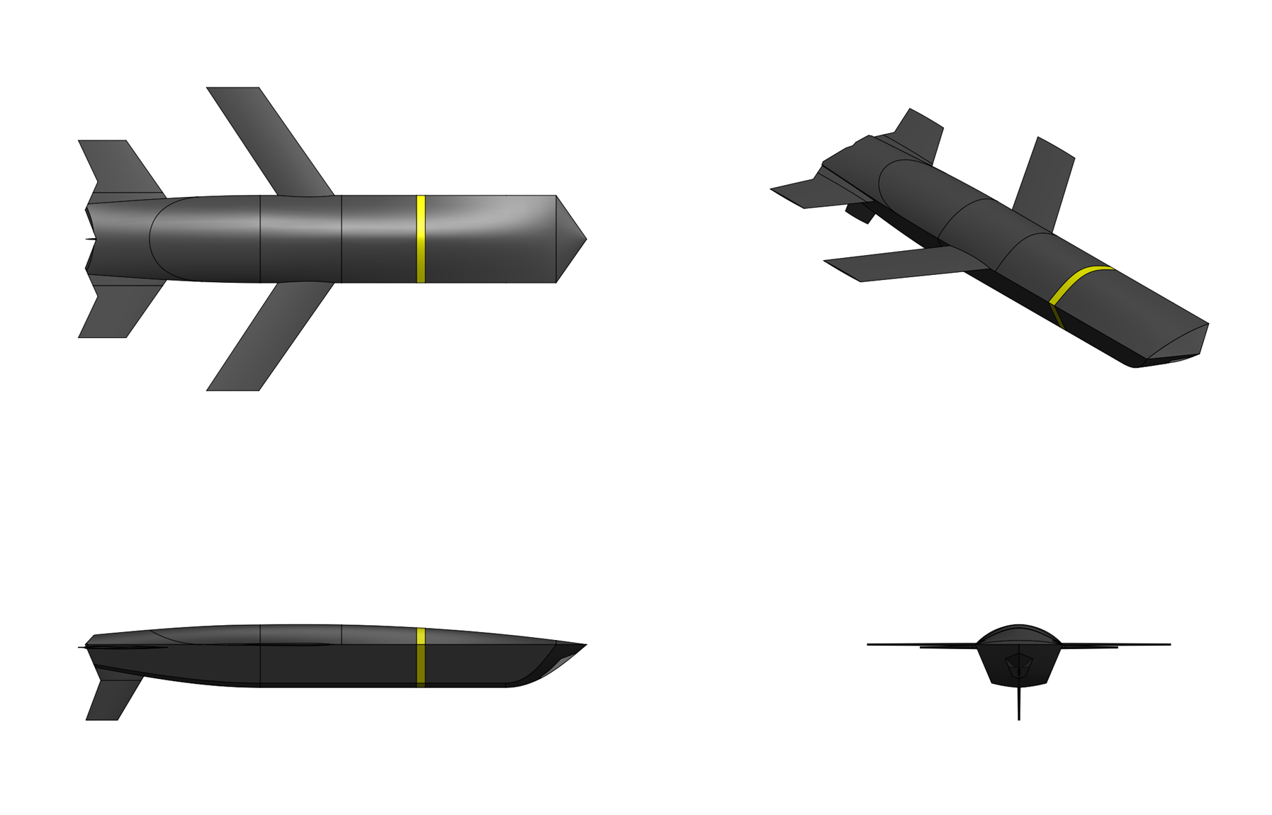
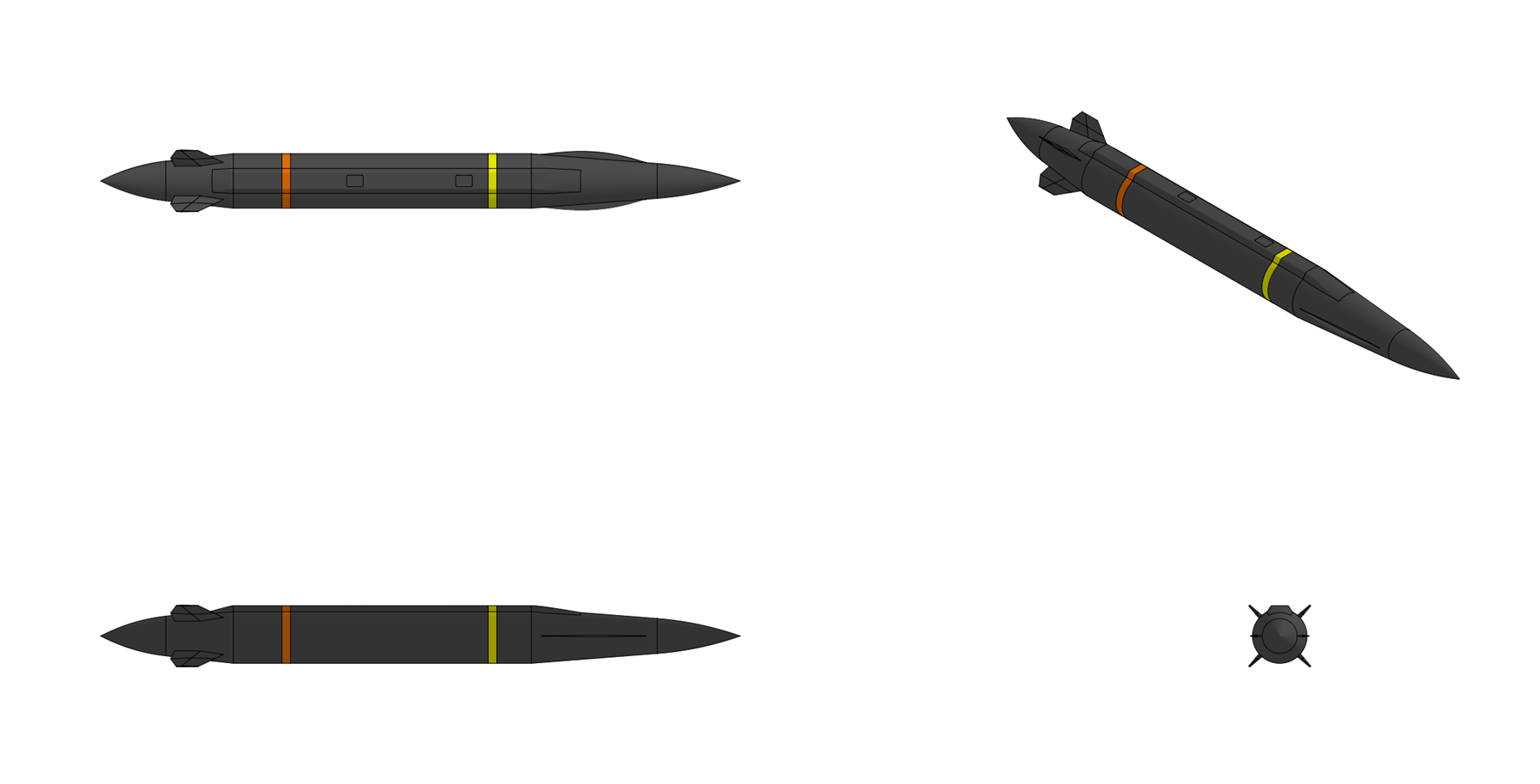
RBS 96 Stormrider


General Characteristics:
Type:
Stealth Cruise Missile

Launch platform:
Aircraft

Guidance:
PTAN, INS/GPS

Physical Characteristics:
Weight:
2,400 kg

Length:
6.7 m

Diameter:
0.75 m

Warhead:
    RBS 96A:
    SG 87 nuclear warhead, 200 kt

    RBS 96B:
    SG 89 nuclear earth penetrator, 400 kt

    RBS 96C:
    1,400 kg blast-fragmentation

Performance Characteristics:
Propulsion:
Turbofan

Speed:
Mach 0.9

Range:
    RBS 96A:
    7,400 km

    RBS 96B:
    3,700 km

    RBS 96C:
    1,800 km


Overview:
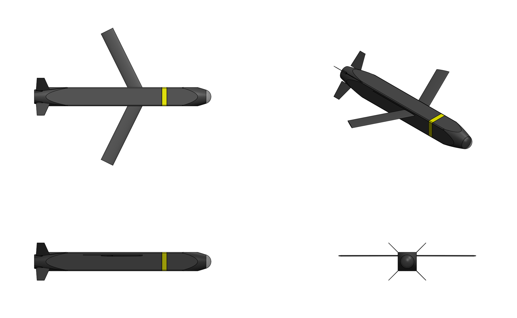
The RBS 96 Stormrider is a long range, air launched, low-observable, turbo-fan powered nuclear-capable subsonic cruise missile designed by SDI Missile Systems. Compared to previous generations of subosnic, air launched nuclear cruise missiles the RBS 96 is designed to be harder to detect, and has significantly greater range and accuracy.


Airframe
The Stormrider features a broad-band low-observable stealth design intended to minimize it's RCS against both high band targeting and fire control radars and low band surveillance radars when viewed from ahead or above. The stealth design is primary designed to defeat the radar systems of airborne AWACS and interceptor aircraft and concentrates the radar signature into two large spikes 90 degrees on either side of the center-line, placing the majority of the missile's radar signature into it's doppler notch. The missile features a long cylindrical fuselage with a sharp, chined nose cone along with forward-swept wings and trapezoidal tail fins intended to minimize it's frontal RCS. The control surfaces of the missiles consist of two forward swept supercritical airfoil wings, two forward swept all-moving horizontal stabilizers, and a single all-moving horizontal stabilizer which is offset from the centerline of the missile. The air inlet for the missiles' turbofan engine is a serpentine S-duct flush with the underside of the missile which hides the engine compressor blades from view by airborne radar systems. The exhaust is a flat, 2-D mixer design located underneath the fuselage which mixes the hot exhaust with ambient air to reduce the missile's infrared signature and hides the hot exhaust from view by airborne IRST (Infra-red search and track) systems from above. The skin, wings, tails, and inlets of the missile are constructed from graphite/epoxy composite and feature an embedded radar absorbing material (RAM) consisting of two layers of FeNi nanopowder coated multiwall carbon nanotubes embedded into a thermoset epoxy resin which is cured into the missile's graphite/epoxy structure. The exhaust duct of the missile is further lines with a high temperature high temperature ceramic RAM made from three-dimensional reinforced carbon/carbon (C/C) three-dimensional with embedded layers of multilayered carbon nanotubes embedded with iron nanopowder. The combination of stealth shaping and RAM results in the missile having an average frontal sector radar cross section of around -40 dBsm (0.0001 m2).


Propulsion
  • Name: SDI RM415
  • Type: Low Bypass Turbofan
  • Length: 750 mm
  • Diameter: 300 mm
  • Dry Weight: 70 kg
  • Bypass Ratio: 3:1
  • Compressor: 1 stage fan, 2 stage axial + 1 stage centrifugal HPC
  • Combustor: Annular combustor
  • Turbine: 1 stage HPT, 2 stage LPT
  • Maximum rhrust: 5.0 kN
  • Overall pressure ratio: 26:1
  • Turbine inlet temperature: 1,400° C
  • Specific fuel consumption: 20 g/Kn-s
  • Thrust-to-Weight Ratio: 8.6:1
The Stormrider is powered by an SDI RM415 twin-spool medium-bypass turbofan generating a maximum of 5.0 kN of thrust. The highly compact RM415 engine combines good fuel efficiency with a high thrust-to-weight ratio which allows the Stormrider missile to be both long ranged and highly maneuverable in flight. The RM415 configuration consists of a single stage fan driven by a two-stage LP turbine supercharging a two stage axial plus one stage centrifugal HP compressor which is driven by a single stage HP turbine. The two engine spoo;s are counter-rotating to minimize gyroscopic and shaft vibration effects. The combustor is a high efficiency double annular combustor with rotary fuel injection. To reduce engine mass and improve thermodynamic efficiency the RM415 engine uses a variety of advanced composite elements including carbon fiber reinforced polyamide composite fan blades, fan casing, and HPC casing, silicon carbide reinforced titanium metal-matrix composite shafts and silicon nitride ceramic bearings, turbine blades, turbine vanes, combustor, and nozzle. The use of high temperature ceramic turbine blades removes the need for turbine blade cooling, reducing the weight and complexity of the engine. The high temperature ceramic turbine also permits a higher turbine inlet temperature, improving specific power and efficiency. Valves and fuel nozzles in the engine are constructed from 3D printed cobalt-titanium alloy using a Direct Metal Laser Melting Machine (DMLMM) machine.


Guidance:
The RBS 96 missile employs a hybrid guidance system which combined a high accuracy precision terrain aided navigation (PTAN) based terrain reference navigation system, a laser doppler velocimeter (LDV), and a high accuracy inertial navigation system coupled to a GPS receiver system. The precision terrain aided navigation (PTAN) based guidance system is a type of enhanced terrain reference navigation system which requires fewer position updates and achieves a higher position accuracy than legacy TERCOM systems. The missile is equipped with three Ku band (13.575 GHz center frequency), solid-state, low probability of intercept (LPI) interferometric synthetic aperture radar altimeters blended into the underside of the missile which provide missile altitude above ground level measurements and generate highly accurate interferometric Doppler radar ground return data which is then correlated with a digital elevation map (DEM) to determine the missile's position in flight. The system employs synthetic aperture processing and uses a third antenna as an interferometer to determine the across-track angle to the earliest radar returns, the combination of SAR and interferometry making it possible to accurately determine the arrival direction of the echoes both along and across the missile ground trac by comparing the phase of one receive channel with respect to the others which is used to derive the height of the surface from the range measurement of the radar. The generated radar profile data is then correlated with digital elevation map data, the system further weighting the terrain correlated position solution based on a digital elevation map resolution and combining the position solution from the inertial navigation unit with the weighted terrain correlated position solution into a navigation position solution, the system allowing the missile's in flight location to be determined within 3 meters accuracy when using DTED Level 4 maps. Low transmit power of the radar altimeters and use of spread-spectrum, frequency modulated continuous waveform (FMCW) operation minimize the risk of missile detection by hostile ECM systems. The laser doppler velocimeter provides the guidance set with accurate measurements of the air missile's ground velocity to further reduce navigation error. The LDV is mounted to the bottom of the guidance set in the missile's nose and comprises a CO2 laser, beam forming and pointing optics, a laser detector, and signal processing electronics. The laser beam is expanded and transmitted through a window in underside of the missile's nose to the ground where light scattered by the ground is collected by the telescope and focused on the detector. The Doppler signal at the detector output is then processed by the signal processing electronics, the computed velocity ground velocity then being transmitted to the navigation unit for velocity updating. The missile's INS consists of an SDI TNS 900 tactical inertial measurement unit, an enhanced 6-axis laser-ring gyro based inertial measurement unit designed by SDI Missile Systems which consists of three laser ring gyros and three monolithic quartz structure vibrating beam accelerometers contained a compact, low SWaP (170050 cc volume, <2.5 kg mass, <10 watts max power consumption) package which provides aircraft gyrocompass based performance with <0.003°/√hr gyro angle random walk and <0.1 °/hr bias stability performance. The TNS 900 IMU is further coupled to a 48 channel dual-frequency (L1/L2) SAASM (Selective Availability Anti-spoofing Module) based GPS receiver with M-Code compatibility and >90 dB J/S digital anti-jamming capability. The GPS system employs twin controlled reception pattern antennas (CRPAs) with adaptive beam steering and directional nulling capability located on the missile upper fuselage which along with ionosphere correction capability provided simultaneous L1/L2 operation provides the weapon with <2 meter position accuracy in heavy GPS jamming environments.

During flight the missile is designed to fly through several timing control waypoints along its preprogrammed course where the missile performs terrain following using the PTAN system during designated portions of the mission. The navigation system is also updated at various points with missile velocity information from the LDV. In a typical mission the missile will take position updates from four PTAN maps: a landfall map, two enroute maps and a terminal map. The missile then navigates to the target where it detonates its' warhead at a preprogrammed height of burst or dives onto the target with a preprogrammed terminal descent angle. The launch aircraft provides initialization, IMU transfer alignment, and mission profile data to the missile guidance set via the umbilical assembly while the missile is being carried internally. Upon separation from the aircraft's rotary launcher or external pylon the missile guidance set processes steering and engine control commands to navigate along the pre-planned mission route to the target. Missions can eitherbe terrain aided where PTAN updating is utilized, or free inertial where only the INS and GPS receiver are used. The missile guidance system memory unit can store up to 192 3-D waypoints and 10 PTAN map areas which the ability to flex-target the missile to different targets or through a different trajectory during flight.


Warhead:
RBS 96A: The baseline RBS 96A missile is fitted with an SG 87 nuclear warhead, a two-stage thermonuclear warhead with a design yield of 200 kilotons. The SG 87 is designed to incorporate modern nuclear weapon safety features including insensitive high explosives, fire-resistant pits, type V permissive action link (12 digit code length with third failed attempt lockout) and advanced detonator safety systems including a strong link/weak link detonation chain safety mechanism. The primary employs a highly insensitive explosive consisting of 95% TATB (triaminotrinitrobenzene) and 5% PCTFE (Polychlorotrifluoroethylene) thermoplastic chlorofluoropolymer binder while the primary uses a fire resistant pit employing a vanadium coated 97.5 wt% plutonium-239 supergrade plutonium primary with a pit design intended to provide 1000° C molten plutonium containment capability. The complete SG 87 warhead is 34 centimeters in diameter, 100 centimeters in length, and has a mass of 150 kilograms.

RBS 96B: The RBS 96B missile replaces the SG 87 warhead with an SG 89 earth penetrating nuclear warhead intended to defeat strategic hard and deeply buried targets HDBTs). The SG 89 consists of a two-stage thermonuclear warhead packaged in a high strength maraging steel penetrating case which is designed to allow the warhead to penetrate and detonate below the earth's surface, creating a massive shock wave capable of destroying underground targets. Like SG 87 the SG 89 is designed to incorporate modern nuclear weapon safety features including insensitive high explosives, fire-resistant pits, type V permissive action link (12 digit code length with third failed attempt lockout) and advanced detonator safety systems including a strong link/weak link detonation chain safety mechanism. The primary employs a highly insensitive explosive consisting of 95% TATB (triaminotrinitrobenzene) and 5% PCTFE (Polychlorotrifluoroethylene) thermoplastic chlorofluoropolymer binder while the primary uses a fire resistant pit employing a vanadium coated 97.5 wt% plutonium-239 supergrade plutonium primary. The penetrator external geometry is a 3.0 CRH ogival nose, a cylindrical aft-body, and a gradual conical flare to the back face of the penetrator. The complete SG 89 warhead with its penetrating case is 27 centimeters in diameter (30 cm at the end of the aft flare) and 140 centimeters long and weighs 400 kilograms. With an impact velocity of 300 m/s the warhead is capable of penetrating 2.0 meters of medium-strength rock, 5 meters of low-strength rock, and 40 meters of silty clay. The SG 89 has a design yield of 300 kilotons and when detonated at a 3 meter DOB produces damage to underground structures equivalent to a 5 to 6 megaton surface-burst of the same accuracy. The arming system of the warhead is designed to survive a 10,000 g peak deceleration load and uses the penetrator case and aft bulkhead as the exclusion region which is established with associated stronglink and weaklink protections to protect against inadvertent electrical energy getting to the detonators. Energy transfer to the detonators is achieved through a magnetically coupled transformer which is normally blocked by discriminator protected stronglinks. The power to perform the fuzing functions is stored in a keep-alive supercapacitor which is charged by thermal batteries when the Capacitive Discharge Unit (CDU) is charged. A Penetration Sensor and a Sequencer are used to fuze the system, detonating the warhead at the intended penetration depth

RBS 96C: The RBS 96C is a conventional version of the RB 96 which replaces the nuclear warhead with a 1,400 kg conventional high-explosive blast/fragmentation warhead. The warhead consists of a steel case 60 centimeters in diameter and 270 centimeters long and is filled with approximately 900 kilograms of RDX/AP/Al/HTPB insensitive high-blast thermobaric explosive. The software of the RBS 96C is designed to support three different attack modes: a direct attack profile flyting directly into the side of the target, a pop-up followed by a terminal-dive maneuver to impact the target vertically, and a PWD (Programmed Warhead Detonation) mode where the warhead is detonated while the missile is flying directly over the target, effective against targets behind a protective shielding or against soft targets such as air defense radars or parked aircraft.
Last edited by The Technocratic Syndicalists on Sun Mar 29, 2026 5:14 pm, edited 51 times in total.
SDI AG
Arcaenian Military Factbook
Task Force Atlas
International Freedom Coalition


OOC: Call me Techno for Short
IC: The Kingdom of Arcaenia

User avatar
The Technocratic Syndicalists
Minister
 
Posts: 2350
Founded: May 27, 2015
Inoffensive Centrist Democracy

Postby The Technocratic Syndicalists » Mon Jul 18, 2016 10:27 pm

Image


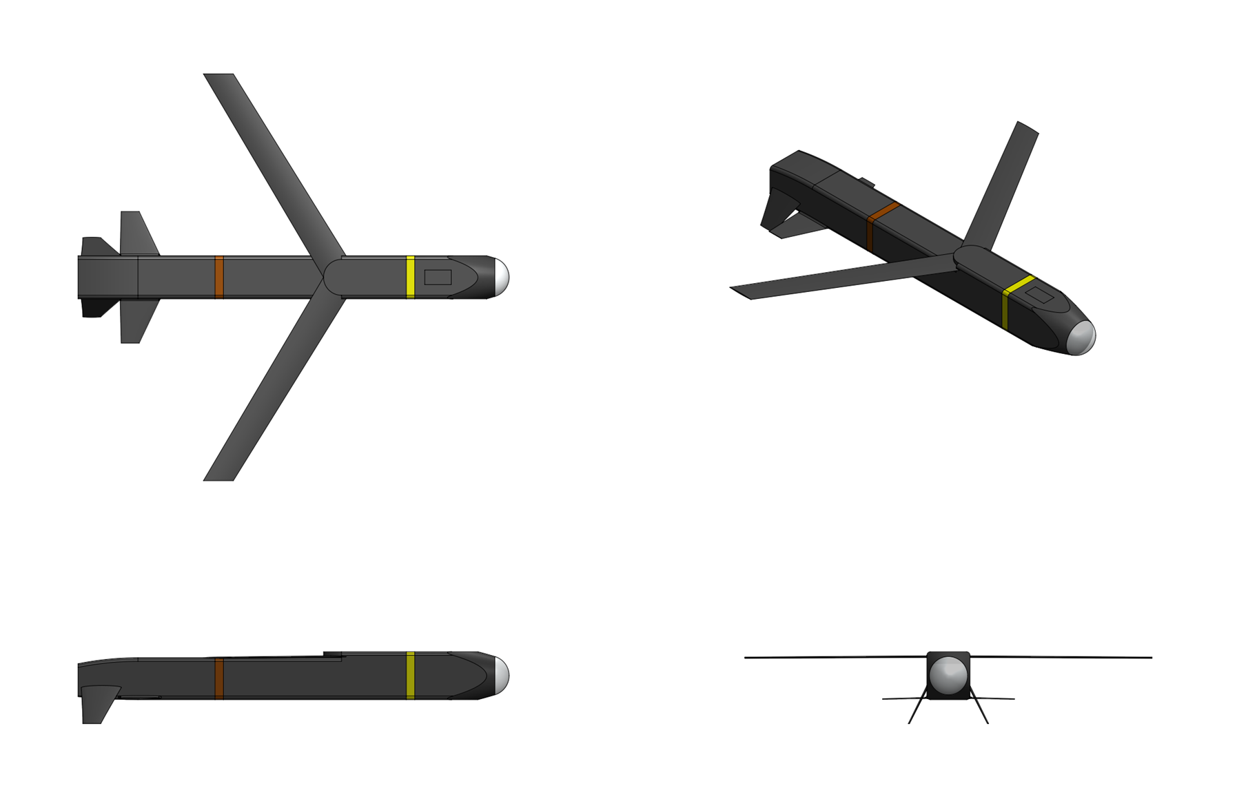
RBS 95 Broadsword


General Characteristics:
Type:
Anti-ship and land attack hypersonic cruise missile

Launch platform:
VLS, TEL

Guidance:
Combined active/passive RF seeker, INS/GPS, 2-way RF datalink

Physical Characteristics:
Weight:
1,500 kg (cruise stage), 2,500 kg (with booster)

Length:
5.0 m (cruise stage), 7.0 m (with booster)

Diameter:
0.6 m

Warhead:
500 kg reactive fill penetrator

Performance Characteristics:
Propulsion:
Dual-combustion Ramjet

Speed:
Mach 6.5 (high altitude)

Range:
1,000 km (Mach 6.0 @ 25,000 meters)
1,500 km (Mach 4.0 @ 20,000 meters)


Overview:
The RBS 95 Broadsword is a hypersonic anti-ship and lack attack cruise missile designed by SDI Missiles & Fire Control Systems.


Airframe
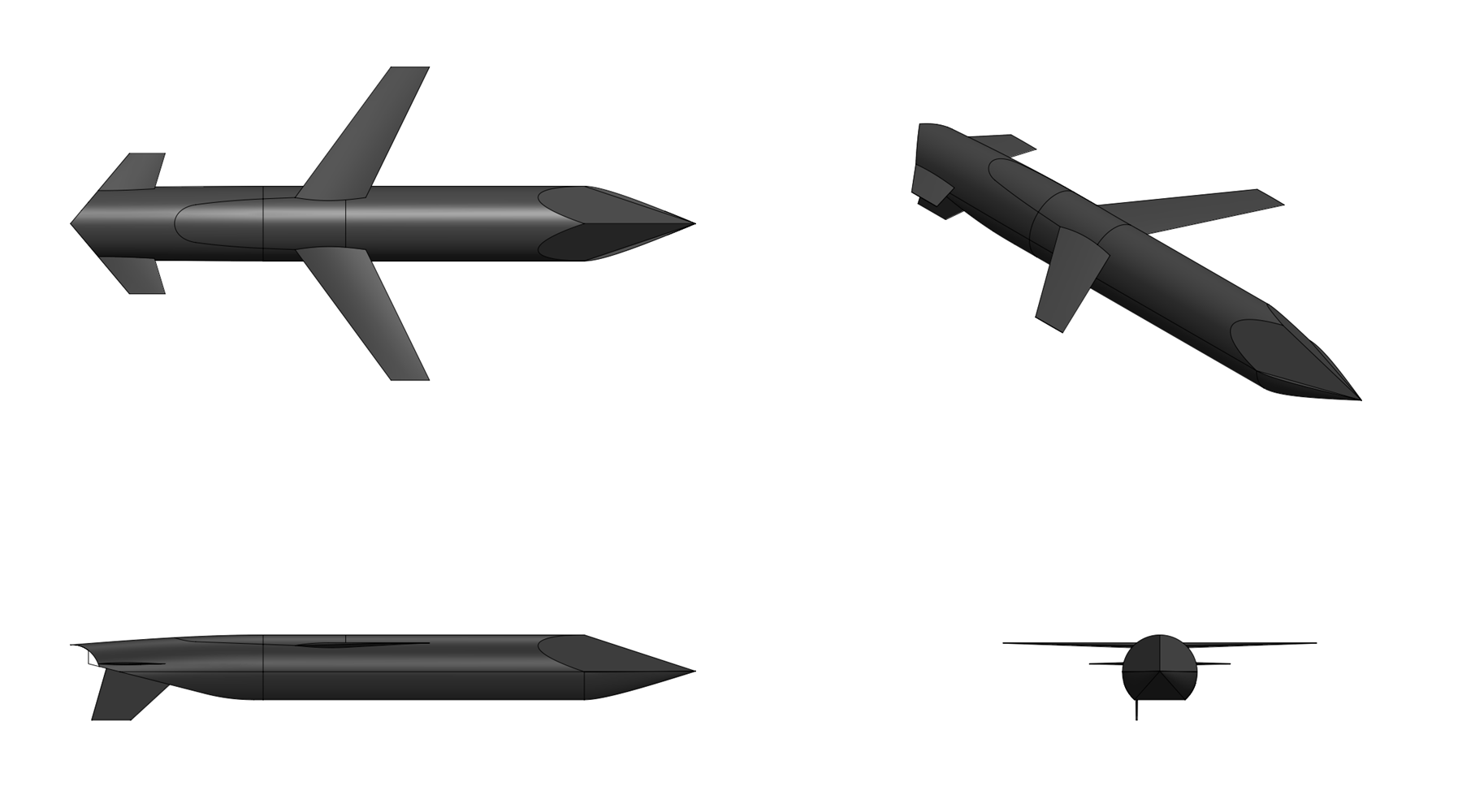
The RBS 95 is an axisymmetric missile with a cruise stage featuring multiple inward-turning scoop inlets located in the compression field of a conical forebody. These inlets split the air to feed a subsonic dump combustor and a tandem supersonic combustor. All of the fuel is added to the subsonic combustor, which heats and partially cracks the fuel. The fuel-rich effluent provides the core flow for mixing with the annular supersonic inlet supply in the supersonic combustor. This design burns unprocessed liquid hydrocarbon fuel and relies on high-temperature materials and insulation for the engine and airframe structure. A slip-in booster boosts the missile to a take-over Mach number. The missile is divided into seeker & guidance section, warhead section, dual-combustion ramjet propulsion section, integral fuel tank section, nozzle & aft body section, and booster section. The forward seeker & guidance section is integrated into the missile's conical forebody and contains the missile's seeker and seeker electronics, the GPS/INS midcourse navigation unit, the mission computer, datalink transceiver, and the power conditioning unit. The nose radome is a hot-pressed silicon nitride (Si₃N₄) radome with a CVD diamond-like carbon erosion coating. The dual-combustion ramjet propulsion section houses the dual combustion ramjet engine including the forward subsonic preburner zone and aft supersonic main combustor zone, the fuel injection system for both zones, the catalytic endothermic fuel pre-heater, and the flameholding and ignition systems. The integral fuel tank section surrounds the dual combustion ramjet engine and contains the missile's endothermic hydrocarbon fuel blend with positive-expulsion elastomeric bladder, anti-slosh baffles, and fuel-line routing to the regenerative cooling jacket and the two DCR combustion zones. The fuel tank’s double-wall construction provides structural fuel containment within a load-bearing outer shell, with fuel passages integrated into the wall annulus for regenerative cooling of the tank exterior skin. The nozzle & aft Body section contains the missile's fixed-geometry convergent-divergent exhaust nozzle with a carbon-carbon composite exit cone, the four EHA tail-fin actuators, and booster nozzle insert ejection mechanism.


Propulsion
[list]The Broadsword missile employs a cruising stage with a dual combustion ramjet (DCR) engine, an air-breathing propulsion system which provides efficient and stable operation across a full Mach 3.0 to 6.5 flight envelope using conventional liquid hydrocarbon fuel. The missile has six intakes including four supersonic intakes (positioned at the 2, 4, 8, and 10 o’clock positions) and two subsonic intakes (positioned at the 3 an 9 o’clock positions) which feed separate combustion chambers. The engine uses two separate combustion zones, each fed by its own seperate inlet system, to achieve stable and efficient thrust production across a speed range that spans conventional ramjet (subsonic combustion only) through full scramjet (supersonic combustion only) operation. The subsonic preburner is a conventional ramjet combustion chamber located in the forward section of the engine, fed by two scoop inlets. Incoming air is decelerated to subsonic speed (Mach 0.3–0.5) through a divergent diffuser section before entering the preburner, where it mixes with injected endothermic fuel and burns in a recirculation-stabilized flame. During low-speed operation (Mach 3.0–4.0) the preburner produces the majority of the engine’s thrust by operating as a conventional subsonic-combustion ramjet, with high combustion efficiency (>95%) and flame stability. At higher speeds (Mach 4.5–6.5), the hot, fuel-rich exhaust from the preburner is injected into the supersonic main combustor, serving as a continuous pilot flame and ignition source for the supersonic combustion zone. The supersonic main combustor is the aft combustion zone and is fed by four supersonic mixed compression inlets. At Mach 5.0 and above, air entering through these inlets is decelerated to approximately Mach 2.0–2.5 by the inlet compression system where the supersonic airflow enters the main combustor, where it is mixed with directly injected endothermic fuel and ignited by the hot preburner exhaust plume that enters the main combustor rom upstream. Combustion occurs at supersonic speed (scramjet mode), enabling efficient thrust production at Mach 5–6.5. The main combustor uses a combination of strut-based and wall-mounted fuel injectors arranged in two axial stages to achieve complete fuel-air mixing within the available combustor length. At Mach 3.0–4.0, the engine operates primarily as a subsonic-combustion ramjet, with the preburner generating most of the thrust. As the missile accelerates through Mach 4.0–5.0, fuel is progressively shifted from the preburner to the main combustor injectors, and the engine transitions to a blended dual-combustion mode where both zones contribute thrust. Above Mach 5.0, the majority of fuel is injected into the supersonic combustor for scramjet operation, while the preburner is throttled back to a pilot-flame level (approximately 10–15% of total fuel flow) to maintain flame stability in the main combustor.

The missile uses an endothermic hydrocarbon fuel blend (70% methylcyclohexane / 30% J9), with enhanced catalytic processing. The fuel serves As propellant, coolant, and endothermic heat sink. Fuel is drawn from the bladder tank during Mach 6 cruise by a turbine-driven pump (powered by combustion-gas bleed from the preburner) where it then passes through the regenerative cooling jacket surrounding the main combustor outer wall, absorbing conducted heat while MCH and J9 undergoes catalytic dehydrogenation (using an enhanced ruthenium/platinum bimetallic catalyst on an alumina-zirconia support) to produce toluene and hydrogen. The decomposed fuel mixture (at approximately 400°C) is then split into three streams: approximately 70% to the main combustor injectors, approximately 15% to the preburner injectors, and approximately 15% to the nozzle throat cooling circuit. The hydrogen-rich fraction significantly enhances combustion kinetics in the supersonic combustor, where flame speed and ignition delay are critical constraints.


Guidance & Navigation:
The RBS 95 missile employs a dual-mode seeker system which combines a multi-mode Ka band imaging radar seeker and a wideband passive radar seeker. The Ka band (34-36 GHz) imaging radar seeker is optimized for all-weather detection and engagement of surface ship and moving land targets and operates in three modes; real beam, doppler beam sharpened (DBS), and synthetic aperture radar (SAR). The real beam and DBS modes are used for wide area search while high range resolution (HRR) profiling techniques used in the real beam mode for high resolution target recognition and classification. The synthetic aperture radar (SAR) mode is used for midcourse guidance and provides high resolution imagery to refine the target classification of detected targets.

The seeker employs a digital active phased array antenna using a digital beamformer, digital MEMS phase shifters, and gallium nitride (GaN)-on-SiC T/R modules and is scanned electronically in elevation and azimuth with +/- 60° off-boresight azimuth and elevation scan capability. The seeker generates and transmits randomized low-power noise signals to detect targets, a copy of each generated randomized noise signal being stored in the seeker's active memory as to allow correlation with incoming signal returns. The high instantaneous bandwidth of the seeker (>1 GHz) combined with randomized noise signals results in extremely high range resolution and allows for both simultaneous measurement of range and doppler shift of the target. The extremely high range and doppler resolution of the seeker support clutter discrimination in littoral or other high clutter environments as well as automatic target recognition (ATR) and aimpoint selection capability. The use of a digital beamformer also enables the use of adaptive beamforming which along with super resolution algorithms enables the seeker to accurately recognize, locate, and suppress jammer sources while performing target acquisition and tracking tasks. Additional ECCM features of the seeker include low transmit power, narrow beam-width transmissions, and a dual polarized antenna to counter angle deception jamming. The passive radar seeker is mounted behind the Ka band radar seeker in the missile's nose radome and consists of a two planar spiral high band antennas and an eight element low band antenna array providing 2-40 GHz emission detection, identification, and direction finding capability which covers typical surface ship air search, navigation, and fire control radar bands. The passive radar seeker alloys the missile to approach emitting targets radar silent, only using the active radar seeker for terminal homing and target aim-point selection.

The seeker assembly is coupled with a midcourse guidance unit (MGU) which contains a 2-way satellite communications datalink and a GPS/INS autopilot system combining a 6-axis strapdown inertial measurement unit with three laser-ring gyroscopes (LRG) and three quartz resonating beam accelerometers (RBA) with a 24 channel dual-frequency (L1/L2) SAASM (Selective Availability Anti-spoofing Module) based GPS receiver. The autopilot unit provides for highly accurate 3D waypoint based terminal navigation and allows for engagement of stationary land targets using GPS grid-coordinates which can be uploaded to the missile before or after launch. Wide-area differential GPS (WADGPS) capability is supported by the autopilot's GPS system and enables impact CEPs of <3 meters when attacking geolocated land targets. Use of the two-way satellite communications datalink allows updated targeting data of moving ship targets to be sent to the missile and allows the missile to be vectored to other pre-programmed targets in flight or to be re-redirected to any other GPS grid coordinates within the missile's range. Missile health and status updated can also be transmitted back to the launch platform using the satellite datalink.

During a typical anti-ship engagement the target range and bearing information of the intended target, which can be provided either by the launch platform's sensors or by a third party, is down-linked to the missile's autopilot system. The missile is then launched and uses its autopilot to follow a series of pre-programmed 3D waypoints to guide itself to the target area. At a pre-set range from the target determined by the launch mode the missile activates its radar seeker and enters into a serpentine flight where the missile uses its passive radar seeker to scan for target emissions and its active radar seeker to search back and forth across the horizon. The seeker's track-while-scan capability enables it to detect and track multiple contacts while prioritizing targets using the seeker's automatic target recognition algorithms. Once a target has been selected the missile activates its radar altimeter and descends to sea level where it follows a sea-skimming trajectory at 5-10 meters ASL towards the target bearing. The missile can then perform additional short pop-up maneuvers to obtain better range and bearing fixes on the target and can change its trajectory to strike the target from a different direction. When approaching the target the missile performs either a terminal pop-up maneuver or follows a terminal sea-skimming trajectory while optionally performing a series of 10+ g terminal bunt and weave maneuvers, uses the imaging capability of its radar seeker to select an aimpoint on the target ship, and then impacts the top or side of the target ship where it punches through the ship's hull before exploding inside.


Warhead:
The RBS 95 missile contains a 500 kilogram reactive fill penetrating warhead which is intended for attacking both warships and extremely hardened and deeply buried land targets. The warhead is structurally integrated into the missiles' centerbody aft of the inlet and consists of a streamlined steel case 2.4 meters long and 30 centimeters in diameter constructed from 3.5 GPA tensile strength nickel-molybdenum-cobalt maraging steel (8Ni-14Mo-20Co-Fe) filled with a 125 kg high density reactive solid-fuel thermobaric explosive consisting of a cylindrical shell of solid thermobaric fuel consisting of a fuel-rich aluminum–molybdenum trioxide (Al-MoO3) metastable intermolecular composite mixture surrounding an inner cylinder of high energy density polymer bonded explosive (92% HNIW, 4.8% BDNPA/F, 3.2% CAB). When the inner explosives is detonated the warhead's steel case is ruptured and the Al-MoO3 mixture (31.6% powdered nano-Al fuel and 68.4% MoO3 oxidizer by mass) in the warhead is dispersed into the target where reflective shock waves generated by the detonation mixes the hot detonation gases with the Al-MoO3 particles, igniting and detonating the Al-MoO3 which further reacts with atmospheric oxygen to create a intense fireball and sustained (10-50 msec) blast overpressure with approximately 100% greater energy than conventional aluminized polymer bonded explosives which is capable of blowing open bulkheads and crushing walls inside the target compartment or structure. Relative to conventional solid-fuel thermobaric mixtures the presence of MoO3 oxidizer in the mixture enhances combustion efficiency and allows a sustained high pressure blast wave to be generated even in confined environments such as air-tight rooms or compartments with a limited oxygen supply. The extremely high temperature of the fireball generated from the reactive mixture (2000 to 3000° C) further adds to the destructive effect of the warhead with the ability to instantly ignite fuel, ammunition, or other flammable or explosive materials inside the target compartment or structure.

The warhead is fitted with an SDI base mounted hard target smart fuze (HTSF) containing a precision MEMS accelerometer and micro-controller which features void sensing, layer counting, depth of penetration, and time time delay after impact fuzing modes. The detonator is entirely electronic with no moving parts and uses an exploding foil initiator (EFI) detonator to initiate the main explosive charge which is armed in flight and requires a constant 500 V from the missile's power system to function. The fuze supports impact velocities up to 1,200 m/s and deceleration shocks of up to 10,000 gs and is capable of counting up to 16 voids or target layers with the ability to compute a total penetration path length of up to 80 meters into the target with the ability to detonate at a programmed point within target warship or structure. When used against hard and deeply buried targets the high impact velocity of the missile allows the warhead to penetrate over 12 meters of 34.5 MPa (5,000 psi) reinforced concrete, 4 meters of 138 MPa (20,000 psi) ultra-high performance reinforced concrete, or over 60 meters of earth before exploding. Soft targets such as air defense radars or parked aircraft can also be engaged using PWD (Programmed Warhead Detonation) mode where the missile overflies the target and explodes overhead using its radar altimeter as a proximity fuze, spraying the target area with high velocity steel fragments.
Last edited by The Technocratic Syndicalists on Fri May 08, 2026 9:20 am, edited 63 times in total.
SDI AG
Arcaenian Military Factbook
Task Force Atlas
International Freedom Coalition


OOC: Call me Techno for Short
IC: The Kingdom of Arcaenia

User avatar
The Technocratic Syndicalists
Minister
 
Posts: 2350
Founded: May 27, 2015
Inoffensive Centrist Democracy

Postby The Technocratic Syndicalists » Sat Oct 22, 2016 8:55 pm

Image


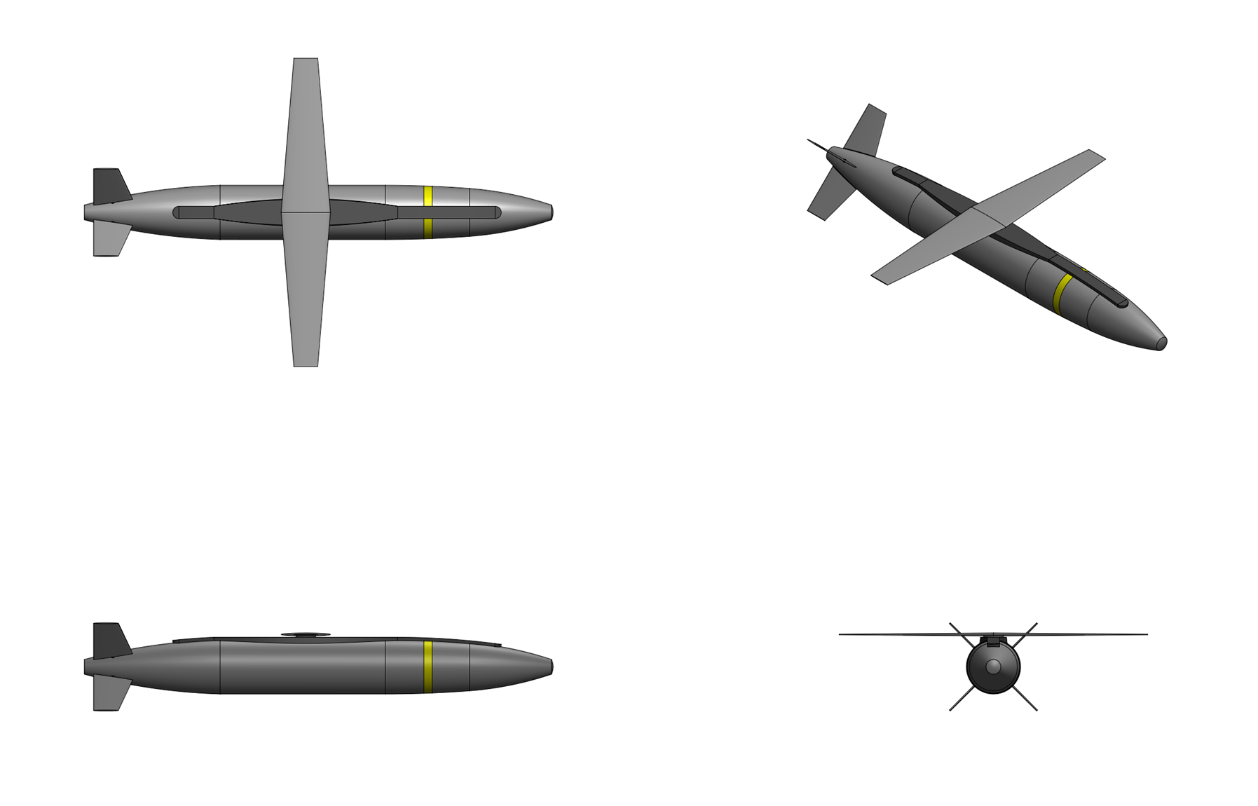
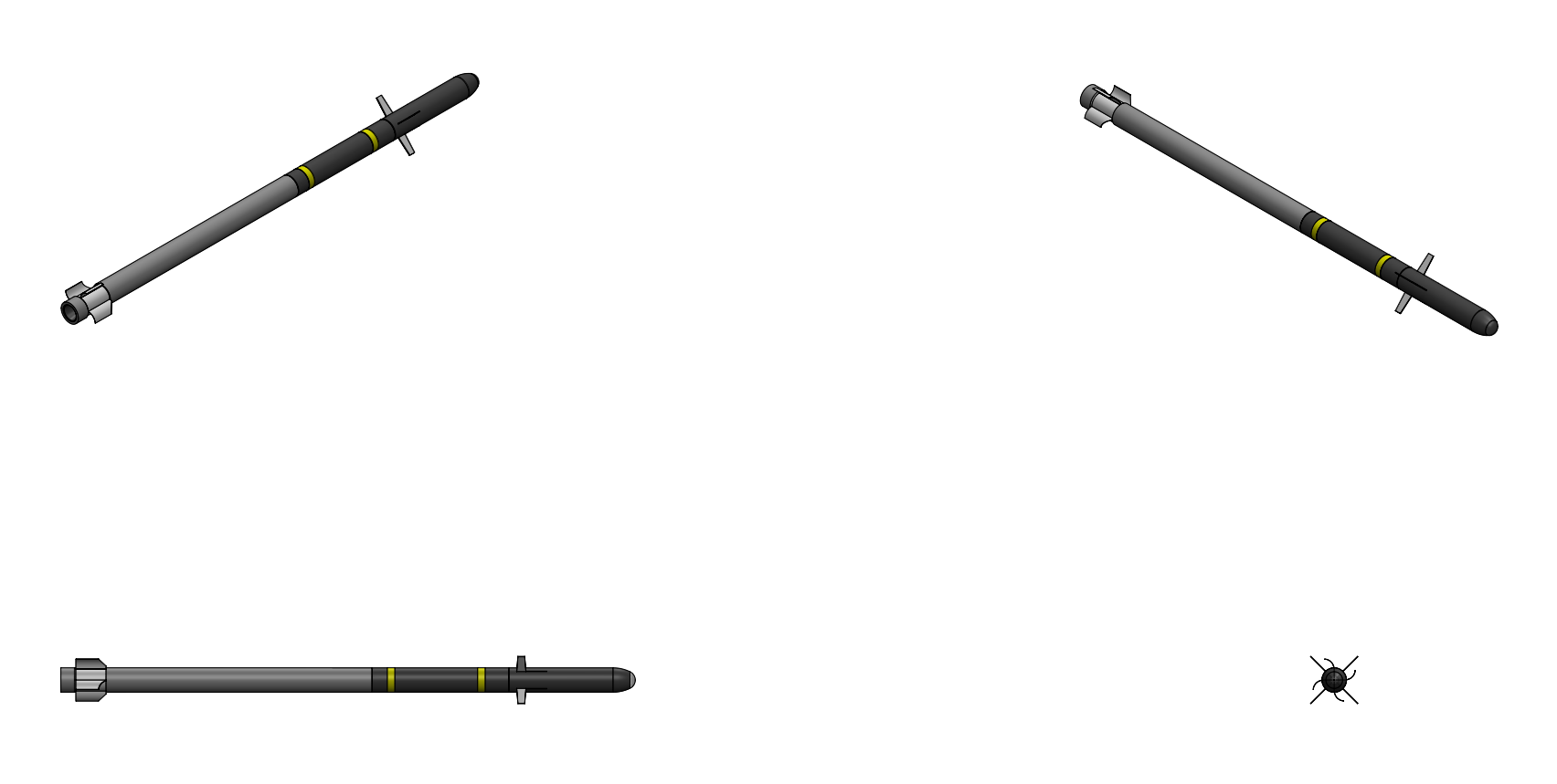
Rb 100 Wyvern


General Characteristics:
Type:
Long range air-to-air missile

Launch platform:
Aircraft

Guidance:
Tri-mode active RF/passive RF/IIR, INS/GPS, 2-way RF datalink

Physical Characteristics:
Weight:
250 kg

Length:
4.0 m

Diameter:
0.275 m

Warhead:
20 kg aimable reactive fragment

Performance Characteristics:
Propulsion:
Integral rocket-ramjer

Speed:
Mach 5.5

Maneuverability:
80 g

Altitude
0 to 35,000 meters

Range:
500 km (Mach 5.0 @ 25,000 m)


Overview:
The Rb 100 Wyvern is a long range, hypersonic anti-air and anti-radiation missile designed by SDI Missile Systems. The Wyvern integrates an Integrated Rocket-Ramjet (IRR) propulsion system combing an integral solid rocket booster and a thermally rhroated ramjet (TTRJ) hypersonic sustainer, a tri-mode terminal seeker combining active electronically scanned array (AESA) radar, passive radiofrequency homing, and imaging infrared sensing, a two way cooperative engagement datalink, a deformable warhead with reactive material fragments and guidance integrated fuzing, and bank-to-turn maneuvering enabled by the lifting body planform.


Airframe & Propulsion:
The Wyvern missile airframe consists of a tangent ogive nose cone, a cylindrical midbody, and a truncated conical boattail terminating in the integrated Aerofin/TVC nozzle assembly. A set of full length chines run continuously along the fuselage from the seeker section aft to the nozzle section, providing lift and reducing the fuselage radar cross section. At cruise anglse of attack the sharp chine leading edges generate vortices that produce strong vortex lift over the entire fuselage length that provides approximately 25% of additional body lift without any movable surfaces or additional actuators and further provide passive roll stability and yaw damping. The fuselage consists of five sections: the seeker section which contains the missile's tri mode seeker, the guidance section which contains the missile's guidance processor, INS/GPS unit, and thermal batteries, the warhead section which contains the missile's warhead and electronic safe and arm device (ESAD), propulsion section which contains the missile's integral rocket-ramjet engine, and control section which contains the missile's control actuation system and RF datalink antennas. The missile fuselage is constructed from Ti-6Al-4V/SiC metal matrix composite (MMC) consisting of silicon carbide fibers transversely wound into a Ti-6Al-4V titanium alloy matrix providing 50% higher specific strength than monolithic titanium at temperatures up to 350°C. To withstand sustained hypersonic heating the entire missile fuselage exterior is coated with a phenolic ablative thermal protection system (TPS) consisting of S-10 silicone reinforced phenolic applied as a bonded overlayer approximately 2.0 to 4.0 mm thick over the Ti-MMC primary structure. Embedded within the phenolic TPS matrix is a high temperature radar absorbing material (RAM) consisting of carbonyl iron and ferrite particles dispersed in the phenolic resin that provided broadband radar absorption across the X (8-12 GHz) through Ka (26-40 GHz) bands with typical reflectivity reduction of 10-15 dB at X-band and 8-12 dB at Ku-band, the RAM retains its absorptive properties at temperatures up to approximately 600°C. The The missile's radome is constructed from oxide ceramic matrix composite (CMC) construction that maintains both structural integrity and RF transparency at 600°C.

The Wyvern is powered by integral rocket ramjet propulsion system which combines a solid fuel rocket booster with a liquid fuel thermally throated ramjet (TTRJ) sustainer engine. The integral nozzleless solid rocket booster is packed inside the ramjet combustion chamber and consists of a center perforated star propellant grain containing 50 kg of SDI's 75% HNIW, 25% GAP high performance low observable propellant bonded to to the walls of the ramjet combustor. The booster burns for 4.5 seconds with a peak thrust of approximately 40 kN and accelerates the missile to a ramjet takeover speed of Mach 3.0. At the boost end Mach number of around 3.0 a pyrotechnic charge opens the inlet port cover, admitting supersonic airflow into the ramjet combustion chamber. The ramjet sustainer is a thermally throated ramjet that eliminates mechanically variable inlet and exhaust geometry of a conventional ramjet. The thermally throated ramjet controls the shock position by modulating the fuel flow rate, the fuel flow rate determining the heat release and backpressure in the combustion chamber. Increasing fuel flow moves the effective thermal throat upstream while decreasing fuel flow moves it downstream. The integrated fuel control system adjusts the fuel metering valve to maintain the desired shock position across the full Mach 3 to Mach 5.5 operating range, providing the equivalent of variable geometry performance with a fixed-geometry engine. The swept inlet is designed to produce a favorable spanwise pressure gradient that directs spilled air outboard and improves off design tolerance across the Mach 3 to Mach 5.5 operating range. The mixed compression design combines external oblique shocks with a final internal normal shock downstream of the cowl lip throat with a total pressure recovery ratio of approximately 0.50 at Mach 5. The inlet is fabricated from carbon/silicon carbide ceramic matrix composite. During the boost phase a conformal frangible cover seals the inlet and is jettisoned when the ramjet sustainer ignites. Fuel rich flameholding cavities and a piloted ignition system then initiate the ramjet combustion cycle. At booster burnout, pressure sensors in the combustion chamber detect the drop in chamber pressure below 1000 kPa, confirming complete propellant consumption. A gas generator then pressurize the inlet port cover ejection system, opening the inlet path. The fuel control valve opens then and endothermic fuel is injected into the flame holding cavities via a pilot fuel circuit and a pyrotechnic torch igniter initiates combustion in the flameholder region. The main fuel injectors are then activated and the ramjet reaches steady state combustion. The missile then continues accelerating to the design Mach 5.0 cruise speed at 25,000 meters altitude.

The missile uses a endothermic J9 high-density synthetic jet fuel. When heated above 315°C in the presence of a platinum-alumina catalyst liner integrated into a set of catalytic heat exchanger reactors in the the fuel delivery circuit J9 undergoes exothermic decomposition to toluene and hydrogen gas, the endothermic reaction absorbing approximately 2,500 kj/kg of heat, providing a substantial thermal sink for regenerative cooling of the combustion chamber walls, and nozzle throat region, enabling sustained Mach 5 flight within the thermal constraints of the lightweight missile airframe. The ramjet combustor and nozzle are constructed from 3-D carbon-carbon (C-C) ceramic matrix composite with outer tape wrapped silica phenolic insulation and an inner zirconia-based (ZrO₂) thermal barrier coating. Additional passive alumina blanket insulation is applied between the warhead section and the combustion chamber to thermally isolate the explosive fill from propulsion system heat. The fuel tank for the ramjet is located ahead of the ramjet combustor contains 50 kg of fuel which is fed into the ramjet combustor using a turbopump propellant feed system. The fuel within the tank serves as a thermal heat sink with the regenerative cooling circuit routing fuel through the highest temperature zones before delivery to the combustion chamber. The tank is sealed with elastomeric bladders that maintain positive fuel head under all flight accelerations. The fuel system uses a turbine driven fuel pump powered by a small bleed air turbine using air tapped from the inlet duct that drives a positive-displacement gear pump that pressurizes the fuel to 5.0 to 8.0 MPa injection pressure and delivers it through the fuel cooling circuit into the combustion chamber. From the fuel tank the fuel first passes through a catalytic heat exchanger jacket surrounding the combustion chamber outer wall where it absorbs conducted heat while undergoing endothermic decomposition. The preheated partially decomposed fuel (now a mixture of toluene, hydrogen, and unreacted heavier hydrocarbons at approximately 350°C) is then injected into the engine. The hydrogen rich fraction of the decomposed fuel enhances combustion kinetics and flame stability while the heat absorbed during dehydrogenation keeps the combustion chamber wall temperature within limits. The ramjet combustor is designed for a 1,950°C operating temperature and provides for a nominal specific impulse of 1,800 seconds at cruise conditions. The fuel management system (FMS) operates pneumatically using air bled from the inlet duct as an airflow reference and is controlled by signals from the missile autopilot to vary the fuel-to-air ratio of the ramjet for ramjet speed control during flight. The fuel control system receives inputs from inlet pressure sensors, combustion chamber pressure and temperature sensors, nozzle throat temperature sensors and the missile air data system. The FCS computes the required fuel flow rate to maintain the desired thrust while keeping the thermal throat position within stable limit and modulates a fuel metering valve downstream of the pump. The FCS also manages the fuel cooling circuit routing and monitors fuel temperature at the cooling circuit exit to prevent exceeding the J9 thermal stability limit. The fuel mass of approximately 50 kg producing a burn time of approximately 150 seconds at cruise fuel flow rate with an endgame fuel reserve of approximately 6.5 kg providing 12 to 18 seconds of maximum thrust terminal maneuvering.

The motor nozzle is made from 4D woven carbon-carbon (C/C) composite with a titanium nozzle shell and aft enclosure which also serves to mount the missile's aerodynamic steering fins and electro hydraulic actuators. The missile aft control fins are fabricated from C/SiC ceramic matrix composite and driven by miniature electro-hydraulic actuators rated for deflection rates exceeding 200°/s and maximum deflections of ±25°. Four cruciform C/SiC nozzle vane extensions simultaneously serve as exhaust jet deflection vanes when the rocket booster and TTRJ are operating, the integrated Aerofin/TVC system maintaining control authority at high altitude and low dynamic pressure conditions where purely aerodynamic fins would be insufficient and providing enhanced terminal maneuvering capability during the endgame phase, providing approximately 15 g of additional maneuvering authority during powered flight. The ramjet engine lifting-body planform of the missile naturally lends itself to bank-to-turn (BTT) maneuvering rather than the skid-to-turn (STT) approach used by most air-to-air missiles. Pitch and yaw control is provided by four all moving folding tail control surfaces which are actuated by high-torque electro-hydraulic actuators inside the missile's tail control sectiom. The thrust vector control system provides additional pitch and yaw authority during powered flight phases. The flight control system implements a blended BTT/STT control law, defaulting to pure BTT during cruise which aligns the lift vector with the desired maneuver plane before pulling angle of attack. BTT is preferred during cruise as the ventral inlet performs optimally at positive angles of attack and BTT avoids the large sideslip angles that would degrade inlet performance. In the terminal endgame phase, the final 3 to 5 seconds before intercept, the flight control transitions to skid to turn (STT) maneuvering, generating lateral acceleration directly through combined pitch and yaw commands without first rolling. The Aerofin/TVC system provides the combined control forces needed for high-g STT endgame maneuver with the TVC component generating yaw forces without the inlet disrupting sideslip of purely aerodynamic yaw control. The control law transitions are managed by a gain scheduled adaptive autopilot that accounts for the highly nonlinear aerodynamics of the lifting body shape across the flight envelope from subsonic launch conditions through hypersonic terminal intercept.


Guidance & Navigation:
The Wyvern uses a SDI designed dual-aperture tri-mode seeker unit which combines an active Ka band (35 GHz) radar seeker, wide-band (0.5 - 40 GHz) passive radar seeker, and a mid-wave imaging infrared seeker. After being fired by the launching aircraft in the general direction of the target the missile uses the passive radar seeker to silently search for and home in on the target's radar or radio emissions. If no emissions are detected the missile is programmed to briefly switch on its own radar seeker and conduct a search for a target. If a target is found another short active radar sweep is done a few seconds later to get speed and heading information and to confirm the target's identity through the automatic target recognition (ATR) functionality of the radar seeker. The missile then flies to the computed kill zone where it then homes in the target using sensor fusion of the IIR and active radar seeker, the use of both radar and imaging infrared imaging for terminal being intended to make the missile extremely resilient to electronic countermeasures and active decoys deployed by the target. Midcourse guidance is provided by a 6-axis SDI TNS 450 tactical-grade timing and inertial measurement Unit (TIMU) which combines three milli-Hemispherical Resonator Gyroscope (mHRG) and three quartz resonating beam accelerometers (RBA) in a low SWaP package (500 cc volume, <1.0 kg mass, <5 watts max power consumption) package which provides <0.0003°/√hr gyro angle random walk and < 0.0001 °/hr bias stability performance. The IMU is coupled to an SDI designed GPS spatial temporal anti-jam receiver (GSTAR) unit with wide area differential GPS (WADGPS) capability providing <1 meter resolution 3-dimensional position accuracy in flight. A 2-way RF datalink operating in the Ku band is also fitted to the missile which allows guidance updates from the launch aircraft to be sent to the missile and flight and for weapon impact assessment (WIA) information including real time missile status, location and target information to be sent back to the launch aircraft in flight.

The radar seeker consists of a Ka band (35 GHz) active electronically-scanned array (AESA) seeker assembly which is housed in a broadband ceramic radome constructed of reaction-sintered silicon nitride (Si3N4). The Ka band seeker employs a digital beamformer, digital MEMS phase shifters, and a planar array of GaN (Gallium Nitride) on diamond monolithic microwave integrated circuit (MMIC) T/R modules and power amplifiers and is capable of scanning +/- 60° off boresight in both azimuth and elevation. The millimeter-wave Ka band seeker provides an extremely high angular resolution for target tracking and discrimination and features over 1 GHz of instantaneous bandwidth for increased ECM resistance. The use of a digital beamformer also enables the use of adaptive beamforming which along with super resolution algorithms enables the seeker to accurately recognize, locate, and suppress jammer sources while performing target acquisition and tracking tasks. ECCM features of the seeker include frequency-modulated continuous-wave (FMCW) operation to minimize probability of detection by enemy receivers, high instantaneous bandwidth, dual-polarized aperture, randomized burst transmissions, active sidelobe cancellation, and home-on-jam (HOJ) functionality. The radar supports multiple simultaneous waveforms including narrow-beam, high-PRF search mode for initial acquisition; a medium-PRF track-while-scan mode for maintaining awareness of multiple targets in a group engagement; and a monopulse tracking mode with leading-edge range gating for precision terminal guidance against low-RCS targets in clutter. The array’s electronic beam steering permits rapid search of the predicted target basket and supports home-on-jam functionality by measuring the angle-of-arrival of hostile jamming signals. Towed RF decoys are countered by the seeker’s monopulse angle tracking and range resolved waveform, which can separate the tow body from the parent aircraft in both angle and range. The seeker's onboard automatic target recognition processor classifies targets by type using a neural network classifier that compares measured HRR profiles against a stored library of reference signatures. Target classes include fighter aircraft, bomber aircraft, cruise missiles, unmanned aerial vehicles and various decoy types. The HRR ATR capability is effective against towed decoys, expendable decoys and cooperative countermeasures as the range resolved signatures of these objects differ from intended targets. The radar also provides aimpoint selection by identifying specific structural features for optimized warhead detonation geometry. The passive seeker assembly consists of of a total of 12 conformal, ultra-wideband antennas placed radially around the missiles forward fuselage behind the radar seeker assembly which provide detection of radar signals in the 500 MHz to 40 GHz range (UHF - Ka Band), enabling the missile to home passively on emissions from the target’s own radar, datalinks, jamming transmissions, or electronic warfare systems. The 12 antennas feed into a photonic receiver unit with >40 GHz of instantaneous bandwidth and provides accurate detection, classification, and angle of arrival (AoA) information of incident radar waves and allows the missile to passively home in on emitting aircraft or ground based radars without the use of its active radar seeker. The seeker incorporates an emitter classification library that identifies threat radar types by pulse repetition interval, pulse width, frequency and scan pattern. The passive seeker serves as the primary sensor for the anti-radiation missile mode and maintains track files on detected emitters including those that have ceased transmitting using last-known position and predicted behavior. When used as an anti-radiation missile the missile can operate in four modes; direct mode, area suppression mode, or self-protect mode. In direct mode, which is primarily intended for attacking stationary emitters, the missile is launched an emitter with a known range and bearing where the missile flies a minimum time-of-flight trajectory to engage the target in as short a time as is possible. In area suppression mode, which is intended for attacking mobile SAM systems, maritime targets, and AEW aircraft, the missile is programmed to fly toward a specific area at high altitudes and then dive towards the target area while searching for a specific target or targets programmed before launch. In self protect or reactive mode, which is intended to engage pop-up emitters at short to medium ranges in a 360° aspect around the aircraft, the missile is launched towards a target detected by the aircraft's RWR/ECM system and after launch will immediately turn and fly directly towards the target emitter bearing until the missile is able to acquire it with its own seeker.

The imaging infrared (IIR) seeker is mounted behind and below the main RF radome viewing through its own dedicated faceted infrared window. The infrared seeker assembly consists of a 640 x 512 pixel imaging infrared (IIR) seeker mounted on a 2-axis gimbal i for pointing and stabilization which provides the seeker with +/- 90 degree field of view capability. The IIR seeker employs an InGaAs (indium gallium arsenide) nBn type high-operating-temperature (HOT) staring focal plane array (FPA) detector array which operates in the MWIR (3-5 µm) band. A micro-Integrated dewar cooler assembly with miniature Stirling-cycle cryocooler is used to keep the high-operating-temperature (HOT) detector at a temperature of 120K, higher than the 77K required of traditional cooled IR detectors and reducing the sight, weight, and power consumption of the cooling unit. The infrared seeker is mounted behind diamond coated silicon windows with internal cooling passages used to circulate a 50/50 ethylene glycol (EG) water coolant. Coolant is circulated through the internal passages by a small electric pump, absorbing aerodynamic heating from the window surface and rejecting the heat overboard through an expulsion port. The chemical vapor deposited (CVD) polycrystalline diamond coating (approximately 0.5 mm thick) provides exceptional broadband IR transparency (transmittance > 70% at 3-5 μm), extreme hardness for rain and particle erosion resistance, and thermal conductivity approximately 5× higher than silicon. The water cooling system carries approximately 0.75 kg of distilled water in a small pressurized reservoi providing approximately 45 seconds of active window cooling at the design heat flux. Coolant is expelled overboard after absorbing thermal energy. The cooling system activates upon TTRJ ignition at Mach 3 when aerodynamic heating on the window becomes significant, maintaining the IIR window temperature below 400 K throughout hypersonic cruise and ensuring the MCT focal plane array receives undistorted IR imagery, necessary for IIR operation at sustained Mach 5 soeeds where uncooled windows would reach temperatures exceeding 900 K, rendering them opaque in the MWIR band and degrading focal plane array performance. The IIR seeker employs onboard automatic target recognition (ATR) algorithms running on the guidance processor’s embedded neural processing unit (NPU) which classify target type, distinguish between aircraft and decoy flares, and select optimal aimpoints on the target airframe. The ATR is trained on a library of threat aircraft infrared signatures across multiple aspect angles and atmospheric conditions. During IIR seeker homing the missile is programmed to maintain a positive angle-of-attack and a positive attitude relative to the target to ensure it stays within the FOV of the infrared seeker.

The three seeker systems of the missile are fused at the track level within the guidance processor, a system-on-chip (SoC) combining a multi-core CPU with a dedicated SDI Lattice neural processing unit. The guidance processor fuses the target classifications from the HRR radar ATR and the IIR ATR into a single assessment using a Bayesian classifier that combines the independent probability assessments from each sensor. A countermeasure that is effective against the system must simultaneously replicate both the radar scattering profile and the thermal signature of the intended target. The system operates in three modes. In classification mode it identifies the target type, in discrimination mode it distinguishes targets from decoys and countermeasures, and in aimpoint mode it fuses the HRR structural mapping and the IIR thermal mapping to determine the optimal impact point for warhead effectiveness. The fusion algorithm maintains a unified target state estimate (position, velocity, acceleration) by weighting inputs from each sensor mode according to its current signal-to-noise ratio and measurement quality that allows seamless handoff between modes: for example, the missile might begin terminal homing in active radar mode, transition to passive RF if the target activates its jammer, and further transition to combined RF/IIR for the final seconds of flight as range closes and the target thermal signature becomes unambiguous. Terminal guidance employs an augmented proportional navigation (APN) law with impact-time control capability which shapes the intercept trajectory to minimize time-to-go estimation errors and to bias the missile toward a predicted aimpoint on the target rather than the target centroid. In the final seconds before intercept the guidance law transitions to a line-of-sight rate nulling mode optimized for endgame accuracy against a maneuvering target, also shifting missile control to pure skit-to-turn (STT) mode for enhanced terminal maneuverability.

The Wyvern missile also incorporates a two-way, jam-resistant datalink operating in a frequency-hopping spread-spectrum mode within the Ku (12 - 18 GHz) band. The Ku band support high data rates from 64 kbps to 45 Mbps, are required for real time transmission of compressed seeker imagery during terminal engagement and Weapons Impact Assessment while the smaller antenna apertures at Ku-band frequencies allow conformal integration into the missile body. Uplink (launch aircraft-to-missile) functions include transmitting mid-course guidance updates including target position refinements from the launch aircraft's sensors cueing from offboard sensors (AEW, other fighters, space-based assets), and re-targeting commands. This allows the missile to fly an energy-optimized lofted trajectory during mid-course flight, correcting for target maneuvers that occur during the long time of flight, and even redirecting to a different target in flight. Downlink (missile-to-launch-aircraft) communications include missile state data (position, velocity, remaining energy, seeker status) and seeker imagery and track data from the missile’s own sensors back to the launch aircraft. The transceiver implements an ATDL mesh waveform which supports distributed mesh networking with up to 32 nodes with tiered networks extending beyond 32 nodes. The network latency is less than 64 ms across the entire swarm. The transceiver provides AES-256 level encryption for communication security while in-band jammer and interference sensing with automatic frequency agility provides anti-jam capability. The conformal Ku-band antennas are integrated into the missile body surface aft of the chine region. The transceiver mass is approximately 0.5 kg and power consumption is approximately 30 W. The Ku-band dat link enables collaborative swarming engagements in which multiple Wyvern missiles communicate with each other and with the launching aircraft. Cooperative target assignment prevents wasteful multiple engagements of the same target while ensuring that no target in a group is left unengaged, cooperative geometry optimization coordinates missiles to arrive from different threat axes simultaneously. Missile-to-missile target handoff allows a missile that has classified a target via ATR to pass that classification and track to other missiles in the swarm. Cooperative emitter geolocation uses bearing measurements from multiple missiles at different positions to triangulate emitter positions with precision that exceeds what a single missile can achieve. The launching aircraft transmits midcourse guidance updates, revised target coordinates, retargeting commands and abort commands. The missile transmits health and status data, seeker acquisition reports, ATR classification results and WIA terminal imagery. The data link supports coordination between multiple salvos launched from different aircraft. The Weapons Impact Assessment / Battle Damage Indication (WIA/BDI) function operates as a high-priority burst transmission within the mesh protocol and transmits terminal seeker imagery captured immediately before and at the moment of warhead detonation back to the launching aircraft via the Ku band channel. The transmitted data consists of 2 to 4 compressed IIR image frames at 640 by 512 pixel resolution with lossy compression to approximately 50 to 100 KB per frame along with the final HRR radar range profile. These data are buffered in solid state memory and transmitted in the final seconds before impact. If the missile executes a reattack maneuver the WIA system captures imagery from both the initial miss event and the second approach. The WIS capability allows the pilot to observe the terminal engagement and confirm target destruction. The downlink also supports cooperative engagement concepts where the missile’s seeker acts as a forward sensor node for the broader combat network. The antenna’s pattern is shaped to maintain connectivity across a wide range of missile-to-shooter geometries with a reliable communication out to 500 km in heavy jamming environments.


Warhead & Fuzing:
The Wyvern features an advanced directional warhead design that allow it to be asymmetrically detonated, directing the majority of the fragment spray into a focused cone oriented toward the predicted target location at the moment of detonation rather than distributing fragments uniformly in an annular pattern. The warhead consists of a pre fragmented cylinder constructed from approximately 2,400 3.5 mm reactive tungsten shrapnel cubes surrounding a cylindrical polymer-bonded explosive (92% HNIW, 4.8% BDNPA/F, 3.2% CAB) charge. The prefragmented cylinder is surrounded by twelve radial strips of additional PBX which can each be independently detonated. When the warhead is fuzed the charges facing the strips on the side facing the target are detonated, causes the pre-fragmented case to flatten in the direction of the target. The main charge inside the case and the line charges on the opposite side of the target direction are then detonated, causing the fragments in the flattened part of the case to be ejected in the direction of the target at extremely high velocity. The reactive shrapnel is made from a sintered PTFE/Aluminum/Nickel mixture (11.5% Al, 71.5% Ni, 17% PTFE) which is inert under normal conditions but unlike regular shrapnel will explode and burn when subjected to the stress of hypervelocity impact with a solid object. Upon impact with the target structure at hypersonic velocity, these fragments undergo a violent exothermic intermetallic reaction upon penetration, releasing approximately three to five times the energy of their equivalent mass of TNT, generating intense thermal and blast overpressure effects inside the target airframe’s internal structure, dramatically increasing the probability of igniting fuel, detonating onboard munitions, severing hydraulic lines, and destroying avionics. Against modern composite-skinned aircraft, where conventional kinetic fragments can pass cleanly through without causing catastrophic structural damage, the reactive material fragments’ internal energy release provides a far more lethal damage mechanism.

Detonation of the warhead is controlled by a guidance integrated fuzing (GIF) system which uses target angle and velocity measurements from the missile's radar seeker and imaging infrared seeker to adaptively fuze the warhead. High resolution target range and bearing information from the radar seeker and bearing information from the infrared seeker is used to provide real-time predictions of time and position of target intercept in the warhead plane in order to compute optimum warhead initiation time to minimize miss distance. Inputs to the guidance integrated fuzing algorithm include the seeker’s last-measured line-of-sight rate; the time-to-intercept estimate from the guidance law; accelerometer-derived closing velocity; and if available a final target range measurement from the Ka-band seeker operating in a dedicated high-bandwidth ranging mode during the last several hundred milliseconds of flight. The guidance integrated fuzing algorithm computes the three-dimensional miss vector, commands the warhead detonators to orient the fragment cone, and fires the detonation train at the instant that maximizes fragment density on the target. For direct-hit scenarios at hypersonic closing velocities, the fuze also supports contact detonation via crush switches in the nose section, which trigger the warhead after penetration of the target skin to detonate inside the airframe for maximum destructive effect. A set of selectable fuzing modes allows the guidance computer to adapt between proximity-optimized and hit-to-kill-optimized fuzing logic depending on the engagement geometry and target class.


Flight Sequence:
For air-to-air engagements the missile flight sequence proceeds in four phases. The missile is ejected from the launch rail or weapons bay and the CL-20/GAP booster ignites, accelerating the missile to Mach 3.0 in approximately 4.5 seconds covering approximately 4 nautical miles. The mHRG IMU maintains the intercept heading while midcourse corrections are received via the Ku band data link. Flight control operates in bank-to-turn mode from launch. The inlet cover is jettisoned at Mach 3 and the ramjet sustainer then ignites. The missile accelerates to Mach 5.0 and climbs to 25,000 meters. The IIR window cooling system activates at Mach 5.0 while the passive RF seeker searches continuously for target emissions. The data link provides midcourse updates from the launch aircraft or from other missiles in the swarm as missiles share target track data and coordinate approach geometries. At approximately 30 to 50 nautical miles from the predicted target position the GaN Ka-band AESA radar activates and executes search sweeps. The endgame fuel reserve valve opens. Upon target detection the HRR ATR system begins building a target classification using 2 to 4 radar sweeps over 3 to 8 seconds. The ATR validates the target against preloaded engagement rules. Within the final 10 to 15 nautical miles both the radar and the IIR seeker operate simultaneously for dual mode terminal guidance with dual mode ATR fusion. The guidance law transitions from proportional navigation to optimized terminal guidance. In the final 3 to 5 seconds the autopilot transitions from bank-to-turn to skid-to-turn for maximum endgame agility as the ramjet operates on reserve fuel at elevated thrust. The adaptive proximity fuze function arms and the selectively aimable warhead receives the predicted target bearing for initiation point selection. If a miss is detected the guidance processor initiates a pull-up and reacquisition maneuver using remaining reserve fuel. The reattack envelope extends to approximately 5 nautical miles from the missed intercept point. The WIA data link transmits terminal seeker imagery to the launching aircraft.

In the anti-radiation role the missile engages ground based radar emitters. Prior to launch the aircraft electronic warfare and ELINT systems provide emitter type, location, frequency and pulse characteristics. The launch, boost and cruise phases are identical to the air-to-air profile. During cruise the passive RF seeker homes on the emitter emissions. When multiple networked missiles detect the same emitter from different positions the cooperative geolocation function triangulates the emitter position with higher accuracy than a single missile bearing only estimate. If the emitter ceases transmitting the missile continues to the last known position using the mHRG IMU. The low drift rate of the mHRG ensures that the navigation error accumulated during coast to a silent emitter remains within the acquisition basket of the active sensors. In the terminal phase the GaN AESA radar and IIR seeker activate to acquire the emitter platform. The dual mode ATR identifies the platform type and selects the optimal aimpoint. The missile executes a steep terminal dive transitioning to skid-to-turn for maximum accuracy. The WIA data link transmits terminal imagery to confirm target destruction.
Last edited by The Technocratic Syndicalists on Tue Sep 01, 2026 6:52 pm, edited 59 times in total.
SDI AG
Arcaenian Military Factbook
Task Force Atlas
International Freedom Coalition


OOC: Call me Techno for Short
IC: The Kingdom of Arcaenia

User avatar
The Technocratic Syndicalists
Minister
 
Posts: 2350
Founded: May 27, 2015
Inoffensive Centrist Democracy

Postby The Technocratic Syndicalists » Mon Jan 30, 2017 9:34 pm

Image


RBS 83 Arbalest


General Characteristics:
Type:
Stealth Cruise Missile

Launch platform:
VLS

Guidance:
INS/GPS, PTAN, IIR

Physical Characteristics:
Weight:
1,750 kg (missile), 2,150 kg (with booster)

Length:
6.3 m (missile), 7.0 m (with booster)

Diameter:
0.6 m

Warhead:
480 kg multi-mode tandem charge warhead


Performance Characteristics:
Propulsion:
Propfan

Speed:
Mach 0.85

Range:
3,700 km


Overview:
The RBS 83 Arbalest is an ultra-long range, surface launched, low-observable subsonic cruise missile designed by SDI Missile Systems. The RBS 83 is intended for precision strikes on high value targets including airfields, radar stations, and hardened and deeply buried targets and consists of a low observable airframe, propfan propulsion system, INS/GPS, terrain reference, and image based navigation system, and a tandem warhead system capable of defeating both hardened fixed and area targets.


Airframe
The RBS 83 missile employs a faceted six-sided hexagonal composite fuselage housing the guidance and navigation section in the forward bay, the warhead at the center of gravity, integral fuel tanks fore and aft of the warhead section, and the propulsion system at the aft end. A single oblique win mounted on a pivot mechanism at approximately the 50% fuselage station deploys after launch and rotates to the optimum sweep angle during cruise flight. Four folding control fins are arranged in an X-pattern immediately forward of the propfan blades, providing pitch, yaw, and roll authority throughout the flight envelope. The faceted body shape maximizes internal volume within the cylindrical launcher envelope while providing flat panel surfaces that reduce specular radar returns from off-axis illumination angles. The primary structure is fabricated from vacuum assisted resin transfer molding (VARTM) formed carbon fiber reinforced polymer (CFRP) composite with a co-cured radar-absorbing structure (RAS with lossy dielectric layers directly into the composite laminate stackup. The outer mold line panels of the fuselage, wing, and control surfaces serve simultaneously as structural skins and as broadband radar absorbers providing low-observable performance without a parasitic weight penalty. Metallic component including the wing pivot mechanism, engine mounts, and selected structural fittings are fabricated from titanium alloy to minimize both weight and galvanic corrosion risk at composite-metal interfaces. Edge treatments are employed on all panel joints, access doors, and the wing pivot fairing employ serrated or saw-tooth geometries to scatter edge diffraction returns away from the threat radar line of sight. The engine air intake incorporates a low-observable inlet design with a serpentine duct that eliminates direct line-of-sight to the engine compressor face, removing the dominant contributor to the frontal RCS of conventional cruise missiles. The propfan blades employ composite blade construction with embedded RAM layers. When viewed from the front aspect at X band frequencies the airframe achieves an RCS on the order of 0.005 to 0.01 square meters.

The oblique wing is a single continuous wing panel mounted on a centrally located pivot that allows it to rotate from a perpendicular unswept orientation for low-speed flight to a swept orientation for high subsonic cruise. The oblique wing oblique wing stows flush against the upper fuselage and rotates as a single structural element about a central pivot with both tips sweeping aft along the fuselage, leaving substantially more internal volume available for fuel and directly contributing to increased range. the oblique wing configuration permits the warhead to be located precisely at the vehicle center of gravity directly beneath the wing pivot. In a conventional wing arrangement, the wing carry-through structure occupies the center fuselage and forces the warhead to be placed either forward or aft, creating asymmetric mass distribution that complicates center-of-gravity management as fuel is consumed during flight. The oblique wing pivot occupies a minimal cross-sectional area, allowing the warhead bay and the wing pivot to coexist at the same fuselage station. The oblique wing also provides continuously variable sweep allowing the flight control system to optimize the wing sweep angle for each phase of flight. At low speed and during the initial climb after booster separation, the wing is oriented at low sweep of approximately 25° to provide maximum lift and minimum induced drag. As the vehicle accelerates and climbs to its high-altitude cruise condition, the wing sweeps progressively to approximately 55 to 60°, delaying the onset of transonic drag rise and allowing efficient cruise at Mach 0.70 to 0.80. During terminal descent and maneuvering, the wing can be returned to a lower sweep angle to increase lift capability and tighten the turning radius. The wing structure employs aeroelastic tailoring of the composite laminate selecting fiber orientations such that the wing twists slightly as it bends, partially offsetting the adverse angle-of-attack change. The tailoring is optimized for the design cruise sweep angle of 55°and remains effective over the operational sweep range of 25 to 65°. The forward and aft panels of the oblique wing have different span and taper ratios to achieve a near-constant section lift coefficient across the span while simultaneously approaching an elliptic span load distribution for minimum induced drag. Specially developed airfoil section shapes, tailored for each spanwise station provide high maximum lift capability for terminal maneuvering while maintaining low profile drag at the design cruise lift coefficient.


Propulsion
  • Name: SDI TPM360
  • Type: Three-shaft Propfan
  • Length: 750 mm
  • Diameter: 300 mm
  • Dry Weight: 65 kg
  • Bypass ratio: 35:1
  • Compressor: 1 stage axial LPC, 1 stage axial IPT, 1 stage centrifugal HPC
  • Combustor: Annular combustor
  • Turbine: 1 stage radial HPT, 1 stage radial IPT, 3 stage LPT
  • Maximum Thrust: 5.0 kN
  • Overall pressure ratio: 45:1
  • Specific fuel consumption: 10 g/Kn-s
  • Turbine inlet temperature: 1,430 °C
  • Thrust-to-Weight Ratio: 8.0:1
The RBS 93 missile is powered by an SDI TPM360 propfan engine which produces up to 5 kN of thrust. The TPM is a three-spool counter rotating propfan engine that drives the aft mounted propfan rotors through an epicyclic gear reduction unit. The compressor comprises three compressor stages distributed across the three spools. The low-pressure compressor (LPC) consists of a single axial stage operating at a pressure ratio of approximately 1.65:1 that provides the initial compression with low losses and feeds the intermediate-pressure compressor (IPC). The IPC is a compound stage consisting of one axial stage followed by one centrifugal stage ,producing a combined pressure ratio of approximately 4.4:1. The high-pressure compressor (HPC) is a single centrifugal stage with a pressure ratio of approximately 3.95:1. In the front end of the engine, carbon/polymide composites are used extensively for the inlet duct, front frame, LP compressor stators, and compressor housings, operating at temperatures up to 430°C. These polymer composite components are manufactured by filament winding or injection/transfer molding, providing low cost and light weight. The LP compressor rotor blades are fabricated from carbon/polymide composite, which provides the required strength at the LPC operating temperatures (below 315°C / 600°F) while allowing tip speed increases of 40 to 80& over metallic rotors. The IPC and HPC rotors employ advanced titanium aluminide alloys produced by rapid solidification powder metallurgy and hot isostatic pressing, providing the creep/rupture capability and bore temperature tolerance necessary at the higher compressor discharge temperatures.

The engine employs an annular slinger combustor with centrifugal fuel injection. The slinger combustor distributes J9 fuecentrifugally from a rotating cup at the compressor discharge, producing fine atomization without the complexity and cost of conventional pressure-atomizing fuel nozzles. The combustor liner is fabricated from carbon/carbon composite material with a high-temperature oxidation coatin, enabling uncooled or minimally cooled operation at gas temperatures up to 1600°C. The combustor residence time of 5.2 to 14.8 milliseconds provides wide operational margin for stable combustion across the flight envelope. The high-pressure turbine (HPT) is a single-stage radial inflow turbine fabricated from silicon carbide/silicon carbide (SiC/SiC) ceramic matrix composite (CMC). The uncooled CMC radial HPT eliminates blade cooling passages, reduces part count, and dramatically simplifies the HP turbine module relative to a cooled metallic design. The intermediate pressure turbine (IPT) is another single-stage radial inflow turbine of ceramic SiC/SiC composite construction, operating at the lower gas temperature downstream of the HPT. The IPT drives the IPC through the intermediate shaft. The low-pressure turbine (LPT) is a three-stage axial turbine driving the LPC and through the epicyclic reduction gearbox the counter-rotating propfan. The LPT operates at the lowest gas temperatures in the turbine section and is fabricated from Gamma titanium aluminide (γ-TiAl) integral bladed rotors. The three-stage axial LPT configuration provides the high work extraction and low exit swirl necessary to deliver efficient power to the propfan through the reduction gearbox. In the hot section of the engine ceramic composites and carbon/carbon are sued extensively. .The combustor liner, turbine inlet nozzles, and exhaust duct are fabricated from carbon/carbon with high-temperature oxidation coatings, operating uncooled at temperatures up to 1760°C. The turbine nozzle guide vanes are SiC/SiC CMC, also operating uncooled.

The propfan reduction gearbox is an epicyclic planetary design that converts the high-speed LPT output shaft rotation to the lower speed required by the counter-rotating propfan. The counter-rotating output drives the 8×8 bladed propfan through concentric shafts with the forward and aft blade rows rotating in opposite directions to recover swirl losses and maximize propulsive efficiency. The missilized gearbox design incorporates a self-contained lubrication system that eliminates the conventional oil tank, heat exchanger, and oil conditioning equipment, reducing weight and volume at the expense of requiring Silicon and fluorosilicone synthetic oils with a higher thermal stability and favorable viscosity-temperature relationship.
The gearbox employs hybrid ceramic/metallic cermet rolling element bearings on the HP and IP spools, combining silicon nitride (Si₃N₄) rolling elements with advanced carburized metallic races. The hybrid bearings provide three to five times the rolling contact fatigue life of conventional metallic bearings and operate at temperatures 200°C above the metallic bearing limits. For sealing the gearbox employs non-contacting hydrodynamic/hydrostatic seals at the high speed locations, operating at surface velocities up to 275 M/sec and temperatures to 650°C. The propfan rotor employs an 8x8 fan blade arrangement with two rows of 8 thin, highly swept propeller blades made from 4D wound carbon fiber/epoxy composite. The propfan blades are hinged and actuated at their base, allowing them to fold for storage inside the missile launch canister. The blade pitch actuation mechanism is a lightweight hydraulic system integrated into the propfan hub with a fail-safe pitch lock at the cruise design point. Each propfan blade is an entirely composite (carbon fiber/epoxy) structure designed for minimal radar cross section with embedded radar-absorbing material in the blade leading edge and tip regions. The blades fold aft against the fuselage for stowage within the Mk 41 VLS canister and deploy via spring-loaded hinges with pyrotechnic release after booster separation. The engine is fed by a flush-mounted, low-observable air intake located on the lower surface of the aft fuselage that eliminates the drag and RCS penalties associated with a protruding pitot intake while accepting a slight reduction in pressure recovery at high angles of attack. A serpentine inlet duct routes airflow from the flush aperture to the compressor face through two approximately 45 ° bends, ensuring that no direct line-of-sight exists between the external inlet opening and the engine compressor. The duct walls are treated with a broadband radar-absorbing liner that attenuates any residual radar energy entering the inlet. The propfan blades are mounted on a hub at the aft end of the fuselage and the exhaust gases from the core engine exit through a central annular nozzle surrounded by the propfan disk.

The TPM360 includes a dual-channel full authority digital electronic control system (FADEC) with control modes including independent control of blade pitch and propeller speed allowing variable synchrophasing control of each propfan engine to minimize engine noise and vibration, protective measures for regulating turbine-inlet temperature and preventing inadvertent engine overspeed or overtorque, and fault modes allowing for propellor blade feathering and gas generator compressor/turbine section windmilling if an engine fails or has to be shut down in flight. The FADEC control system is housed in a dual-channel electronic control unit containing circuitry connected to various engine sensors whose inputs are used by the FADEC system to control fuel flow, propeller pitch, variable compressor vanes and stators, bleed air flow, and other systems to optimize the performance of the engine throughout the missile's flight envelope.

The aft end of the missile mates to a jettison able solid propellant rocket booster that accelerates the vehicle to the propfan self sustaining flight speed and transitions it from the vertical launch attitude to a wing level cruise orientation. The booster is sized to deliver the vehicle to a minimum altitude of 300 meters and a speed of Mach 0.50 at booster separation at which point the propfan engine is at full operating speed and the oblique wing has deployed. The booster assembly interfaces with the aft end of the cruise vehicle through a structural adapter ring and is separated by redundant pyrotechnic bolt cutters.


Guidance:
The Arbalest features a tri-mode guidance and navigation system which combines INS/GPS guidance with a precision terrain aided navigation (PTAN) system for GPS-independent position fixing during overland flight and an image based navigation using a imaging infrared (IIR) seeker with AI-enabled Automatic Target Recognition (ATR) for terminal engagement and supplementary midcourse Image-Based Navigation (IBN). mission computer integrates the outputs of all navigation systems through a federated Kalman filter to produce a continuous best estimate navigation solution across the missile's entire flight phase. The missile's INS/GPS unit consists of an SDI TNS 570 tactical inertial measurement unit and a GPS receiver system. The TNS 570 is an enhanced 6-axis resonator fiber optic gyro (RFOG) based tactical inertial measurement unit designed by SDI Missile Systems and consists of three resonator fiber optic gyros and three monolithic quartz structure vibrating beam accelerometers contained a compact, low SWaP (750 cc volume, <1.5 kg mass, <10 watts max power consumption) package which provides aircraft gyrcocompass based performance with <0.003°/√hr gyro angle random walk and <0.1 °/hr bias stability in a tactical munition IMU size form factor. The TNS 570 IMU is coupled to a 48 channel dual-frequency (L1/L2) SAASM (Selective Availability Anti-spoofing Module) based GPS receiver with M-Code compatibility and >90 dB J/S digital anti-jamming capability. The GPS system employs twin controlled reception pattern antennas (CRPAs) with adaptive beam steering and directional nulling capability located on either side of the missile's tail section which along with ionosphere correction capability provided simultaneous L1/L5 operation provides the weapon with <2 meter position accuracy. The missile is not dependent on GPS for mission success, The GPS receiver is treated as an opportunistic aid that improves navigation accuracy when available but is not required for any phase of the mission.

The INS/GPS system is augmented by a precision terrain aided navigation (PTAN) system, an evolved form of TERCOM (Terrain Contour Matching), which provides highly accurate in-flight midcourse guidance without reliance on satellites or external signals. The missile is equipped with three Ku band (13.575 GHz center frequency), solid-state, low probability of intercept (LPI) interferometric synthetic aperture radar altimeters blended into the underside of the missile which provide missile altitude above ground level measurements and generate highly accurate interferometric Doppler radar ground return data which is then correlated with a digital elevation map (DEM) to determine the missile's position in flight. The system employs synthetic aperture processing and uses a third antenna as an interferometer to determine the across-track angle to the earliest radar returns, the combination of SAR and interferometry making it possible to accurately determine the arrival direction of the echoes both along and across the missile ground trac by comparing the phase of one receive channel with respect to the others which is used to derive the height of the surface from the range measurement of the radar. The generated radar profile data is then correlated with digital elevation map data, the system further weighting the terrain correlated position solution based on a digital elevation map resolution and combining the position solution from the inertial navigation unit with the weighted terrain correlated position solution into a navigation position solution, the system allowing the missile's in flight location to be determined within 3 meters accuracy when using DTED Level 4 maps. Low transmit power of the radar altimeters and use of spread-spectrum, frequency modulated continuous waveform (FMCW) operation minimize the risk of missile detection by hostile ECM systems. During flight the missile is designed to fly through several timing control waypoints along its preprogrammed course where the missile performs terrain following using the PTAN system during designated portions of the mission. In a typical mission the missile will take position updates from four PTAN maps: a landfall map, two enroute maps and a terminal map. The missile then navigates to the target where it detonates its' warhead at a preprogrammed height of burst or dives onto the target with a preprogrammed terminal descent angle. The launch aircraft provides initialization, IMU transfer alignment, and mission profile data to the missile guidance set via the umbilical assembly while the missile is being carried internally. Upon separation from the aircraft's rotary launcher or external pylon the missile guidance set processes steering and engine control commands to navigate along the pre-planned mission route to the target. Missions can either be terrain aided where PTAN updating is utilized, or free inertial where only the INS and GPS receiver are used. The missile guidance system memory unit can store up to 192 3-D waypoints and 10 PTAN map areas which the ability to flex-target the missile to different targets or through a different trajectory during flight.

The INS/GPS and PTAN systems are further augmented by a imaging infrared seeker with a cooled 512 x 512 element, 15µm pitch, InSb imaging infrared (IIR) seeker operating in the MWIR (3– 5 µm) band mounted behind a a germanium optical window with a low-observable faceted housing integrated into the missile nose and a cryogenic cooling unit that brings the detector array to operating temperature during the terminal phase. The seeker provides a high-resolution thermal image of the target scene at ranges sufficient to acquire, identify, and track the designated target through final approach and impact. The seeker has a 10° instantaneous field of view and is mounted to a two-axis stabilized gimbal system driven by twin limited angle torque motors (LTA) which gives the seeker +/- 30° pointing capability both in elevation and in azimuth. The IIR sensor is used to provide image based navigation capability using SDI's HydraNav optical-navigation system. HydraNav combines an electro-optical sensor with SDI's HydraVision real-time 3D mapping software and computes both absolute and relative navigation position updates through the fusion of three different HydraVision algorithms: a Stereo Terrain Correlation algorithm which captures overlapping images along the missile's flight path using the onboard FLIR and then correlates the real-time generated stereo elevation model with stored terrain references for precise geo-location determination, an Image-Based Feature Matching algorithm which matches image features in captured imagery with stored terrain image references, providing additional navigation location, and a Feature-Based Velocity Estimation algorithm which tracks image features from frame to frame to constrain inertial navigation system drift between HydraNav position updates. The infrared seeker is also used for terminal homing using an onboard ATR system. The ATR employs deep convolutional neural network (CNN) architectures trained on extensive datasets of military targets, terrain features, civllian structures, and background clutter under a wide range of environmental and viewing conditions. The ATR processes the seeker imagery in real time on a dedicated onboard SDI Lattice neural processing unit (NPU) to classify objects in the target scene, match the classified scene against stored reference information from the target nomination package, and generate aimpoint commands that guide the missile to the designated impact point on the target structure. For fixed targets such as hardened command bunkers, bridges, or communications nodes, the ATR compares the live seeker image against a stored reference image of the target area, typically taken from a high resolution imaging satellite or reconnaissance aircraft image, to achieve precise aimpoint registration. For relocatable targets such as mobile missile launchers, command vehicles, or temporary logistics nodes the ATR system employs object-detection neural networks that can identify the target class by its characteristic thermal and geometric signatures without requiring a pre-stored reference image of the exact target location. The weapon can thus accurately identify and strike both surveyed fixed targets and time-sensitive, relocatable targets that have moved from their last known position after the weapon is launched.


Warhead:
The RBS 83 missile carries a 480 kg tandem charge warhead intended primarily for destroying bunkers, reinforced structures, bridges, dams, and other hard targets. The tandem charge warhead consists of a 80 kilogram shaped charge 36 cm in diameter and 54 cm in length with an aluminum liner containing 45 kilograms of polymer bonded HMX explosive (95.5% HMX, 4.5% estane and 5702-Fl plastic binder) and a 400 kilogram follow through bomb consisting of a streamlined 2.75 GPA (400,000 psi) tensile strength nickel-molybdenum-cobalt maraging steel (13Ni-10Mo-15Co-Fe) case 24 cm in diameter and 230 cm long containing 75 kilograms of insensitive polymer bonded thermobaric explosive (50% HMX, 30% Al powder, 20% PCP/TMETN energetic binder/plasticizer). The follow-through warhead is fitted with a base mounted SDI hard target smart fuze (HTSF) containing a precision MEMS accelerometer and micro-controller which features void sensing, layer counting, depth of penetration, and time time delay after impact fuzing modes which can be selected to optimize the warhead effect based on expected target depth and hardness. The fuze is capable of counting up to 16 voids or hard layers and calculating a total penetration path length of 78 meters. The detonator inside the fuze is entirely electronic with no moving parts and uses an exploding foil initiator (EFI) detonator to initiate the main explosive charge which is armed in flight and requires a constant 500 V from the missile's power system to function. With a missile impact velocity of 300 m/s the tandem charge warhead is capable of penetrating 30 to 40 meters of soil or 4 to 5 meters of 34 MPa (5,000 psi) reinforced concrete at impact angles between 30° and 90°. The warhead is designed to operate in three modes; airburst mode using the missile's radar altimeter as a proximity fuze for use against are targets including parked aircraft and fixed surface-to-air missile batteries, an impact detonation mode uses against unreinforced above ground structures, and a penetration mode using the layer and void-counting capability of the smart hard target fuze for use against concrete bunkers or below ground targets.
Last edited by The Technocratic Syndicalists on Tue Jun 30, 2026 1:07 pm, edited 46 times in total.
SDI AG
Arcaenian Military Factbook
Task Force Atlas
International Freedom Coalition


OOC: Call me Techno for Short
IC: The Kingdom of Arcaenia

User avatar
The Technocratic Syndicalists
Minister
 
Posts: 2350
Founded: May 27, 2015
Inoffensive Centrist Democracy

Postby The Technocratic Syndicalists » Mon Jan 30, 2017 9:45 pm

Image


Rb 80 Rattlesnake


General Characteristics:
Type:
Short-medium range air-to-air missile

Launch platform:
Aircraft

Guidance:
Imaging Infrared (IIR), INS/GPS, RF datalink

Physical Characteristics:
Weight:
100 kg

Length:
3.0 m

Diameter:
200 mm

Warhead:
12 kg blast/fragmentation

Performance Characteristics:
Propulsion:
Dual-pulse solid fuel rocket

Speed:
Mach 4.0+

Maneuverability:
60 G

Operational Range:
50 km


Overview:
The Rb 80 is a short and medium range air-to-air missile designed by SDI Missile Systems. The Rb 80 integrates a large-diameter, high-impulse motor with a compact, low drag tail control section with integrated aerofin/thrust vector control (IATVC)and seeker with a staring focal-plane-array imaging infrared sensor providing enhanced detection and countermeasure-resistant performance.


Airframe & Propulsion:
The Rb 80 missile consists of four sections; guidance section with imaging infrared (IIR) seeker and active optical target detector, warhead section with electronic safe and arm device (ESAD) and blast-fragmentation warhead, rocket motor section, and rear control actuation section with tailfin actuators and gimballed TVC nozzle system. The 20 centimeter diameter rocket motor contains 50 kilograms of SDI minimum-smoke insensitive tactical propellant consisting of 25.5% GAP energetic binder, 4.5% TMETN (trimethylolethane trinitrate) plasticizer, 58.5% ADN (ammonium dinitramide) oxidizer, and 11.5% HMX (Octogen) combining high isp and burn rate, low impact and thermal sensitivity, and low exhaust signature. The motor uses a dual-pulse grain with a 50/50 impulse split with two radially burning grains employing an internal-burning star pattern which are separated by a pulse barrier. Each motor pulse provides 130 kN of average thrust for 3.5 seconds. The motor casing is constructed from strip laminated transformation induced plasticity (TRIP) maraging steel providing extremely high structural strength and high temperature resistance. An EPDM rubber internal insulation liner protects the case from combustion gases. Aerodynamic control is provided by four hydraulically actuated tail control fins and from a hydraulically actuated omni-axis gimballed nozzle with a +/- 20° gimbal angle. The nozzle employs a carbon-carbon throat insert and a silica-phenolic exit cone which partially submerged into the aft end of the motor case to minimize overall missile length. The wingless design gives the missile low drag at supersonic speed while the tail control unit and thrust-vector control system give the missile up to 60 g of lateral acceleration capability, 120° angle-of-attack capability, and a turn rate of up to 100° per second.


Guidance
The Rb 80 missile is equipped with a nose mounted 512 x 512 pixel dual-band HgCdTe (mercury cadmium telluride) starring focal plane Array (FPA) imaging infrared (IIR) seeker operating in both the the MWIR (3-5 μm) and LWIR (8-14 μm) bands. An onboard Stirling cycle cryocooler maintains seeker temperature at 77 degrees K during flight. The infrared FPA is mounted to a two-axis stabilized gimbal system providing +/- 120° azimuth and elevation field of view and allowing for high off bore-sight (HOBS) targeting. The IIR processor runs advanced convolutional neural network (CNN) based automatic target recognition algorithms that perform real-time target classification, aimpoint selection, and countermeasure discrimination. The ATR system is specifically trained to reject next-generation two-color infrared flares, pyrophoric decoys, and laser-based DIRCM systems. Against DIRCM, the seeker implements a hardened tracking mode that uses spatial correlation of the target image rather than centroid tracking, making it resistant to laser dazzle and pixel saturation attacks. Additionally, the seeker can autonomously reduce its integration time and activate spatial filtering to reject the coherent, point-source energy of a DIRCM laser while preserving the spatially extended thermal image of the target airframe.

The Rb 80 employs an SDI TNS 400 tactical-grade MEMS inertial measurement unit (IMU) for mid-course navigation during LOAL engagements. The IMU accuracy is sufficient for navigating to the seeker acquisition basket at ranges up to 30 nmi when initialized with transfer alignment from the launch aircraft. For within-visual-range engagements with lock-on-before-launch (LOBL), the INS primarily provides attitude reference for the flight control system. No GPS receiver is included. The missile also incorporates a one-way (receive only) datalink receiver compatible with the existing weapon datalink (WDL) waveforms. The datalink provides mid-course guidance updates from the launch aircraft during LOAL engagements, enabling the missile to correct its trajectory based on the shooter’s radar track of the target. The datalink antenna is a flush-mounted conformal patch on the aft fuselage.

The Rb 80 supports both lock-on before launch (LOBL) and lock-on-after-launch (LOAL) modes with optional 3rd party targeting and in-flight datalink targeting capability. When used in LOBL mode the missile's seeker can be queued and locked onto a target by the pilot's helmet mounted sight or display (HMS/HMD) or by the aircraft's IRST, radar, or passive ESM sensors. In LOAL mode the missile can be launched at targets outside its passive seeker range by feeding in target azimuth or azimuth and range data from the aircraft's IRST, radar, or ESM sensors. Third-party targeting by other airborne platforms is also supported for attacking targets not within sensor range of the launch platform and a 2-way RF datalink integrated into the missile allows for mid-course guidance updates to be sent to the missile by the launch platform when used against longer range beyond visual range (BVR) targets. When mounted externally the missile can also be used as an infra-red search and track system by displaying video feed from the seeker in the cockpit's head-down display or to the pilot's head mounted display (HMD).


Warhead
The Rb 80 missile contains a 12.0 kilogram deformable blast-fragmentation warhead which has the ability to concentrate its lethal effects in the direction of the target. The warhead consists of an pre-fragmented cylinder constructed from heavy metal tungsten alloy (HMTA) surrounding a polymer-bonded explosive charge. The pre-fragmented cylinder is surrounded by twelve radial strips of additional polymer-bonded explosive which can each be independently detonated. When the warhead is fuzed the charges facing the strips on the side facing the target are detonated, causes the pre-fragmented case to flatten in the direction of the target. The main charge inside the case and the line charges on the opposite side of the target direction are then detonated, causing the fragments in the flattened part of the case to be ejected in the direction of the target at extremely high velocity.

The warhead employs a dual-mode fuzing system combining an active laser proximity fuze system with a contact fuze. The laser proximity fuze uses a pair of gallium arsenide (GaAs) laser diodes and silicon avalanche photodiode (APD) detectors arranged on either side of the missile body at the warhead station. The fuze emits coded, pulsed laser beams in a conical pattern and detects target reflections. The coded modulation rejects solar background and countermeasure interference. The fuze is armed by a combination of acceleration sensing (confirming launch), elapsed time, and range-from-launcher criteria to satisfy insensitive munitions and safety requirements. For direct-impact engagements, a crush-switch contact fuze in the nose section detonates the warhead on impact. The guidance processor provides fuze optimization data: the predicted miss distance and time-to-closest-approach are computed and transmitted to the fuze electronics, which adjust the proximity fuze trigger threshold to optimize fragment pattern density on the target.
Last edited by The Technocratic Syndicalists on Mon May 04, 2026 1:44 pm, edited 28 times in total.
SDI AG
Arcaenian Military Factbook
Task Force Atlas
International Freedom Coalition


OOC: Call me Techno for Short
IC: The Kingdom of Arcaenia

User avatar
The Technocratic Syndicalists
Minister
 
Posts: 2350
Founded: May 27, 2015
Inoffensive Centrist Democracy

Postby The Technocratic Syndicalists » Tue May 16, 2017 10:40 pm

Image


Rb 81 Archer


General Characteristics:
Type:
Tactical ballistic missile

Launch platform:
TEL

Guidance:
INS/GPS

Physical Characteristics:
Weight:
1,700 kg

Length:
6.1 m

Diameter:
0.56 m

Warhead:
    RBS 81A:
    8x terminally guided submunitions (TGSM)

    RBS 81B:
    RBS 81C:
    500 kg blast-fragmentation

Performance Characteristics:
Propulsion:
Solid fuel rocket

Speed:
Mach 6.0 (1,800 m/s) burnout

CEP:
<3 m

Range:
400 km


Overview:
The Rb 81 Archer is a tactical ballistic missile designed by SDI which is launched from SDI's RS-90 Firestorm mobile rocket artillery system.


Airframe & Propulsion:
The Archer missile consists of four sections; guidance section, warhead section, propulsion section, and control section. The guidance section houses the missile's inertial navigation sensor, GPS receiver, digital autopilot, and internal communications systems. The warhead section consists of a thin 7075 aluminum shell with internal load-bearing structure and front and rear bulkheads which contains the missile's submunition payload. A central tube runs between the bulkheads and acts as a wiring tunnel through the warhead section. The warhead section contains a skin severance system which uses a series of linear shaped charges to blow off the skin panels and release the missile's submunition payload. The propulsion section contains the missile's solid fuel rocket motor which consists of a graphite-epoxy motor case, composite modified double- base propellant, insulation/liner, phenolic nozzle insert, and an igniter arm/fire assembly. The control section is located around the nozzle at the rear of the missile and contains four electro-mechanical actuators used to actuate the missile's four rear mounted control fins.


Guidance
The Archer missile is guided by a 6-axis ring-laser gyro based inertial system and a GPS system with a 24 channel dual-frequency Selective Availability Anti-spoofing Module (SAASM) based GPS receiver, and a guidance & navigation computer which gives the missile a range-independent CEP of under 3 meters. The missile's autopilot operates in attitude mode during the missile's boost phase and switches to an acceleration mode after rocket motor burnout. After launch the missile performs a 90° roll maneuver to orient itself in the proper roll direction which it maintains for the rest of the flight. The Archer does not fly a pure ballistic trajectory and is programmed to make a series of rapid and erratic turns and course corrections on the way to its target.


Warhead
Rb 81A: The Rb 81A is designed primarily to attack columns of armored vehicles and contains a payload of eight terminally guided submunitions (TGSMs) surrounding a central air bag dispenser system. At an altitude of around 1,000 meters the missile's flight computer detonates a pair of of linear shaped charges running along the sides of the warhead section which cut open the aluminum skin panels of the warhead section where the airbags are then activated, expelling the submunitions from the missile. Each TGSM is 140 mm in diameter and 900 mm long with a weight of 20.0 kilograms and consists of a front seeker section with gimballed 2-axis stabilized dual-mode 94 Ghz millimetric wave (MMW) radar and 128 x 128 pixel LWIR (8 – 12 µm) imaging infrared (IIR) seeker and impact fuze, guidance electronics section with inertial measurement unit (IMU), control electronics unit, and precursor warhead, warhead section with electro-mechanical safe & arm device (ESAD) and main shaped charge warhead, and rear tail control unit with thermal battery, air data sensor, deployable tail steering fins and electro-mechanical control actuation system. The TGSM employs a shaped charge warhead with a forward precursor warhead employing a two-layered molybdenum liner designed to defeat explosive reactor armor (ERA) and a main shaped charge warhead employing a copper liner capable of penetrating over 1,100 mm of RHA after ERA. After being deployed from the missile each TGSM deploys its four rear rear tailfins to stabilize itself and then deploys a set of midbody fabric wings and performs a pull-up maneuver and enters a constant altitude glide towards the target area. While gliding towards the target area each TGSM scans back and forth across a ground track 1 to 2 kilometers wide with its radar seeker and uses high range resolution (HRR) radar processing and high resolution SAR mapping to detect and image both moving and stationary targets. When the seeker's automatic target recognition (ATR) algorithms identify a tank or other armored target the submunition steers towards the target and then descends in a terminal dive, impacting the top of the target where its shaped charge warhead detonates on impact.

Rb 81B: The Rb 81B carries a payload of 16 AM101 Spider wide-area anti tank mines and is intended to complement the Rb 81B by creating anti-tank minefields deep behind enemy lines. Each AM101 mine is 380 mm long, 180 mm in diameter, weighs 16 kg, and consists of a cylindrical fiberglass body with eight deployable spring-loaded legs containing a seismo-acoustic target detection device (TDD), submunition with gas generator ejection system, and a 2-way radio communications system. The mines are carried in two rows of six mines and one row of four mines surrounding a central air bag dispenser system. At an altitude of around 1,000 meters the missile's flight computer detonates a pair of of linear shaped charges running along the sides of the warhead section which cut open the aluminum skin panels of the warhead section where the airbags are then activated, expelling the mines from the missile. Each mine then descends to the ground using a parachute where on impact the mine's spring-loaded legs are deployed to stand the landmine upright where the mine is then armed and begins searching for targets. When the mine's seismo-acoustic sensor array detects an approaching vehicle within a range of 100 meters the mine turns toward the direction of the target, elevates to the correct firing angle, and launches a sensor fuzed submunition with an explosively formed penetrator (EFP) warhead at the target using a gas generator inside the mine body. After being launches the submunition deploys an extendable fabric samara wing to stabilize itself and spins while searching for the target with a combination passive multi-band infrared (IR) and active LADAR (Laser Radar) sensor. When a target has been detected the submunition fires a multiple-EFP (MEFP) warhead consisting of a central 450 gram tantalum EFP surrounded by a ring of 16 smaller tantalum EFPs. The main EFP can penetrate 150 mm of RHA at a distance of 150 meters while the 16 smaller EFPs create a shogun-like blast of fragments effective against soft targets.

Rb 81C: The Rb 81C contains a 500 kg penetrating blast-fragmentation warhead and a multi-functional fuze with impact, impact plus delay, and proximity fuzed airburst modes. The 500 kilogram warhead consists of a a streamlined low-carbon alloy steel case filled with 125 kilograms of shock and temperature insensitive polymer bonded explosive filler consisting of 65% RDX, 15% HTPB, and 20% aluminum.
Last edited by The Technocratic Syndicalists on Fri Feb 11, 2022 9:24 pm, edited 29 times in total.
SDI AG
Arcaenian Military Factbook
Task Force Atlas
International Freedom Coalition


OOC: Call me Techno for Short
IC: The Kingdom of Arcaenia

User avatar
The Technocratic Syndicalists
Minister
 
Posts: 2350
Founded: May 27, 2015
Inoffensive Centrist Democracy

Postby The Technocratic Syndicalists » Sat Jun 03, 2017 10:58 pm

Image


Rb 94 Lance


General Characteristics:
Type:
Hypervelocity anti-tank guided missile

Launch platform:
Ground Vehicles

Guidance:
Side-Scatter Laser Beam Riding

Physical Characteristics:
Weight:
50 kg

Length:
1.5 m

Diameter:
0.15 m

Warhead:
5 kg depleted uranium penetrator

Performance Characteristics:
Propulsion:
Dual-pulse solid fuel rocket

Speed:
Mach 6.5 (2,200 m/s)

Range:
0.4-10 km


Overview:
The RBS 94 Lance is a ground vehicle launched hit-to-kill hyper-velocity anti-tank guided missile (HVATGM) designed to defeat modern main battle tanks (MBTs) at extended ranges on the battlefield. Achieving terminal velocities in excess of Mach 6 at engagement ranges of up to 10 kilometers, Lance missile delivers a depleted uranium alloy long rod penetrator (LRP) at velocities sufficient to overwhelm any fielded or projected armor protection system. Key design features include a dual-pulse boost/boost solid rocket motor employing a novel high-energy-density, low-signature propellant, an embedded depleted uranium long rod penetrator extending from within the forward motor grain through the missile nose ogive, a Side-Scatter Beamrider (SSBR) guidance system enabling jam-resistant guidance without forward-facing seekers or tail-mounted sensors, and rings of solid propellant attitude control motors (ACMs) providing thrust-vector-independent steering throughout the flight envelope.


Airframe & Propulsion:
The Rb 94 Lance missile consists of three sections, the nose section containing the missile's attitude control system and guidance electronics, motor section containing the missile's dual-pulse solid-fuel rocket motor and embedded depleted uranium penetrator, and nozzle section containing the missile's nozzle and flip-out stabilization fins. The nose section consists of a tangent ogive with a fineness ratio of approximately 3.5:1, transitioning from a small-radius nose tip to the full 15 cm body diameter. The forward half of the depleted uranium long rod penetrator extends axially through this section, supported by a lightweight composite sabot structure that centers the rod within the ogive and provides structural continuity. The nose tip incorporates an ablative cap of carbon-carbon composite material, sized to survive the aerothermal environment for the full flight duration, with peak nose tip temperatures of approximately 1,800°C at Mach 6.5 sea-level conditions. Two diametrically opposed SSBR laser receiver windows are integrated into the ogive, recessed into flush-mounted ports to minimize aerodynamic disturbance. Two additional receiver windows are located 90° offset at the same axial station, providing the full 360° azimuthal field-of-view required by the SSBR guidance algorithm. The guidance section contained in the aft end of the nose ogive houses the SSBR signal processing electronics, the inertial measurement unit (IMU), the flight computer, and the ACM firing control electronics. This section is environmentally sealed and thermally insulated from the aerodynamically heated outer mold line by a Chartek ablative thermal protection system applied to the outer skin. The IMU provides three-axis rate and acceleration data for flight stabilization and attitude determination between SSBR guidance updates. The flight computer processes SSBR receiver data to compute missile position within the guidance field and generates steering commands to the ACM firing controller. Power is provided by a thermal battery activated at launch, providing regulated bus power to all electronics for the full flight duration plus margin. The thermal battery is located at the forward end of the guidance section, adjacent to the IMU, to minimize harness lengths and electromagnetic interference paths. The rocket motor section houses the missile's forward and aft propellant grains along with the embedded rear half of the long rod penetrator. The penetrator extends axially along the centerline of the forward motor grain, with the propellant cast concentrically around the rod. The grain is configured as an internal-burning center-perforated wagon-wheel shape with the penetrator serving as the core mandrel. This arrangement maximizes propellant loading within the available volume while providing structural support to the grain during high-acceleration launch and flight loads. The interface between the penetrator and the surrounding propellant grain incorporates a thin inhibitor sleeve of silica-phenolic composite that prevents propellant combustion from eroding the penetrator surface during motor operation. Upon motor burnout and target impact, the remaining inhibitor material and any residual propellant are stripped away by the impact forces, allowing the penetrator to function at its full design performance. The aft section contains the second propellant grain, the inter-pulse barrier, and the motor nozzle assembly. The inter-pulse barrier is a consumable diaphragm of pressed propellant-compatible material that isolates the two grain segments until the forward grain burns to completion and the barrier is breached by the combustion products, initiating the second pulse. The nozzle is a submerged configuration with a carbon-carbon throat insert and silica-phenolic exit cone, optimized for the expected chamber pressure and expansion ratio. The aft closure incorporates the nozzle retention ring and provides the structural interface to the launch tube rail guides. Four small aerodynamic stabilizing fins are located at the extreme aft end of the missile, deployable upon exit from the launch tube, providing static stability augmentation.

The RBS 94 propulsion system is a dual-pulse (boost/boost) solid rocket motor designed to accelerate the missile to hypersonic velocity in two discrete thrust phases. Unlike conventional boost-sustain architectures where a lower-thrust sustain phase maintains velocity against drag, the RBS 94 employs two high-thrust boost pulses separated by a brief coast interval. The dual-boost approach maximizes the total impulse delivered to the missile within the propellant mass allocation by operating at high chamber pressures and high thrust levels throughout both pulses, avoiding the efficiency penalty of low-thrust sustain operation. The dual-pulse motor features twin radially burning grains with a wagon-wheel grain configuration made from an extremely high burning rate, insensitive, minimum smoke HNF/GAP based propellant containing 75% HNF (hydrazinium nitroformate) and 25% GAP (glyzidyl azide polymer) which achieves a design specific impulse of approximately 250 seconds at sea level at the design chamber pressure. The low-signature formulation minimizes the visible and infrared exhaust plume, minimizing interference with the laser beamriding guidance system and reducing the probability of detection by threat APS sensors during the motor burn phases. Each motor pulse provides approximately 130 kN of peak thrust for approximately 0.3 seconds. The first pulse accelerates the missile to a burnout velocity of overd Mach 4.5 (1,500 m/s) while the second pulse accelerates the missile to maximum burnout velocity of over Mach 6.5 (2,300 m/s) at sea level. Peak axial acceleration is 300 gs at launch and reaches over 1,000 gs at the end of second pulse burn, with a time-of-flight to 4 km of <2.0 seconds and a time-of-flight to to 8 km of <4.0 seconds. The motor features a transverse wound carbon-fiber-reinforced polyetheretherketone (CFR-PEEK) construction with an internal aramid-filled ethylene propylene diene monomer (EPDM) insulation and an external sacrificial kevlar overwrap to protect the motor case from the extreme thermal loads experienced during hypersonic flight near sea level. The motor nozzle is constructed from 3-D carbon-carbon (C-C) ceramic matrix composite.

Instead of control fins the missile is steered using a series of 120 small attitude control motors (ACMs) located in the ogive section of the missile which are used to steer the missile in flight. At hypervelocity speeds aerodynamic surfaces generate extreme hinge moments and heating loads, and the resulting deflections can cause flow separation and abrupt drag increases. The ACMs provide direct force control that is largely independent of aerodynamic conditions and angle of attack, enabling responsive maneuvering from launch through motor burnout and during the coast phase. The use of two longitudinally separated rings provides independent force and moment generation, enabling the flight computer to command lateral translations (for guidance corrections) without inducing body rotations, and vice versa. The attitude control motors are constructed using a wound graphite/epoxy case and a TZM (titanium-zirconium-molybdenum) alloy nozzle insert and each provide 50 N-s of impulse with a peak thrust of 6 kN, sufficient for the estimated guidance correction requirements across the full engagement envelope. The ACMs are commanded by a motor fire circuit connected via a flexprint circuit to each ACM which is encapsulated within the inner core of the missile forward body which also contains the guidance processor unit and the missile's inertial measurement unit.


Guidance:
The RBS 94 missile employs a Side-Scatter Beamrider (SSBR) guidance system designed specifically for hypervelocity missile applications where traditional seeker-based or tail-looking guidance approaches face severe aerodynamic, thermal, and plume-interference limitations. The side-scatter laser beam riding guidance system uses a FLIR fire control sensor on the launch vehicle and an off-axis 1.06-μm laser designator from the launch platform to deliver guidance updates to the missile in flight. The missile contains four recessed rectangular shaped side-looking optical windows placed 90 degrees apart on the missile's midbody each with a 90 degree field of view which are used to indirectly receive guidance information via atmospheric scattering of the laser beam emitted by the launch vehicle's laser designator. The guidance beam is spatially encoded with sequential azimuth and elevation angular scans at predetermined rates. The missile’s signal processor determines its position within the guidance field by detecting the precise time at which the scattered beam detection transitions from one receiver to an adjacent receiver. This transition timing, combined with knowledge of the scan parameters, allows computation of missile offset from the beam center (which is coaligned with the target line-of-sight). Steering commands are then generated to drive the missile toward the center of the guidance field.After the launch vehicle has detected a target it illuminates the target with its 1.06-μm laser designator then launches the missile and uses a FLIR with auto-target tracking functionality to track the target and continuously illuminate it with its 1.06-μm laser designator. The laser designator is programmed to project a circular beam pattern around the missile with a scan rate of 75 Hz which is sequentially stepped down in size as the missile approach the target. The four optical windows around the missile's centerbody are designed to detect the laser beam as it sweeps around the missile and send guidance updates to the missile's autopilot to keep the missile centered in the circular guidance beam as it flies towards the target. With the side-scatter laser beam riding method the laser beam is not required to directly illuminate the missile, preventing the laser beam from potentially being obscured by the exhaust of the missile's rocket motor. To keep the missile stable in flight the missile employs an autopilot system with 6-axis MEMS inertial measurement unit (IMU) designed to survive the >1,000 g maximum acceleration of the missile. The IMU data is fused with SSBR position updates in a complementary filter architecture, where the high-bandwidth IMU data provides inter-update stabilization and the SSBR provides absolute position corrections to bound IMU drift.

The SSBR receiver windows represent the most thermally critical external component and are designed to maintain optical transmissibility throughout the flight while surviving the aerothermal environment. The window design employs fused silica windows are sized at 15 x 45 mm with a 2.5 mm wall thickness and 60° beveled edges to reduce the thermal exposure area. A Grafoil seal system provides gas sealing, thermal expansion accommodation, and dynamic isolation. The GHB-grade Grafoil laminate requires 12.5% compression to achieve the gas seal, with GTB-grade Grafoil sheet used at the window-to-housing interface.


Guidance:
The RBS 94 missile employs a pure kinetic energy kill mechanism, relying on the hypervelocity impact of a long rod penetrator to defeat the target’s armor protection. The long rod penetrator is fabricated from an advanced depleted uranium alloy consisting of uranium alloyed with between 0.01 and 0.95 percent by weight niobium and 1.0 percent and 4.5 percent by weight vanadium, selected for its superior penetration performance compared to tungsten heavy alloy (WHA) alternatives. The penetrator has a diameter of 18.75 mm and a length of 750 mm (/D ratio of 40:1) with the total penetrator mass being approximately 7.5 kg. At the nominal terminal velocity of Mach 6.2 (2,100 m/s) at 8 km range, the penetrator delivers approximately 17 MJ of kinetic energy to the target. The rear half of the penetrator is embedded within the forward motor propellant grain, where the rod serves dual duty as the grain mandrel and as the lethal payload. The penetrator-to-propellant interface is protected by a thim silica-phenolic inhibitor sleeve that prevents propellant combustion products from contacting and eroding the DU rod surface during motor operation. Upon target impact, the residual motor case, insulation, and any remaining propellant or inhibitor material are stripped from the penetrator by the enormous impact forces (peak deceleration on the order of 100,000 g), and the rod enters the target armor as a free-flying penetrator.

The RBS 94's primary countermeasure against APS is its extremely short time-of-flight, which compresses the APS engagement timeline below the system’s ability to detect, track, classify, and engage the incoming threat. Modern hard-kill APS typically require approximately 1.0–1.5 seconds from initial threat detection by the radar to countermeasure launch and intercept. At a closing velocity of 2,000+ m/s, the RBS 94 traverses the APS engagement envelope (typically 10 to 50 meters from the target) in 5 to 25 milliseconds, far less than the APS response time. Even if the APS radar detects the missile at longer ranges, the processing and countermeasure launch timeline is insufficient to develop an intercept solution for a target moving at hypervelocity. Furthermore, the RBS 94'’s small head-on radar cross-section reduces the detection range of APS radar systems, further compressing the available engagement time. The low-signature propellant formulation reduces the infrared and visible plume signature during the boost phases, complicating passive APS detection modes.

Against heavy ERA system, which are designed to defeat kinetic energy penetrators by accelerating a heavy metal flyer plate laterally into the penetrator rod and disrupting it through lateral loading and fragmentation, the RBS 94 impact velocity provides the defeat mechanism. The effectiveness of ERA against KE threats is strongly dependent on the relative velocity between the penetrator and the flyer plate. At RBS 94' impact velocities (2,100–2,300 m/s), the penetrator traverses the ERA element gap in approximately 50 to 100 microseconds, comparable to or faster than the detonation transit time of the explosive element. This means the flyer plate has not yet been accelerated to its full disruption velocity by the time the penetrator has already passed through the ERA layer and begun penetrating the base armor. ERA effectiveness is reduced by 60–80% at RBS 94 impact velocities compared to the 1,500–1,700 m/s velocities typical of tank gun APFSDS rounds.


Launch Platform:
The RBS 94 is designed for integration with SDI's [url==https://forum.nationstates.net/viewtopic.php?p=31869834#p31869834]IfKpfw 501[/url] Goliath Infantry Fighting Vehicle turret-mounted missile launcher. The diameter and length of the missile are constrained to ensure compatibility with the IfKpfw 501 turret launcher rail geometry and magazine stowage volume. The missile is delivered and stored in a sealed composite launch tube that provides environmental protection, handling convenience, and the launch rail interface. The launch tube outer diameter of 17 cm and length of 64 cm (including front and rear covers) is compatible with the IfKpfw 501's twin turret launchers and four-round hull magazine.

The SSBR guidance system uses the laser designator integrated with the IfKpfw 501’s gunner and command fire control optics. The beam projector generates the spatially encoded pulsed laser beam and projects it along the target line-of-sight. The beam projector utilizes a high pulse rate near-infrared laser with a compound scanning mechanism to generate the azimuth and elevation scan patterns. The projector is bore-sighted to the fire control system’s primary sight and tracks the target during the missile’s flight using the IfKpfw 501’s existing target tracking systems. The fire control computer provides launcher pointing commands, target range data, and supereleveation corrections based on missile trajectory predictions.

The RBS 94 engagement sequence consists of target acquisition and identification using the IfKpfw 501’s hunter-killer sighting system, initiation of target tracking, missile launch command, and automatic SSBR guidance to impact. The crew workload is limited to target acquisition and maintaining the sight on target during the short time-of-flight. At 4 km range, the total engagement time from launch to impact is approximately 2.4 seconds.
Last edited by The Technocratic Syndicalists on Tue May 26, 2026 3:50 pm, edited 22 times in total.
SDI AG
Arcaenian Military Factbook
Task Force Atlas
International Freedom Coalition


OOC: Call me Techno for Short
IC: The Kingdom of Arcaenia

User avatar
The Technocratic Syndicalists
Minister
 
Posts: 2350
Founded: May 27, 2015
Inoffensive Centrist Democracy

Postby The Technocratic Syndicalists » Sun Jun 04, 2017 12:57 am

Image


RBS 87


General Characteristics:
Type:
Cruise Missile

Launch platform:
Aircraft

Guidance:
INS/GPS, PTAN, IIR

Physical Characteristics:
Weight:
1,000 kg

Length:
4.3 m

Diameter:
0.7 m

Wingspan:
2.5 m

Warhead:
480 kg tandem charge warhead


Performance Characteristics:
Propulsion:
Turbofan

Speed:
Mach 0.95

Range:
1,000 km


Overview:
The RBS 87 Shadow Lance is an air-launched, subsonic, ultra-low observable (ULO) cruise missile designed by SDI Missile Systems. The RBS 87 Shadow Lance is designed to penetrate advanced integrated air defense systems (IADS) by combining an extremely low radar cross-section (RCS) airframe, GPS-independent precision navigation, and a novel multi-effects tandem warhead capable of defeating both hard and deeply buried targets (HDBTs) and above-ground soft targets .


Airframe
The RBS 87 missile features a fuselage with a faceted, trapezoidal-shaped cross-section with carefully aligned edge angles to redirect radar energy away from the threat radar receiver. The planform leading and trailing edges are swept at 45 degrees, producing a limited set of primary scattering directions concentrated located away from the nose-on threat sector. The missile fuselage is constructed from foam-core graphite/epoxy sandwich panels supported by an internal maraging steel strongback and multiple internal aluminum alloy bulkheads. The upper fuselage contains two folding launch lugs which are used to attach the missile to a hardpoint or rotary launcher mounted ejector rack. The nose of the fuselage contains the missile's imaging infrared (IIR) seeker, submerged air data probe, missile guidance unit (MGU), inertial measurement unit (IMU), GPS receiver, and precursor warhead. The central fuselage contains the follow through warhead and wraparound center fuel tank, a submerged air inlet on the underside of the fuselage, and a top mounted umbilical connector and safe separation sensor. The aft fuselage contains the missile's turbofan engine, aft fuel tank, a top mounted anti-jam GPS antenna, and the vertical and horizontal tail control actuation system. The missile's two wings are constructed from graphite/epoxy composite and are stored folded in the upper aft fuselage and are pyrotechnically deployed approximately 1.5 seconds after release. The missile's control surfaces consist of two all-moving horizontal tails and a single ventral vertical tail which fold up against the aft fuselage and like the wings are pyrotechnically deployed after release

The low radar signature of the missile is achieved through a combination of shaping, materials, and treatments. All external edges are aligned to two primary scattering directions (one per side), concentrating reflected energy into two narrow angular sectors away from the forward threat quadrant. The engine inlet is located on the underside of the fuselage aft of the wing root, using a serpentine S-duct to prevent direct illumination of the fan face. The exhaust nozzle is a wide, thin, slit-type design recessed into the upper aft fuselage between the V-tail surfaces, shielding the nozzle exit from ground-based radars and reducing the planform signature when viewed from below. All panel seams, access doors, and joints use saw-tooth edge treatments aligned to the primary scattering directions. The airframe primary structure is fabricated from radar-absorbing structure (RAS) composites consisting of carbon fiber /epoxy skins with embedded resistive card radar absorbers tuned to the X, S, and L band threat frequencies. Leading edges employ broadband geometric transition absorbers using graded dielectric and magnetic loading to attenuate surface traveling waves. Inlet duct interior surfaces are lined with magnetic RAM (carbon-loaded iron carbonyl paint) to attenuate cavity returns. All external fasteners are filled and covered with conductive gap filler and surface coatings to prevent edge diffraction. The overall RCS design goal is less than 0.0001 m² (-40 dBsm) in the X-band forward hemisphere and less than 0.001 m² in the S-band forward hemisphere, with upper-hemisphere performance within 5 dB of forward-hemisphere values to counter look-down airborne radars.

Infrared signature management of the missile is focuses on minimizing thermal signature contributor from the engine exhaust plume, exhaust-heated airframe surfaces, and aerodynamic skin heating. The turbofan exhaust is mixed with a high-bypass-ratio secondary airstream in a long, insulated mixing duct, reducing peak exhaust temperature from approximately 600 degrees Celsius at the turbine exit to below 150 degrees Celsius at the nozzle exit. The slit-type nozzle geometry further promotes rapid mixing with ambient air. The upper aft fuselage skin above the exhaust path is constructed of low-emissivity titanium alloy with an outer ceramic thermal barrier coating (TBC), reducing surface IR emission by more than 80 percent relative to untreated aluminum. Aerodynamic heating at Mach 0.85 cruise is minimal (less than 10 degrees Celsius above ambient at sea level), and the composite skin's low thermal conductivity prevents internal heat sources from creating detectable external hotspots. The overall airframe is finished with a low-emissivityb black topcoat in the 3 to 5 micrometer MWIR and 8 to 12 micrometer LWIR bands optimized for expected engagement backgrounds. The combined IR signature goal is less than 1.0 W/sr in the 3 to 5 micrometer band from the rear hemisphere at standard atmospheric conditions, ensuring detection ranges by modern IRST sensors remain below the kinematic engagement envelope of associated interceptors.


Propulsion
  • Name: SDI RM710
  • Type: Low bypass turbofan
  • Length: 940 mm
  • Diameter: 370 mm
  • Dry Weight: 44 kg
  • Compressor: 1-stage fan, 3-stage axial LPC
  • Combustor: Annular combustor
  • Turbine: 1 stage HPT, 2 stage LPT
  • Maximum Thrust: 4.0 kN
  • Overall pressure ratio: 14:1
  • Turbine inlet temperature: 1,090 °C
  • Bypass ratio: 4:1
  • Specific fuel consumption: 30 g/Kn-s
  • Thrust-to-Weight Ratio: 6.2:1
The RBS 87 is powered by an SDI RM710 miniature turbofan engine rated at 4.0 kN of maximum continuous thrust. The engine inlet is a flush-mounted, low-profile, two-dimensional opening on the lower fuselage, feeding a serpentine S-duct with two changes of direction before reaching the fan face. The duct incorporates boundary layer diverters to prevent ingestion of the thick fuselage boundary layer, and the duct interior geometry is optimized to minimize total pressure loss while maintaining radar line-of-sight blockage. The RM710 engine itself is a twin spool miniature high bypass turbofan engine with a 4:1 bypass ratio and features a low pressure spool with a single stage fan driven by an uncooled two stage low pressure turbine (LPC) and a high pressure spool with a three stage axial high pressure compressor driven by a single stage cooled high pressure turbine. The fan is a forward swept, shrouded rotor, integral blade-disk (blisk) design which is integrally milled from Ti-6Al-2Sn-2Zr-2Mo-2Cr-Si (Ti-62222) Titanium alloy. The fan contains a composite tip shroud with a titanium triple knife-edge labyrinth seal tip treatment. The axial positioning of the Fan, the core flow splitter, the core flow stator, and the bypass stator is designed to minimize the noise signature of the fan section. Airflow from the fan is divided into two separate paths, with one flow entering the High Pressure (HP) compressor while other airflow path bypasses the engine core. The three axial high pressure compressor stages are manufactured from a variety of Titanium alloys operating temperatures increase through the later stages. The rotors are manufactured from individual disk forgings that are Electron Beam welded into multi-stage rotors. Abradable rub strips are positioned between each of the blade rows on the rotor, and between the vane rows on the stator.The axial compressor vane static structure is manufactured from stainless steel. The stators are supported by a titanium Interstage Housing, that also supports the forward HP shaft bearing. The combustor is an annular flow-throw design and burns J9 synthetic jet fuel supplied by a centrifugal fuel spray nozzle.The fuel is delivered to the primary combustion zone by way of a circumferentially uniform slinger fuel distribution system. The annular engine combustion chamber is manufactured from sheet metal, with cooling provided by a pattern of small diameter laser-drilled effusion cooling holes. The high pressure turbine rotor is an inserted blade design with the turbine disk manufactured from a forging of Mar-M-247 and the turbine blades manufactured from cast CMSX single crystal alloy. The low-pressure (LP) turbine rotors are high aspect ratio, shrouded blisk designs manufactured from titanium-aluminide alloy. The main shaft bearings utilize both fuel-cooled conventional metal bearings and and hybrid ceramic bearings. A HP Shaft driven high-speed starter/alternator provides three phase, 270-volt electrical power with a Power Conditioning Unit (PCU) that transforms the high voltage power to 28 VDC for distribution through the missile's electrical bus. The exhaust system employs a wide, two-dimensional slit nozzle located on the upper aft fuselage deck between the tail surfaces. A long mixing section upstream of the nozzle blends core and bypass flows, reducing peak exhaust temperature. Fuel for the engine is carried in an integral fuselage bladder tank, with total fuel capacity of 250 k of J9. The fuel system features a single boost pump, a gravity-fed backup mode, and fuel sequencing logic to manage center of gravity throughout the mission. Ullage spaces are filled with reticulated polyurethane foam for crash safety and to prevent fuel slosh during aggressive terrain-following maneuvers.


Guidance & Navigation:
The RBS 87 features a tri-mode guidance and navigation system which combines INS/GPS guidance with a precision terrain aided navigation (PTAN) system and image based navigation using a imaging infrared (IIR) seeker. The missile's INS/GPS unit consists of an SDI TNS 570 tactical inertial measurement unit and a GPS receiver system. The TNS 570 is an enhanced 6-axis resonator fiber optic gyro (RFOG) based tactical inertial measurement unit designed by SDI Missile Systems and consists of three resonator fiber optic gyros and three monolithic quartz structure vibrating beam accelerometers contained a compact, low SWaP (750 cc volume, <1.5 kg mass, <10 watts max power consumption) package which provides aircraft gyrocompass based performance with <0.003°/√hr gyro angle random walk and <0.1 °/hr bias stability in a tactical munition IMU size form factor. The TNS 570 IMU is coupled to a 48 channel dual-frequency (L1/L2) SAASM (Selective Availability Anti-spoofing Module) based GPS receiver with M-Code compatibility and >90 dB J/S digital anti-jamming capability. The GPS system employs twin controlled reception pattern antennas (CRPAs) with adaptive beam steering and directional nulling capability located on either side of the missile's tail section which along with ionosphere correction capability provided simultaneous L1/L2 operation provides the weapon with <2 meter position accuracy in heavy GPS jamming environments.

The INS/GPS system is augmented by a precision terrain aided navigation (PTAN) system, an evolved form of TERCOM (Terrain Contour Matching), which provides highly accurate in-flight midcourse guidance without reliance on satellites or external signals. The missile is equipped with three Ku band (13.575 GHz center frequency), solid-state, low probability of intercept (LPI) interferometric synthetic aperture radar altimeters blended into the underside of the missile which provide missile altitude above ground level measurements and generate highly accurate interferometric Doppler radar ground return data which is then correlated with a digital elevation map (DEM) to determine the missile's position in flight. The system employs synthetic aperture processing and uses a third antenna as an interferometer to determine the across-track angle to the earliest radar returns, the combination of SAR and interferometry making it possible to accurately determine the arrival direction of the echoes both along and across the missile ground trac by comparing the phase of one receive channel with respect to the others which is used to derive the height of the surface from the range measurement of the radar. The generated radar profile data is then correlated with digital elevation map data, the system further weighting the terrain correlated position solution based on a digital elevation map resolution and combining the position solution from the inertial navigation unit with the weighted terrain correlated position solution into a navigation position solution, the system allowing the missile's in flight location to be determined within 3 meters accuracy when using DTED Level 4 maps. Low transmit power of the radar altimeters and use of spread-spectrum, frequency modulated continuous waveform (FMCW) operation minimize the risk of missile detection by hostile ECM systems. During flight the missile is designed to fly through several timing control waypoints along its preprogrammed course where the missile performs terrain following using the PTAN system during designated portions of the mission. In a typical mission the missile will take position updates from four PTAN maps: a landfall map, two enroute maps and a terminal map. The missile then navigates to the target where it detonates its' warhead at a preprogrammed height of burst or dives onto the target with a preprogrammed terminal descent angle. The launch aircraft provides initialization, IMU transfer alignment, and mission profile data to the missile guidance set via the umbilical assembly while the missile is being carried internally. Upon separation from the aircraft's rotary launcher or external pylon the missile guidance set processes steering and engine control commands to navigate along the pre-planned mission route to the target. Missions can either be terrain aided where PTAN updating is utilized, or free inertial where only the INS and GPS receiver are used. The missile guidance system memory unit can store up to 192 3-D waypoints and 10 PTAN map areas which the ability to flex-target the missile to different targets or through a different trajectory during flight.

The INS/GPS and PTAN systems are further augmented by a cooled 512 x 512 element, 15µm pitch, InSb imaging infrared (IIR) seeker operating in the MWIR (3– 5 µm) band which is mounted in the nose of the missile behind a faceted optical window. The seeker has a 10° instantaneous field of view and is mounted to a 2-axis stabilized gimbal system driven by twin limited angle torque motors (LTA) which gives the seeker +/- 30° pointing capability both in elevation and in azimuth. The IIR sensor is used to provide image based navigation capability using SDI's HydraNav optical-navigation system. HydraNav combines an electro-optical sensor with SDI's HydraVision real-time 3D mapping software and computes both absolute and relative navigation position updates through the fusion of three different HydraVision algorithms: a Stereo Terrain Correlation algorithm which captures overlapping images along the missile's flight path using the onboard FLIR and then correlates the real-time generated stereo elevation model with stored terrain references for precise geo-location determination, an Image-Based Feature Matching algorithm which matches image features in captured imagery with stored terrain image references, providing additional navigation location, and a Feature-Based Velocity Estimation algorithm which tracks image features from frame to frame to constrain inertial navigation system drift between HydraNav position updates. The seeker is also used for terminal homing where the missile compares a stored image of the target taken from high-resolution satellite imagery with the actual target image as seen by the missile seeker itself.


Warhead:
The RBS 87 missile carries a 480 kg tandem charge warhead intended primarily for destroying bunkers, reinforced structures, bridges, dams, and other hard targets. The tandem charge warhead system consists of an 80 kilogram shaped charge precursor warhead and a 400 kilogram follow-through penetrator and features multiple warhead modes that combine excellent penetration capabilities for hard and deeply buried targets (HDBT) as well as blast and fragmentation capabilities against high-value point and area targets. The precursor shaped charge is 36 cm in diameter and 54 cm in length and contains a reactive aluminum liner, a syntactic foam wave shaper, and 45 kilograms of polymer bonded HMX explosive (95.5% HMX, 4.5% estane and 5702-Fl plastic binder). The shaped charge outer casing is fabricated from a reactive material composite consisting of aluminum/polytetrafluoroethylene/tungsten (Al/PTFE/W) mixture pressed and sintered into structural form. Upon detonation, the casing fragments undergo exothermic reaction with atmospheric oxygen and target materials, releasing an additional 2 to 4 times the energy of equivalent-mass inert steel fragments. Initiation of the shaped charge is by a precision multi-point detonator system using exploding bridgewire (EBW) detonators arranged in a ring pattern around the charge apex to generate a highly symmetric detonation wave. The 400 kilogram follow through bomb consisting of a streamlined 2.75 GPA (400,000 psi) tensile strength nickel-molybdenum-cobalt maraging steel (13Ni-10Mo-15Co-Fe) case 24 cm in diameter and 230 cm long containing 75 kilograms of insensitive polymer bonded thermobaric explosive (50% HMX, 30% Al powder, 20% PCP/TMETN energetic binder/plasticizer) which produces a sustained high-pressure blast pulse significantly exceeding that of equivalent-weight conventional explosives in confined spaces. The explosive is augmented by an internal reactive material liner of zirconium/nickel (Zr/Ni) intermetallic composite bonded to the interior wall of the penetrator casing. Upon detonation, the reactive sleeve undergoes a violent exothermic reaction that increases peak blast overpressure by approximately 40 percent and extends the duration of the positive-pressure phase by a factor of 2 to 3 compared to the base explosive alone. In confined target spaces, this enhanced blast effect enhances damage to personnel, equipment, and internal structural elements. When the warhead is fuzed for above-ground detonation against soft targets, the follow through penetrator breaks up into approximately 3,000 high-velocity steel fragments in the 2 to 8 gram mass range, effective against aircraft, radar antennas, vehicles, and exposed personnel. The reactive material sleeve adds approximately 1,000 additional reactive fragments that ignite upon target impact, providing incendiary effects against fuel, munitions, and combustible materials.

The follow-through warhead is fitted with a base mounted SDI hard target smart fuze (HTSF) containing a precision MEMS accelerometer and micro-controller which features void sensing, layer counting, depth of penetration, and time time delay after impact fuzing modes which can be selected to optimize the warhead effect based on expected target depth and hardness. The fuze is capable of counting up to 16 voids or hard layers and calculating a total penetration path length of 80 meters. The detonator inside the fuze is entirely electronic with no moving parts and uses an exploding foil initiator (EFI) detonator to initiate the main explosive charge which is armed in flight and requires a constant 500 V from the missile's power system to function. With a missile impact velocity of 300 m/s the tandem charge warhead is capable of penetrating 4 to 5 meters of 34 MPa (5,000 psi) reinforced concrete at impact angles between 30° and 90°. The warhead is designed to operate in three modes; airburst mode using the missile's radar altimeter as a proximity fuze for use against are targets including parked aircraft and fixed surface-to-air missile batteries, an impact detonation mode uses against unreinforced above ground structures, and a penetration mode using the layer and void-counting capability of the smart hard target fuze for use against concrete bunkers or below ground targets.


Flight Sequence:
Before launch mission data sets for the missile are prepared using a Shadow Lance-specific mission planning module. The planning system generates optimized routes using DTED terrain data, threat emitter databases, and PTAN/HydraNav reference data. Mission lanners select warhead fuze modes, terminal attack geometry, and flight profile parameters. Complete mission data sets including PTAN profiles, HydraNav reference scenes, route waypoints, and threat avoidance zones are loaded to the missile either on the ground or in-flight. Before launch the pilot then selects the missile and authorizes release; the missile executes final BIT and confirms ready status; the aircraft stores release maneuver data and opens the weapons bay (for internal carriage); the missile is ejected by pneumatic ejector or released from the pylon; a 1.0-second free-fall separation interval allows safe clearance from the aircraft; the wing panels deploy and lock; the engine turbine is spun up by a pyrotechnic cartridge starter and achieves idle thrust within 3 seconds; the missile transitions to powered flight and captures the pre-programmed flight path. Total time from release to powered flight capture is less than 5 seconds.

For HDBT engagement, Shadow Lance executes a hi-lo-lo-lo mission profile. After launch at altitude (typically 6,000 to 12,000 m), the missile descends to low altitude (60 to 150 m AGL) and executes terrain-following flight along a pre-planned route designed to exploit terrain masking and avoid known threat emitter and air defense system locations. Multiple PTAN and Hydranav fixes along the route maintain navigation accuracy independent of GOS. In the terminal phase the missile executes a pre-planned terminal maneuver (pop-up or direct attack depending on target geometry) and impacts the target at the optimal angle for shaped charge performance (typically 60 to 90° from the target surface). The tandem warhead sequence fires autonomously under hard target smart fuze control, penetrating into the target structure before exploding. For soft target engagement (aircraft on ramps, radar sites, C2 vehicles), the missile follows a similar terrain-following approach but executes a terminal maneuver appropriate to the fuze mode. In proximity/airburst mode the missile executes a shallow dive toward the target area while the radar altimeter system measures height above ground. At the programmed burst height, both warhead stages detonate simultaneously, maximizing the blast-fragmentation footprint over the target area. In impact/instantaneous mode the missile flies a direct impact trajectory and detonates both warhead stage upon contact.
Last edited by The Technocratic Syndicalists on Wed Apr 29, 2026 9:53 am, edited 66 times in total.
SDI AG
Arcaenian Military Factbook
Task Force Atlas
International Freedom Coalition


OOC: Call me Techno for Short
IC: The Kingdom of Arcaenia

User avatar
The Technocratic Syndicalists
Minister
 
Posts: 2350
Founded: May 27, 2015
Inoffensive Centrist Democracy

Postby The Technocratic Syndicalists » Sun Jun 04, 2017 1:12 am

Image


RBS 97 Arclight


General Characteristics:
Type:
Hypersonic boost-glide missile

Launch platform:
Submarine VLS

Guidance:
INS/GPS

Physical Characteristics:
Weight:
10,400 kg

Length:
12.0 m

Diameter:
1.0 m

Warhead:
500 kg unitary penetrator

Performance Characteristics:
Propulsion:
2-stage solid-fuel rocket

Speed:
Mach 15 (5.0 km/s) burnout

Range:
5,000 km


Overview:
The RBS 97 Arclight is an advanced submarine and surface ship launched hypersonic boost-glide missile intended to attack heavily defended time-sensitive and/or hard and deeply buried targets (HDBTs). The Arclight system comprises a two-stage solid-propellant rocket booster that accelerates a maneuverable hypersonic glide vehicle (HGV) to separation velocities exceeding Mach 17 at altitudes above 100,000 meters. The HGV then executes an unpowered skip-glide trajectory, performing lateral and vertical maneuvers that render the vehicle trajectory unpredictable to adversary ballistic missile defense systems. At the terminal phase, the HGV executes a steep dive and drives a hardened steel penetrator warhead through surface structures and overburden to detonate a high-explosive charge at the target's buried depth. GPS-independent midcourse guidance is achieved through a stellar-inertial navigation system augmented by terrain contour matching. Terminal navigation for HDBT attack employs a synthetic aperture radar seeker combined with digital scene matching area correlation to achieve sub-3-meter accuracy at the impact point.


Airframe & Propulsion:
The RBS 97 Arclight is a two-stage solid-fuel missile employing filament wound graphite/epoxy motors with high-performance composite modified double base propellant. The first stage motor is 1.0 meters in diameter, 6.2 meters long, has a gross mass of 6,200 kg with 5,700 kg of propellant in a star bore (11-point) shaped grain and burns for 35 seconds and provides 228.50 kN of peak thrust with a vaccum specific impulse of 270 s. The second stage motor is 1.0 meters in diameter, 2.5 meters long, has a gross mass of 2,900 kg with 2,600 kg of propellant in a Finocyl grain shape and burns for 25 seconds with a peak thrust of 76.0 kN and a vacuum specific impulse of 290s. Both first and second stage motors feature graphite/epoxy wound motor cases and employ a high energy solid propellant with a 90% solid loading consisting of 20% aluminum, 24% HMX, 46% AP, and 10% HTPB binder. The throat and nozzle of each motor is constructed from triaxially braided 3-D carbon-carbon composite with motor motor stages feature gimballed thrust-vector control using an electrohydraulic actuated ball nozzle joints providing +/- 7.5°thrust vectoring on both stages. The first stage motor uses an 11-point star bore grain that produces a mildly regressive thrust profile, providing high initial thrust for the critical boost out of the launch canister and through the transonic drag rise, then tapering to reduce structural loads during the supersonic acceleration phase. Peak axial acceleration is limited to 15g furing first stage burn. The second stage motor employs a finocyl grain geometry optimized for a near-neutral thrust profile, providing consistent acceleration through the upper atmosphere with peak loads of approximately 20g near burnout. Motor initiation is via pyrogen ignitors activated by dual redundant laser diode ignition system. First stage to second stage separation is accomplished by a redundant pyrotechnic linear shaped charge (LSC) at the interstage adapter, which severs the structural joint in less than 5 milliseconds. Simultaneously, four small solid-propellant retro-rockets mounted on the first stage forward skirt fire to decelerate the spent first stage and ensure positive separation clearance. Second stage ignition occurs 1.8 seconds after separation to allow clean aerodynamic separation before second-stage thrust buildup. Second stage to HGV separation occurs after second stage burnout via a spring-loaded pusher plate at the forward interstage. The nose fairing is jettisoned during the second stage burn at approximately Mach 10 and 60,000 meters altitude, when aerodynamic heating on the shroud has diminished sufficiently for the exposed HGV TPS to manage the thermal environment.

The missile employs a boost glide re-entry vehicle (BGRV) with a biconic shape and a spherical blunted tip. The BGRV body is designed to generate high lift-to-drag ratio at hypersonic Mach numbers while accommodating the large earth-penetrating warhead as its structural forebody. The he conical shape also provides an axisymmetric cross-section that packages efficiently within the cylindrical missile body. The BGRV is designed for a Hypersonic L/D of 2.5 to 3.0 (Mach 10 to Mach 15, trimmed) with a 6° – 16°AoA range during hypersonic glide.


The vehicle is steered using four rear mounted HfB2–SiC ultra-high-temperature ceramic composite fins with hydraulically actuated trailing elevons to provide roll, pitch, and yaw control during the atmospheric portion of flight along with an aft mounted hypergolic reaction control system which provides roll, pitch, and yaw between BGRV separation and atmospheric reentry. Maximum lateral G capability of the BGRV is 20G dueing hypersonic glide, increasing to 30G during the terminal pull-down and dive. The internal structure of the BGRV is constructed from Ti-6Al-4V titanium alloy and features a hafnium carbide (HfC) coated tape wrapped carbon phenolic heatshield with a 3-D carbon/carbon nosecone which is bonded to the underlying titanium structure with pyrolytic graphite supports which keeps the underlying titanium structure within its temperature limits during extended hypersonic flight through the atmosphere. In the forward section of the BGRV the hardened steel penetrator case serves as both the warhead housing and the primary load-bearing structure, with the structural junction between the penetrator case and the aft body is designed to shear cleanly upon initial impact, allowing the penetrator to continue into the target while the aft avionics section is destroyed. The steel penetrator case also serves as the thermal heat sink for the BGRVs forward section an is insulated from the hot outer aeroshell by a layer of zirconia felt insulation, maintaining the internal explosive fill temperature under its auto-ignition threshold.


Guidance:
The Arclight missile guidance system is designed to provide high accuracy GPS-independent midcourse and terminal guidance accuracy under the extreme aerothermal and dynamic pressure environments experienced during hypersonic flight. The primary midcourse navigation system is a stellar-inertial navigation unit (SINU) consisting of a high-precision ring laser gyroscope (RLG) based strategic grade inertial measurement unit tightly coupled with a hardened star tracker. Core vehicle guidance is provided by an SDI TNS 1500 strategic grade inertial measurement unit which is contained inside the aft end of the hypersonic glide vehicle which provides missile guidance during the entire boost phase of flight and during the glide phase where it is augmented with the ITAN system. The TNS 1500 inertial navigation unit consists of a 26.0 x 21.5 x 16.5 cm box weighing 13.0 kg which contains three digital ring laser gyros (RLGs) and three pendulous integrating gyroscope accelerometers (PIGAs) contained in a shock mounted isolated inertial sensor assembly with associated inertial sensor electronics, a system clock, inertial sensor data processor, and a digital navigation processor. In addition to being radiation hardened the entire TNS 1500 system is shock rated to withstand 125 G acceleration loads and 12 Grms vibration environments, allowing to continue functioning during all phases of flight. The stellar navigation system uses a hardened star tracker mounted behind a cooled sapphire window on the leeward surface of the glide vehicle and supplied the navigation system with stellar updates obtained during the upper-altitude skip apogees where the vehicle operates above 40,000 meters. As a secondary autonomous navigation aid, the HGV incorporates a terrain contour matching (TERCOM) capability in the form of SDI's ITAN (Inertial Terrain Aided Navigation) system, an advanced terrain reference navigation system which provided GPS independent precision navigation capability for the reentry vehicle during the the lower portions of the glide trajectory (below approximately 30,000 meters). ITAN uses an interferometric synthetic aperture radar (InSAR) altimeter system for terrain elevation profile measurements which are correlated with a stored Digital Terrain Elevation Data base (DTED) to update the vehicle's navigation system. The digital terrain data maps used by the ITAN system are produced by an off-board interferometric mapping platform (airborne or spaceborne) with the the digital terrain database being preloaded into the weapon. The interferometric SAR mapping system uses two radar antennas blended into the underside of the glide vehicle body which operate as the vehicle overflies terrain to be mapped, the terrain being viewed from slightly different angles by both altimeters with the height of the terrain is a function of the phase difference between the two received signals. As the phase difference is very sensitive to terrain height changes terrain maps with very fine detail and very high accuracy can be produced and correlated with stored maps by the system. The two radar antennas on the glide vehicle operate in the C band and employ doppler beam sharpening to sharpen the along-track radar beam, multiple range bins to reduce the terrain-smoothing effect of the radar, and monopulse operation to measure the cross-track angle to the non-nadir return. The generated radar profile data from the radar altimeter system is correlated with the stored digital elevation map data, the system further weighting the terrain correlated position solution based on a digital elevation map resolution and combining the position solution from the inertial navigation unit with the weighted terrain correlated position solution into a navigation position solution, the system allowing the missile's in flight location to be determined within several meters accuracy.

Terminal guidance is provided by a Ku-band synthetic aperture radar (SAR) seeker which generates high-resolution ground imagery during the terminal approach. Operating in spotlight SAR mode, the seeker produces imagery with resolution better than 0.3 meters at ranges exceeding 30 nautical miles. The SAR image is correlated against reference imagery stored in the weapon's mission data to identify the precise location of the target facility entrance, ventilation shafts, or other identifiable surface features that mark the location of the buried structure. Inverse SAR (ISAR) processing is available for targets with identifiable above-ground . A digital scene matching area correlator (DSMAC) system then uses the SAR-generated imagery (or, at lower altitudes, a passive millimeter-wave radiometric image) to perform pixel-level correlation against stored reference scenes of the target area. The DSMAC achieves position accuracy better than 3 meters CEP, providing the final precision aimpoint update before the terminal dive. Upon final target acquisition and aimpoint refinement, the guidance computer commands the BGRV into a steep terminal dive at a dive angle between 60°and 90° from horizontal. The steep dive angle is designed to maximize the vertical component of impact velocity in order to maximize penetration depth and to minimize off-axis loading on the penetrator case during ground entry, reducing the risk of penetrator structural failure or trajectory deflection during penetration. The guidance computer adjusts the dive angle based on the target type (concrete bunker vs. earth overburden) and the pre-loaded target hardness model to optimize the penetration trajectory through the target.


Warhead
The reentry vehicle contains a structurally integrated 500 kilogram penetrating blast-fragmentation warhead whose thick steel casing acts as both a forward load bearing support and a heat sink for the boost-glide reentry vehicle. The warhead is designed to defeat hard and deeply
buried targets through a combination of high-velocity kinetic penetration and delayed internal detonation, the warhead exploiting the enormous kinetic energy of the hypersonic glide vehicle at terminal impact velocities, the impact speed and energy driving the hardened steel penetrator through surface structures, reinforced concrete, rock, and soil overburden where a delayed-detonation fuze then initiates the internal high-explosive charge after the penetrator has reached the target's
buried depth, destroying the facility from within. The warhead has a streamlined steel case 2.4 meters long and 30 centimeters in diameter constructed from 3.5 GPA tensile strength nickel-molybdenum-cobalt maraging steel (8Ni-14Mo-20Co-Fe) filled with a 125 kg high density reactive solid-fuel thermobaric explosive consisting of a cylindrical shell of solid thermobaric fuel consisting of a fuel-rich aluminum–molybdenum trioxide (Al-MoO3) metastable intermolecular composite mixture surrounding an inner cylinder of high energy density polymer bonded explosive (92% HNIW, 4.8% BDNPA/F, 3.2% CAB). When the inner explosives is detonated the warhead's steel case is ruptured and the Al-MoO3 mixture (31.6% powdered nano-Al fuel and 68.4% MoO3 oxidizer by mass) in the warhead is dispersed into the target where reflective shock waves generated by the detonation mixes the hot detonation gases with the Al-MoO3 particles, igniting and detonating the Al-MoO3 which further reacts with atmospheric oxygen to create a intense fireball and sustained (10-50 msec) blast overpressure with approximately 100% greater energy than conventional aluminized polymer bonded explosives which is capable of blowing open bulkheads and crushing walls inside the target compartment or structure. Relative to conventional solid-fuel thermobaric mixtures the presence of MoO3 oxidizer in the mixture enhances combustion efficiency and allows a sustained high pressure blast wave to be generated even in confined environments such as air-tight rooms or compartments with a limited oxygen supply. The extremely high temperature of the fireball generated from the reactive mixture (2000 to 3000° C) further adds to the destructive effect of the warhead with the ability to instantly ignite fuel, ammunition, or other flammable or explosive materials inside the target compartment or structure.

The warhead is fitted with an SDI base mounted hard target smart fuze (HTSF) containing a precision MEMS accelerometer and micro-controller which features void sensing, layer counting, depth of penetration, and time time delay after impact fuzing modes. The detonator is entirely electronic with no moving parts and uses an exploding foil initiator (EFI) detonator to initiate the main explosive charge which is armed in flight and requires a constant 500 V from the missile's power system to function. The fuze supports impact velocities up to 1,200 m/s and deceleration shocks of up to 30,000 gs and is capable of counting up to 16 voids or target layers with the ability to compute a total penetration path length of up to 80 meters into the target with the ability to detonate at a programmed point within target structure. When used against hard and deeply buried targets the high impact velocity of the missile allows the warhead to penetrate over 12 meters of 34.5 MPa (5,000 psi) reinforced concrete, 6 meters of 138 MPa (20,000 psi) ultra-high performance reinforced concrete, or over 60 meters of earth before exploding.


Flight Sequence:
Before launch the missile's navigation system is activated and the specified mission trajectory is loaded onto the missile's flight computer. The weapon's inertial navigation system receives a transfer alignment from the ship pr submarine's ship's inertial navigation system (SINS) via the launch tube umbilical. The alignment process is fully autonomous and does not require GPS. If GPS is available it may be used to accelerate the alignment process but is not required. On launch a gas generator in the missiles' launch capsule is ignited, generating high pressure gas which ejects the missile from its launch canister. After clearing the water surface (submarine launch) or clearing the vertical launch cell (surface ship launch) the missile's first stage motor is then ignited and burns for 35 seconds, accelerating the missile to a velocity of around 2.5 km/s. Following first stage burn the second stage is ignited and burns for a further 25 seconds, accelerating the missile to a final burnout velocity of around 5.0 km/s (Mach 15) at an altitude of around 100,000 meters at a distance of around 250 kilometers downrange. Following second stage burn the nose fairing is jettisoned and the missies' guidance system activates the thrust termination system, opening a series of six equally spaced ports at the top of the rocket motor, dropping the pressure inside the second stage motor and generating a reverse-thrust which decelerates the second stage motor and allows it to separate from the boost-glide reentry vehicle. Following separation from the second stage the BGRV then orients itself using it's INS and uses its hypergolic reaction control system (RCS) to maneuver and position itself for atmospheric reentry. Following atmospheric reentry at distance of around 1,500 kilometers downrange the BGRV dives down to an altitude of 40,000 meters to gain speed before performing a pull-up maneuver to establish an optimal angle of attack before beginning its several thousand kilometer range hypersonic glide towards the intended target. After gliding to the intended target area the vehicle performs a series of roll-reversal maneuvers to decrease its speed to approximately 1,300 m/s where the vehicle then performs a high-G pull-down maneuver from its final glide altitude of around 35,000 meters and dives down sharply towards its intended target, impacting at a velocity of approximately 1,000 m/s.
Last edited by The Technocratic Syndicalists on Thu Apr 30, 2026 8:32 am, edited 34 times in total.
SDI AG
Arcaenian Military Factbook
Task Force Atlas
International Freedom Coalition


OOC: Call me Techno for Short
IC: The Kingdom of Arcaenia

User avatar
The Technocratic Syndicalists
Minister
 
Posts: 2350
Founded: May 27, 2015
Inoffensive Centrist Democracy

Postby The Technocratic Syndicalists » Mon Jun 05, 2017 6:55 pm

Image


RBS 90 Hornet


General Characteristics:
Type:
Miniature loitering cruise missile

Launch platform:
Aircraft

Guidance:
Tri mode millimeter wave (MMW), imaging infrared (IIR), and semi-active laser (SAL) seeker, 2-way RF datalink, GPS/INS

Physical Characteristics:
Weight:
65 kg

Length:
2.0 m

Diameter:
0.18 m

Warhead:
8 kg multi-mode EFP

Performance Characteristics:
Propulsion:
Turbojet

Speed:
Mach 0.9

Ceiling:
10,000 m

Range:
500 km


Overview:
The RBS 90 Hornet is a long range, high endurance, network-enabled miniature swarming attack cruise missile system designed by SDI Missile Systems. The Hornet is intended to perform autonomous detection, classification, tracking, and engagement of mobile and semi-mobile enemy Integrated Air Defense System (IADS) assets including Surface-to-Air Missile (SAM) transporter-erector-launchers (TELs), acquisition and fire-control radars, command-and-control vehicles, and support assets, at standoff ranges and combines a small, low RCS airframe with airbreathing turbojet propulsion, a tri-mode seeker with ATR (Automatic Target Recognition) capability, swarm networking system, and a multi-mode EFP warhead effective against both armored and unarmored targets.


Airframe
The Hornet airframe employs a semi-monocoque fuselage structure fabricated primarily from carbon fiber reinforced polymer (CFRP) composite with a titanium and aluminum alloy internal substructure at high-stress attachment points. The fuselage is divided into five sections: the forward seeker section, the avionics and guidance section, the warhead section, the fuel tank section, and the aft engine and tail section. The CFRP skin panels provide primary bending and torsion load paths while minimizing radar cross-section contributions. Radar-absorbing material (RAM) coatings are applied to external surfaces to further reduce the missile’s signature. Additional RCS reduction is achieved through smooth, blended external contours with minimal protuberances, frequency-selective surface (FSS) radome design that is transparent at the seeker’s W-band frequency but reflective at common threat radar frequencies, radar-absorbing material (RAM) coatings on key scattering centers (wing-body junctions, inlet, tail surfaces), and shielded ventral engine inlet that minimizes the engine compressor face return.

The Hornet's aerodynamic surfaces include a set of pop out wings a a set of tail control surfaces. The Hornet employs a set of two pop-out swept wings, stowed flush against the top of the fuselage during captive carry and deployed immediately after launch by redundant torsion-spring actuators. The wing planform has a 30°sweep with the wing airfoil section being a custom low-Reynolds-number profile optimized for efficient cruise at Mach 0.65–0.85 at altitudes from 20 to 2,000 meters AGL. Flight control is achieved via four independently actuated folding tail control surfaces located at the aft end of the fuselage. Each tail surface is driven by a dedicated miniature electromechanical actuator (EMA) and functions as a combined elevator/rudder to provide pitch, yaw, and roll authority. The tail surfaces deploy from a folded stowage position along the aft fuselage upon launch.


Propulsion
  • Name: SDI RM55
  • Type: Turbojet
  • Length: 305 mm
  • Diameter: 145 mm
  • Dry Weight: 5.9 kg
  • Compressor: 1-stage centrifugal
  • Combustor: Annular combustor
  • Turbine: single stage
  • Maximum Thrust: 450 N
  • Overall pressure ratio: 6:1
  • Turbine inlet temperature: 1,260 °C
  • Specific fuel consumption: 28 g/Kn-s
  • Thrust-to-Weight Ratio: 7.8:1
The Hornet is powered by an SDI RM55 micro turbojet engine producing 450 N of thrust at sea level. Engine air is ingested through a flush-mounted ventral inlet located on the underside of the fuselage. The inlet is a submerged scoop with a boundary-layer diverter, transitioning to a short S-duct that routes airflow upward and aft to the engine compressor face. The inlet configuration minimizes external drag, eliminates protruding inlet geometry that would increase radar cross-section. The RM55 turbojet which powers the missile is a single-spool turbojet with a single stage mixed-flow compressor and single stage turbine supported by a pair of ceramic bearings with a rated spool speed of 130,000 RPM. The single stage mixed-flow compressor consists of a machined impeller with 8 blades and a single row axial diffuser with 16 machined vanes. The compressor is driven by a single stage uncooled turbine constructed from hot isostatically pressed reaction-bonded silicon nitride (Si3N4). The fuel system consists of a single integral fuel tank occupying the center-body section of the fuselage between the warhead and engine section, with a total capacity of approximately 35 kilograms of J9 high-density synthetic jet fuel. The tank is a CFRP/rubber bladder construction providing structural fuel containment with self-sealing capability. The fuel system includes a boost pump, a fuel filter, and fuel quantity measurement via a capacitive probe. The J9 high-density synthetic jet fuel also acts to cool and lubricate the internal engine components and thus eliminating the need for a separate oil system.


Guidance & Navigation:
The Hornet missile features a tri-mode seeker combining a millimeter wave (MMW) active radar, passive imaging infrared (IIR) detector, and semi-active laser (SAL) sensor into a common aperture. The seeker is a multi-mode, multi-spectral sensor suite that provides day/night, all-weather target detection, classification, tracking, and terminal guidance capability against the full range of IADS vehicle target. The tri-mode architecture provides robust target acquisition across all environmental conditions and against targets exhibiting varied signature characteristics, while enabling sensor fusion to dramatically increase classification confidence and reduce false-alarm rates. The millimeter wave radar seeker is a W band (94 GHz) frequency-modulated continuous-wave (FMCW) seeker which is effective at detecting and tracking ground vehicles in all weather conditions and in the presence of battlefield obscurants. Radar features include Synthetic Aperture Radar (SAR) mode for wide-area ground mapping and fixed-target detection, Ground Moving Target Indication (GMTI) mode for detecting and tracking moving vehicles, Doppler Beam Sharpening (DBS) for improved cross-range resolution, high-range-resolution (HRR) profiling for target classification, and terminal-phase monopulse tracking for precision guidance to impact. The IIR sensor is a 512 x 512 pixel staring focal-plane array (FPA) detector operating in the medium-wave infrared (MWIR) band (3–5 µm), co-located with the millimeter wave radar on a two-axis gimbaled platform within the seeker assembly. The MWIR band provides excellent sensitivity to vehicle thermal signatures including engine exhaust, warm electronics, and solar-heated surfaces while offering good atmospheric transmission in most weather conditions. The IIR sensor provides high-resolution target imagery for visual classification and AI-driven ATR, precision angle tracking for terminal guidance, passive operation (no emissions to alert the target), and complementary target detection in conditions where radar performance may be degraded by clutter. The two-axis gimbal provides ±30 degrees of look angle off boresight, allowing the seeker to track targets during maneuvering flight and during the pop-up/dive terminal attack profile. The semi-active laser (SAL) sensor is co-located with the infrared detector aperture and allows either the launch platform or a forward observer to designate targets with a 1.06 µm laser designator which the missile can then attack.

The millimeter wave radar and imaging infrared seekers are fused at the data level within the Hornet’s mission computer using a multi-hypothesis tracking and classification architecture. The AI-enabled Automatic Target Recognition (ATR) system employs a deep neural network trained on an extensive library of synthetic and real-world sensor imagery of IADS vehicle types. The ATR processes fused radar imagery (SAR/HRR profiles) and infrared imagery to generate target classification hypotheses with associated confidence levels. The ATR neural network architecture is based on a convolutional neural network (CNN) optimized for embedded inference on the missile’s onboard AI processing hardware. The network is trained to classify key target types including SPAAGs, TELARs, TELs, early warning and acquisition radars (various types), command-and-control vehicles, and support/logistics vehicles. Target classification confidence thresholds are configurable in the mission data set, with a typical threshold of 90% or higher required for autonomous engagement authorization.

The navigation system of the Hornet is an integrated multi-mode navigation system designed for accurate operation in GPS-contested environments. The primary navigation system is SDI TNS 500 tactical-grade high performance MEMS Inertial Measurement Unit (IMU) which is coupled with a GPS receiver with a Controlled Reception Pattern Antenna (CRPA) blended into the top surface of the missile. The TNS 500 IMU is a high-performance MEMS unit delivering navigation-grade performance (gyro bias stability < 1 °g/hr, accelerometer bias < 300 µG) in a compact, low SWaP-C (<100 cc, <0.16 kg, 2.5 W) package. The navigation system is augmented with a Terrain-Referenced Navigation (TRN) system which correlates onboard radar altimeter measurements against stored digital terrain elevation data (DTED) to bound IMU drift during GPS-denied cruise segments and a vision-aided navigation mode using SDI's HydraNav system which uses the imaging infrared seeker to perform scene matching against stored satellite-derived reference imagery, providing periodic position fixes with accuracy comparable to GPS. The Hornet also incorporates a miniaturized two-way datalink system providing beyond-line-of-sight (BLOS) communication between the missile and its controlling platform (manned aircraft, unmanned aircraft, or ground station). The datalink employs a Low Probability of Intercept/Low Probability of Detection (LPI/LPD) waveform design using frequency-hopping spread-spectrum (FHSS) techniques to minimize the risk of detection and jamming by hostile electronic warfare systems. The datalink operates in the Ku-band and supports ~256 kbps (command, re-targeting, ROE updates) uplink and 2 Mbps (sensor imagery, BDA, status) downlink capability with a> 200 NM (LOS); BLOS via relay or SATCOM gateway. The datalink supports three primary communication modes. In the missile-to-controller mode, the Hornet transmits compressed sensor imagery (IIR snapshots, SAR map chips), target nominations with classification data, missile health and status telemetry (fuel remaining, position, speed, altitude), and battle damage assessment imagery. The controller can transmit updated targeting data, re-routing commands, weapon engagement authorization or abort commands, updated rules of engagement, and cooperative engagement task assignments. In the missile-to-missile mode, Hornets within a cooperative salvo communicate via a short-range, directional inter-missile mesh network operating within the Ku-band datalink allocation. This mesh network carries cooperative search coordination data (assigned sectors, detected targets, classification reports), target handoff messages, and mutual support data (position, fuel state, weapon status) to enable the autonomous cooperative engagement functionality. The third mode provides gateway relay capability, where any Hornet in the salvo can serve as a communication relay node, extending the effective range of the datalink network by relaying data between forward-positioned missiles and the rear-area controlling platform. This relay capability ensures connectivity even when the controlling aircraft has moved to a more distant orbit.

The Hornet's autonomy architecture is built on a layered framework executing on an SDI LATTICE high-performance embedded AI processor. The autonomy stack comprises four principal layers including a Perception Layer, Cognitive Layer, Cooperative Layer, and Executive Layer. The Perception Layer processes raw sensor data from both seeker modes (mmW radar, IIR) and performs detection, tracking, classification, and sensor fusion. The deep-learning ATR engine resides in this layer, executing inference on fused multi-spectral data to generate target hypotheses. The perception layer also performs terrain and obstacle detection for terrain-following flight and provides environmental awareness data (weather conditions, electromagnetic environment characterization) to higher layers. The Cognitive Layer implements the decision-making logic that translates perceptual inputs into tactical actions. It includes the target prioritization algorithm (which ranks detected targets by type, confidence, and mission priority), the engagement decision engine (which determines whether engagement criteria are met based on classification confidence), and the re-planning module (which dynamically adjusts the search pattern, loiter profile, or attack geometry based on evolving tactical conditions such as new threat detections or fuel constraints). The Cooperative Layer manages all aspects of multi-missile coordination, implementing distributed task allocation algorithms that assign search sectors, targets, and roles (searcher, striker, relay, BDA observer) among salvo members. The cooperative engagement capability enables a salvo of Hotnets to function as a coordinated autonomous team rather than as independent missiles. Key cooperative behaviors include distributed search allocation, where the salvo partitions the designated search area among its members to maximize coverage rate and minimize redundant sensor coverage. When one missile detects and classifies a target, cooperative target handoff transmits the target’s location, classification, and tracking data to other salvo members, enabling multiple missiles to converge on high-priority targets. Coordinated attack sequencing enables near-simultaneous multi-axis attacks on a single target from different directions, dramatically increasing kill probability against defended or hardened targets. Following an engagement, surviving missiles provide cooperative BDA by imaging the target area and sharing assessments via the mesh network. Additionally, dynamic role reassignment allows the salvo to reallocate roles in real-time based on attrition, fuel state, and evolving target priorities, ensuring graceful degradation as individual missiles are expended or lost. The final Executive Layer then translates high-level decisions into flight control commands, generating guidance trajectories (search patterns, attack profiles, terrain-following paths) and manages the sequencing of mode transitions (transit, search, track, attack, BDA).


Warhead & Fuzing:
The Hornet is equipped with an 8.0 kilogram multi-mode selectable explosively formed penetrator (EFP) which is intended to attack both armored and unarmored targets at extended standoff ranges. The warhead is 17 centimetres in diameter and consists of a central concave tantalum cone, 2.5 kg of polymer bonded explosive (92% HNIW, 4.8% BDNPA/F, 3.2% CAB), central and peripheral detonators, and aluminum electro-mechanical safe & arm device (ESAD) housing, The EFP warhead is capable of being fired in three modes including long rod penetrator, aerostable slug, and directed fragmentation mode depending on target type and aspect. For attacking tanks and other armored targets the long rod penetrator mode is used which maximizes armor penetration capability with over 500 mm of RHA defeat capability while being aerostable at ranges up to 50 meters. For attacking tanks and and other armored targets from the top aspect and from longer standoff ranges the aerostable slug mode is used which forms a slug like projectile designed to maintain aerostability for longer ranges. The aerostable slug, although not having as much penetration as the long rod penetrator penetrator, has enough penetrating power to defeat the top armor of most tanks with over 170 mm of RHA defeat capability at a range of 100 meters. For attacking soft targets the directed fragmentation mode which causes the tantalum liner to break up into shrapnel which is projected towards the target area like a large shotgun blast.


Launch Sequence:
Before launch the mission data set loaded into each Hornet round includes the planned route (waypoints, altitude profiles, speed schedules), the designated search area (boundaries, search pattern parameters), target identification parameters (ATR classifier libraries, priority lists), weapons engagement zone boundaries, cooperative engagement assignments (salvo member IDs, communication protocols), and datalink parameters. The mission plan can be updated in flight via the two-way datalink, enabling dynamic re-tasking based on evolving situational awareness. The launch sequence then begins with pre-launch initialization, typically 60–90 seconds prior to release, during which the aircraft’s mission computer uploads the mission data set, GPS almanac, and target area data to the Hornet. The missile’s INS is initialized and aligned using aircraft-transferred alignment data. Upon release command, the pneumatic ejector pushes the missile away from the aircraft at approximately 3 m/s ejection velocity. Within 1.5 seconds of separation, the wings and tail surfaces deploy and lock, the flight control system activates, and the pyrotechnic engine starter ignites the turbojet. The missile achieves stable powered flight within approximately 4 seconds of release across the carrier aircraft’s operational release envelope (typically 3,000 to 15,000 meters altitude, Mach 0.6–2.0 airspeed).

Following release, the Hornet descends to low altitude (typically 60 to 150 meters AGL) and transit toward the designated search area using GPS/INS navigation augmented by terrain-referenced navigation (TRN). Missiles fly pre-planned or dynamically re-routed corridors to avoid known threat locations. Cruise speed is optimized for fuel efficiency during transit, typically Mach 0.65–0.70. Upon arrival in the search area, the Hornet transitions to a networked search pattern. Each missile activates its multi-spectral seeker suite and begins autonomous scanning. The cooperative engagement AI distributes search sectors among the salvo members, shares detections and classifications in near-real-time via the inter-missile mesh network, and dynamically re-allocates missiles to priority targets. The two-way datalink simultaneously relays sensor imagery, target nominations, and missile status back to the controlling aircraft or ground-based mission commander. When a high-confidence target identification is achieved the assigned Hornet transitions from search mode to terminal attack. The missile performs a pop-up maneuver to gain optimal attack geometry, then executes a steep dive onto the target, detonating the multi-mode EFP warhead at the optimal standoff distance to defeat the target’s roof armor or critical components. Multiple missiles may be assigned to the same high-value target to ensure kill probability. Surviving Hornets in the salvo then provide cooperative BDA using their sensor suites. If the target is assessed as not destroyed, remaining missiles can re-engage or be redirected to alternate targets, while BDA imagery is simultaneously transmitted to the controlling platform.
Last edited by The Technocratic Syndicalists on Sun May 03, 2026 7:51 pm, edited 29 times in total.
SDI AG
Arcaenian Military Factbook
Task Force Atlas
International Freedom Coalition


OOC: Call me Techno for Short
IC: The Kingdom of Arcaenia

User avatar
The Technocratic Syndicalists
Minister
 
Posts: 2350
Founded: May 27, 2015
Inoffensive Centrist Democracy

Postby The Technocratic Syndicalists » Tue Jun 06, 2017 11:30 pm

Image


GB 1000


General Characteristics:
Type:
Guided glide bomb

Launch platform:
Aircraft

Guidance:
IIR, INS/GPS, 2-way RF datalink

Physical Characteristics:
Weight:
1,300 kg

Length:
4.0 m

Diameter:
0.4 m

Finspan:
1.5 m

Warhead:
1,000 kg unitary bomb


Performance Characteristics:
CEP:
<3 m

Range:
160 km (12,000 meter altitude release)


Overview:
The GB 1000 is an autonomous penetrating glide munition designed to destroy large hardened targets, deeply buried command and control facilities, hardened aircraft shelters, reinforced infrastructure, and large surface combatants. The GB 1000 the heavy complement to the GB 100, sharing a common guidance, navigation, and artificial intelligence architecture while scaling the airframe and warhead to deliver heavy penetrating and blast effects against the most demanding target sets in GPS-denied environments.mThe weapon features a 1,000 kg penetrating warhead with a multi-stagemdesign optimized to defeat multiple layers of reinforced concrete, rock, and earth overburden before detonating a large explosive charge within the target interior. A sophisticated void-sensing and layer-counting electronic fuze enables the warhead to distinguish between overburden layers, structural voids, and the target interior volume, ensuring optimum detonation timing for maximum structural destruction. The same fuze system supports surface impact, delay, and proximity modes for employment against above-ground and maritime targets. The GB 1000 employs the identical IIR seeker, AI navigation processor, terrain reference navigation algorithms, scene-matching terminal guidance, autonomous target recognition models, two-way datalink, and cooperative engagement software as the GB 100 munition.


Design & Airframe:
The GB 1000 weapon consists of four sections: the seeker section containing the munition's IIR seeker and gimbal assembly and associated seeker electronics, guidance & navigation section containing the munition's navigation processor, IMU, AI compute module, datalink transceiver, and power conditioning module, warhead section containing the warhead and fuze, and the tail section containing the folding cruciform tail fins, actuators, and aft fairing. The GB 1000 features a one-piece wing which is stored longitudinally on the top of the munition which upon deployment pivots through 90° to deploy. The wing is a multi-spar carbon fiber composite structure with a supercritical airfoil section. Four folding cruciform all-moving tail fins provide pitch, yaw, and roll control. The tail fins are actuated use high-power brushless DC motors with redundant drive electronics to provide the control authority and deflection rates required for terminal maneuvering at high dynamic pressure. Each fin actuator delivers 900 N-m of hinge moment at rates up to 80°/second actuation rate.


Guidance
The GB 1000 guidance, navigation, and control system is designed from the ground up for full mission execution in GPS-denied environments. While the system can incorporate GPS when GPS signals are available, all navigation and terminal guidance functions can operate entirely on the basis of inertial navigation corrected by image-based terrain reference navigation (TRN) and terminal scene matching. The munition's imaging infrared (IIR) seeker is a dual-purpose sensor serving both the navigation (TRN) and terminal guidance (scene matching / ATR) functions. The seeker is designed for low production cost through the use of an uncooled microbolometer focal plane array (FPA) rather than a cryogenically cooled detector. The seeker employs a 640 × 512 pixel, 12 μm pixel pitch uncooled vanadium oxide (VOx) microbolometer focal plane array operating in the long wave infrared (8–14 μm) spectrum. The seeker is stabilized using a 2-axis gimbal which provides ±30°azimuth, and +10° / -60° elevation scanning capability. The seeker has a 10.5° × 8.4° full frame field of view with a 3.5° × 2.8° narrow field of view mode achievable via electronic zoom. In terrain reference navigation mode the seeker is pointed forward-down, acquiring wide-area terrain imagery for TRN feature matching. In target acquisition Mode the seeker scans the target area in a pre-programmed search pattern. ATR algorithms process each frame to detect and classify potential targets. In terminal tracking mode the seeker locks onto the designated target or aimpoint and transitions to narrow FOV for high-precision tracking. The guidance loop closes at 60 Hz with proportional navigation steering while inertial stabilization maintains track through high-g terminal maneuvers. Finally in datalink imagery mode seeker imagery is compressed and transmitted to the operator via the two-way datalink for situational awareness, target identification, and battle damage assessment

The GB 1000 GNC system coupled with the seeker consists of three primary subsystems: the inertial measurement unit (IMU), the AI-enabled navigation and guidance processor, and the flight control computer. The GB 100 employs a 6-axis SDI TNS 500 tactical-grade timing and inertial measurement Unit (TIMU) which combines three MEMS (micro-electromechanical systems) quad mass gyroscopes (QMG) and three MEMS accelerometers in a low SWaP package (100 cc volume, 0.15kg mass, <2.5 watts max power consumption) package. The IMU provides strapdown inertial navigation throughout the flight with drift rates compatible with TRN update intervals. When GPS signals are available, an embedded 24 channel dual-frequency (L1/L2) SAASM (Selective Availability Anti-spoofing Module) based GPS receiver provides position and velocity aiding to the INS Kalman filter. The GB 100's embedded AI processor executes image-based terrain reference navigation using the weapon’s IIR seeker. This processor runs on a low-power, radiation-tolerant system-on-chip (SoC) featuring a multi-core ARM processor coupled with a dedicated neural processing unit (NPU) capable of 20+ TOPS (tera-operations per second) of INT8 inference throughput. During the midcourse glide phase, the IIR seeker images the terrain below and ahead of the weapon. The AI processor extracts visual features from these images and matches them against a pre-loaded terrain reference database stored in onboard flash memory. This database contains geo-registered infrared terrain imagery and elevation data for the planned route corridor and alternate routes. The matching algorithm uses a convolutional neural network (CNN) trained to recognize terrain features under varying illumination, weather, and seasonal conditions. TRN fixes are generated at a rate of 1–2 Hz, providing continuous position corrections to the INS Kalman filter with a resulting navigation accuracy of better than 30 meters circular error probable (CEP) throughout the midcourse phase, independent of GPS. The terrain reference database is mission-planned and loaded to the weapon prior to flight via the aircraft stores management interface. The database is compact, typically 64 to 256 MB depending on route length and corridor width, leveraging lossy neural compression techniques to minimize storage requirements. Multiple route corridors and branch options can be stored simultaneously to support in-flight re-routing via datalink.

Upon entering the terminal phase (typically the final 5–10 NM), the weapon transitions from area navigation mode to precision terminal guidance. The IIR seeker acquires a scene image of the target area and correlates it against a pre-loaded reference scene image or scene model. The scene matching algorithm employs a deep learning feature extraction network that is invariant to changes in scale, rotation, illumination, shadow patterns, and moderate obscuration. The scene matcher provides sub-5-meter accuracy aimpoint positioning relative to the reference scene. Reference scenes can be provided as electro-optical satellite imagery, synthetic aperture radar (SAR) imagery converted to predicted IR scene models, or previously collected IIR imagery from reconnaissance assets. The weapon can store up to 100 independent target scene packages simultaneously, supporting rapid in-flight retargeting to pre-planned alternate targets via datalink. The Seeker's ATR capability additionally enables the weapon to autonomously detect, classify, and select aimpoints on specific target types without requiring a pre-loaded reference scene. The ATR runs a multi-class object detection neural network trained on an extensive dataset of IIR imagery spanning the full range of target types including armored vehicles, mobile missile launchers, command posts, radar systems, ships, small boats, fuel storage, and structures. The network performs real-time detection and classification at 10+ frames per second, and outputs target bounding boxes, classification confidence scores, and optimal aimpoint locations for each detected target. the ATR system supports moving target engagement where the ATR maintains track on moving ground vehicles and maritime targets, providing continuous aimpoint updates to the guidance loop through impact. For maritime target engagement specialized ATR models detect and classify surface vessels, selecting vulnerable aimpoints such as the waterline or bridge structure based on vessel type. For maritime targets, the ATR tracks the ship’s motion and the guidance system computes a lead-pursuit intercept trajectory, adjusting the impact point in real time to strike the designated section of the vessel (e.g., bridge, magazine, waterline, engineering spaces). The 60 Hz guidance update rate and 6g terminal maneuvering capability are sufficient to engage surface combatants maneuvering at speeds up to 30+ knots

The GB 1000 incorporates a compact, low-probability-of-intercept / low-probability-of-detection (LPI/LPD) two-way datalink enabling communication between the weapon and the launch aircraft, ground control stations, or other networked assets. The datalink is used for in-flight target update and retargeting, weapon status telemetry, seeker imagery downlink, mission abort and electronic safing commands, and inter-munition communication for cooperative engagements. The datalink operates in the Ku-band and employs spread-spectrum / frequency-hopping LPI/LPD waveforms. Uplink data rate is 256 kbps (commands, target updates) while downlink data rate is 2 Mbps (imagery, telemetry, ATR results). The datalink uses flush-mounted conformal array mounted on the top and bottom of the munition with 80 NM line-of-sight to aircraft relay range and > 20 dB jam resistance. Uplink functions include in-flight target coordinate update and retargeting to pre-loaded alternate targets, new target designation with coordinates and/or reference scene upload, ATR target class priority reprogramming, fuze mode and height-of-burst reprogramming, mission abort with electronic safing command, and cooperative engagement task assignments. Downlink functions include weapon health and status telemetry (position, velocity, time-to-impact), compressed IIR seeker video for operator situational awareness, ATR detection results with classification and confidence data, terminal imagery for battle damage indication (BDI) imagery prior to impact, and inter-munition mesh network relay for cooperative engagements. When multiple The GB 100 munitions are launched against targets in a common operating area, the weapons establish an encrypted mesh network via their datalinks and execute cooperative behaviors governed by onboard AI algorithms. This cooperative engagement capability enables mission effects that are not achievable with individually targeted weapons. The onboard AI cooperative engagement algorithms supports various autonomous swarming behaviors including collaborative search, where multiple weapons are assigned a search area and autonomously distribute search sectors among themselves to maximize area coverage rate. When one weapon detects a target, it shares target data with the swarm and the swarm collaboratively refines the target location and classification. When multiple weapons detect multiple targets in a target area, the swarm AI autonomously assigns weapons to targets to maximize overall engagement effectiveness, avoiding redundant engagement of the same target while ensuring all identified targets are engaged. Simultaneous Time-on-Target (STOT) is also supported where the swarm coordinates weapon velocities and flight paths to achieve near-simultaneous impact on one or multiple targets. STOT attacks from multiple approach vectors to overwhelm point defense systems and maximize the probability of target destruction. The system also supports a maritime swarm attack mode, a specialized maritime engagement mode that uses algorithms to coordinate the swarm to identify and classify naval targets, assign weapons to specific vessels based on priority, and execute multi-axis attacks designed to overwhelm ship-based close-in weapon systems (CIWS). All swarming modes feature dynamic retargeting, If a target is destroyed or abandoned, surviving weapons autonomously reallocate to remaining or newly detected targets based on updated priorities without operator intervention. The inter-munition communication network uses a decentralized mesh topology with no single point of failure. Each weapon operates as both a node and a relay, extending the effective communication range of the swarm. The network protocol supports dynamic joining and departure of nodes as weapons are launched, expend, or are lost. All inter-munition communications are encrypted and frequency-hopping to resist electronic warfare intercept and jamming


Warhead:
The GB 1000 warhead is a 1,000 kg class advanced unitary penetrator designed to defeat the hard and deeply buried targets. The warhead casing is a single-piece, hot-isostatically-pressed (HIP) high-strength steel forging machined to precise dimensional tolerances. The casing uses an advanced ultra-high-strength steel alloy (approximately 280 ksi tensile strength) with carefully controlled microstructure to achieve a combination of extreme hardness, toughness, and ductility required to survive intact through multiple structural layers during high-velocity penetration events. The forward end of the casing terminates in a hardened ogive nose cap with an optimized nose shape factor for maximum penetration into reinforced concrete and geological materials. The warhead is filled with 265 kilograms of enhanced blast thermobaric explosive (50% HMX, 30% Al powder, 20% PCP/TMETN energetic binder/plasticizer) which is melt-cast into the warhead casing cavity, providing a void-free monolithic charge optimized for blast effect within a confined target interior volume. The detonation train consists of a through-bulkhead initiator (TBI) connected to a central booster charge positioned at the optimal detonation point within the explosive column for maximum blast uniformity. With a terminal impact velocity of near Mach 1.0 when used with a high altitude release the warhead is capable of penetrating up to 4.0 meters of 34 MPa (5,000 psi) reinforced concrete before exploding. While the primary kill mechanism for hardened targets is blast overpressure within the confined target volume, the warhead also produces significant fragmentation effects for employment against above-ground structures and surface combatants. The aft two-thirds of the warhead casing features controlled-fragmentation scoring on the interior surface, producing approximately 4,500 optimized steel fragments upon detonation. When employed in surface-burst or airburst mode against unhardened targets, the warhead generates lethal fragmentation effects over a radius exceeding 50 meters. The warhead is fitted with a base mounted hard target smart fuze (HTSF) containing a precision MEMS accelerometer and micro-controller which features void sensing, layer counting, depth of penetration, and time time delay after impact fuzing modes. The fuze is designed to survive the extreme shock and deceleration environment of target penetration (peak loads exceeding 10,000 g). The fuze contains a hardened triaxial MEMs accelerometer array designed for the extreme dynamic range (0.1g to 15,000g) and wide bandwidth (DC to 50 kHz) required to accurately measure the warhead’s deceleration signature during high-velocity penetration. The sensors are shock-isolated and mounted in a potted module rated for survival at 25,000g. A radiation-hardened digital signal processor that samples the accelerometer data at 200 kHz and applies real-time algorithms to detect transitions between distinct material layers. Each layer transition produces a characteristic deceleration signature: high deceleration during passage through a hard material (concrete, rock, steel), followed by a brief period of low or near-zero deceleration as the penetrator passes through a void (air gap, room, corridor). The processor counts these layer/void transitions against a pre-programmed target model. The processor identifies interior voids by detecting sustained periods of low deceleration (below a programmable threshold) with a duration consistent with passage through an air-filled space of a minimum configurable size (default ≥ 1 meter). This distinguishes true functional rooms and corridors from thin construction gaps or rubble voids. The fuze can be programmed with a specific layer count and/or void count criterion for detonation. For example: “Detonate in the 3rd void after penetrating 2 hard layers” would cause the warhead to count two concrete layers, pass through two intermediate voids, and detonate upon entry into the third void—presumably the target’s functional interior. The detonation criterion is set during mission planning and can be updated in flight via the datalink. The entire detonator is entirely electronic with no moving parts and uses an exploding foil initiator (EFI) detonator to initiate the main explosive charge. Selectable fuze modes include void-sense / layer-count (VS/LC), the primary mode for deeply buried and hardened targets which detonates based on programmed layer count and/or void detection criteria with up to 8 programmable layer/void transitions, Programmable time delay (10 ms – 2,000 ms) from initial impact, impact / Point Detonation (PD), short delay/superquick (SD/SQ, 5–25 ms post-impact delay), and proximity / airburst (PROX, 5–50 meter HOB). For maritime target engagement, the fuze also provides specialized fuze settings optimized for maximum damage to large surface combatants including deck Penetration / interior Detonation (the fuze being set to count hull/deck layers and detonate after penetrating a programmed number of ship decks, detonating the warhead within the interior of the vessel for maximum structural damage and secondary fires, the void-sensing logic differentiates between deck plates and internal compartments), waterline impact / delay (for attacks targeting the waterline, the fuze uses a short delay mode that allows the penetrator to breach the hull and travel into the interior below the waterline before detonation, causing catastrophic flooding in addition to blast damage), and keel-breaker Mode (For top-attack profiles against large warships, the fuze is programmed to penetrate through the ship vertically and detonate in the water underneath the keel and bottom hull structure).
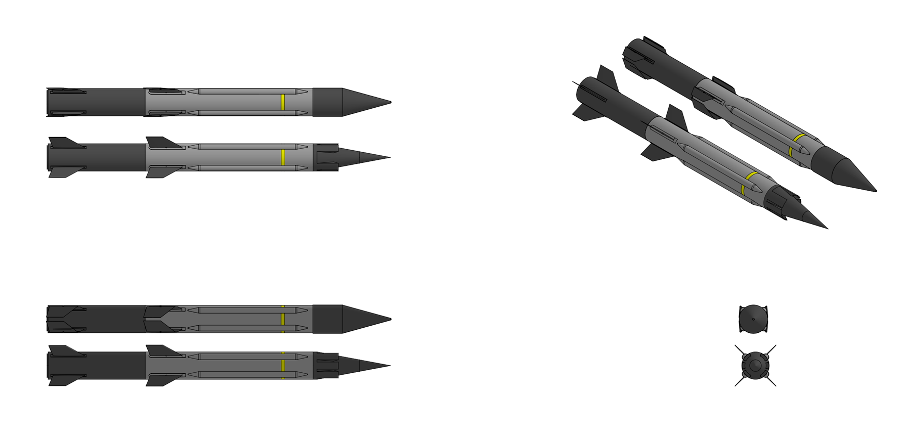
Last edited by The Technocratic Syndicalists on Sun May 03, 2026 8:08 pm, edited 58 times in total.
SDI AG
Arcaenian Military Factbook
Task Force Atlas
International Freedom Coalition


OOC: Call me Techno for Short
IC: The Kingdom of Arcaenia

User avatar
The Technocratic Syndicalists
Minister
 
Posts: 2350
Founded: May 27, 2015
Inoffensive Centrist Democracy

Postby The Technocratic Syndicalists » Sun Jun 18, 2017 11:51 pm

Image


RBS 91 Copperhead


General Characteristics:
Type:
Fiber-optic guided missile

Launch platform:
Ground vehicle, ship, helicopter

Guidance:
imaging infrared (IIR), INS/GPS, fiber-optic datalink

Physical Characteristics:
Weight:
50 kg

Length:
1.9 m

Diameter:
0.18 m

Warhead:
9 kg multi-purpose shaped charge

Performance Characteristics:
Propulsion:
Turbojet, solid rocket booster

Speed:
200 m/s

Range:
0.5 - 40 km


Overview:
The RBS 91 Copperhead is a surface and air launched long range fiber-optic guided missile designed to attack and destroy armored and unarmored vehicles, bunkers, helicopters, landing craft, fast attack craft, and other battlefield targets. The missile features an imaging infrared (IIR) seeker for day and night target acquisition which is coupled with a fiber-optic guidance wire which unrolls behind the missile in flight and allows the gunner to manually fly and target the missile from a control station inside a vehicle or ship.


Airframe & Propulsion:
  • Name: SDI RM70
  • Type: Turbojet
  • Length: 330 mm
  • Diameter: 170 mm
  • Dry Weight: 3.5 kg
  • Compressor: 1 stage centrifugal
  • Combustor: annular combustor
  • Turbine: Single stage
  • Maximum Thrust: 470 N
  • Overall pressure ratio: 3.4:1
  • Specific fuel consumption: 45 g/Kn-s
  • Thrust-to-Weight Ratio: 5.1:1
The Copperhead missile features a cylindrical S2 glass/epoxy filament-wound composite fuselage which is divided into four sections; the seeker section which contains the imaging infrared (IIR) seeker, cryogenic seeker coolant bottle, and precursor warhead, the warhead section which contains the main charge and electro-mechanical safe & arm device (ESAD), the integrated propulsion module (IPM) section which contains the missile's RM70 turbojet engine, inlet and exhaust ducts, fuel pump, fuel tank, and igniter cartridge, the booster section which contains the missile's integral solid rocket booster, the guidance section which contains a 6-axis inertial measurement unit (IMU), radar altimeter, and GPS receiver, the control section which contains the missile's four tail control fins and associated electro-mechanical control actuation system, and the fiberoptic datalink section with contains the reel-out fiber optic guidance wire. Lift is provided by four flip-out wings with a span of 1.4 meters while control is provided by four electro-mechanically actuated tail control fins which fold for storage inside a launch canister. The missile is launched using an integral solid rocket motor which accelerates the missile to an initial cruising velocity of 150 m/s where the missile's midbody wings and tail control fins are deployed and the the turbojet motor is ignited and used to propel the missile toward the target.


Guidance:
The Copperhead uses a 640 x 480 pixel platinum silicide (PtSi) focal plane array seeker mounted to a dual axis gyro-stabilized gimbal which is designed to provide all-weather day-and-night detection and identification of battlefield targets. The seeker operates in the MWIR band (3 to 5 μm) and is cooled to 80K using a nitrogen bottle contained inside the seeker section. The seeker has two selectable fields' of view including a 5.0° x 3.75°NFOV and a 10° x 7.5° WFOV and is mounted to a servomotor driven two-axis gimbal which allows the seeker to be steered +/- 30°in both azimuth and elevation. Midcourse guidance is provided by a 6-axis SDI TNS 450 tactical-grade timing and inertial measurement Unit (TIMU) which combines three milli-Hemispherical Resonator Gyroscope (mHRG) and three quartz resonating beam accelerometers (RBA) in a low SWaP package (500 cc volume, <1.0 kg mass, <5 watts max power consumption) package combined with a 24-channel SAASM (Selective Availability Anti-spoofing Module) based GPS receiver, digital autopilot computer, and a radar altimeter. The rear of the missile contains a fiber-optic bobbin which 240μm diameter fiber-optic cable which spools out behind the missile and links it with the control station on the firing platform. The fiber-optic cable has a maximum data transfer rate of 200 MB/s and serves to transmit the infrared video feed of the seeker to the control station and transmit control signals from the control station to the missile and unlike radio based datalink system provides the missile with immunity to active jamming and other forms of electromagnetic interference.

The guidance system of the Copperhead allows for both automatic or man-in-the-loop guidance modes. After launch the Copperhead is programmed to pitch over at an altitude of 200 meters where it then follows a constant-altitude cruise with a nominal cruise speed of 150 m/s towards the target area. In automatic mode the missile can be programmed to follow up to several hundred GPS waypoints along a pre-programmed route while the missile's seeker scans back and forth across the missile's ground track with a stepped-stair search to detect potential targets. During flight missile can be switched to manual operation mode where the gunner steers the missile with a joystick and can use the video feed from the infrared seeker to search for and acquire targets. When flying the missile manually the wide field-of-view (WFOV) mode is used to search for and acquire targets after which the gunner uses the narrow field-of-view (NFOV) mode for target identification and to lock the missile onto the target which is done by centering the crosshairs on the gunner's display with the desired target.


Warhead:
The Copperhead missile is equipped with an 8 kilogram multi-mode tandem shaped-charge (HEAT) warhead combing blast-fragmentation and shaped-charge effects which is effective against both armored and unarmored vehicles and structure targets. The main warhead consists of a 170mm diameter HF-1 high-fragmenting steel case containing 5.7 kilograms of polymer-bonded explosive (92% HNIW, 4.8% BDNPA/F, 3.2% CAB), copper shaped charge liner, syntactic foam wave-shaper, central and peripheral detonators, and aluminum electro-mechanical safe & arm device (ESAD) housing. An 83mm diameter precursor warhead employing a two-layered molybdenum shaped charge liner containing 1.0 kilograms of HNIW based polymer-bonded explosive, is located ahead of the main warhead in the seeker section of the missile and serves to defeat any explosive reactive armor (ERA) tiles on the target before the main warhead detonates. When used against armored vehicles the impact fuze is used and the warhead is detonated using the peripheral detonators which creates a high speed, small diameter penetrating jet capable of penetrating in excess of 1,500 mm RHA after ERA. For attacking soft targets a set of twin proximity fuzes in the nose of the missile can be used which allows the warhead to air-burst, the main warhead being initiated with the central and peripheral detonators which cause the warhead's copper shaped charge liner and high-fragmentation steel case to break up and release over 9,000 high-velocity steel and molybdenum fragments, creating a lethal-zone to exposed personnel over 40 meters in diameter
Last edited by The Technocratic Syndicalists on Thu Sep 05, 2024 8:20 pm, edited 28 times in total.
SDI AG
Arcaenian Military Factbook
Task Force Atlas
International Freedom Coalition


OOC: Call me Techno for Short
IC: The Kingdom of Arcaenia

User avatar
The Technocratic Syndicalists
Minister
 
Posts: 2350
Founded: May 27, 2015
Inoffensive Centrist Democracy

Postby The Technocratic Syndicalists » Sat Jul 29, 2017 4:16 pm

Image


GR 30 Viper


General Characteristics:
Type:
Air-to-ground guided rocket

Launch platform:
Helicopter, aircraft

Guidance:
Semi-active laser homing (SALH)

Physical Characteristics:
Weight:
18.0 kg

Length:
1,900 mm

Diameter:
81 mm

Warhead:
7.0 kg Blast/fragmentation or HEAT

Performance Characteristics:
Propulsion:
Solid fuel rocket

Speed:
650 m/s

Operational Range:
1.5 to 12 km (ground or hovering helicopter launch)


Overview:
The SDI GR 30 Viper is an 81 mm diameter fin-stabilized guided rocket system designed by SDI Missile Systems. The system consists of an 81 mm BR 30 unguided rocket which is fitted with a dual imaging infrared (IIR) and semi-active laser (SAL) guidance kit to convert it into a precision-guided rocket which can engage both stationary and moving targets. The Viper can be launched from a variety of pods capable of being mounted to rotary and fixed wing aircraft housing either 4, 6, 12, or 18 rockets.


Airframe & Propulsion:
The Viper rocket consist of three sections, guidance section which contains the semi-active laser seeke, steering canards, IMU, thermal battery, and guidance electronics, warhead section with either blast fragmentation or shaped charge warhead, and rocket propulsion unit which contains the rocket motor and rear stabilization fins. The rocket motor section weighs 8.7 kilograms and consists of a transversely wound glass/epoxy motor case which contains a radial burning insensitive minimum-smoke PGA/TMETN/ BTTN/RDX based extruded cross-linked double-base (XLDB) solid fuel propellant grain with a boron potassium nitrate (BKNO3) pyrotechnic igniter along with nozzle section with three wrap-around fins. The rocket motor provides 9.0 kN of peak thrust and burns for 0.85 seconds, accelerating the rocket to a burnout velocity of 650 m/s. The rear fin section of the propulsion unit has four flip-our stabilization fins curved to match the outside diameter of the rocket fuselage which flip out sideways to open. The nozzle additionally contains a set of flutes which impart a spin to the rocket as it fires to provide additional stabilization during launch.


Guidance
The Viper guidance system consists of an inertial navigation system and dual mode electro-optical seeker combining a 640 x 480 pixel uncooled long-wave (LWIR) imaging infrared (IIR) seeker and a semi-active laser (SAL) in a single, common-aperture co-boresighted package which supports both LOBL (Launch Before On-Lock) and LOAL (Launch After On-Lock) targeting modes. The imaging infrared seeker employs a 640 x 480 pixel 10-µm pixel pitch uncooled Vanadium Oxide (VOx) focal plane array detector with a 13° horizontal x 10° vertical field of view that detects thermal radiation in the 8-14 µm range. The laser seeker is designed to detect 1064 nm laser designators and has a ±50°field of regard with a ±30° field of view with a laser spot acquisition range of 2,000 meters. The laser guidance system provides a <1 meter CEP and can engage both stationary and moving targets (max target speed 100 km/h). The missile can attack targets in either IR mode, SAL mode, or laser offset mode. In IR mode, which is primarily intended for attacking moving and stationary ground vehicles, the missile is launched towards the vicinity of the target location and the imaging infrared seeker uses its onboard AI-based automatic target recognition (ATR) algorithms to search for and identify the target and select an aimpoint before impact. In SAL mode, which is primary used for attacking structures, either the launch platform or a forward observer located on the ground or in the air designates a target with a laser designator where the missile is launched to the target area and then detects and follows the laser guidance spot until impact. Laser offset mode is similar to SAL mode but is intended to prevent triggering any laser-warning receivers; a laser designator is used to designate a spot near the target and the IR seeker is used for terminal guidance and aimpoint selection. The rocket has two trajectory options: a lofted ballistic trajectory or a flat direct-attack trajectory.


Warhead
The Viper rocket is available with two different warhead options: a 7.0 kilogram blast-fragmentation warhead or a 7.0 kilogram high-explosive dual-purpose (HEDP) warhead. The 7.0 kilogram blast-fragmentation warhead is effective against light armored vehicles, SAM systems, small surface craft, reinforced concrete bunkers and structures, and building and consists of an internally scored hardened steel case containing 3.0 kilograms of insensitive polymer bonded aluminized enhanced blast-explosive (65% HMX, 30% aluminum, 5% Hytemp and DOA binder). The scored steel fragmentation sleeve is diagonally scored and breaks up into several thousand steel fragments which are lethal to exposed personnel within 15 meters. The warhead is detonated by a base mounted Electronic Safe and Arming Fuze (ESAF) which supports both point detonation and delayed fuzing modes. When used with delayed fuzing the warhead is capable of penetrating a 20 cm thick double reinforced concrete wall before detonating on the other side. The 7.0 kilogram high-explosive dual-purpose (HEDP) warhead is a multipurpose warhead which combines a shaped-charge for armor penetration for armored vehicles with a fragmentation sleeve to neutralize soft-target personnel and equipment. The HEDP warhead consists of a penetrating nose cap, an anti-armor hollow charge, and a pre-scored fragmenting casing, and a base mounted Electronic Safe and Arming Fuze (ESAF).
Last edited by The Technocratic Syndicalists on Fri Apr 24, 2026 8:31 pm, edited 16 times in total.
SDI AG
Arcaenian Military Factbook
Task Force Atlas
International Freedom Coalition


OOC: Call me Techno for Short
IC: The Kingdom of Arcaenia

User avatar
The Technocratic Syndicalists
Minister
 
Posts: 2350
Founded: May 27, 2015
Inoffensive Centrist Democracy

Postby The Technocratic Syndicalists » Sat Jul 29, 2017 7:17 pm

Image


RBS 98 Kestrel


General Characteristics:
Type:
Anti-Tank Guided Missile Launcher

Guidance:
Laser Beam Riding

Physical Characteristics:
Weight:
9.8 kg launch tube, 6.0 kg CLU

Length:
870 mm

Rocket Diameter:
140 mm

Warhead:
2.3 kg top attack EFP

Performance Characteristics:
Propulsion:
Two-stage solid fuel rocket

Speed:
300 m/s

Operational Range:
40 - 2,500 m


Overview:
The RBS 98 is a man portable top-attack anti-tank guided missile system designed to engage and destroy main battle tanks and and other armored fighting vehicles at combat ranges up to 2.5 kilometers. The weapon is small and light enough to be carried by a single soldier and gives individual soldiers the ability to engage and destroy heavily armored vehicles at typical combat ranges. The complete FGM-198 system consist of reusable command launch unit (CLU) and expendable launch tube assembly (LTA) containing the missile.


Command Launch Unit:
The command launch unit or CLU is the reusable targeting component of the system which is attached to the launch tube assembly before firing. The CLU weighs 6.0 kilograms and contains a second generation mercury cadmium telluride (HgCdTe) long-wave thermal (8 – 14 µm) imager with staring focal-plane array (FPA), a daylight CCD camera, eye-safe 2.1 μm holmium laser rangefinder, and 10.6 μm CO2 laser designator. The long-wave infrared imager features a 4X magnification wide field-of-view (WFOV) mode and 12X magnification narrow field-of-view (NFOV) mode while the daylight CCD camera features a fixed 4x magnification. Both thermal imager and CCD camera feature electronic auto-focus, 2-D image stabilization, and automatic target tracking (ATT) capability to allow for more effective target acquisition and engagement. A linear drive cryocooler contained in the CLU is used to keep the temperate of the focal plane array (FPA) of the infrared imager at around 70-100 degrees K. The CO2 laser designator is part of the laser beam-riding guidance system and produces an overlapping group of conical laser beams which are detected by a laser receiver on the tail of the missile which then steers the missile towards the operator's aimpoint where the laser designator beams intersect. The CO2 laser illuminator includes a variable focal length lens which decreases the diameter of the laser beam as the missile approaches the target to minimize the probable miss distance at the target. The CLU is powered by a rechargeable lithium-ion battery which give the CLU a battery life of around 16 hours before it needs recharging.


Missile:
The RB 98 missile is 140 mm in diameter, 850 mm long, and weighs 6.4 kg at launch (9.8 kg with its launch tube). The missile has a cylindrical body with four rear mounted flip-out fins for steering and stabilization which spring out as the missile is launched from the tube. The front of the missile features a blunted dome-like nose which contains a combined laser/magnetic target detection device (TDD) which is used to detect the target vehicle and trigger detonation of the top attack EFP warhead. The tail of the missile contains a laser receiver which is designed to measure the missile's deviation from the laser beam emitted by the CLU's CO2 guidance laser and sends steering commands to the missile's inertial autopilot based on the deviation from the guidance beam. The missile's inertial autopilot system contains a 3-axis fiber-optic gyroscope (FOG) and 3-axis accelerometer which stabilizes the missile in fight. The control logic of the laser beam-riding guidance system is designed to cause the missile to overfly the target vehicle by a height of approximately 0.75 meters at which point a combined laser and magnetic fuze triggers the missile's downward firing warhead. The EFP warhead weighs 2.3 kg and employs a dual tantalum liner and contains 1.05 kg of polymer bonded HMX explosive and can penetrate in excess of 130 mm of RHA, sufficient to penetrate the thinner top armor of most targets.

The rear part of the missile contains the propulsion section with two-stage soft launch system. The missile employs two motors in tandem separated by a burst disk with a common nozzle; a low-thrust launch motor which ejects the missile from the launch tube at a velocity of 25 m/s and a higher thrust flight motor which activates approximately 5 meters after the missile has cleared the launch tube and accelerates the missile to a maximum velocity of 300 m/s. The launch motor allows the missile to be launched from buildings or other enclosures without the risk of back-blast injury to the user. Both motors employ minimum smoke cross-linked doublebase (XLDB) propellant to minimize the launch signature of the missile. Stabilization is provided by four spring loaded fins located at the rear of the missile around the rocket motor case which spring out after the missile has cleared the launch tube to stabilize the missile in flight.


Launch Tube Assembly (LTA):
The missile launch tube assembly (LTA) consists of a straight cylindrical tube constructed from transversely wound fiberglass/epoxy with large foam rubber shock absorbers mounted at each end of the fiberglass launch tube and an L shaped foam rubber shoulder pad located on the underside in the middle of the launch tube. A locking hinge mounted to the launch tube is used to attach and detach the CLU.
Last edited by The Technocratic Syndicalists on Fri Aug 06, 2021 5:26 pm, edited 16 times in total.
SDI AG
Arcaenian Military Factbook
Task Force Atlas
International Freedom Coalition


OOC: Call me Techno for Short
IC: The Kingdom of Arcaenia

User avatar
The Technocratic Syndicalists
Minister
 
Posts: 2350
Founded: May 27, 2015
Inoffensive Centrist Democracy

Postby The Technocratic Syndicalists » Wed Aug 02, 2017 10:02 pm

Image


RBS 93 Onyx


General Characteristics:
Type:
Air-to-surface guided missile

Launch platform:
Rotary wing and fixed wing aircraft

Guidance:
Tri mode millimeter wave (MMW), imaging infrared (IIR), and semi-active laser (SAL) seeker

Physical Characteristics:
Weight:
54 kg

Length:
1.8 m

Diameter:
0.18 m

Warhead:
9 kg multi-function tandem shaped charge

Performance Characteristics:
Propulsion:
Solid fuel rocket

Speed:
550 m/s

Range:
16 km (rotary wing), 30 km (fixed wing)

Enviornmental Characteristics:
Operating Temperature:
46°C to +71°C

Shelf Life:
20 years


Overview:
The RBS 93 Onyx is an air-to-surface, fire-and-forget, anti-armor missile which can be launched from both rotary wing and fixed wing aircraft. The missile features a unique tri-mode seeker combining a millimeter wave (MMW) active radar, passive imaging infrared (IIR) detector, and semi-active laser (SAL) sensor into a common aperture effective at detecting and tracking moving and stationary targets in all weather conditions and a multi-purpose tandem shaped charge warhead effective against armored vehicles, buildings and bunkers, and small warships.


Airframe & Propulsion:
The RBS93 missile features a cylindrical fuselage divided into five sections; seeker section containing the missile's tri-mode seeker, counter-active protection system jammer, warhead precursor charge, and inertial measurement unit, warhead section with tandem shaped-charge warhead and electro-mechanical safe & arm device (ESAD), guidance electronics section which contains the missile's guidance computer and thermal battery, and propulsion & control section which contains the missile's solid fuel rocket motor and tail control fins and pneumatic control-actuation system. The missile also features a set of mid-body mounted fiberglass strakes to provide additional lift during flight. The missile's rocket motor is constructed from strip laminated maraging steel and contains a case bonded minimum smoke RDX based elastomeric modified cast double base propellant (12% NC, 37.5% NG, 40% RDX) which is ignited at launch using a 974 nm near-infrared diode laser and propels the missile off its launch rails to a burnout velocity of around 550 m/s. Maximum missile range is 16 km when fired from a hovering helicopter at low altitude or 30 km when fired from a fixed wing aircraft.


Guidance:
The RBS 93 missile features a tri-mode seeker combining a millimeter wave (MMW) active radar, passive imaging infrared (IIR) detector, and semi-active laser (SAL) sensor into a common aperture. The millimeter wave radar seeker is a W band (94 GHz) frequency-modulated continuous-wave (FMCW) seeker which is effective against land and sea targets in all weather conditions and in the presence of battlefield obscurants. The radar seeker employs a combination of high-resolution range profile (HRRP) and doppler beam sharpening (DBS) enhanced high-resolution burst-SAR mode to image both moving and stationary targets detected by the seeker for autonomous target recognition purposes. The radar seeker's ATR engine operates on a dedicated neural processing unit (NPU) within the seeker electronics module which ingests HRR target profiles and micro-Doppler signatures to classify targets into a library of several hundred threat vehicle types. The classifier employs a deep convolutional neural network trained on synthetic aperture radar imagery and real-world field collections. The ATR supports priority-based autonomous target selection during salvo engagements, enabling discrimination between high-value targets (MBTs, air defense systems) and lower-priority vehicles. The imaging infrared (IIR) seeker consists of a 640 x 512 pixel InGaAs (indium gallium arsenide) nBn type high-operating-temperature (HOT) staring focal plane array (FPA) detector array which operates in the MWIR (3-5 µm) band and provides passive day and night detection, identification, and aimpoint selection against moving and stationary vehicle targets. A micro-Integrated dewar cooler assembly with miniature stirling cooler contained inside the seeker assembly is used to keep the high-operating-temperature (HOT) detector at a temperature of 120K, higher than the 77K required of traditional cooled IR detectors and reducing the sight, weight, and power consumption of the cooling unit. The seeker has a a narrow field of view (NFOV) of approximately 2.5°×2.0° for tracking and a selectable wide field of view (WFOV) of 6.0°×4.8° for search and acquisition. The infrared ATR engine processes thermal imagery through a multi-stage pipeline including background segmentation, candidate detection, feature extraction, and deep-learning classification. The system uses a convolutional neural network (CNN) optimized for real-time inference on the onboard NPU, capable of classifying targets at a rate exceeding 30 frames per second. The ATR provides shape-based classification that is complementary to the radar’s signature-based approach, achieving a fused classification accuracy greater than 95% when both modalities are combined. The ATR system includes an aimpoint refinement algorithm that selects the optimal impact point on classified targets for maximum lethality, for example targeting the turret top or engine deck of an MBT rather than the most heavily armored frontal arc. The semi-active laser (SAL) detector consists of a four-quadrant indium gallium arsenide (InGaAs) photodiode array positioned behind the main IIR optics, using a dichroic beamsplitter to separate the 1.064 μm laser energy from the mid-wave infrared band. SAL mode enables engagement of targets designated by ground forward observers, other aircraft, or unmanned systems. SAL mode can also be used cooperatively with the autonomous modes, the SAL can provide initial cueing to a general target area, with the radar and IIR performing final acquisition and aimpoint selection autonomously. The SAL receiver has a coded pulse rejection capability to discriminate the intended designator in multi-laser environments.

The seeker mission computer implements a real-time multi-modal track fusion algorithm based on an extended Kalman filter architecture. Sensor measurements from all three channels are fused at the track level, producing a unified target state estimate (position, velocity, classification, aimpoint) that drives the guidance law. The mode manager autonomously selects the optimal sensor weighting based on environmental conditions, target characteristics, and engagement geometry. In clear conditions against moving armor, the system typically weights the IIR channel highest for aimpoint precision, with the radar providing range and velocity data. In degraded visual conditions (smoke, dust, fog, rain), the radar channel is weighted preferentially. The SAL channel, when active, provides a high-confidence position reference that anchors the autonomous tracker. This graceful degradation architecture ensures that the loss of any single sensor mode does not result in loss of the engagement. Midcourse guidance is provided by a 6-axis SDI TNS 500 tactical-grade timing and inertial measurement Unit (TIMU) which combines three MEMS (micro-electromechanical systems) quad mass gyroscopes (QMG) and three MEMS accelerometers in a low SWaP package (100 cc volume, 0.15kg mass, <2.5 watts max power consumption) package. The missile's onboard mission computer is built around multi-core system-on-chip (SoC) integrating a dual-core real-time processor for guidance and control functions, a dedicated neural processing unit (NPU) providing approximately 10 TOPS (tera-operations per second) for AI-ATR inference, and a programmable FPGA for radar signal processing and waveform generation.

The autonomous target detection and recognition capability tri-mode seeker enables the missile to be used in either direct attack modes including lock-on-before-launch (LOBL) and lock-on-after-launch (LOAL) modes along with various indirect attack modes including point, column, and area attack. The SAL seeker can also be used either alone or in combination with the MMW and IIR seekers to provide a man-in-the-loop targeting capability. In lock-on-before-launch (LOBL) mode the missile attacks targets which are first detected and tracked by targeting sensors on the launch platform. Targeting information from the launch platform including the target range, bearing, elevation, and type are handed off to the missile which then locks on to the target with its MMW seeker and/or IIR seeker while still on the launch rail. When the missile seeker has locked onto the target the infrared seeker image along with the MMW/IIR autonomous target recognition determination cam be displayed to the pilot or Copilot/gunner, allowing them to confirm that the missile has locked onto the desired target before the missile is launched directly at the target on either a lofted or direct attack trajectory. The high off-boresight (HOBS) capability of the seeker allows targets ±35° off the aircraft's flight path axis to be locked onto and attacked in direct-fire mode. In lock-on-after-launch (LOAL) mode the target coordinates, elevation, and type are handed off to the missile which is then fired towards the target grid coordinates while guided using it's IMU. At a distance of 2 to 3 kilometers from the target the missile then turns on its MMW seeker and scans a rectangular box around the target's grid coordinates. Detected targets are then classified using sensor fusion between the MMW and IIR seekers, with the missile prioritizing a target based on its determined type relative to the intended target and its position relative to the initial target grid coordinate. When a target has been selected the The IIR seeker is used for terminal tracking and aimpoint selection with MMW used as a backup should the target become obscured, with warhead mode selected by the missile's guidance system based on the type of target.

In indirect modes the missile is launched at targets not directly visible to the launch platform where the missile is launched towards a target are and programmed to search for targets and attack targets autonomously with its seeker. Before launch each missile is programmed with the intended target search area including start search and stop search distances, a self destruct point, and the desired attack mode (either point, column, or area). Following launch missile first guides itself to the predicted target location using it's IMU where upon reaching the target area the MMW seeker is activated first and performs a push-broom scan of the target area to detect potential targets, initially prioritizing them based on their location and velocity within the programmed search zone. The IIR seeker will be then be activated and both MMW and IIR seekers will perform automatic target recognition (ATR) in tandem to determine which targets in the target area should be attacked. Three indirect fire modes are supported by the weapon; point attack, column attack, and area attack. In point attack mode a single missile is programmed to search a given target area defined by the launch aircraft for a specific target. After launch the missile performs a flyout to the designed target area where the missile then climbs or descends to a programmed search altitude and activates its seeker which sweeps back and forth across the ground track corresponding to the ground search area defined before launch. When the desired target is acquired the missile is programmed to perform a terminal dive down onto the target, striking its more vulnerable top armor. If the seeker does not detect the target in the defined search area the missile is programmed to fly to a designated self destruct point outside of the target search area before self destructing. In column attack 4 to 16 missiles are fired at a column of tanks or other vehicles with each missile fired attacking the nth target in the column. The mode is similar to point attack mode is except the missile search area for each missile fired is programmed to correspond to the approximate length and width of the target vehicle column. The first missile which enters the search area is programmed to attack either the first or last vehicle it detects, the second missile then attacking the second or second-to-last target, etc, until all vehicles in the column have been attacked and destroyed. The automatic-target-resolution capability of the seeker allows for wheeled or soft-skinned vehicles in a column of tanks or other tracked vehicles to be ignored, if so desired. In area attack mode 4 to 16 missiles are fired to search and attack a programmed target area containing multiple target vehicles. This mode is also similar to point attack mode but involves a much larger search area corresponding to a dispersed battlefield target such as a tank company or surface-to-air missile site. In area attack mode each missile will be programmed to fan out and search an area within the larger target area determined by the target position, weapon number and release order, attacking any targets it detects.

In addition to the MMW/IIR modes the missile also supports two semi-active laser modes: laser designate and laser anoint. Laser designate mode uses the missile's SAL seeker exclusively and homes in on targets designated by either the launch platform (LOBL) or a third party (LOAL) with a 1.06 µm laser designator. This mode is useful for attacking targets in cluttered environments or targets the MMW and IIR seekers are not suited to detect such as bunkers or earthworks or heavily camouflaged targets. In laser designate mode the user selects the desired trajectory (either lofted or direct attack) and selects the desired warhead mode before firing the missile. In laser anoint mode the missile used all three seekers at once, homing in on a laser spot from either the launch platform or a third party while using its MMW and IIR seekers to lock on to the designated target or whichever detected target is detected closed to the laser spot. In this mode the launch platform or offboard designator can que the missile to attack a specific target, with the ability to lase next to the intended target rather than directly as to avoid triggering laser warning receivers on the target. Like with laser designate mode in laser anoint mode the user selects the desired trajectory (either lofted or direct attack) with warhead mode and aimpoint selection being handled automatically by the seeker.

For defeating targets equipped with active protection systems the seeker section of the missile also contains a counter-active protection system jammer designed to disable the APS fire control radar so that the targeted vehicle remains vulnerable to the missile. The Counter-Active Protection System is housed in a compact annular module located around the forward radome section of the missile, occupying the volume between the inner seeker assembly and the outer airframe skin, The primary CAPS effector is a miniaturized solid-state electronic jammer operating in the frequency bands used by known threat APS engagement radars (primarily Ku-band and Ka-band, 12–40 GHz). The jammer employs a wideband digital RF memory (DRFM) architecture that intercepts the APS radar’s interrogation pulses, generates coherent false target returns, and retransmits them with calibrated time delays and Doppler shifts. This technique creates a dense cluster of phantom targets around the real missile return, confusing the APS fire control computer’s tracking and intercept solution. The jammer uses a compact conformal antenna array integrated into the radome surface, generating a jamming waveform which is emitted in a +/- 10° cone in the direction of target.. A threat warning receiver continually monitors for APS radar emissions during the terminal phase (final 2–3 seconds of flight) and autonomously activates the jammer upon detection. The jammer can produce over 50 simultaneous false targets within the APS radar’s resolution cells, reducing the probability of successful APS intercept by a factor of 10 or more. In addition to active jamming, the missile employs a terminal maneuver capability to further complicate the APS engagement timeline. The guidance computer commands a pseudorandom lateral jink maneuver during the final seconds of flight, varying the missile’s line of approach by up to ±2° from the predicted trajectory. While this deviation is small enough that warhead effectiveness is not significantly degraded, it introduces sufficient tracking uncertainty to cause APS interceptors to fire at a predicted intercept point that the missile no longer occupies. The combination of active jamming and evasive maneuver is estimated to reduce hard-kill APS effectiveness by 80–90%


Warhead & Fuzing:
The RBS 93 missile is equipped with a 9.0 kilogram multi-mode tandem shaped-charge (HEAT) warhead which can be triggered in either shaped-charge or blast-fragmentation modes for use against both armored and unarmored targets. The main warhead consists of an hardened steel case containing 5.7 kilograms of polymer-bonded explosive (92% HNIW, 4.8% BDNPA/F, 3.2% CAB), a 143mm diameter variable thickness molybdenum elliptical shaped charge liner, a PEGAB (PolyEster with GlAssBubbles) wave-shaper, central and peripheral detonators, and an aluminum electro-mechanical safe & arm device (ESAD) housing. A precursor warhead employing an 83mm diameter two-layered molybdenum shaped charge liner and containing 1.0 kilograms of additional HNIW based polymer-bonded explosive, is located ahead of the main warhead in the seeker section of the missile and serves to defeat any explosive reactive armor (ERA) tiles on the target before the main warhead detonates. When used in shaped charge mode a crush switch in the seeker section sends a firing signal to the ESAD which then triggers the warhead's precursor charge. After a short delay, sufficient to allow the precursor charge to clear any explosive reactive armor on the target, the main charge is then detonated using the peripheral detonators which creates a high speed, small diameter penetrating jet capable of penetrating more than 1,700 mm RHA after ERA. In blast-fragmentation mode the precursor warhead is detonated on impact using the crush switch, the main warhead then detonated either immediately or after a time delay, the main warhead being initiated with both the central and peripheral detonators which causes the main warhead's molybdenum shaped charge liner and hardened steel case to break up and release over 9,000 high-velocity fragments, creating a lethal-zone to exposed personnel over 40 meters in diameter. The main warhead can also optionally be initiated using a forward looking radar proximity fuze in the seeker section of the missile with a set 3 meter (+/- 1 meter) burst height. Depending on the target the warhead can be set to function in four modes; shaped charge mode with impact fuzing for armored vehicle targets, blast-fragmentation mode with delay fuzing for use against light vehicles or structures, and blast-fragmentation mode with either impact or combined impact and proximity fuzing for use against personnel and light material targets. When used in semi-active laser designate mode the warhead mode is selected manually while in all other modes warhead mode is set automatically based on the type of detected target.
Last edited by The Technocratic Syndicalists on Tue Apr 28, 2026 12:38 pm, edited 24 times in total.
SDI AG
Arcaenian Military Factbook
Task Force Atlas
International Freedom Coalition


OOC: Call me Techno for Short
IC: The Kingdom of Arcaenia

User avatar
The Technocratic Syndicalists
Minister
 
Posts: 2350
Founded: May 27, 2015
Inoffensive Centrist Democracy

Postby The Technocratic Syndicalists » Sat Aug 05, 2017 12:11 am

Image


Rb 85


General Characteristics:
Type:
Short range surface-to-air missile

Launch platform:
Vehicle

Guidance:
laser beam-riding

Physical Characteristics:
Weight:
85 kg

Length:
2.4 m

Diameter:
0.165 m

Warhead:
12.5 kg dual mode self forging fragment

Performance Characteristics:
Propulsion:
Solid-fuel rocket

Speed:
Mach 5 (1.6 km/s) burnout

Maneuverability:
70 G

Operational range:
1-16 km

Flight altitude:
0-8 km


Overview:
The Rb 85 is a short range hypervelocity surface-to-air missile used by SDI's RBS 85 Manticore short range air defense system.


Airframe & Propulsion:
The Rb 85 missile consists of four sections: the missile's nosecone containing a contact fuze for the warhead along with the missile's guidance electronics including fiber-optic inertial measurement unit, thermal battery, and guidance computer, the warhead section which contains the missile's 12.5 kg focused fragment warhead and laser proximity fuze, the rocket motor section which contains the missile's solid fuel rocket motor, and the control section which contains the missile's four flip-out tail control fins and control actuation system. The missile is powered by a 1.5 meters long, 40 kilogram solid-fuel rocket motor consisting of a filament-wound carbon-fiber-reinforced polyetheretherketone (CFR-PEEK) case with an internal aramid-filled ethylene propylene diene monomer (EPDM) insulation and and an external sacrificial kevlar fiber/phenolic composite overwrap with CFR-PEEK forward and aft skirts and aluminum forward attachment and aft skirt rings, an aluminum blast tube and nozzle exit cone with silica phenolic reinforced resin external insulation and erosion resistant carbon/carbon phenolic internal liner, a case bonded GAP/HMX/ADN (25.5% GAP, 4.5% Plasticizer, 58.5% ADN, and 11.5% HMX) insensitive high-performance smokeless propellant grain, and a forward mounted laser igniter/safe/arm assembly which seals the forward end of the motor. The motor's GAP/HMX/ADN propellant has a higher burning rate and specific impulse than traditional Al/AP/HTPB composite or double base propellant and is completely smokeless, enabling easier tracking of the missile by the launch vehicle's targeting sensors and proving less visual approach warning to the target. The motor employs a boost-sustain propellant grain with a 7:1 thrust ratio which provides a peak thrust of 170 kN and accelerates the missile at over 450 g to a velocity of mach 5.0 in just under 1.5 seconds. The missile steers using an integrated aerofin thrust vector control (IATVC) system with four hydraulically actuated tail fins and a jet-vane thrust-vector control (TVC) system employing four C/Sic ceramic matrix composite jet vanes actuated using the same hydraulic actuators as the missile's control fins which gives the missile up to 70 g maneuver capability at ranges up to 8 kilometers.


Guidance:
After launch the missile and target are tracked by the vehicle's infra-red and electro-optical tracking sensors and steering instructions are sent to the missile using a 1.064 μm laser which transmits encoded pulses to a set of rear-facing laser detectors on the missile's fins. The guidance laser is part of the laser beam-riding guidance system and produces an overlapping group of conical laser beams which are detected by a group of four laser receivers on the tail fins of the missile which is then used by the missile's autopilot to steers the missile towards the aimpoint where the laser designator beams intersect. The laser illuminator includes a variable focal length lens which decreases the diameter of the laser beam as the missile approaches the target to minimize the probable miss distance at the target.


Warhead
The missile contains a 12.5 kilogram dual mode self-forging fragment (SFF) warhead which is able to produce either large, high velocity self-forging fragments for use against armored fixed and rotary wing targets or larger numbers of smaller fragments for use against unarmored or smaller targets. The warhead consists of an aluminum sleeve containing 96 tantalum-tungsten alloy (Ta-2.5%W) shallow dish liners in 12 rows of 8 liners each with 12 points of central and peripheral initiation along the warhead axis. The warhead contains a central core of 6.0 kilograms of polymer bonded HMX explosive (96% HMX, 4% DOA/Estane binder) which when detonated using the central detonators turns the shallow dish liners into explosively formed penetrators or a self-forging fragments which project radially around the axis of the warhead, each capable of penetrating over 25 mm of RHA at a distance of 8 meters from the warhead. When detonating using both the peripheral and central detonators the molybdenum shallow dish liners each break up into multiple smaller fragments, creating a high density cloud of tantalum fragments. The warhead is triggered using a laser proximity fuze which is activated by the missile's onboard firing circuit processor at a time between 0.2 and 0.5 seconds before the projected target interception point is reached. Lethal radius of the warhead is 8 meters in either mode,.
Last edited by The Technocratic Syndicalists on Mon May 11, 2026 8:59 am, edited 20 times in total.
SDI AG
Arcaenian Military Factbook
Task Force Atlas
International Freedom Coalition


OOC: Call me Techno for Short
IC: The Kingdom of Arcaenia

User avatar
The Technocratic Syndicalists
Minister
 
Posts: 2350
Founded: May 27, 2015
Inoffensive Centrist Democracy

Postby The Technocratic Syndicalists » Tue Aug 08, 2017 12:07 am

Image


Rb 79 Hydralisk


General Characteristics:
Type:
Exo-atmospheric anti-ballistic missile interceptor

Launch platform:
Ship VLS, TEL

Guidance:
IIR, INS/GPS, 2-way RF datalink

Physical Characteristics:
Weight:
10,400 kg

Length:
12.0 m

Diameter:
1.0 m

Warhead:
16x miniature kill-vehicles

Performance Characteristics:
Propulsion:
Three stage solid fuel rocket

Speed:
8.0 km/s burnout

Intercept range:
200 - 4,500 km

Intercept altitude:
100 - 2,000 km


Overview:
The Rb 79 Hydralisk is an advanced strategic exo-atmospheric midcourse interceptor designed by SDI Missile systems. The Rb 79 is designed to intercept MIRVed ballistic missile armed with multiple independently targeted reentry vehicles and protected by a cloud of countermeasures and carries a Multi-Object Kill Vehicle (MOKV) payload that deploys 16 miniature kill vehicles (MKVs) each capable of independently homing on and destroying a separate target.


Airframe & Propulsion:
The Rb 79 is a four stage missile and consists of a three stage solid booster stack which deploys a multi-object kill vehicle bus. The first stage motor is a 100 cm diameter, 6.2 meter length solid rocket motor. The case is filament-wound T1100G-class carbon fiber with co-cured integral insulation containing approximately 5,700 kilograms of high energy HNIW/GAP/Nano-Al propellant (60% HNIW, 25% GAP, 15% nano-AL). The motor grain is a 13-point star configuration delivering approximately 1,500 kN of peak thrust and 1,200 kN of average thrust over a 30 second burn. The nozzle is submerged-inlet with a 3D-woven carbon-carbon throat and 12:1 expansion ratio and provides a 275 second specific impulse at seal level. Thrust vector control is provided by a gimballed nozzle with ±4 °deflection. Stage separation uses a frangible joint fractured by linear detonating cord. The second stage is a 100 cm diameter, 2.5 meter long motor optimized for sustained thrust above 50 km altitude. The case is the same T1100G/cyanate-ester composite and contains 2,600 kilograms of the same HNIW/GAP/Nano-Al propellant blend with a cylindrical-perforation center-bore grain and delivers an average thrust of 600 kN over a burn of approximately 45 seconds. The nozzle has a 50:1 expansion ratio achieved through a deployable carbon-carbon exit-cone extension that unfolds after first stages separation a results in a second stage vaccum isp of 290 seconds. The third stage motor is 0.56 meters in diameter, 1.0 meters long, and contains 225 kilograms of HNIW/GAP/Nano-Al propellant. The third stage is a triple-pulse motor with three 10-second burns each with a peak thrust of 50 kN and a vaccum specific impulse of 290 s and provides additional acceleration and divert capability for the multi-object kill vehicle payload. The third stage carries the midcourse avionics package in a forward equipment bay including the ring-laser-gyro IMU, GPS receiver, X/S band datalink transceiver, flight computer, and thermal battery. A star tracker is integrated into the forward adapter for stellar-inertial updates during the exo-atmospheric coast phase.


Kill Vehicle:
The interceptor Multi-Object Kill Vehicle (MOKV) payload consists of a Carrier Vehicle (CV) bus and sixteen Miniature Kill Vehicles (MKVs). The CV and MKVs are integrated into a single payload module approximately nested inside the payload bay fairing during atmospheric flight. After second stage burnout and fairing jettison, the CV separates from the second stage on a spring-loaded ejection mechanism and begins its autonomous operations. The CV is a 20 cm diameter, 125 cm long cylindrical spacecraft which provides target observation, discrimination, and miniature kill vehicle (MKV) assignment and dispensing. The kill vehicle is nested within the interceptor's nosecone during boost and exposed at bus separation when the nose cone is jettisoned. The MOKV bus separates from the third stage after third stage burnout and fires a settling burn to orient its primary sensor toward the predicted threat-cluster bearing. The bus structure is a monocoque cylinder machined from aluminum-lithium alloy (Al-Li 2195). The forward end houses the dual-band IIR sensor behind a multi-spectral sapphire window. The mid houses the solid-propellant DACS gas generator, thruster ring, and the propellant charge. The aft section contains the avionics bay including discrimination processor, IMU, star tracker, datalink transceiver, AI mesh controller, power supply. The sixteen MKVs are arranged in two circumferential rows of eight around the CV’s outer surface, mounted on spring-loaded deployment rails. Each rail is oriented radially outward, so that when a deployment command is issued, the rail’s spring ejects the MKV perpendicular to the CV’s longitudinal axis at a separation velocity of approximately 2 to 5 m/s. The two rows are staggered longitudinally (fore and aft rows offset by 22.5 degrees in azimuth) to avoid mechanical interference during deployment. All sixteen MKVs can be deployed simultaneously for maximum dispersal speed or sequentially for controlled, targeted deployment over several seconds. The deployment sequence is commanded by the CV’s processor based on the target assignment algorithm.

The bus’s primary sensor is a wide-field-of-view cryogenic IIR telescope with a 1280 × 1024 pixel stacked dual-band focal-plane array detector in which two HgCdTe detector layers are grown epitaxially on a single substrate. The upper layer detects MWIR (3–5 µm) radiation, while the lower layer which receives photons that pass through the first layer, detects LWIR (8–12 µm). The combined array has 1280 × 1024 pixels per band, read out simultaneously through a single readout integrated circuit (ROIC), providing pixel-registered two color imagery of every object in the field of view. The cryocooler is a pulse-tube design achieving 60 K operating temperature within 3 seconds. The telescope aperture is approximately 20 cm, detecting thermal signatures of reentry vehicles and decoys at 200 to 500 km range against the cold space background. The 12° wide field of view encompasses an entire MIRV deployment cluster at typical engagement ranges with approximately 200 microradian pixel resolution. The 2° narrow field of view yields an angular resolution of approximately 35 microradians per pixel, sufficient to resolve the spatial extent of a 1-meter-diameter reentry vehicle at a range of 30 kilometers or to detect it as a point source at over 200 kilometers. The sensor observes the cluster continuously from bus separation until MKV dispensing (30 to 90 seconds), building a multi-frame dataset of each object’s thermal signature, rotational dynamics, and relative motion. By measuring each object’s thermal emission in two widely separated infrared bands simultaneously the discrimination processor can compute the object’s apparent color temperature and emissivity ratio. The two-color discrimination technique is far more robust than single-band intensity measurement alone and is extremely difficult for an adversary to defeat, as it would require matching both the absolute emission intensity and the spectral shape of the decoy to the RV across two bands simultaneously. The CV’s processor analyzes the LWIR/MWIR brightness ratio, temporal variability, spatial extent, and polarimetric properties of each object in the threat cloud to classify it as a warhead, lightweight decoy, heavy decoy, or debris. This onboard discrimination directly drives the MKV target-assignment algorithm, ensuring that MKVs are preferentially directed at objects classified as warheads. A secondary compact CMOS-based star tracker with a 10° FOV provides sub-arc-second absolute attitude fixes for sensor boresighting and MKV dispensing-angle computation. The CV discrimination processor a radiation-hardened multi-core SoC delivering approximately 30 TOPS performance, running deep-learning classification models trained on millions of simulated threat scenarios. The processing pipeline operates in three stages: a multi-hypothesis tracker that maintains separate tracks on every resolved object, a feature-extraction module computing thermal intensity, spectral shape, apparent size, spin/tumble rate, trajectory curvature, and cluster position for each tracked object, and a deep ensemble classifier (convolutional and recurrent neural networks) that maps feature vectors to RV/decoy/debris probability distributions. The classifier’s output drives the MKV assignment algorithm, which allocates MKVs based on a cost-benefit optimization accounting for inventory, consequence of missing a real RV, and cost of wasting an MKV on a decoy. The bus carries a dedicated AI mesh-network controller—a radiation-hardened neural-network accelerator integrated into the discrimination processor SoC that manages all three levels of the collaborative engagement architecture: MKV-to-MKV coordination within the deployed swarm, bus-to-MKV command and telemetry, and bus-to-bus collaboration when multiple interceptors are in flight. The controller runs a real-time multi-agent reinforcement-learning model that continuously optimizes the global target-assignment problem across all available MKVs and all observed threat objects, accounting for each MKV’s position, velocity, remaining delta-V, seeker track quality, and target classification confidence. When the ship launches two or more Rb 77E interceptors against the same threat cloud the buses establish a Ka-band directional data link and begin sharing discrimination data and target assignments. The AI coordinators on each bus negotiate a joint assignment plan that deconflicts their MKV deployments: Bus A’s swarm attacks objects 1 through 14, Bus B’s swarm attacks objects 15 through 28, with no duplication. If one bus’s swarm achieves early kills and has reserve MKVs, the coordinator can re-assign those MKVs to support the other bus’s remaining targets.

The bus DACS is a solid-propellant gas-generator system employing single solid-propellant charge of a cool-burning, low-smoke GAP/NEPE formulation optimized for sustained, controllable gas production at approximately 35 bar manifold pressure. The charge burns for at least 120 seconds, feeding a ring of 180 micro-nozzles arranged circumferentially around the bus for divert and 12 larger attitude-control jets for pitch, yaw, and roll. The divert thrusters produce a combined peak force of approximately 800 N, yielding approximately 5 g of acceleration at the CV’s loaded mass. Total divert delta-V is approximately 400 m/s, sufficient for the CV to traverse the extent of a typical threat cloud and to position itself at the optimal deployment point. The CV navigates using a stellar-inertial system comprising a ring-laser-gyro IMU and a wide-field star tracker. The star tracker provides absolute attitude fixes with sub-arcsecond accuracy by matching observed star patterns against an onboard catalog, bounding inertial drift to negligible levels over the 5–10-minute flight time from launch to MKV deployment. An embedded GPS receive provides backup position and velocity data when satellite visibility is available. An X-band two-way datalink connects the CV to the launching ship’s combat system, providing midcourse guidance updates, target cueing from shipboard and off-board sensors, and downlinking threat-cloud imagery and discrimination results. A Ku band mesh-network radio connects the CV to its sixteen deployed MKVs, transmitting target assignments, receiving MKV status reports, and relaying inter-MKV coordination messages. An optical crosslink (a modulated laser transceiver at 1.55 µm) enables CV-to-CV communication when multiple interceptors are launched at the same threat complex, supporting the multi-CV collaborative engagement algorithm.

The MKVs is a 2.0 kilogram, fully autonomous kinetic interceptor that independently acquires, tracks, discriminate, and impacts its assigned target. Each MKV consists of a seeker (approximately 300 g), solid DACS (approximately 900 g of which approximately 550 g is propellant), the avionics and processor (approximately 200 g), the power supply (approximately 150 g), the structure and thermal protection (approximately 300 g), and the communications module (approximately 50 g). The MKV optics are a miniaturized Cassegrain telescope with a germanium primary mirror and a zinc-selenide secondary, feeding a 640×480 pixel VOx microbolometer FPA operating in the LWIR (8–12 µm). The FPA has an NETD below 40 mK at f/1, detecting RV thermal signatures at 30 to 50 km range against the cold space background. The primary sensor of each MKV is a 640×480 pixel VOx microbolometer FPA operating in the LWIR (8–12 µm) band with a NETD below 40 mK at f/1, detecting RV thermal signatures at 30 to 50 km range against the cold space background. Uncooled operation eliminates the mass and power penalties of a cryocooler. The optic is an 8-centimeter (80 mm) diameter germanium/zinc-selenide doublet lens optimized for LWIR transmission. The optics have a dual field of view with an 8° acquisition FOV that ensures target capture at handoff from the bus, and a 1.8° narrow FOV used for terminal engagement. The sensor has no gimbal, the MKV steers its body to point the seeker using its DACS for attitude control. The seeker’s AI-based target classifier computes the LWIR brightness-temperature ratio for the target at each frame (50 Hz). The classifier is a lightweight convolutional neural network trained on millions of synthetic target scenes, running on the MKV’s 8-TOPS SoC. If the classifier determines with high confidence that the assigned target is not an RV, the MKV broadcasts this reclassification over the mesh network, and the swarm’s AI coordinator re-optimizes the global assignment, potentially directing this MKV or a nearby MKV to an unengaged RV-like object.

The MKV’s DACS is a miniaturized solid-propellant gas-generator system based on MEMS-fabricated valve technology. The gas generator is a single solid-propellant grain NEPE/GAP grain of approximately 550 grams that burns for 30 to 40 seconds, producing combustion gas at approximately 20 bar that is distributed through a miniaturized manifold to 32 micro-nozzles arranged in a circumferential ring around the MKV’s midsection (or lateral divert and 8 smaller attitude-control nozzles arranged in orthogonal pairs for pitch, yaw, and roll control. Each micro-nozzle is controlled by a silicon-based micro-valve with a throat diameter of approximately 0.5 millimeters, fabricated using deep-reactive-ion-etching (DRIE) processes. These valves achieve response times of approximately 1 millisecond at power consumption of less than 100 milliwatts each, enabling rapid pulse-modulated thrust control at the 200 Hz guidance loop rate. The entire 32-valve divert array and 8-valve ACS array are fabricated as a single MEMS wafer stack, bonded to the gas manifold, providing an integrated propulsion module that weighs less than 350 grams including all valves, nozzles, manifold, and housing. The divert thrusters produce a combined peak lateral force of approximately 30 N, yielding over 15 g of lateral acceleration at the MKV’s 2.0 kg initial mass. Total divert delta-V exceeds 500 m/s, sufficient for midcourse engagements where the MKV is deployed within a few kilometers of its target and closing velocities are 5 to 15 km/s. The 15 g acceleration enables the MKV to correct a 100 meter heading error in approximately 0.8 seconds at 15 g, which corresponds to a slant range of approximately 5 kilometers at a 10 km/s closing velocity, well within the seeker’s tracking capability.

The MKV’s processor is a custom RISC-V SoC fabricated on a 7 nm radiation-hardened process, delivering approximately 8 TOPS of inference throughput at approximately 2.5 watts. The SoC integrates the seeker signal processor, the target classifier (CNN), the proportional-navigation guidance law with AI-augmented acceleration estimation, the DACS control loop at 50 Hz, and the mesh-networking stack. The AI mesh transceiver operates on S-band with a 10 Hz broadcast rate, transmitting the MKV’s current target track, classification assessment, DACS state (remaining delta-V, propellant time), and intercept prediction. The mesh protocol is a gossip-based flooding algorithm that ensures every MKV in the swarm receives every other MKV’s state within two broadcast cycles (200 ms), enabling swarm-wide situational awareness with minimal latency. The MKVS IMU is a low SWaP-C (<10 cc, 25 g, <0.5W) micro-electro-mechanical system (MEMS) 9-axis based (3-axis gyroscope, 3-axis accelerometer, 3-axis magnetometer) inertial measurement unit (IMU) providing < 10° gyro bias stability and <0.5°√hr gyro angle walk performance. Power is provided by a lithium-thionyl-chloride primary battery delivering approximately 8 watts for 90 seconds, sufficient for the MKV’s full autonomous flight from dispensing to impact.


Guidance:
The interceptor engagement consists of boost and midcourse flight to the threat cloud, CV threat-cloud survey and discrimination, MKV target assignment and deployment, MKV autonomous terminal homing with mesh coordination, and impact and kill assessment. The Rb 79 first launches from the ship, boosts through both stages, and separates the MOKV payload above the atmosphere. The CV then orients itself and navigates using stellar-inertial guidance and receives midcourse updates over the X-band datalink from the ship. The fire-control system provides initial cueing of the threat cloud’s estimated position, velocity, and composition based on ship radar tracking, satellite infrared and radar tracking. As the CV approaches the threat cloud from 200+ km range its stacked dual-band telescope acquires the cloud and begins cataloging all objects. The AI discrimination algorithm classifies each object based on its LWIR/MWIR brightness ratio, temporal thermal variability (warheads have more stable temperatures than thin-walled decoys that heat and cool with solar angle changes), apparent angular extent (large balloons vs. compact RVs), tumble rate (stable warheads vs. tumbling debris), and spectral emissivity profile. The classifier produces a probability-of-warhead score for each object, ranked from highest to lowest. The CV’s processor runs the target-assignment algorithm, which maps the sixteen available MKVs to the sixteen highest-priority targets (those with the highest probability-of-warhead scores). Each MKV is assigned a specific target with an initial bearing and range estimate. The CV then maneuvers its DACS to position itself at the centroid of the target set (minimizing the average MKV flyout distance) and deploys the MKVs in a pre-computed sequence designed to distribute them evenly across the threat cloud. Deployment is typically completed within 5 to 10 seconds. After deployment, each MKV activates its seeker, acquires its assigned target, and begins autonomous proportional-navigation guidance. Simultaneously, the MKVs establish a Ku band mesh network among themselves and with the CV. Over this network, each MKV broadcasts its target’s updated position, its own state vector, and its target classification update as its seeker resolves more detail during closure. MKVs approaching the threat cluster from different angles observe each target at different aspect angles. By sharing their imagery via the mesh network, the swarm’s AI can perform multi-aspect thermal tomography, combining views from two or more MKVs to reconstruct the target’s three-dimensional thermal emission pattern. The distributed consensus algorithm prevents duplicate targeting: if two MKVs determine that they are homing on the same object, the algorithm reassigns one to the nearest unattended target. If an MKV determines that its target is a confirmed decoy, it autonomously re-targets and broadcasts this reclassification. The swarm AI on every MKV then re-evaluates the global assignment. Each MKV impacts its target at closing velocities of 5 to 15 km/s. The CV, which has maneuvered to a standoff observation position behind the MKV swarm, observes the impacts using its high-resolution telescope, detecting the optical flash and debris signature of each hit. When an MKV impacts its target, nearby MKVs also observe the impact flash and debris signature with their dual-band seekers. The swarm AI then compares the observed debris pattern to pre-trained models of successful versus unsuccessful kills. If the assessment indicates a miss or a survivable hit, the nearest MKV with remaining delta-V and an unassigned or low-priority target can be re-directed to re-engage the surviving object. Kill assessment data is downlinked to the ship via the X-band datalink, providing the fire-control system with a real-time accounting of how many objects were destroyed. If any warheads remain unengaged, a follow-on interceptor can then be launched.

When the threat cloud contains more objects than a single sixteen MKVs can cover the fire-control system launches two or more Rb 79 interceptors. As the CVs approach the threat cloud, they establish datalink crosslinks and exchange their respective threat-cloud catalogs, discrimination assessments, and MKV inventories. The multi-CV collaborative algorithm partitions the target set among the available CVs, assigning each CV a subset of the threat cloud that its MKVs will cover. As the two buses observe the threat cluster from different angles (as they will if launched at different times or on different trajectories), they share their dual-band imagery where the joint discrimination processor fuses both datasets to produce a higher-confidence classification of each object than either bus could achieve alone. Objects that are ambiguous from one viewing angle may be clearly identifiable from another. The AI coordinators then jointly solve the assignment problem across both swarms, ensuring no two MKVs from different buses are assigned to the same target. Bus A’s swarm covers one sector of the threat cluster; Bus B’s swarm covers another. If one sector has more RVs than the other, the AI shifts more MKV assignments to balance the load. The partitioning is optimized to minimize the total MKV flyout distance, reducing DACS propellant consumption, and to ensure that every warhead-probable object is assigned to at least one MKV. If the total MKV count (32 for two interceptors, 48 for three) exceeds the number of warhead-probable objects, the surplus MKVs are assigned to the next tier of ambiguous objects, then to heavy decoys, and finally held in reserve. After MKV deployment, the mesh network extends across both CV’s MKV swarms, creating a single cooperative engagement space in which all 32+ MKVs coordinate their targeting. A deployed MKV from CV-1 can communicate with and receive re-targeting commands from CV-2’s MKV swarm, ensuring that the global target set is covered without gaps or redundancies. This seamless multi-CV coordination is enabled by the AI-driven distributed consensus protocol, which operates without a central controller, if any CV or MKV is destroyed during the engagement, the surviving elements autonomously reconfigure the targeting plan.

The Rb 79’s enormous kinematic envelope (burnout velocity > 8.0 km/s) also provides an extensive direct-ascent anti-satellite capability against LEO satellites at altitudes of 200 to 1,500 kilometers. In ASAT mode, the booster launches the MOKV on a steep, near-vertical trajectory timed so that the CV arrives at the satellite’s orbital altitude as the satellite passes through the interceptor’s engagement cone. The CV uses its high-resolution telescope to acquire the satellite at long range (100+ km), refines the trajectory, and deploys one to two MKVs for the intercept (additional MKVs provide redundancy). The remaining MKVs are safed and do not deploy. Against MEO satellites (above 2,000 km), direct-ascent intercept is possible only under favorable geometries where the satellite’s orbital track passes nearly directly overhead, minimizing the horizontal distance the interceptor must cover. The MKV’s 500+ m/s divert budget provides the lateral correction authority to account for satellite orbital prediction errors of up to several kilometers at the time of deployment. At LEO orbital velocities of approximately 7.5 km/s, the closing velocity in a head-on engagement geometry is approximately 15 km/s, delivering approximately 250 megajoules of kinetic energy from a single 2.0 kg MKV. Against lower-LEO targets (200–400 km altitude), debris from the intercept re-enters and burns up within weeks to months, mitigating long-term orbital debris concerns.
Last edited by The Technocratic Syndicalists on Fri May 15, 2026 5:18 pm, edited 25 times in total.
SDI AG
Arcaenian Military Factbook
Task Force Atlas
International Freedom Coalition


OOC: Call me Techno for Short
IC: The Kingdom of Arcaenia

User avatar
The Technocratic Syndicalists
Minister
 
Posts: 2350
Founded: May 27, 2015
Inoffensive Centrist Democracy

Postby The Technocratic Syndicalists » Wed Sep 13, 2017 8:55 pm

Image


RBS 89 Excalibur


General Characteristics:
Type:
Hypersonic boost-glide missile

Launch platform:
Aircraft

Guidance:
Astro-inertial, ITAN, terminal dual mode MMW/IIR

Physical Characteristics:
Weight:
2,500 kg

Length:
6.75 m

Diameter:
0.75 m

Warhead:
100 kg reactive fragment blast fragmentation

Performance Characteristics:
Propulsion:
2-stage solid-fuel rocket

Speed:
Mach 15 (4.5 km/s) burnout

Range:
4,500 km


Overview:
The RBS 89 Excalibur is an an air-launched hypersonic boost-glide missile system intended to provide a time critical, long-range precision strike capability against time-sensitive, high-value, and relocatable targets in anti-access/area-denial (A2/AD) environments. The Excalibur system comprises a two-stage solid-propellant rocket booster that accelerates a maneuverable lifting-body hypersonic glide vehicle (HGV) to separation speeds in excess of Mach 12 at altitudes above 60,000 meters. Following booster separation, the HGV executes an unpowered glide trajectory, leveraging aerodynamic lift and controlled energy management to achieve ranges exceeding 2,000 nautical miles while performing latera maneuvers that render the vehicle largely unpredictable to adversary missile defense systems.


Airframe & Propulsion:
The Excalibur is a two-stage solid-fuel missile. Both first and second stage motors feature graphite/epoxy wound motor cases and use SDI's 75% HNIW, 25% GAP high performance low observable propellant. The throat and nozzle of each motor is constructed from 3-D carbon-carbon composite. The first stage employs a nozzle with a 12:1 expansion ratio with a first stage vacuum isp of 270 seconds and burns for approximately 30 seconds with a peak thrust of 100 kN, provides the initial high-thrust boost to accelerate the weapon from carrier aircraft release speed through the transonic regime. The second-stage motor is optimized for upper-atmospheric and exo-atmospheric operation and employs a 45:1 expansion ratio nozzle with a second stage vacuum isp of 290 seconds and burns for approximately 30 seconds with a peak thrust of 70 kN, accelerating the missile to a final burnout velocity of mach 12 (~4.0 km/s) at an altitude of around 60,000 meters. The second stage also features a thrust-vector control system using an electro-mechanically actuated ball nozzle joint with ±4° TVC capability. First stage control is provided by four movable tail fins which provide aerodynamic control during first stage burn. Stage separation is accomplished via a pyrotechnic linear shaped charge at the interstage adapter, followed by small ullage motors on the second stage to ensure clean separation. Both motors utilize a star-shaped internal bore grain geometry designed to produce a mildly progressive thrust profile that slightly increasing thrust over the burn duration, which compensates for increasing aerodynamic drag as the vehicle accelerates and helps maintain manageable axial acceleration loads on the guidance electronics and warhead. The grain geometry was optimized using computational ballistic modeling to achieve a maximum axial acceleration of approximately 18 g during Stage one burn and 25 g during Stage two burn.

The missile's hypersonic glide vehicle (HGV) employs a lifting-body configuration with a flattened, wedge-shaped cross-section that generates aerodynamic lift across the entire body planform rather than relying on discrete wing surfaces. This configuration maximizes the lift-to-drag ratio (L/D) at hypersonic speeds while providing a volumetrically efficient internal arrangement for the warhead, guidance avionics, and power and control actuation systems. The vehicle features a sharp leading edge with a very small nose radius to minimize wave drag, coupled with a slightly concave lower surface that enhances compression lift at high angles of attack. The HGV has a ~5mm nose radius and a 70° leading edge sweep and is designed to provide a Hypersonic L/D (Mach 8-10 trimmed) in the 3.0 – 3.5 range. The vehicle features ±70°bank authority and flies at an angle of attack of between 4° and 18° in the glide phase, increasing to up to 35° during terminal maneuvers. The primary structure of the HGV is a warm-structure design employing a Halfnium carbide (HfC) thermal barrier coated carbon-carbon (C-C) composite aeroshell over an internal Ti-6Al-4V titanium alloy internal structure. Internal bulkheads and longerons are manufactured from Ti-6Al-4V and attach to the carbon-carbo aeroshell through pyrolytic graphite supports. Directional control during the glide phase is achieved through a set of four all-moving body flaps blended into the aft end of the vehicle, two on the upper surface and two on the lower surface. These flaps provide combined pitch, yaw, and roll authority through differential deflection scheduling. The flaps are constructed from carbon-silicon carbide (C-SiC) ceramic matrix composite with a refractory tungsten-rhenium alloy hinge and bearing system rated for continuous operation at temperatures exceeding 1,600° C. Actuation is provided by high-bandwidth electromechanical actuators powered by a thermal battery that activates at HGV separation. The avionics bay is located in the leeward (upper) interior of the HGV, positioned behind a multilayer insulation
system consisting of (from outside to inside): the C-C CMC outer shell, a zirconia felt insulation blanket, an aerogel blanket, and a titanium multiwall radiation barrier. This stack maintains the interior avionics bay temperature below 85°C for the first 8 minutes of flight, with a maximum soak-through temperature of
approximately 120°C. Guidance electronics are rated for operation up to 130°C,nproviding adequate thermal margin for the maximum expected flight time. Phase-change material heat sinks are further integrated into the seeker and IMU mounting plates for additional transient heat absorption during the terminal engagement phase.


Guidance & Navigation:
The guidance system of the Excalibur is designed to provide GPS-independent midcourse navigation, autonomous terminal guidance enabling acquisition, discrimination, and tracking of relocating and moving targets including mobile missile launchers and naval surface combatants; and guidance accuracy under extreme aerothermal and dynamic pressure environments experienced during hypersonic flight. The primary midcourse navigation system is a stellar-inertial navigation unit (SINU) consisting of a high-precision ring laser gyroscope (RLG) based strategic grade inertial measurement unit tightly coupled with a hardened star tracker. Core vehicle guidance is provided by an SDI TNS 1500 strategic grade inertial measurement unit which is contained inside the aft end of the hypersonic glide vehicle which provides missile guidance during the entire boost phase of flight and during the glide phase where it is augmented with the ITAN system. The TNS 1500 consists of a 26.0 x 21.5 x 16.5 cm box weighing 13.0 kg which contains three digital ring laser gyros (RLGs) and three pendulous integrating gyroscope accelerometers (PIGAs) contained in a shock mounted isolated inertial sensor assembly with associated inertial sensor electronics, a system clock, inertial sensor data processor, and a digital navigation processor. In addition to being radiation hardened the entire TNS 1500 system is shock rated to withstand 125 G acceleration loads and 12 Grms vibration environments, allowing to continue functioning during all phases of flight. The star tracker is mounted behind a cooled sapphire window on the leeward surface of the HGV and is capable of acquiring celestial references during the upper-atmospheric and exo-atmospheric portions of the trajectory. Stellar fixes are used to bound INS drift, achieving a midcourse navigation accuracy of approximately 15 meters CEP at 500 nmi range without any external aiding. As a secondary autonomous navigation aid, the HGV incorporates a terrain contour matching (TERCOM) capability in the form of SDI's ITAN (Inertial Terrain Aided Navigation) system, an advanced terrain reference navigation system which provided GPS independent precision navigation capability for the reentry vehicle during the the lower portions of the glide trajectory (below approximately 30,000 meters). ITAN uses an interferometric synthetic aperture radar (InSAR) altimeter system for terrain elevation profile measurements which are correlated with a stored Digital Terrain Elevation Data base (DTED) to update the vehicle's navigation system. The digital terrain data maps used by the ITAN system are produced by an off-board interferometric mapping platform (airborne or spaceborne) with the the digital terrain database being preloaded into the weapon. The interferometric SAR mapping system uses two radar antennas blended into the underside of the glide vehicle body which operate as the vehicle overflies terrain to be mapped, the terrain being viewed from slightly different angles by both altimeters with the height of the terrain is a function of the phase difference between the two received signals. As the phase difference is very sensitive to terrain height changes terrain maps with very fine detail and very high accuracy can be produced and correlated with stored maps by the system. The two radar antennas on the glide vehicle operate in the C band and employ doppler beam sharpening to sharpen the along-track radar beam, multiple range bins to reduce the terrain-smoothing effect of the radar, and monopulse operation to measure the cross-track angle to the non-nadir return. The generated radar profile data from the radar altimeter system is correlated with the stored digital elevation map data, the system further weighting the terrain correlated position solution based on a digital elevation map resolution and combining the position solution from the inertial navigation unit with the weighted terrain correlated position solution into a navigation position solution, the system allowing the missile's in flight location to be determined within 10 meters accuracy.

The terminal guidance system employs a dual-mode seeker combining a millimeter-wave (mmW) active radar seeker operating in the Ka-band (35 GHz) with an imaging infrared (IIR) seeker operating in the mid-wave infrared (MWIR, 3–5 micron) band. Both seekers are located behind an actively cooled sapphire optical window which is behind the missile's Carbon-Carbon nosecone which is ejected during the terminal phase of flight before seeker activation. The seekers share a common gimbal which provides ±30°elevation and azimuth scan capability. The radar employs a 12 centimeter diameter Cassegrain antenna while the imaging infrared seeker employs a 640×512 pixel FPA with two selectable fields of view, an 8.0 x 6.0 degree wide field of view (WFOV) and a 2.0 x 1.5 degree narrow field of view (NFOV). The wide field of view (WFOV) FLIR is used for detection of target areas and for initial detection of individual targets while the narrow field of view (NFOV) FLIR then provides more pixels-on-target and is used for detailed target classification. The MMW radar is a 35 GHz dual circular polarized, fully coherent, solid-state system which operates in real beam, doppler beam sharpened (DBS) and synthetic aperture radar (SAR) modes. The real beam and DBS modes are used for initial broad area target search, scanning a swath of several kilometers to either side of the flight path operating in ream beam mode initially and using high range resolution (HRR) profiles for initial target detection and classification. In the DBS mode, the azimuthal beam width is then sharpened by a factor of eight where the synthetic aperture radar (SAR) mode then provides imagery to refine target classification for previously detected targets. The dual-mode architecture provides complementary target detection capabilities: the MMW radar provides all-weather, day/night target detection and range measurement, while the IIR seeker provides high-resolution imaging for target classification and precise aimpoint selection. Sensor fusion algorithms running on the guidance computer combine data from both seekers to The terminal guidance system is specifically designed to engage relocating and moving targets. The MMW radar seeker employs ground-moving-target indication (GMTI) processing that detects target motion through Doppler analysis, enabling initial acquisition of moving vehicles at ranges exceeding 25 nautical miles from the weapon. Once a target is acquired, the guidance computer generates a predictive intercept solution that accounts for target velocity, heading, and anticipated maneuver using a multiple-model adaptive estimator (MMAE). The system is designed to engage targets moving at speeds up to 60 knots (land vehicles) or 35 knots (naval surface targets), with aimpoint updates continuing until approximately 0.5 seconds before impact.


Warhead & Fuzing:
The hypersonic glide vehicle (HGV) of the Excalibur contains a structurally integrated 100 kilogram reactive fragment warhead designed to maximize target damage through the combination of blast overpressure, high-velocity fragmentation, and reactive (incendiary/pyrophoric) energy release upon fragment impact. Unlike conventional steel-cased or tungsten blast-fragmentation warheads, the reactive fragment design uses pre-formed fragments composed of intermetallic reactive materials that ignite and release substantial additional energy upon impact with the target, significantly enhancing behind-armor and behind-barrier lethality. The warhead consists of an outer fragmentation sleeve with over 25,000 5 mm Al/PTFE/W reactive composite cubes embedded into a polymer matrix which surrounds a cylindrical polymer bonded explosive charge (92% HNIW, 4.8% BDNPA/F, 3.2% CAB). When the warhead is fuzed the explosive charge detonates and the reactive tungsten fragments are released in a circular pattern around the glide vehicle at extremely high velocity. The reactive shrapnel is made from a PTFE/Aluminum/Tungsten (82.5% W, 10% PTFE, 7.5% Al) alloy which is inert under normal conditions but unlike regular shrapnel will explode and burn when subjected to the stress of hypervelocity impact with a solid object. The fuzing system is a multifunction design incorporating two independent modes: an active radar proximity fuze operating in Ka-band that measures height-of-burst above the target surface and initiates detonation at the optimal fragmentation dispersion altitude and a contact (impact) fuze with a crushable piezoelectric sensor for direct-hit engagements. Fuze mode is selectable in flight via the guidance computer based on target type classification performed during the terminal engagement phase.


box]Flight Sequence:
Before launch mission planning is conducted with an Excalbur-specific weapon planning module which generates optimized boost, glide, and terminal trajectories that account for threat avoidance zones, terrain masking, atmospheric conditions, and required terminal geometry for the selected target type. ITAN terrain-referenced navigation waypoints are selected during mission planning and loaded to the weapon's guidance computer as part of the pre-launch data transfer. Prior to launch, the weapon conducts a rapid transfer alignment sequence using the carrier aircraft's inertial navigation system which initializes the weapon's onboard INS and loads the current aircraft position, velocity, and attitude state vector into the guidance computer. Mission planning data including target area coordinates, waypoints, threat avoidance zones, terminal seeker search parameters, and fuze mode selections, are loaded to the weapon via data bus during the pre-launch sequence. Following the launch command the weapon is released and the booster sequence initiates, the weapon then flying autonomously to the target area using stellar-inertial and terrain-referenced navigation. Upon approaching the target area, the terminal seeker acquires the target or searches the designated target area for mobile targets; the guidance system refines the impact point and selects the appropriate fuze mode; and the weapon impacts the target. [/box]
Last edited by The Technocratic Syndicalists on Thu Apr 30, 2026 7:56 am, edited 30 times in total.
SDI AG
Arcaenian Military Factbook
Task Force Atlas
International Freedom Coalition


OOC: Call me Techno for Short
IC: The Kingdom of Arcaenia

User avatar
The Technocratic Syndicalists
Minister
 
Posts: 2350
Founded: May 27, 2015
Inoffensive Centrist Democracy

Postby The Technocratic Syndicalists » Sun Aug 16, 2020 9:46 am

Image


RBS 92 Shrike


General Characteristics:
Type:
Air launched ballistic missile

Launch platform:
Aircraft

Guidance:
stellar-inertial/GPS, passive RF, terminal millimeter wave active RF

Physical Characteristics:
Weight:
800 kg

Length:
4.0 m, 4.5 m with tail fairing

Diameter:
0.38 m

Warhead:
100 kg reactive fragment blast fragmentation

Performance Characteristics:
Propulsion:
Solid fuel rocket

Speed:
2.0 km/s (mach 6) burnout

Range:
500 km


Overview:
The RBS 92 Shrike is an air-launched ballistic missile designed by SDI Missiles & Fire Control. The RBS 92 is a combination long range strike and anti-radiation missile intended to strike mobile and relocatable targets including integrated air defense radars, missile transporter erector launchers, and electronic warfare systems in anti-access/area denial environments.


Airframe & Propulsion:
The RBS 92 consists of a circular composite fuselage divided into four sections, a guidance and control section which contains the missile's combined active and passive radar seeker and astro-inertial/GPS system, a warhead section which contains the missile's reactive fragment blast fragmentation warhead and electronic safe and arm device (ESAD), propulsion section which contains the missile's solid fuel rocket motor, and control actuation system which contains the rocket motor nozzle and the missiles' four tail control fins and electro-mechanical servo actuators. The missile's rocket motor is 2.5 meters long and is constructed from transverse wound carbon-fiber-reinforced polyetheretherketone (CFR-PEEK) with an internal aramid-filled ethylene propylene diene monomer (EPDM) insulation layer and an external layer of S-10 silicone reinforced phenolic ablator. The rocket motor contains 450 kilograms of SDI's 75% HNIW, 25% GAP high performance low observable propellant which is ignited using an Nd:YAG laser igniter system. The motor provides a peak thrust of over 9.0 kilonewtons and burns for 10 seconds, accelerating the missile to a peak burnout velocity in excess of 2.0 km/s. The nozzle is made from 3D carbon-carbon composite with a titanium nozzle shell and aft enclosure which also serves to mount the missile's four aerodynamic control fins and high torque electro-mechanical actuators. The missile's four tail control fins are constructed from carbon fiber reinforced polyimide with two composite chines on the sides of the fuselage also contracted from carbon fiber reinforced polyimide which act as wiring tunnels and reduce the missiles radar cross section. For external carriage a composite carbon fiber reinforced bismaleimide (BMI) tailcone is fitted to the aft of the missile which is jettisoned by the exhaust of the rocket motor upon ignition.


Guidance & Navigation:
[tab=25]The RBS 92 combines a hybrid stellar-inertial/GPS system midcourse guidance system with a terminal seeker combined broadband passive radar homing system with an active millimeter wave seeker. The midcourse guidance unit contains a miniature optical wide-angle-lens startracker (OWLS) unit with a holographic optical lens blended into the upper surface of the missile forebody containing a megapixel (1,000 vs 1,000 px) CCD imager operating in the far red band (0.6-0.8 μm). The system simultaneously images three separate 4° field of view (FOV) with a total 48° by 48° field of regard, providing highly accurate stellar fixes in flight using a 61 star catalog stored in the guidance system computer with a <30 meter GPS independent position fix accuracy capability. The startracker is coupled to an SDI designed TNS 450 tactical-grade timing and inertial measurement Unit (TIMU) which combines three milli-Hemispherical Resonator Gyroscope (mHRG) and three quartz resonating beam accelerometers (RBA) in a low SWaP package (500 cc volume, <1.0 kg mass, <5 watts max power consumption) package which provides <0.0003°/√hr gyro angle random walk and < 0.0001 °/hr bias stability performance. GPS capability is provided by an SDI designed GPS spatial temporal anti-jam receiver (GSTAR) unit with wide area differential GPS (WADGPS) capability providing <1 meter resolution 3-dimensional position accuracy in flight. A 2-way RF datalink operating in the L band connected to a software defined radio (SDR) is also fitted to the missile which allows guidance updates from the launch aircraft to be sent to the missile and flight and for weapon impact assessment (WIA) information including real time missile status, location and target information to be sent back to the launch aircraft in flight.

The passive seeker assembly consists of of a total of 12 conformal, ultra-wideband (XWB) antennas placed radially around the missiles forward fuselage behind the seeker assembly which provide 360 degree detection of radar signals in the 500 MHz to 40 GHz range (UHF - Ka Band). The 12 antennas feed into a photonic receiver unit with >40 GHz of instantaneous bandwidth and provides accurate detection, classification, and angle of arrival (AoA) information of incident radar waves and allows the missile to passively home in on emitting ground based radars and electronic warfare systems. The active radar seeker consists of a strapdown W band (94 GHz) active solid state electronically scanned array radar system which is housed ahead of the passive radar antenna assembly in the missile's reaction sintered silicon nitride radome in the nose of the missile. The radar antenna is 17 centimeters in diameter and contains over 1,000 94 GHz SiO2/Si3N4 dieletric membrane based MEMS (Micro Electro Mechanical System) T/R modules with integral MEMS phase shifters and power amplifiers. The radar is capable of scanning +/- 60° off boresight in both azimuth and elevation. The millimeter-wave provides an extremely high angular resolution for target tracking and discrimination and features over 1 GHz of instantaneous bandwidth for increased ECM resistance. ECCM features of the seeker include frequency-modulated continuous-wave (FMCW) operation to minimize probability of detection by enemy receivers, high instanenous bandwidth, dual-polarized aperture, randomized burst transmissions, active sidelobe cancellation, and home-on-jam (HOJ) functionality.


Warhead & Fuzing:
The RBS 92 contains a 100 kilogram reactive fragment blast fragmentation warhead effective against structures, unarmored and lightly armored vehicles, surface vessels. The warhead consists of an outer titanium casing containing a fragmentation sleeve with over 30,000 reactive aluminum-PTFE fragments embedded in a polymer matrix which surrounds a 25 kilogram cylindrical polymer-bonded explosive (92% HNIW, 4.8% BDNPA/F, 3.2% CAB) charge. When the warhead is fuzed the explosive charge detonates and the reactiven fragments and shrapnel from the titanium casing are released in a circular pattern around the missile at extremely high velocity. The reactive shrapnel is made from a 75% PTFE/ 25% aluminum mixture which is inert under normal conditions but unlike regular shrapnel will explode and burn when subjected to the stress of hypervelocity impact with a solid object. The outer titanium casing provides structural support for the warhead in flight as well as additional reactive capability when the warhead is detonated.
Last edited by The Technocratic Syndicalists on Mon Apr 06, 2026 10:00 am, edited 15 times in total.
SDI AG
Arcaenian Military Factbook
Task Force Atlas
International Freedom Coalition


OOC: Call me Techno for Short
IC: The Kingdom of Arcaenia

User avatar
The Technocratic Syndicalists
Minister
 
Posts: 2350
Founded: May 27, 2015
Inoffensive Centrist Democracy

Postby The Technocratic Syndicalists » Mon Aug 17, 2020 8:25 am

Image


RBS 110 Scimitar


General Characteristics:
Type:
Hypersonic anti-ship missile

Launch platform:
Aircraft

Guidance:
Tri-mode Active RF/Passive RF/Imaging infrared (IIR), INS/GPS, 2-way RF datalink

Physical Characteristics:
Weight:
1,000 kg

Length:
5.0 m

Diameter:
0.50 m

Warhead:
250 kg reactive blast-fragmentation

Performance Characteristics:
Propulsion:
Liquid-fuel integral rocket-ramjet

Speed:
Mach 5.0 (high altitude), Mach 3.0 (sea level)

Range:
1,000 km (hi-hi-hi), 200 km (lo-lo-lo)


Overview:
The RBS 110 is an air launched supersonic/hypersonic anti-ship and land attack cruise missile designed by SDI Missile Systems designed to defeat advanced surface combatants in contested, anti-access/area-denial environments, The RBS 110 features an endothermic hydrocarbon liquid fuel integral rocket ramjet propulsion system enabling hypersonic cruise speeds at high altitudes and high supersonic cruise speeds at sea level, uses a tri-mode seeker with active RF, passive RF, and imaging infrared capability for maximal ECCM resistance and terminal seeker performance against targets in high clutter and electronic warfare environments, and features a reactive-structure blast-fragmentation warhead for enhanced lethality.


Airframe & Propulsion:
The RBS 110 features a low-RCS rectangular lifting-body airframe with a forward swept chin inlet which transitions to a cylindrical serrated aft section. The forward swept inlet uses a fixed-geometry compression ramp optimized for Mach 5.0 operation with a splitter plate providing boundary layer diversion. The control surfaces of the missile consists of four all-moving cruciform tail fins with folding hinge mechanisms that allow the fins to fold flush against the aft body for pylon and internal carriage. Two fixed strakes are additionally fitted to the fuselage midsection which provide roll stability augmentation and additional lift. The fuselage is divided into five sections from front to back: the seeker section, guidance & navigation section, warhead section, fuel tank section, propulsion section, and aft body/nozzle section. The seeker section houses the missile's tri-mode seeker assembly including the shared aperture MMW active seeker and broadband passive seeker behind a frequency-selective radome, the imaging infrared (IIR) seeker and and gimbal mechanism located behind a faceted conformal optical window. The nose dome is fabricated from from reaction-sintered silicon nitride (Si3N4) with a diamond-like carbon (DLC) anti-erosion coating designed to withstand sustained high altitude hypersonic flight. The guidance & navigation section contains the embedded GPS/INS navigation unit, radiation-hardened mission computer, the datalink transceiver module, and the power distribution unit. The warhead Section contains the 250 kh reactive-structure blast-fragmentation warhead with integral electrical safe-and-arm device (ESAD) and hard target void sensing fuze. The fuel tank section contains a structurally integrated fuel tank structure which contains the missile's endothermic hydrocarbon fuel blend. The fuel tank is constructed as a load-bearing element with internal anti-slosh baffles and a positive-expulsion elastomeric bladder to ensure fuel delivery under all flight acceleration and terminal manuever regimes. Fuel lines route from the tank forward through a catalytic heat exchanger/reactor (CHER) surrounding the combustion chamber walls for regenerative fuel preheating and endothermic cracking before injection. The propulsion section contains the missile's ramjet combustor and integral solid rocket booster. The aft body/nozzle section ontains the convergent-divergent exhaust nozzle and houses the electro-hydraulic actuators for the tail control fins. The missile is constructed primarily from Ti-6Al4V titanium alloy with the primary structural load path running through the titanium midbody shell. Longitudinal loads from boost are reacted through four titanium longerons connecting the forward and aft fuselage sections through the fuel tank while the warhead section is mechanically isolated from the propulsion section by a titanium bulkhead with compliant elastomeric mounts to prevent shock transmission to the explosive fill during captive carriage vibration.


The RBS 110 missile employs an integral rocket-ramjet propulsion system which combines a solid fuel rocket booster with a liquid-fuel thermally throated ramjet (TTRJ) sustainer engine. The integral nozzleless solid rocket booster is packed inside the ramjet combustion chamber and consists of a center-perforated star configuration with 205 kg of high energy density solid propellant (20% aluminum, 24% HMX, 46% AP, and 10% HTPB binder) bonned to the walls of the ramjet combustor. The booster is designed to have a progressive thrust profile, ramping up from 45 kN at ignition to 80 kN at burnout, designed so that peak dynamic pressure is reached near the end of the boost phase. At a boost-end Mach number of around 3.0 a pyrotechnic charge opens the inlet port covers, admitting supersonic airflow into the combustion chamber. Fuel-rich flameholding cavities and a piloted ignition system initiate the ramjet combustion cycle. At booster burnout, pressure sensors in the combustion chamber detect the drop in chamber pressure below 1000 kPai, confirming complete propellant consumption. A gas generator then pressurize the inlet port cover ejection system, opening the inlet path. The fuel control valve opens then and endothermic fuel is injected into the flame-holding cavities via a pilot fuel circuit. A pyrotechnic torch igniter initiates combustion in the flameholder region. The main fuel injectors are then activated, and the ramjet reaches steady-state combustion. The missile then continues accelerating to the Mach 5.0 cruise condition. The missile uses an endothermic hydrocarbon fuel blend consisting of approximately 60% methylcyclohexane (MCH) and 40% J9 high-density synthetic jet fuel by volume. Methylcyclohexane is used superior endothermic dehydrogenation characteristics, when heated above 315°C in the presence of a platinum-alumina catalyst liner integrated into a set of catalytic heat-exchanger reactors in the the fuel delivery circuit, MCH undergoes exothermic decomposition to toluene and hydrogen gas, the endothermic reaction absorbing approximately 2,220 kj/kg of heat, providing a substantial thermal sink for regenerative cooling of the combustion chamber walls, nozzle throat region, and high temperature structural elements. The J9 component enhances volumetric energy density and improves combustion stability in the flameholder region. The resulting fuel blend achieves a high energy density and high heat-sink capacity from the endothermic reaction, enabling sustained Mach 5 flight within the thermal constraints of a lightweight airframe.

The ramjet combustor and nozzle are constructed from 3-D carbon-carbon (C-C) ceramic matrix composite with outer tape wrapped silica phenolic insulation and an inner zirconia-based (ZrO₂) thermal barrier coating. Additional passive alumina blanket insulation is applied between the warhead section and the combustion chamber to thermally isolate the explosive fill from propulsion system heat. The ramjet is fed from a forward swept, mixed-compression chin inlet constructed from cast titanium-aluminide (TiAL) intermetallic alloy which is mounted underneath the forward radome structure and feeds the ramjet combustor through an S-shaped duct in the missile's centerbody. The fuel tank for the ramjet is wrapped around the central S-duct and contains 215 kg of fuel which is fed into the ramjet combustor using a turbopump propellant feed system. The fuel system uses a turbine-driven fuel pump powered by a small bleed-air turbine using air tapped from the inlet duct. The fuel first passes through a catalytic heat exchanger jacket surrounding the combustion chamber outer wall, where it absorbs conducted heat while undergoing endothermic decomposition. The preheated, partially decomposed fuel (now a mixture of toluene, hydrogen, and unreacted heavier hydrocarbons at approximately 350°C) is then distributed to three injection stations: the primary combustion zone injectors (approximately 80% of flow), the flameholder pilot injectors (approximately 10%), and the thermal throat injectors (approximately 10%). The hydrogen-rich fraction of the decomposed fuel enhances combustion kinetics and flame stability, while the heat absorbed during dehydrogenation keeps the combustion chamber wall temperature within limits. The ramjet combustor is designed for a 1950°C operating temperature and provides for a nominal specific impulse of 1,800 seconds at cruise conditions. The fuel management system (FMS) operates pneumatically using air bled from the inlet duct as an airflow reference and is controlled by signals from the missile autopilot to vary the fuel-to-air ratio of the ramjet for ramjet speed control during flight.


Guidance & Navigation:
The RBS 110 employs a tri-mode seeker system which combines a Ku band active radar seeker, a 0.5-20 GHz passive radar seeker, and an imaging infrared (IIR) seeker. The radar seeker operates in the Ku band (15.9-17.1 GHz) and is optimized for all-weather detection, identification, and engagement of surface ship targets with both low-probability-of-intercept (LPI) and automatic target recognition (ATR) capability. The radar seeker employs 64-element transmit/receive module array packaged behind the shared multi-frequency radome and features +/- 60° azimuth and +/- 60°elevation scan capability. Operating at Ku-band provides a narrow beamwidth from the compact aperture, enabling high angular resolution for target discrimination and aimpoint selection. The radar employs frequency agility across a 1 GHz instantaneous bandwidth, low power, spread spectrum low-probability-of-intercept (LPI) waveforms with pseudo-random pulse-repetition-interval coding, and high-range-resolution (HRR) imaging modes for ship classification. Synthetic aperture radar (SAR) and inverse SAR (ISAR) processing further provide two-dimensional target imaging, enabling the missile to classify the target by ship type and select an optimized aimpoint. ECCM features of the seeker include low-power, narrow beam-width transmissions, dual polarized antenna to counter angle deception jamming, high frequency agility to counter barrage and noise jamming, and a constant false alarm rate (CFAR detection algorithm with variable range gate designed to separate targets from chaff or offboard decoys. The Automatic target recognition (ATR) capability of the seeker uses high-range-resolution (HRR) radar target profiling techniques to generate a radar image of detected ships which is then analyzed by algorithms which classify detected ships into different ship classes before classifying the specific class of each detected ship based on the measured dimensions of their hull and superstructure compared to a library of stored targets kept inside the missile's guidance processor. The library of stored targets consists of a set of a set of synthetic target scenes composed of rectangular blocks corresponding to the dimensions of various potential target ship hull and superstructure dimensions. The passive radar seeker is mounted behind the Ku band radar seeker in the missile's nose radome and consists of a four conformal high band patch antennas and eight conformal low band patch antennas providing 0.5-20 GHz emission detection, identification, and direction finding capability that covers typical surface ship air search, navigation, and fire control radar bands. The passive radar seeker provides initial coarse target cueing at very long range, enabling the missile to fly a passively guided midcourse profile that minimizes active RF emissions. It also provides an interferometric bearing accuracy of approximately 1.5°, sufficient to cue the active radar seeker for active terminal acquisition. The imaging infrared (IR) seeker is mounted below the radar seeker behind a faceted conformal window. The IIR sensor is a 640×512 pixel InGaAs (indium gallium arsenide) nBn type high-operating-temperature (HOT) staring focal plane array (FPA) detector operating in the MWIR (3-5 µm) band which is mounted on a 2-axis stabilized gimbal for pointing and stabilization. A micro-Integrated dewar cooler assembly with miniature stirling cooler is used to keep the high-operating-temperature (HOT) detector at a temperature of 120K, higher than the 77K required of traditional cooled IR detectors and reducing the sight, weight, and power consumption of the cooling unit. The infrared seeker is mounted behind a faceted sapphire window which is actively cooled by a dome cooling system (DCS) using argon gas pumped through micro channels in the sapphire dome window to minimize aeroheating induces optical distortion in the dome during high altitude hypersonic or low altitude supersonic flight. The infrared seeker is used for both terminal homing and for aimpoint selection, allowing the missile to aim and hit a specific part of the target ship in order to maximize damage to critical subsystems within the target ship. The seeker images the target ship and then compared the target profile with a stored library of targets, recognizes the specific target the ship is attacking, and then selects an aimpoint on the target ship. The infrared seeker, being immune to RF jamming, also provides a backup acquisition mode if the active radar seeker is suppressed by shipboard electronic attack. The missile's three sensor channels feed into an onboard sensor fusion processor that executes a federated Bayesian estimation algorithm in real time with a sensor fusion processor that cross-correlates target position estimates, signature data, and confidence metrics from all three channels to produce a single, high-confidence composite track with associated aimpoint coordinates. The fusion architecture provides target discrimination to differentiate actual combatants from offboard decoys, chaff corridors, and false targets by cross-referencing RF, IR, and ESM signatures; aimpoint selection by fusing the radar’s SAR/ISAR image with the IIR image to select the optimal impact point on the target ship; graceful degradation capability since the loss of any single sensor channel results in reduced but still tactically useful engagement accuracy (radar alone providing less than 3 m CEP; IIR providing less than 1 m CEP), and counter-countermeasure resilience.

The seeker assembly is coupled with a midcourse guidance unit (MGU) which contains an SDI TNS 570 tactical inertial measurement unit , GPS receiver system, and a radar altimeter. The TNS 570 is an enhanced 6-axis resonator fiber optic gyro (RFOG) based tactical inertial measurement unit designed by SDI Missile Systems and consists of three resonator fiber optic gyros and three monolithic quartz structure vibrating beam accelerometers contained a compact, low SWaP (750 cc volume, <1.5 kg mass, <10 watts max power consumption) package which provides aircraft gyrcocompass based performance with <0.003°/√hr gyro angle random walk and <0.1 °/hr bias stability in a tactical munition IMU size form factor. The TNS 570 IMU is coupled to a 48 channel dual-frequency (L1/L2) SAASM (Selective Availability Anti-spoofing Module) based GPS receiver with M-Code compatibility and >90 dB J/S digital anti-jamming capability. The GPS system employs twin controlled reception pattern antennas (CRPAs) with adaptive beam steering and directional nulling capability located on either side of the missile's tail control section which along with ionosphere correction capability provided simultaneous L1/L2 operation provides the weapon with <2 meter position accuracy in heavy GPS jamming environments. Use of the two-way satellite communications datalink built into the missile allows updated targeting data of moving ship targets to be sent to the missile and allows the missile to be vectored to other pre-programmed targets in flight or to be re-redirected to any other GPS grid coordinates within the missile's range. Missile health and status updated can also be transmitted back to the launch platform using the satellite datalink. The radar altimeter is a C band (4.3 GHz) FMCW (frequency modulated continuous carrier wave) radar altimeter with a vertical resolution of 5-10 cm and horizontal resolution of 15 cm which is used for midcourse TERPROM (terrain profile matching) guidance when flying over land and for terminal sea-skimming when using a low-altitude attack profile.

During a typical anti-ship engagement the target range and bearing information of the intended target, which can be provided either by the launch platform's sensors or by a third party, is down-linked to the missile's autopilot system. For a high altitude flight profile (hi-hi-hi) The missile is launched and accelerates to a hypersonic cruise speed of Mach 5.0 at an altitude of approximately 25,000 meters ASL and uses its autopilot to follow a series of pre-programmed 3D GPS waypoints to guide itself to the target area. Enroute to the target the missile uses its passive radar seeker to scan for target emissions. When a radar emission corresponding to a threat ship is detected the missile activates its radar seeker and performs a rapid low power LPI (low probability of intercept) scan to determine its exact range and bearing and uses high range resolution (HRR) imaging to determine the target's dimensions and classify it with the seeker's automatic target recognition algorithm. The seeker's track-while-scan capability enables it to detect and track multiple contacts while prioritizing certain targets using the seeker's automatic target recognition algorithms. Once a target has been selected the missile dives towards it while also locking onto it with its imaging infrared seeker, using it to provide simultaneous dual-mode homing to enhance the missile's electronic counter-countermeasures (ECCM) capability and generating an image of the target which is used to select an aimpoint, performing a series of evasive rolling maneuvers while diving where it then impacts the deck or superstructure of the ship before penetrating inside and exploding. Alternatively the missile can be launched in a low altitude (lo-lo-lo) profile where following launch the missile accelerates to a low altitude cruise speed of mach 3.0 at 400-500 meters above sea level. At a pre-set range from the target determined by the launch mode the missile then activates its radar seeker and enters into a serpentine flight pattern where the missile uses its passive radar seeker to scan for target emissions and its active radar to search back and forth across the horizon. Once a target has been detected and selected for engagement the descends to sea level where it follows a sea-skimming trajectory at 5-10 meters ASL towards the target bearing. The missile can then perform additional short pop-up maneuvers to obtain better range and bearing fixes on the target and can change its trajectory to strike the target from a different direction. When approaching the target the missile performs either a terminal pop-up maneuver or follows a terminal sea-skimming trajectory ASL while optionally performing a series of 10+ g terminal bunt and weave maneuvers, uses its imaging infrared seeker to select an aimpoint on the target ship, and then impacts the top or side of the target ship where it punches through the ship's hull before exploding inside.


Warhead:
The RBS 110 missile contains a 250 kg penetrating, reactive case blast-fragmentation warhead optimized for enhanced lethality and destructive effects against surface ship targets. The warhead consists of am outer warhead casing approximately 1.0 meters in length and 30 centimeters in diameter which is constructed from pressed and sintered Polytetrafluoroethylene/aluminum/molybdenum oxide (PTFE/Al/MoO3) reactive composite. Unlike a conventional steel fragmentation casing that simply breaks into inert fragments, the reactive casing fragments ignite upon impact with the target structure, releasing approximately 3.5 times the energy of an equivalent mass of TNT through a sustained exothermic intermetallic reaction, creating a combined blast/incendiary effect that is highly effective against ship compartments, fuel bunkers, and magazine spaces. The main explosive fill is 100 kilograms of insensitive polymer bonded explosive (50% HMX, 30% Al powder, 20% PCP/TMETN energetic binder/plasticizer). The warhead is fitted detonated with an SDI base mounted hard target smart fuze (HTSF) containing a precision MEMS accelerometer and micro-controller which features void sensing, layer counting, depth of penetration, and time time delay after impact fuzing modes. The detonator is entirely electronic with no moving parts and uses an exploding foil initiator (EFI) detonator to initiate the main explosive charge which is armed in flight and requires a constant 500 V from the missile's power system to function. The fuze supports impact velocities up to 1,200 m/s and deceleration shocks of up to 10,000 gs and is capable of counting up to 16 voids or target layers with the ability to compute a total penetration path length of up to 80 meters into the target and the ability to detonate at a programmed point within target warship or structure. Soft targets such as air defense radars or parked aircraft can also be engaged using PWD (Programmed Warhead Detonation) mode where the missile overflies the target and explodes overhead using its radar altimeter as a proximity fuze, spraying the target area with high velocity reactive fragments.
Last edited by The Technocratic Syndicalists on Sun Apr 19, 2026 7:12 pm, edited 21 times in total.
SDI AG
Arcaenian Military Factbook
Task Force Atlas
International Freedom Coalition


OOC: Call me Techno for Short
IC: The Kingdom of Arcaenia

User avatar
The Technocratic Syndicalists
Minister
 
Posts: 2350
Founded: May 27, 2015
Inoffensive Centrist Democracy

Postby The Technocratic Syndicalists » Thu Aug 20, 2020 3:00 pm

Image


Rb 73


General Characteristics:
Type:
Medium-range surface-to-air and anti-ballistic missile

Launch platform:
Ship, TEL

Guidance:
Ka band active RF, 2-way RF datalink

Physical Characteristics:
Weight:
350 kg interceptor, 1,050 kg with booster

Length:
4.5 m interceptor, 6.5 m with booster

Diameter:
0.28 m (intercept stage), 0.6 m (booster)

Warhead:
25 kg lethality enhancer

Performance Characteristics:
Propulsion:
Two-stage solid fuel rocket

Speed:
Mach 7.5

Maneuverability:
80 G

Operational Range (AAW):
1.5-300 km

Operational Range (BMD):
3-150 km

Intercept Altitude (AAW):
0-30 km

Intercept Altitude (BMD):
0-40 km


Overview:
The Rb 73 is an advanced medium to long-range surface-to-air missile (SAM) with hit-to-kill capability designed to intercept a variety a targets including fixed-wing and rotary-wing aircraft, unmanned aerial vehicles, subsonic, supersonic, and hypersonic cruise missiles, and short to intermediate range ballistic missiles.


Airframe & Propulsion:
The Rb 73 is a two stage missile with a full diameter booster attached to a subcaliber upper intercept stage via an aerodynamic shroud and structural adapter. From aft to forward, the missile comprises the booster motor and nozzle, the booster-to-kill-stage adapter cone containing the separation mechanism, the kill stage nozzle and tail control section, kill stage motor section, the kill stage avionics and DACS section, the warhead section, and the seeker section with radome.

The booster motor weighs 700 kilograms and consists of a solid propellant rocket motor with a pair of hydraulically gimballed supersonic split line (SSSL) nozzles with /- 20 ° gimbal angle. The booster is constructed from a filament-wound advanced composite shell using T800-class intermediate-modulus carbon fiber in a toughened epoxy matrix with an internal aramid-filled ethylene propylene diene monomer (EPDM) insulation layer and contains 500 kilograms of SDI minimum-smoke insensitive tactical propellant consisting of 25.5% GAP energetic binder, 4.5% TMETN (trimethylolethane trinitrate) plasticizer, 58.5% ADN (ammonium dinitramide) oxidizer, and 11.5% HMX (Octogen) and burns for 5 seconds, accelerating the upper stage toward the target. The booster propellant grain is a finocyl (fin-and-cylinder) geometry designed for a progressive thrust profile, delivering approximately 200 kN average thrust over a 6-second burn, accelerating the missile to approximately Mach 3 at booster burnout altitude of 8 to 10 kilometers. The booster nozzles feature a carbon-carbon throat with a silica phenolic exit cone and an expansion ratio of 10:1. Nozzle gimbals are actuated by electromechanical servos, providing pitch and yaw authority for initial trajectory shaping after VLS launch.

The forward end of the booster features a conical adapter that transitions from the 60 cm booster diameter to the 28 cm kill stage diameter. This adapter is an aerodynamic fairing that also serves as the structural interface between stages. At booster burnout, a circumferential linear shaped charge severs the adapter ring and the kill stage separates forward, shedding the booster casing and adapter cone. The upper kill stage consists of the tail control section, dual-pulse rocket motor, the DACS thruster ring, the warhead section, the guidance section, and the seeker/radome assembly. The kill stage aerodynamic control surfaces include four all-moving tail fins and four fixed forward strakes for stability augmentation. The kill stage’s propulsion is a dual-pulse solid rocket motor housed in the aft section of kill stage. The motor features two discrete propellant grain segments separated by an insulating barrier, each with its own laser initiated pyrogen igniter. The aft segment (Pulse 1) contains approximately 120 kilograms of propellant while the forward segment (Pulse 2) contains approximately 60 kilograms. Both segments share a common motor case and a single fixed nozzle. The propellant is SDI's low observable high performance HNIW/GAP (80% HNIW, 20% GAP) propellant delivering a vacuum specific impulse of approximately 290 seconds. The motor grains are separated by elastomeric burst disk which provides thermal isolation between the adjacent propellant grains. The motor weighs 200 kilograms including 180 kilograms of solid propellant and is constructed from T800-class intermediate-modulus carbon fiber in a high temperature polyimide matrix with internal silica-filled EPDM rubber. The motor nozzle is constructed from carbon-carbon and supported by a titanium nozzle shell and aft enclosure which also serves to mount the missile's aerodynamic steering fins and associated electro-mechanical actuators. The inter-pulse inhibitor barrier is a silica-phenolic laminate that withstands the thermal environment from Pulse 1’s burn without premature ignition of Pulse 2. The Pulse 2 igniter is a dual-redundant pyrogen cartridge initiated by semiconductor laser firing circuits, providing ignition response times under 50 milliseconds.

Pulse 1 ignites at or shortly after booster separation and burns for approximately 8 seconds, producing roughly 20 kN of thrust, accelerating the kill stage from the booster-burnout speed of approximately Mach 3 to the kill stage’s initial cruise speed of approximately Mach 5 to 5.5, depending on altitude and flight-path angle. After Pulse 1 burnout the kill stage coasts on its trajectory, guided by datalink-updated midcourse navigation.
Pulse 2 is held in reserve and ignited on command from the fire-control system via the datalink (or autonomously by the kill stage’s flight computer if the datalink is lost). In a long-range AAW engagement, Pulse 2 may be withheld for 30 to 60 seconds, then fired as a terminal sprint motor to re-accelerate the kill stage to over Mach 6 in the final approach to the target, compensating for speed lost to drag during the coast. In a short-range ASMD engagement, Pulse 2 may ignite only seconds after Pulse 1 burnout, producing a near-continuous burn that minimizes time-of-flight against an incoming anti-ship missile. In a BMD engagement, Pulse 2 is typically fired during the terminal descent phase to provide the high closing speed needed for hit-to-kill impact against a reentry vehicle.

Aerodynamic control of the kill stage is provided by four rear mounted tail fins actuated by compact electromechanical servomotors located in the missile's control-actuation system (CAS) at the tail end of the missile which provide pitch, roll, and yaw control during the initial flyout and cruise phase and roll control during the terminal phase. Tail control is supplemented by a the missile's attitude control system (ACS) which consists of a radial array of 180 solid propellant attitude control motors (ACMs) that thrust perpendicular to the centerline of the missile to provide pitch and yaw control during the terminal phase. The ACMs are arranged in 10 rows of 18 motors spaced evenly around the centerline which are commanded by a central motor fire circuit (MFC) connected to the missile's guidance computer. Each individual ACM consists of a graphite/polyimide motor housing with a titanium-zirconium-molybdenum (TZM) nozzle insert and contains 25 grams of 80/20 GAP solid propellant providing a total impulse of 50 N-s and peak thrust of 8.0 kN per ACM. When combined with the aerodynamic lift generated by the tail fins and body at lower altitudes, the total lateral acceleration exceeds 80 g at sea-level density and Mach 4.0 speed. Total DACS impulse is approximately 12,000 N·s, providing a cumulative divert delta-V of approximately 200 m/s. Even at 30 kilometers altitude, where air density is approximately one-fiftieth of sea level, the combined aero-plus-DACS acceleration remains above 50 g. The DACS is armed at booster separation and can be ignited at any time during the kill stage’s flight. In AAW engagements, the DACS may not ignite until the final 5–10 seconds before intercept, conserving its impulse for the endgame. In BMD engagements, the DACS ignites earlier to provide continuous high-g corrections throughout the terminal phase. The flight computer manages DACS propellant expenditure using a time-to-go algorithm that meters thruster firings to ensure sufficient impulse remains for the final seconds of flight


Guidance:
The Rb 73 features a dual radar and infrared seeker system which combines a Ka band (35 GHz) millimeter wave (MMW) active radar seeker and a mid-wave (3-5 μm) imaging infrared seeker. The Ka band (35 GHz) millimeter wave (MMW) active radar seeker is designed to provide accurate range and angle tracking of small, low signature targets moving at high and low speeds and consists of a
circular planar phased array approximately 230 mm in diameter populated with approximately 1,200 gallium-nitride (GaN) transmit/receive (T/R) modules. The Ka-band operating frequency provides an angular resolution of approximately 0.3° beamwidth, enabling the seeker to resolve closely spaced targets and to generate high-resolution range-Doppler images for target classification. The AESA architecture provides instantaneous, inertialess beam steering+/- 60 °s off boresight in both azimuth and elevation, multi-target tracking, electronic counter-countermeasure (ECCM) capabilities including adaptive nulling of jammer sources, and interleaved search-and-track modes that allow the seeker to maintain its primary target track while simultaneously scanning for pop-up threats or raid members.The imaging infrared seeker consists of a 512 x 512 pixel dual-band HgCdTe (mercury cadmium telluride) starring focal plane Array (FPA) imaging infrared (IIR) seeker operating in the MWIR (3-5 μm) band which is cooled to 80 °K using a Stirling cycle cryocooler fed from an onboard nitrogen bottle. The infrared detector is mounted in the central hollow portion of the Ka band millimeter wave transceiver and is co-bore sighted with the radar seeker. The seeker is covered with a spherical optical dome constructed from two-layer zinc sulfide with an inner conductive grid layer which provides transmission of both millimeter wave radar and mid-wave infrared radiation. To reduce drag the spherical optical dome is covered with a von-karman ogive radome constructed from reaction-bonded silicon nitride which provides transmission of millimeter wave radar signals which is ejected prior to terminal dual mode homing. The dual-mode seeker guidance processor is a radiation-hardened multi-core system-on-chip based on a RISC-V architecture, delivering approximately 50 TOPS (tera-operations per second) of compute throughput. This processing budget supports not only the radar and IIR signal processing but also the sensor-fusion algorithms, the guidance law computations, the DACS control loop, and a set of embedded deep-learning inference models for target classification and aimpoint selection. The processor updates the guidance solution at 500 Hz, matching the DACS valve response bandwidth and exceeding the 200–400 Hz update rates of previous-generation seekers.

The seeker operates in different mode combinations depending on the engagement type. In AAW mode, the radar seeker provides primary acquisition and tracking at long range (50+ kilometers), with the IIR sensor activating in the terminal phase for precision aimpoint selection on the target airframe. Against sea-skimming ASCMs, the radar seeker operates in a high-PRF look-down/shoot-down mode that rejects sea clutter, while the IIR provides a clutter-independent confirmation track. In BMD mode, the radar seeker acquires the incoming reentry vehicle at range and hands off to the IIR for terminal homing, as the IIR’s passive nature avoids the range-Doppler ambiguities that can challenge active radar against high-speed closing targets. In hypersonic defense mode, both channels operate simultaneously throughout, with the sensor-fusion algorithm weighting each channel based on the target’s signature characteristics and the engagement geometry. The radar seeker also provides the proximity fuzing function for the lethality enhancer warhead. In the final milliseconds before intercept, the radar measures the precise closing geometry—range, range-rate, and angle-off-boresight—and feeds this data to the warhead fuzing algorithm, which computes the optimal detonation time to place the fragment spray on the target. If the radar predicts a direct hit (miss distance less than approximately 30 centimeters), the fuzing algorithm withholds detonation and allows the HTK kinetic kill to occur; if the predicted miss distance exceeds 30 centimeters, it commands LE detonation at the optimum moment. This adaptive fuzing ensures that the weapon achieves maximum lethality regardless of the terminal geometry.

Midcourse guidance via INS/GPS navigation with continuous corrections transmitted athe two-way datalink. The midcourse datalink is a dual X/S band frequency-hopping spread-spectrum waveform providing low probability of intercept and anti-jam resistance. The uplink transmits target state updates (position, velocity, acceleration, predicted future trajectory), engagement mode commands, Pulse 2 ignition commands, and DACS arming commands. The downlink transmits missile health, navigation state, and seeker reports. Link margin supports communication out to the maximum engagement range of approximately 300 kilometers. The missile also receives target cueing and tracking data from CEC networked assets, enabling engagements against targets that are beyond the launching ship’s own radar horizon.


Warhead
The Rb 73 is primarily a hit-to-kill missile which is designed to hit targets head on and destroy them using the kinetic energy of the collision. The hit-to-kill capability is augmented by a 25 kilogram "lethality enhancer" warhead which deploys 24 W-Ni-Fe heavy metal tungsten alloy (HMTA) fragments around the centerline of the missile prior to impact in order to increase the probability the the target is hit by either the missiles or one of the fragments. The fragments are deployed at a relatively low radial velocity, decreasing the sensitivity of the fragment pattern to time fuze and radar range error. The warhead consists of a graphite/polyimide case which contains two concentric rings of 12 400 gram heavy metal tungsten alloy (HMTA) fragments surrounding a central 500 gram polymer bonded HNIW (92% HNIW, 4.8% BDNPA/F, 3.2% CAB) explosive charge.

The warhead fuzing algorithm runs on the guidance processor at 500 Hz and continuously computes the predicted miss distance at intercept based on the seeker’s track state and the DACS’s remaining correction capability. If the predicted miss distance is below 30 centimeters with high confidence the weapon relies on body-to-body kinetic impact. The LE is not detonated. This is the preferred kill mode against ballistic missile RVs, MaRVs, and hypersonic targets, where the kinetic energy of a Mach 4 to 6 direct hit delivers 40 to 80 megajoules of kinetic energy, sufficient to destroy any hardened warhead. If the predicted miss distance exceeds 30 centimeters but is within the LE’s lethal envelope (approximately 12 meters for aircraft, 6–8 meters for missiles), the fuze arms the LE and computes the optimal detonation time. Detonation occurs at the moment that maximizes the fragment density on the target, accounting for the geometry (aspect angle, crossing velocity, fragment time-of-flight to target). This is the primary kill mode against aircraft, cruise missiles, and anti-ship missiles. If a direct hit occurs but the proximity fuze has not commanded LE detonation (because the algorithm predicted an HTK kill), the piezoelectric contact fuze triggers LE detonation on impact as a backup, adding blast and fragment damage to the kinetic kill. This mode provides a lethality bonus in cases where the HTK impact alone might not be catastrophic.
Last edited by The Technocratic Syndicalists on Wed Jul 15, 2026 9:10 am, edited 18 times in total.
SDI AG
Arcaenian Military Factbook
Task Force Atlas
International Freedom Coalition


OOC: Call me Techno for Short
IC: The Kingdom of Arcaenia

User avatar
The Technocratic Syndicalists
Minister
 
Posts: 2350
Founded: May 27, 2015
Inoffensive Centrist Democracy

Postby The Technocratic Syndicalists » Mon Aug 24, 2020 8:23 am

Image


Rb 77 Falcon


General Characteristics:
Type:
Anti-ballistic missile

Launch platform:
Ship, TEL

Guidance:
Dual-band imaging infrared (IIR), RF datalink

Physical Characteristics:
Weight:
2,000 kg

Length:
7.0 m

Diameter:
0.60 m

Warhead:
Hit-to-kill

Performance Characteristics:
Propulsion:
Two-stage solid fuel rocket

Speed:
5.5 km/s (Mach 18) burnout

Operational Range:
1,000 km

Intercept Altitude:
20-500 km


Overview:
The Rb 77 is a ship launched, anti-ballistic missile and counter-hypersonic hit-to-kill interceptor designed by SDI Missile Systems. The Rb 77 is designed to provide hit-to-kill terminal phase intercept of ballistic missile reentry vehicles including maneuvering reentry vehicles (MaRVs) and hypersonic glide vehicles (HGVs) within and outside the atmosphere.


Airframe & Propulsion:
The Rb 77 interceptor is a two-stage missile and consists of a booster stage, an interstage separation section, the multiple-pulse upper stage, the kill vehicle adapter and separation mechanism, and the kill vehicle. The two motor stages employ graphite filament wound epoxy casings consisting of ultra-high-modulus intermediate-modulus (IM) carbon fiber (T1100G-class) in a toughened cyanate-ester resin matrix with internal silica-filled ethylene-propylene-diene monomer (EPDM) rubber insulation and contain a high performance HNF/AL/GAP composite propellant consisting of 60% HNF (Hydrazinium nitroformate) oxidizer, 20% Aluminum fuel, and 20% GAP (Glycidyl azide polymer) energetic binder. Motor nozzles are constructed from 4D-woven carbon-carbon throat inserts and exit cones manufactured by chemical vapor infiltration (CVI). The first stage weighs 1,300 kg including 1,000 kg of HNF/AL/GAP composite propellant and burns for six seconds, accelerating the interceptor to a first stage burnout velocity of 2.4 km/s where the second stage separates and ignites. The grain geometry of the first stage is a wagon-wheel (slotted-tube) configuration with 12 fins, providing a progressive-to-neutral thrust profile with a peak thrust of over 300 kN. The nozzle has an expansion ratio of 15:1, optimized for the altitude range from sea level to approximately 15 kilometers, and provides a first stage specific impulse of 270 seconds. For steering the first stage employs an electrohydraulic actuator based gimballed nozzle with +/- 7.5° gimbal angle which is used for first-stage thrust vector control. Following firs stage burnout, pyrotechnic separation bolts and a linear-shaped charge sever the interstage ring, and the spent first stage casing falls away. A small set of retro-rockets on the booster aft dome ensures clean separation under all flight-attitude conditions. The second stage weighs 450 kilograms including 360 kilograms of propellant and features a dual-pulse motor with two 4.5 second burns. Each motor pulse can be commanded to ignite independently, with the ability modulate the interceptor’s velocity profile throughout the midcourse and pre-terminal phases of flight. Each grain segment of the second stage motor uses a center-perforated, star-point cross-section designed for a nearly neutral thrust-time profile. The inhibitor barriers between segments are composed of a silica-phenolic laminate that withstands the thermal soak from the preceding segment’s burn without premature ignition of the next segment. Each segment has its own pyrogen igniter initiated by a dual-redundant semiconductor laser initiatior. The motor case is a continuous filament-wound carbon-fiber composite cylinder with composite forward and aft closures and a single gimballed nozzle. Internal insulation is EPDM rubber with Kevlar fiber reinforcement in high-erosion zones. Segment burn sequencing is controlled by the missile’s flight computer, which receives guidance commands from the ship and calculates the optimal time, duration, and number of segments to fire. The second stage nozzle has an expansion ratio of 45:1 optimized for the near-vacuum conditions of second stage operator an and provides a second stage specific impulse of around 295 seconds. The second stage nozzle features a +/- 7.5° gimbal angle and features an integral warm-gas/cold-gas attitude control system (ACS) built into the aft end of the second stage motor which combines a cold-gas system (CGS) using compressed nitrogen thrusters and and warm-gas system (WGS) using solid-propellant gas generators and nozzles which provide roll, pitch, and yaw control while the second stage motor is firing or while the stage is coasting in between motor pulses. The second stage TVC and attitude control system provide a maneuver capability of 15–20 g during powered upper-stage flight, sufficient to follow a maneuvering target’s general trajectory while conserving the kill-vehicle divert budget for the terminal endgame. The second stage-to-upper-stage interface is a silicon carbide reinforced titanium alloy metal matric composite (Ti-MMC) interstage ring housing pyrotechnic separation hardware. Upon booster burnout, a command from the flight sequencer fires a circumferential linear-shaped charge that severs the ring, and four booster retro-rockets push the spent stage aft and away from the upper stage. A spring-loaded pusher plate on the upper stage forward dome ensures positive longitudinal separation even in the event of asymmetric retro-rocket performance. Separation is designed to be clean at dynamic pressures up to 120 kPa, covering the full anticipated booster-burnout flight envelope.

The interceptor's endo/exo-atmospheric kill vehicle weighs 75 kg and consists of a compact, axisymmetric forebody housing the seeker and electronics, mated to an aft propulsion section carrying the solid-propellant divert-and-attitude-control system. The kill vehicle structure is manufactured from AlBeMet aluminum-beryllium metal matrix composite covered with a lightweight phenolic-impregnated carbon ablator (PICA) coating. Kill vehicle separation from the upper stage is initiated by the ship’s fire-control system via the datalink at a computed time prior to intercept, typically 10 to 15 seconds. The sequence begins with the kill vehicle adapter ring releasing via pyrotechnic bolts, where a compressed-gas ejection piston then pushes the KV forward and away from the upper stage at a relative velocity of approximately five meters per second. The Immediately after separation, the KV DACS fires a brief settling burn to stabilize rates imparted by the separation event and to orient the seeker toward the predicted target bearing. The seeker begins its acquisition scan within two seconds of separation. Once the target is acquired, the guidance processor transitions from midcourse INS-propagated state to seeker-measured state, closing the terminal guidance loop. The upper stage, now inert, tumbles away and does not interfere with the KV’s field of regard. The kill vehicle DACS consists of a central solid-fuel gas generator assembly that produces a continuous supply of high-pressure combustion gas, distributed through a manifold to four radially opposed divert thruster nozzles and six smaller attitude-control thruster nozzles. The divert thrusters are arranged in two orthogonal pairs providing lateral acceleration authority in any direction within the plane perpendicular to the kill vehicle’s velocity vector. Each divert thruster can produce between 5 and 8,000 newtons of thrust, and the system can deliver peak lateral accelerations exceeding 100 g. The attitude-control thrusters are arranged in three orthogonal pairs providing full six-degree-of-freedom rotational control: pitch, yaw, and roll. Attitude control is critical both for maintaining the seeker boresight on the target during high-g divert maneuvers and for orienting the kill vehicle for optimal impact geometry. The attitude loop runs at 500 hertz, with gyro-measured body rates fed back to a proportional-integral-derivative (PID) controller that modulates individual thruster valve opening times. The gas generator assembly consists of four end-burning gas generators containing a Glycidyl Azide Polymer (GAP) propellant grain contained in a graphite/epoxy filament-wound case with a burn time tailored to provide at least 15 seconds of DACS operation to cover the entire terminal phase. Total divert delta-V is over 2,000 meters per second. Gas flow to each thruster is controlled by a pintle valve with a sub millisecond response time, enabling the rapid pulse-modulated thrust profiles needed for precision guidance at closing speeds of multiple kilometers per second. The kill mechanism is purely kinetic: the kill vehicle destroys the target by direct body-to-body impact at closing speeds of 7.0 to 10 kilometers per second, delivering sufficient kinetic energy to catastrophically fragment any reentry vehicle or hypersonic airframe.


Guidance:
The interceptor kill vehicle employs a dual-band imaging infrared (IIR) seeker which is used to provide endo and exo-atmospheric target discrimination and tracking capability. The seeker uses a radiation hardened 512 x 512 pixel dual-band (MWIR and LWIR) digital-pixel focal plane array (FPA) with a 48 by 48° overall field of view mounted to a 2-axis stabilized AlBeMet alloy optical telescope assembly with selectable 12° wide and 3.5° narrow field-of view (WFOV and NFOV) modes used for acquisition and terminal homing. The focal plane incorporates a dual-band mercury cadmium telluride (HgCdTe) photovoltaic detector array fabricated using molecular beam epitaxy (MBE) on a cadmium zinc telluride substrate. The FPA has a two-color stacked-layer architecture: the upper layer absorbs MWIR photons (3.0–5.0 μm), while LWIR photons (8.0–12.0 μm) pass through to a second layer beneath. The FPA format is 512 x 512 pixels with a 10 μm pixel pitch. The cooler is a split-Stirling design which cools the MWIR layer to approximately 120 K and the LWIR layer to approximately 65 K. The seeker optical assembly employs active line-of-sight (LOS) stabilization using the 2-axis stabilized telescope and a 6-axis laser-ring gyro IMU to provide sub-pixel image stabilization capability while the kill vehicle maneuvers at up to 100 g. Seeker acquisition range against a typical ICBM RV varies from 30 to 50 kilometers for endo-atmospheric intercepts to over 300 kilometers for exo-atmospheric intercepts. The measurements from the seeker are combined with body orientation measurements from an onboard 6-axis laser-ring gyro IMU based altitude reference system (ARS) built into the kill vehicle which when combined with the DACS thruster system steers the kill vehicle onto the correct interception trajectory after it has detected its target. The seeker window is mounted off-axis to the kill vehicle line of sight and employs a diamond/silicon optical window actively cooled with cold nitrogen gas pumped through internal micro-cooling channels for endo-atmospheric intercepts. The cooling system is designed to allow the infrared window to survive exposure to extreme hypersonic heating and also to provide minimal flow interference so that the infrared seeker can effectively acquire its target. For exo-atmospheric intercepts the seeker window is ejected with non-explosive actuators in order to remove residual heating effects and improve seeker sensitivity.

The missile carries an SDI TNS 700 tactical-grade strapdown inertial measurement unit (IMU) containing three Ring Laser Gyroscopes (RLG) and three quartz Resonating Beam Accelerometers (RBA) and associated electronics environmentally sealed in a low SWaP-C (400 cc, 0.70 kg, 5 W) housing. The IMU is initialized on the ship or firing platform prior to launch with alignment data from the ship’s navigation system and maintains navigation-grade accuracy throughout the boost and midcourse phases. An embedded GPS receiver with M-code anti-jam capability provides periodic position and velocity fixes that are blended with the inertial solution in a tightly coupled GPS-INS filter. In GPS denied environments, the INS alone along with navigation updates from the missile's datalink maintain adequate accuracy for the midcourse phase, with the terminal seeker absorbing any residual navigation errors during the endgame. The missile's two-way datalink connecting the missile to the launching ship combat system throughout boost and midcourse flight. The uplink channel transmits target state updates, guidance commands (including upper-stage pulse ignition commands), and mode-switching directives. The downlink channel transmits missile health and status telemetry, onboard navigation state, and seeker acquisition reports back to the ship. The waveform is a frequency-hopping spread-spectrum design in the S and X band, providing low probability of intercept and robust performance in contested electromagnetic environments. Link margin is designed for reliable communication out to the maximum kinematic range of the weapon, approximately 1,000 kilometers. The two-way datalink enables in-flight target updates with the fire-control system continuously refines the intercept point using real-time tracking data from its radars and sensors, networked contributions from other ships and aircraft, and space-based sensors. Updated guidance commands are transmitted to the missile multiple times per second, allowing the midcourse trajectory to be adjusted for targets that habe changed heading or altitude since launch.

During the midcourse phase, the interceptor employs a proportional navigation (PN) guidance algorithm optimized for energy management. The guidance law minimizes the time-to-go error between the interceptor and the predicted intercept point while constraining the interceptor’s velocity to remain within the envelope where the kill vehicle’s divert budget is sufficient for endgame success. When the target maneuvers and the predicted intercept point shifts, the guidance law recalculates the required velocity profile and commands upper-stage pulse ignitions or coast intervals accordingly. The fire-control computer aboard the launchings ship maintains a running estimate of the target’s future trajectory based on current tracking and historical maneuvering patterns and computes the optimal closing velocity at kill-vehicle release that minimizes the KV’s required divert while ensuring the interceptor arrives at the intercept point within the KV’s seeker acquisition window. If the current interceptor velocity is too high (risk of overshoot or excessive closing speed that exceeds KV divert authority), the system withholds upper stage motor pulse ignitions, allowing drag to slow the missile. If velocity is too low (risk of the target escaping the engagement envelope), additional pulses are fired. This continuous optimization is what enables the interceptor to pace a hypersonic glide vehicle through a series of unpredictable maneuvers. After kill-vehicle separation, the guidance law transitions to a terminal zero-effort-miss (ZEM) proportional navigation algorithm augmented with a machine-learning-trained acceleration estimator. executed entirely by the KV’s onboard processor using seeker-derived measurements. The ZEM law computes the lateral displacement the KV would have at the predicted intercept time if no further divert corrections were made, and commands DACS thrust to drive this quantity to zero. Because the target may continue to maneuver during the endgame, the guidance loop updates at 200 hertz, issuing divert commands every five milliseconds. Against maneuvering targets, the guidance law augments basic PN with an acceleration-estimation term derived from the fused IIR seeker data. This term provides a feedforward correction that anticipates the target’s next maneuver based on its observed acceleration history, reducing the reactive lag that would otherwise degrade accuracy against high-g jinking targets. The machine-learning-trained acceleration estimator is a recurrent neural network (RNN) that has been trained offline on millions of simulated target trajectories, including HGV skip-glide maneuvers, MaRV evasive weaves, and HCM terminal pop-up profiles. During the endgame, the RNN ingests the seeker-measured target acceleration history and predicts the target’s most likely future maneuver over the next 0.5 to 2 seconds. This prediction is fed forward into the PN law as an acceleration bias term, reducing the reactive lag that limits conventional PN against highly maneuvering targets.

The interceptor has three selectable guidance modes depending on whether launch commit and target intercept happen in the endo or exo-atmospheric phases of flight including exo-commit/endo-intercept, endo-commit/endo-intercept, and exo-commit/exo-intercept:

Exo-commit/endo-intercept: In this mode a mid-course sensor tracks the target vehicle or target cluster in its midcourse phase while it is still travelling through the exoatmosphere and queues the interceptor to launch where the interceptor then launches and intercepts the target as it enters the upper endoatmosphere. After launch the first stage burns and is discarded where depending on the intercept range the second stage is either immediately ignited (for shorter range intercepts) or the interceptor coasts before igniting the second stage (for longer ranged intercepts). After the first pulse of the second stage burns out the interceptor coasts towards the target where the second stage warm-gas/cold-gas attitude control system is used to steer the vehicle towards the desired intercept point. When the interceptor closes to within seeker range the shroud over the kill vehicle seeker is jettisoned and the kill vehicle's dual-band infrared seeker begins a wide field-of-view (WFOV) sweep of the target area. The dual-band seeker is used to discriminate the warhead from decoys in the target cluster. When the seeker has locked onto the desired target the second pulse of the second stage is ignited and the kill vehicle's solid-propellant DACS thrusters are used to steer and accelerate the kill vehicle towards the target. After second pulse burnout the kill vehicle separates from the second stage and uses its DACS thrusters to perform the final steering and corrective maneuvers before hitting the target.

Endo-commit/endo-intercept: This mode is similar to exo-commit/endo-intercept except the interceptor is launched while the target is being tracked as it re-enters the atmosphere by a terminal sensor with the target intercept happening in the lower atmosphere. In this mode there is no coast between first and second stage motor burns or between the second stage pulses with kill-vehicle shroud jettison and kill-vehicle seeker target acquisition happening during first and second stage motor burn. After second stage burn the kill vehicle separates and the kill vehicle DACS for endgame maneuvering before impact with the target. This mode is the primary mode for engaging hypersonic cruise missiles at sustained Mach 5 to 8 cruise altitudes of 20–30 kilometers, and for HGVs in the low-altitude glide phase below 40 kilometers where the target is not executing skip maneuvers that leave the atmosphere. It is also the engagement mode for short-range terminal-phase engagements of descending ballistic missile target. The endo-atmospheric environment provides the KV with supplementary aerodynamic lift and drag forces that complement the DACS, allowing the KV to execute even more aggressive endgame maneuvers than in the exo-atmospheric modes, peak equivalent g-loads can exceed 100 Gs when aerodynamic and DACS forces are combined.

Exo-commit/exo-intercept: In this mode target tracking, discrimination, and commit and intercept happen while the target is travelling through the exo-atmosphere in its midcourse phase. Flyout and intercept are similar to exo-commit/endo-intercept mode except the coast between first stage burnout and second stage ignition is typically much longer. In this mode target discrimination is performed by the midcourse sensor with the interceptor correlating its seeker scene in NFOV mode with that of the midcourse sensor for terminal target acquisition and homing. This mode also lets the interceptor act as an ASAT (anti-satellite) missile with the capability to intercept satellite targets in lower low-earth orbit (<500 km altitude). Against a satellite in lower low-Earth orbit the missile is launched on a direct-ascent trajectory timed so that the KV arrives at the satellite’s orbital altitude as the satellite passes overhead. The KV’s 2,000+ m/s divert budget provides the lateral correction authority to account for prediction errors in the satellite’s orbital position. The IIR seeker acquires the satellite’s thermal signature against the cold space background at ranges of 30–50 kilometers, and the guidance algorithm drives the KV to impact. Closing velocities in ASAT engagements can reach over 12 km/s in head-on geometries, delivering kinetic energy on the order of 500–600 megajoules, more than sufficient to destroy any known satellite.
Last edited by The Technocratic Syndicalists on Thu Apr 30, 2026 7:26 am, edited 16 times in total.
SDI AG
Arcaenian Military Factbook
Task Force Atlas
International Freedom Coalition


OOC: Call me Techno for Short
IC: The Kingdom of Arcaenia

User avatar
The Technocratic Syndicalists
Minister
 
Posts: 2350
Founded: May 27, 2015
Inoffensive Centrist Democracy

Postby The Technocratic Syndicalists » Wed Oct 21, 2020 1:01 pm

Image


GB 2000


General Characteristics:
Type:
Glide bomb

Launch platform:
Aircraft

Guidance:
IIR, INS/GPS, 2-way RF datalink

Physical Characteristics:
Weight:
2,600 kg

Length:
5.3 m

Diameter:
0.40 m

Warhead:
2,000 kg unitary penetrator


Performance Characteristics:
CEP:
<3 m

Range:
160 km (12,000 meter release)


Overview:
The GB 2000 is a guided glide bomb intended to destroy hardened and deeply buried targets (HDBTs). The bomb consists of a wing kit and guidance kit with electro-optic/infrared+INS/GPS guidance mated to a 2,000 kilogram bomb body which converts it into a long range precision guided munition.


Design & Airframe:
The GB 2000 weapon consists of five sections: front mounted seeker and guidance module with electro-optical/infrared seeker fuze, control module with autopilot, thermal battery, and GPS receiver, forward warhead adapter, warhead, rear warhead adapter with pivoting wing section, and tail assembly with rear tailfins and electro-mechanical control actuators.


Guidance
The GB 2000 employs an uncooled imaging-infrared focal plane array (UIIFPA) seeker contained in an injection-molded polymer housing in the nose of the weapon. The 320 x 240 pixel uncooled microbolometer array used by the seeker operates in the LWIR (7 to 13.5 µm) band and features a +/- 5° azimuth and +/- 5° elevation field of view. The imaging infrared seeker is coupled with an INS/GPS guidance system which contains a 6-axis ring laser gyro (RLG) based inertial measurement unit (IMU) and a 12 channel dual-frequency Selective Availability Anti-spoofing Module (SAASM) based GPS receiver unit which provides highly accurate all-weather midcourse and terminal phase weapon guidance.

Before launch the GPS gird coordinates of the target are determined and an image of the target taken from satellite, UAV, or reconnaissance aircraft imagery or by the launch platform's own synthetic aperture radar (SAR) or forward looking infrared (FLIR) sensors is selected and a desired aim-point on the target image specified by the pilot or WSO (Weapon Systems Officer) using a Head-Down Display (HDD) in the cockpit. The GPS grid coordinates of the target are downlinked to the weapon's autopilot and the image of the target with desired aimpoint is downlinked to the bombs seeker before the weapon is released. In addition to the specified target up to 99 other alternate target images with aimpoints and grid coordinates can be downlinked to the weapon before launch with the option to re-direct the weapon to one of the alternate targets during flight. When the aircraft comes within glide range of the intended target the weapon is released and glides toward the target area using INS/GPS midcourse guidance. During this phase the 2-way RF datalink can be used to specify one of the alternate targets, transmit imagery of a new target, or direct the bomb to strike a set of GPS grid coordinates instead. In the final 2,000 meters of flight the IIR seeker is activated and images the target area, comparing the seeker imagery with the downloaded target image to both positively identify the target and desired aimpoint. Once the infrared seeker has locked onto the target the infrared seeker to IMU alignment error is calculated to within 100 microradians and the weapon's INS/GPS guidance system is updated with the correct position, the bomb then pulling up to several Gs if necessary to align itself with the correct trajectory before impact. If the imaging infrared seeker is unable to identify or locate the target due to weather conditions or other reasons the weapon will simply follow INS/GPS guidance all the way to the target. CEP of the weapon is approximately 1 meter with the imaging infrared seeker or 3 meters when using solely INS/GPS guidance.


Warhead:
The GB 2000 employs an SDI PC 2000 hardened penetrator warhead which is designed to destroy heavily reinforced or buried structures. The bomb consists of a forged and machined 3.5 GPA (500,000 psi) tensile strength nickel-molybdenum-cobalt maraging steel (8Ni-14Mo-20Co-Fe) penetrator casing filled with 350 kilograms of enhanced blast thermobaric explosive (50% HMX, 30% Al powder, 20% PCP/TMETN energetic binder/plasticizer). The PC-2000 warhead is fitted with a base mounted hard target smart fuze (HTSF) containing a precision MEMS accelerometer and micro-controller which features void sensing, layer counting, depth of penetration, and time time delay after impact fuzing modes. The detonator is entirely electronic with no moving parts and uses an exploding foil initiator (EFI) detonator to initiate the main explosive charge. With a terminal impact velocity of around mach 1 when used with a high altitude release the PC 2000 warhead is capable of penetrating over 8 meters of 34 MPa (5,000 psi) reinforced concrete before exploding.
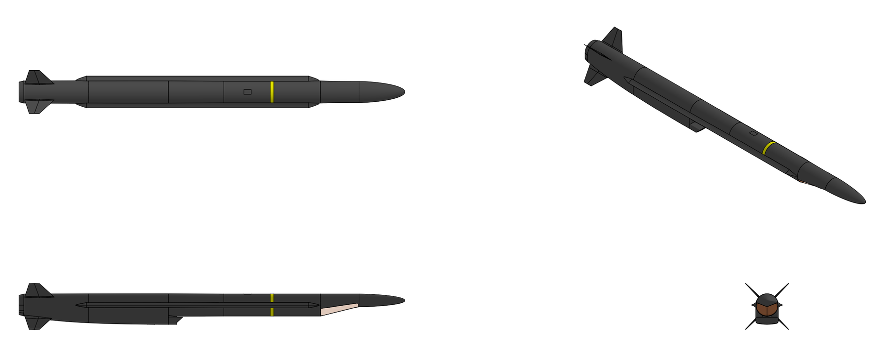
Last edited by The Technocratic Syndicalists on Sat Sep 04, 2021 2:54 pm, edited 6 times in total.
SDI AG
Arcaenian Military Factbook
Task Force Atlas
International Freedom Coalition


OOC: Call me Techno for Short
IC: The Kingdom of Arcaenia

User avatar
The Technocratic Syndicalists
Minister
 
Posts: 2350
Founded: May 27, 2015
Inoffensive Centrist Democracy

Postby The Technocratic Syndicalists » Wed Oct 21, 2020 3:31 pm

Image


GB 100


General Characteristics:
Type:
Miniature glide bomb

Launch platform:
Aircraft

Guidance:
IIR, INS/GPS, 2-way RF datalink

Physical Characteristics:
Weight:
125 kg

Length:
1.8 m

Diameter:
0.18 m

Warhead:
100 kg unitary penetrator


Performance Characteristics:
CEP:
<3 m

Range:
110 km (12,000 meter release)


Overview:
The GB 100 is a miniature precision guided standoff glide bomb designed by SDI Missile Systems. The GB 100 munition features a low-observable airframe with deployable wings, a 100 kg class penetrating blast/fragmentation warhead with multiple fuze options, and a low-cost imaging infrared (IIR) seeker which leverages embedded artificial intelligence to provide terrain-referenced autonomous navigation, scene-matching terminal guidance, and autonomous target recognition (ATR) capability, enabling full mission execution without any reliance on Global Positioning System (GPS) signals. A two-way datalink enables in-flight retargeting, battle damage assessment, and cooperative engagement with other networked munitions through AI-enabled autonomous swarming behaviors.


Design & Airframe:
The GB 100 airframe employs a low-observable square cross-section airframe with planar surfaces canted to deflect radar energy away from threat emitter locations. The rectangular faceted fuselage provides significant radar cross-section (RCS) reduction compared to a conventional cylindrical body, particularly in the nose-on and beam aspects. The airframe skin is fabricated from composite panels over an internal aluminum alloy load-bearing frame. The composite skin integrates carbon-loaded glass fiber plies that attenuate incident radar energy. The GB 100 features two high-aspect-ratio deployable wings stowed flat against the weapon body in recessed bays. Upon release, spring-loaded deployment mechanisms drive the wings outward, where they lock into the extended position. Each wing panel is a single-piece carbon fiber composite structure with a supercritical airfoil optimized for efficient subsonic glide at Mach 0.7 to Mach 0.95. The tail control section features four folding cruciform control fins that deploy after release. These all-moving fins provide pitch, yaw, and roll control authority throughout the flight envelope. Each fin is driven by a high-torque brushless DC electric actuator capable of 60°/second deflection rates. The tail fins employ a clipped delta planform with a swept leading edge to maintain favorable stall characteristics and provide adequate control power at the low dynamic pressures encountered near maximum glide range.

The GB 100 airframe is designed to minimize detection across radar, infrared, and visual bands. The faceted body, RAM composite skin, and edge-aligned planform provide significant RCS reduction. The IIR seeker window uses a low-emissivity coating that reduces the weapon’s forward-hemisphere infrared signature. With no propulsion system generating a thermal plume, the glide weapon inherently presents a low IR signature compared to powered munitions. The airframe exterior is finished in a low-reflectivity, spectrally-tailored black paint optimized to reduce visual and near-infrared contrast against sky backgrounds.


Guidance & Navigation:
The GB 100 guidance, navigation, and control system is designed from the ground up for full mission execution in GPS-denied environments. While the system can incorporate GPS when GPS signals are available, all navigation and terminal guidance functions can operate entirely on the basis of inertial navigation corrected by image-based terrain reference navigation (TRN) and terminal scene matching. The munition's imaging infrared (IIR) seeker is a dual-purpose sensor serving both the navigation (TRN) and terminal guidance (scene matching / ATR) functions. The seeker is designed for low production cost through the use of an uncooled microbolometer focal plane array (FPA) rather than a cryogenically cooled detector. The seeker employs a 640 × 512 pixel, 12 μm pixel pitch uncooled vanadium oxide (VOx) microbolometer focal plane array operating in the long wave infrared (8–14 μm) spectrum. The seeker is stabilized using a 2-axis gimbal which provides ±30°azimuth, and +10° / -60° elevation scanning capability. The seeker has a 10.5° × 8.4° full frame field of view with a 3.5° × 2.8° narrow field of view mode achievable via electronic zoom. In terrain reference navigation mode the seeker is pointed forward-down, acquiring wide-area terrain imagery for TRN feature matching. In target acquisition Mode the seeker scans the target area in a pre-programmed search pattern. ATR algorithms process each frame to detect and classify potential targets. In terminal tracking mode the seeker locks onto the designated target or aimpoint and transitions to narrow FOV for high-precision tracking. The guidance loop closes at 60 Hz with proportional navigation steering while inertial stabilization maintains track through high-g terminal maneuvers. Finally in datalink imagery mode seeker imagery is compressed and transmitted to the operator via the two-way datalink for situational awareness, target identification, and battle damage assessment

The GB 100 GNC system coupled with the seeker consists of three primary subsystems: the inertial measurement unit (IMU), the AI-enabled navigation and guidance processor, and the flight control computer. The GB 100 employs a 6-axis SDI TNS 500 tactical-grade timing and inertial measurement Unit (TIMU) which combines three MEMS (micro-electromechanical systems) quad mass gyroscopes (QMG) and three MEMS accelerometers in a low SWaP package (100 cc volume, 0.15kg mass, <2.5 watts max power consumption) package. The IMU provides strapdown inertial navigation throughout the flight with drift rates compatible with TRN update intervals. When GPS signals are available, an embedded 24 channel dual-frequency (L1/L2) SAASM (Selective Availability Anti-spoofing Module) based GPS receiver provides position and velocity aiding to the INS Kalman filter. The GB 100's embedded AI processor executes image-based terrain reference navigation using the weapon’s IIR seeker. This processor runs on a low-power, radiation-tolerant system-on-chip (SoC) featuring a multi-core ARM processor coupled with a dedicated neural processing unit (NPU) capable of 20+ TOPS (tera-operations per second) of INT8 inference throughput. During the midcourse glide phase, the IIR seeker images the terrain below and ahead of the weapon. The AI processor extracts visual features from these images and matches them against a pre-loaded terrain reference database stored in onboard flash memory. This database contains geo-registered infrared terrain imagery and elevation data for the planned route corridor and alternate routes. The matching algorithm uses a convolutional neural network (CNN) trained to recognize terrain features under varying illumination, weather, and seasonal conditions. TRN fixes are generated at a rate of 1–2 Hz, providing continuous position corrections to the INS Kalman filter with a resulting navigation accuracy of better than 30 meters circular error probable (CEP) throughout the midcourse phase, independent of GPS. The terrain reference database is mission-planned and loaded to the weapon prior to flight via the aircraft stores management interface. The database is compact, typically 64 to 256 MB depending on route length and corridor width, leveraging lossy neural compression techniques to minimize storage requirements. Multiple route corridors and branch options can be stored simultaneously to support in-flight re-routing via datalink.

Upon entering the terminal phase (typically the final 5–10 NM), the weapon transitions from area navigation mode to precision terminal guidance. The IIR seeker acquires a scene image of the target area and correlates it against a pre-loaded reference scene image or scene model. The scene matching algorithm employs a deep learning feature extraction network that is invariant to changes in scale, rotation, illumination, shadow patterns, and moderate obscuration. The scene matcher provides sub-5-meter accuracy aimpoint positioning relative to the reference scene. Reference scenes can be provided as electro-optical satellite imagery, synthetic aperture radar (SAR) imagery converted to predicted IR scene models, or previously collected IIR imagery from reconnaissance assets. The weapon can store up to 100 independent target scene packages simultaneously, supporting rapid in-flight retargeting to pre-planned alternate targets via datalink. The Seeker's ATR capability additionally enables the weapon to autonomously detect, classify, and select aimpoints on specific target types without requiring a pre-loaded reference scene. The ATR runs a multi-class object detection neural network trained on an extensive dataset of IIR imagery spanning the full range of target types including armored vehicles, mobile missile launchers, command posts, radar systems, ships, small boats, fuel storage, and structures. The network performs real-time detection and classification at 10+ frames per second, and outputs target bounding boxes, classification confidence scores, and optimal aimpoint locations for each detected target. the ATR system supports moving target engagement where the ATR maintains track on moving ground vehicles and maritime targets, providing continuous aimpoint updates to the guidance loop through impact. For maritime target engagement specialized ATR models detect and classify surface vessels, selecting vulnerable aimpoints such as the waterline or bridge structure based on vessel type.

The GB 100 incorporates a compact, low-probability-of-intercept / low-probability-of-detection (LPI/LPD) two-way datalink enabling communication between the weapon and the launch aircraft, ground control stations, or other networked assets. The datalink is used for in-flight target update and retargeting, weapon status telemetry, seeker imagery downlink, mission abort and electronic safing commands, and inter-munition communication for cooperative engagements. The datalink operates in the Ku-band and employs spread-spectrum / frequency-hopping LPI/LPD waveforms. Uplink data rate is 256 kbps (commands, target updates) while downlink data rate is 2 Mbps (imagery, telemetry, ATR results). The datalink uses flush-mounted conformal array mounted on the top and bottom of the munition with 80 NM line-of-sight to aircraft relay range and > 20 dB jam resistance. Uplink functions include in-flight target coordinate update and retargeting to pre-loaded alternate targets, new target designation with coordinates and/or reference scene upload, ATR target class priority reprogramming, fuze mode and height-of-burst reprogramming, mission abort with electronic safing command, and cooperative engagement task assignments. Downlink functions include weapon health and status telemetry (position, velocity, time-to-impact), compressed IIR seeker video for operator situational awareness, ATR detection results with classification and confidence data, terminal imagery for battle damage indication (BDI) imagery prior to impact, and inter-munition mesh network relay for cooperative engagements. When multiple The GB 100 munitions are launched against targets in a common operating area, the weapons establish an encrypted mesh network via their datalinks and execute cooperative behaviors governed by onboard AI algorithms. This cooperative engagement capability enables mission effects that are not achievable with individually targeted weapons. The onboard AI cooperative engagement algorithms supports various autonomous swarming behaviors including collaborative search, where multiple weapons are assigned a search area and autonomously distribute search sectors among themselves to maximize area coverage rate. When one weapon detects a target, it shares target data with the swarm and the swarm collaboratively refines the target location and classification. When multiple weapons detect multiple targets in a target area, the swarm AI autonomously assigns weapons to targets to maximize overall engagement effectiveness, avoiding redundant engagement of the same target while ensuring all identified targets are engaged. Simultaneous Time-on-Target (STOT) is also supported where the swarm coordinates weapon velocities and flight paths to achieve near-simultaneous impact on one or multiple targets. STOT attacks from multiple approach vectors to overwhelm point defense systems and maximize the probability of target destruction. The system also supports a maritime swarm attack mode, a specialized maritime engagement mode that uses algorithms to coordinate the swarm to identify and classify naval targets, assign weapons to specific vessels based on priority, and execute multi-axis attacks designed to overwhelm ship-based close-in weapon systems (CIWS). All swarming modes feature dynamic tetargeting, If a target is destroyed or abandoned, surviving weapons autonomously reallocate to remaining or newly detected targets based on updated priorities without operator intervention. The inter-munition communication network uses a decentralized mesh topology with no single point of failure. Each weapon operates as both a node and a relay, extending the effective communication range of the swarm. The network protocol supports dynamic joining and departure of nodes as weapons are launched, expend, or are lost. All inter-munition communications are encrypted and frequency-hopping to resist electronic warfare intercept and jamming.


Warhead:
The GB 100 employs a 100 kilogram class penetrating blast/fragmentation warhead optimized to defeat a broad range of target types. The warhead casing is fabricated from high-strength steel alloy with controlled fragmentation scoring on the inner surface, producing a predictable, optimized fragment pattern upon detonation. The warhead features a hardened steel nose cap with an ogive profile designed to survive impact with reinforced concrete and light earthen cover at terminal velocities up to Mach 1.0. The warhead case is filled with 20 kilograms of enhanced blast thermobaric explosive (50% HMX, 30% Al powder, 20% PCP/TMETN energetic binder/plasticizer) which produces a sustained high-pressure blast pulse significantly exceeding that of equivalent-weight conventional explosives in confined spaces. The warhead is fitted with a base mounted hard target smart fuze (HTSF) containing a precision MEMS accelerometer and micro-controller which features void sensing, layer counting, depth of penetration, and time time delay after impact fuzing modes. The detonator is entirely electronic with no moving parts and uses an exploding foil initiator (EFI) detonator to initiate the main explosive charge. With a terminal impact velocity of near Mach 1.0 when used with a high altitude release the warhead is capable of penetrating up to 2.0 meters of 34 MPa (5,000 psi) reinforced concrete before exploding. The fuze also supports impact and proximity / height-of-burst (HOB) fuzing modes effective against unreinforced structures and groups of soft targets
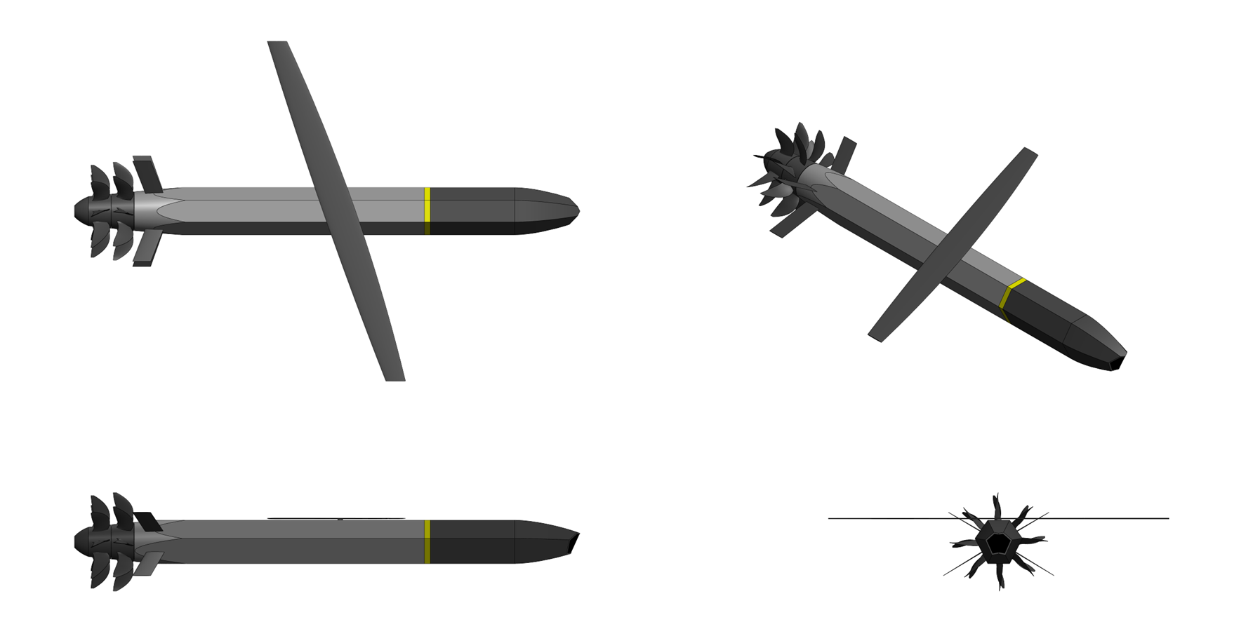

Flight Sequence:
The GB 100 mission profile consists of four phases: separation and wing deployment, midcourse glide with terrain reference navigation, terminal acquisition, and terminal engagement. The weapon is released from the aircraft at aircraft cruising speed and altitude. Within 0.5 seconds of release, the wings and tail fins deploy and lock. The weapon enters a controlled glide, managing its energy to maximize range to the target area. The navigation processor continuously corrects the INS solution using IIR-based TRN throughout the midcourse phase. During the midcourse phase the autopilot also incorporates wind estimation algorithms using air data and INS measurements to compensate for crosswinds during the glide phase. Upon approaching the target area, the weapon transitions to terminal acquisition mode. The seeker scans for the target using either pre-loaded scene matching references or ATR detection algorithms. Once the target is acquired and positively identified, the weapon enters terminal engagement, executing the selected attack profile (shallow glide, steep dive, or lofted trajectory) and impact conditions (fuze mode, angle of attack, velocity vector).
Last edited by The Technocratic Syndicalists on Sun May 03, 2026 8:11 pm, edited 11 times in total.
SDI AG
Arcaenian Military Factbook
Task Force Atlas
International Freedom Coalition


OOC: Call me Techno for Short
IC: The Kingdom of Arcaenia

Next

Advertisement

Remove ads

Return to Global Economics and Trade

Who is online

Users browsing this forum: No registered users

Advertisement

Remove ads