RM220
- Name: SDI RM220
- Type: Adaptive Cycle Afterburning Turbofan
- Length: 5,080 mm
- Diameter: 1,170 mm
- Dry Weight: 1,950 kg
- Bypass Ratio: 0.2 to 1.20
- Compressor: Two stage fan, core driven fan stage (CDFS), five stage high pressure compressor
- Combustor: Double-dome annular
- Turbine: single stage HPT, counter rotating single two LPT
- Maximum Thrust: 163 kN (dry), 214 kN (with afterburner)
- Overall Pressure ratio: 38:1
- Air mass flow : 150 kg/s
- Turbine inlet temperature: 2,090 °C intermediate, 2,260 °C combat
- Specific fuel consumption: 25 g/Kn-s (dry), 45 g/Kn-s (afterburning)
- Thrust-to-Weight Ratio: 9.0:1 (dry), 11.6:1 (with afterburner)
Overview:
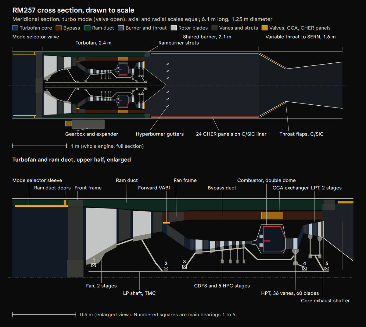
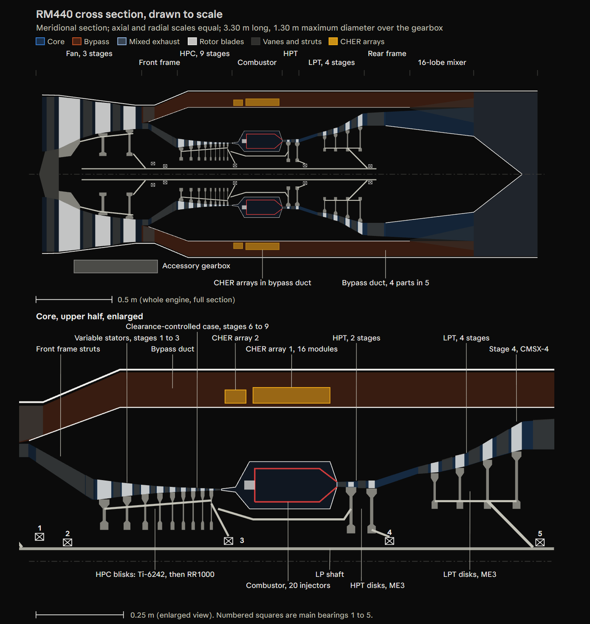
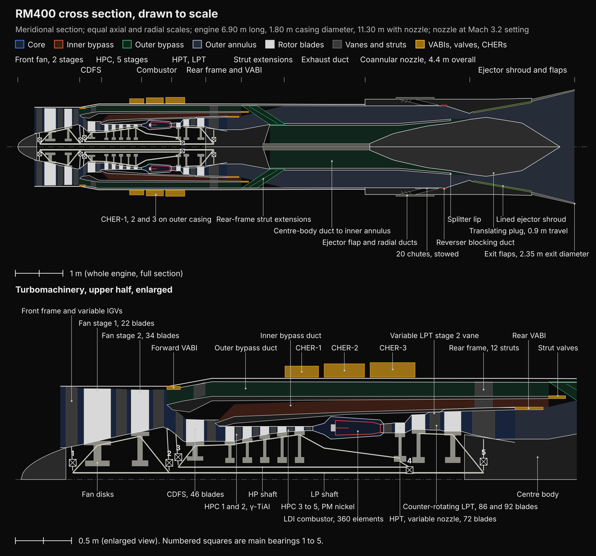
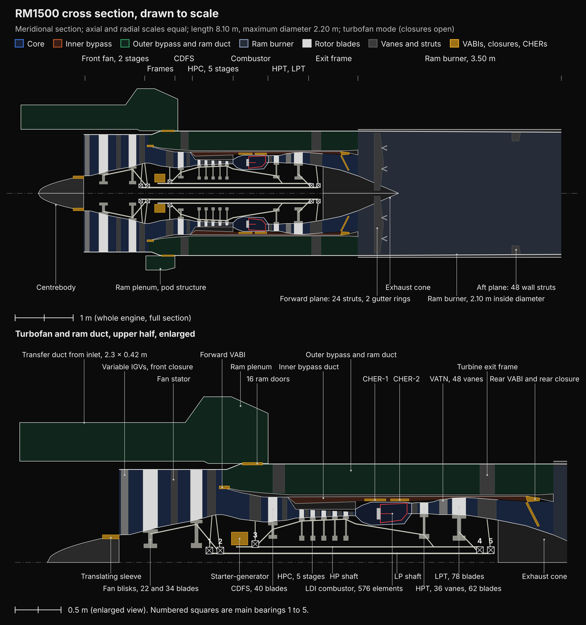
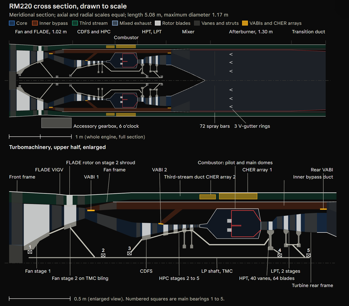
The SDI RM220 is three stream adaptive cycle afterburning turbofan engine developed for SDI's AEJ 36 Seraph air superiority fighter. The RM220B is a two-spool, three-stream, adaptive cycle afterburning turbofan Wwith a low pressure spool consisting of two stage fan and single stage low pressure turbine and a high pressure spool consisting of five stage high pressure compressor with core driven fan stage (CDFS) and a single stage high pressure turbine. The low pressure (LP) spool consists of a FLADE stage and a two stage fan driven by a two stage low-pressure turbine (LPT). The FLADE stage is formed by extending the second-stage fan blades outward into an annular outer duct whose flow is set by the variable inlet guide vanes (VIGV). The high-pressure (HP) spool consists of a core-driven fan stage (CDFS), four further high-pressure compressor (HPC) stages, and a single stage high-pressure turbine (HPT). The HP and LP spools rotate in opposite directions which reduces the turning and therefore the loss of the first-stage LPT vanes that receive the swirl leaving the HPT blades. The core flow passes from the HPC to a double dome lean premixed prevaporized (LPP) combustor and then through the HPT and LPT. The inner bypass flow passes between the core and the third stream, and is reintroduced into the core exhaust by a rear variable area bypass injector (VABI) ahead of a mixed-flow afterburner. The third stream does not pass through the afterburner and is ducted along the outer casing and discharged around the nozzle and through the exhaust trench of the airframe where it cools the nozzle flaps and the trench surfaces. The hot section is cooled by fuel. Two catalytic heat exchanger/reactor (CHER) arrays mounted in the outer bypass duct around the combustor case cool all of the HPT cooling air by 350 K with J9 fuel before it reaches the vanes, blades and disk The control is a distributed engine control (DEC) with six engine mounted smart nodes.The engine has seven variable elements including the FLADE variable inlet guide vanes (VIGV), VABI 1, VABI 2, the HPC variable vanes, the variable-area LPT nozzle, the rear VABI and the nozzle throat and exit areas. Together they allow the bypass ratio, the fan operating point and the third-stream flow to be set independently of the spool speeds. The control places the engine in one of three modes. Maximum power mode: VABI 2 is closed, VABI 1 is set for an inner bypass ratio of 0.20 to 0.55, and the FLADE VIGV pass 3 to 8% of the total airflow, the minimum needed for nozzle cooling. This mode is used for takeoff, acceleration, combat and supercruise. Part power mode: VABI 1 and VABI 2 are opened and the LPT nozzle area is increased. The inner bypass ratio rises to 1.20 and the third-stream flow to 30%. The specific fuel consumption at Mach 0.85 and 12,000 m is 25.1 g/(kN·s) Flow holding mode: Between 75 and 100% of maximum dry thrust the FLADE VIGV open as the core is throttled, so that the engine airflow stays within 5% of the inlet capture flow. Inlet spillage drag is about halved, and most of each supercruise leg is flown in this mode. Mode transitions are made at constant thrust, with the fan held at least 15% from stall
Fan & HPC
The fan module consists of the front frame, the FLADE inlet and its variable inlet guide vanes, two fan stages, the FLADE stage carried on the second-stage blades, the fan stators and VABI 1. The module is a separate maintenance unit, 1.02 m long, with a mass of 290 kg including the fan frame. The front frame is a one-piece investment casting of Ti-6Al-4V with an inner hub, 12 radial struts and two concentric outer rings. The inner ring at 0.497 m radius forms the outer wall of the fan inlet, and the outer ring at 0.585 m radius forms the outer wall of the FLADE inlet annulus. The struts are 30 mm thick at 10% thickness-to-chord and carry the No. 1 bearing load to the forward mount ring. Four struts contain the bearing oil supply and scavenge lines, and all 12 are anti-iced by scavenge oil at about 120 °C routed through cored passages behind the leading edge. The fan face has no inlet guide vanes. The aerodynamic interface plane is the front flange, 0.12 m ahead of the stage 1 leading edge at the tip. The fan accepts a circumferential distortion intensity of 0.10 at this plane, the level produced by the S-duct of the AEJ 36 at high angle of attack while holding its 15% stall margin. The stage 1 rotor has 18 hollow, wide-chord blades with a tip diameter of 0.970 m and an inlet hub-to-tip radius ratio of 0.284. The annulus passes 140.6 kg/s at sea level static conditions at an inlet axial Mach number of 0.62, a specific flow of 207 kg/s per m² of annulus. At the maximum LP speed of 10,300 rpm the tip speed is 523 m/s and the inlet relative Mach number at the tip is 1.72. The stage pressure ratio is 2.40 at an adiabatic efficiency of 0.860, and the rotor tip diffusion factor is 0.47. Each blade is 347 mm long at the leading edge, with chords of 215 mm at the tip, 198 mm at mid-span and 182 mm at the root, which gives an aspect ratio of 1.75 and solidities of 1.27 at the tip and 3.7 at the hub. The tip sections are precompression airfoils with a maximum thickness of 2.5% of chord and a sharp leading edge of 0.25 mm radius, which places the passage shock near the throat and limits the shock loss at the high relative Mach number. The root sections are double circular arc with 7% thickness. The blade has no part-span shroud. The blades are Ti-6Al-2Sn-4Zr-2Mo (Ti-6242) and are made by superplastic forming and diffusion bonding of three sheets. The two outer skins, 2.8 mm thick at the root and 1.2 mm at the tip, are bonded to an internal Warren-truss core of 0.8 mm sheet, so that 46% of the airfoil volume is hollow. The leading edge is solid for the first 8% of chord to resist bird and foreign object damage, and the hollow blade weighs 2.9 kg against 5.4 kg for a solid blade of the same shape. The blades are linear friction welded to a bladed ring (bling) whose hoop load is carried by an embedded titanium matrix composite (TMC) ring of SCS-6 silicon carbide monofilament in a Ti-6242 matrix with 35% SiC fiber by volume. The TMC core is 38 mm wide and 22 mm deep, fully encapsulated in monolithic Ti-6242, and has a hoop modulus of 230 GPa and a tensile strength of 1,700 MPa. The bling replaces a disk with a deep bore, and the stage 1 rotor weighs 74 kg including blades, which is about 30% less than an equivalent bladed disk. The stage 1 stator has 46 vanes of Ti-6Al-4V with a chord of 82 mm and an aspect ratio of 2.0. The vanes are welded into inner and outer rings and form a non-structural assembly; the fan frame carries the loads. The stator turns the flow to axial with an exit Mach number of 0.48. The stage 2 rotor has 38 blades with a tip radius of 0.462 m and a hub radius of 0.309 m at inlet. The blade height is 153 mm and the mean chord 106 mm, an aspect ratio of 1.45. The tip speed is 498 m/s and the stage pressure ratio 2.10 at an adiabatic efficiency of 0.865. The blades are hollow Ti-6242, made by diffusion bonding two machined halves with a cavity of 30% of the airfoil volume, and are linear friction welded to a TMC-reinforced bling of the same construction as stage 1.The FLADE stage is a row of 72 short blades mounted on an outer ring that forms the tip shroud of the stage 2 blades. The ring is Ti-6242 with a TMC hoop core and runs at a radius of 0.470 m and divides the stage 2 passage from the FLADE duct and carries the FLADE blades through the stage 2 blades to the bling. Each stage 2 blade tip is diffusion bonded into a socket in the ring so that the 38 blades and the ring form one rotor. The FLADE blades are integral with the ring, machined from a ring forging, and extend from 0.475 m to 0.555 m radius with a chord of 45 mm. The FLADE tip speed is 599 m/s with a pressure ratio 1.70 at an adiabatic efficiency of 0.84. The FLADE duct inlet is set by 36 Ti-6Al-4V VIGV with a chord of 70 mm. The VIGV rotate from 0° to 80° on spindles in bronze lined bushings, and vary the third stream flow from 3% to 30% of the total airflow at constant LP speed. All 36 vanes are linked by levers to one unison ring which is moved by a single electromechanical actuator with a stroke of 64 mm and a force of 9 kN. The 60 FLADE exit vanes are fixed and also form the forward struts of the outer duct. The stage 2 stator has 64 Ti-6Al-4V vanes with a chord of 52 mm welded to inner and outer rings. Its exit hub-to-tip ratio is 0.81 and its exit Mach number 0.45. The two blings are joined by an electron beam welded Ti-6242 drum and the rotor is bolted at its rear to the LP shaft with 36 bolts of 10 mm diameter. Stage 1 runs with a cold tip clearance of 1.0 mm and stage 2 of 0.8 mm over abradable aluminium-silicon polyester rub strips. The first flexural, first torsional and two-stripe modes of the stage 1 blade are placed clear of the 1, 2 and 3 per revolution excitations between 80 and 105% of maximum speed with at least 10% margin. Each blade is checked for flutter at the corner of the operating map with a reduced frequency of at least 0.35 in the first torsional mode. The fan case is Ti-6242 with an integral containment belt 9 mm thick over the stage 1 tip, which contains a released stage 1 blade at 105% of maximum speed. the forward VABI (VABI 1 is a translating ring at the splitter behind the stage 2 stator. Closed it directs all of the stage 2 flow into the CDFS while open it diverts up to 50% of the stage 2 flow into the inner bypass duct, which is the main means of varying the bypass ratio. The ring is Ti-6242, 0.36 m in mean radius, and translates 42 mm on 12 rollers driven by two synchronized electromechanical actuators, each sized to complete the stroke alone in 1.2 s.
The HP spool compressor consists of the CDFS and four HPC stages, numbered 2 to 5, which together raise the pressure of the core flow by a ratio of 7.75 at sea level static conditions. With the fan pressure ratio of 5.04 this gives the overall pressure ratio of 38. The compressor is designed around a compressor exit temperature limit of 927 °C. The CDFS is the first stage of the HP spool and receives the stage 2 fan flow not diverted by VABI 1, 140.6 kg/s at sea level static conditions in the maximum power mode, and raises its pressure by 1.60 at an adiabatic efficiency of 0.87. Its 36 blades have a tip radius of 0.330 m, a height of 121 mm, a mean chord of 75 mm and an aspect ratio of 1.6. The tip speed is 505 m/s at the maximum HP speed of 14,600 rpm. The CDFS is preceded by 40 variable inlet guide vanes and followed by 52 variable stator vanes. VABI 2 is a translating splitter ring behind the CDFS stator at a radius of 0.300 m and divides the CDFS exit flow between the HPC and the CDFS bypass duct which joins the inner bypass duct. It is closed in the maximum power mode and opened in the part power mode, and is driven by two electromechanical actuators of the same type as VABI 1. The HPC has a constant tip radius of 0.315 m and a rising hub designed so that mean blade speed increases from 436 m/s at stage 2 to 462 m/s at stage 5 and the rear stages which carry the highest temperatures carry the least aerodynamic loading. The tip speed is 482 m/s at maximum HP speed. The inlet axial Mach number falls from 0.50 at stage 2 to 0.38 at stage 5 and 0.30 at the exit guide vanes. The stage pressure ratios are 1.56, 1.51, 1.46 and 1.41, and the polytropic efficiency of the four HPC stages is 0.895. Stage 2 is transonic at the tip, with an inlet relative Mach number of 1.18, and has a precompression tip section. Stages 3 to 5 are subsonic, with controlled-diffusion airfoils whose diffusion factors are 0.45, 0.43 and 0.40 at mid-span. The blades are low in aspect ratio, falling from 1.3 at stage 2 to 1.0 at stage 5, for tolerance of foreign object and stall damage. The stage 5 blades are 25 mm tall, and the tip clearance of 0.25 mm at the running condition is 1.0% of the blade height. The CDFS inlet guide vanes, the CDFS stator and the stage 2 stator are variable. They are set by two unison-ring systems driven from one torque shaft along the case by two electromechanical actuators, each able to drive all three rows alone. The schedule is set by the engine control against corrected HP speed, and the HPC stall margin of 12% is estimated by the on-board engine model rather than inferred from a fixed schedule. A handling bleed at stage 3, 4% of core flow, discharges into the inner bypass duct during starts and rapid decelerations and is closed in all steady operation. The stage exit temperatures at Mach 2.5 and 20,000 m are 451 °C at the CDFS, 548 °C at stage 2, 658 °C at stage 3, 782 °C at stage 4 and 927 °C at stage 5. the CDFS and second stage blades are cast Ti-48Al-2Cr-2Nb gamma titanium aluminide with half the density of nickel alloys and a limit of 750 °C, linear friction welded to a Ti-6242 transition stub on blings with SCS-6/Ti-6242 TMC hoop cores. The rims of the blings run at 470 and 560 °C. The third stage blades are forged Ti-43.5Al-4Nb-1Mo-0.1B (TNM) gamma titanium aluminide whose higher strength suits the higher loading of the stage. The bling has a core of SCS-6 fibre in an orthorhombic Ti-22Al-23Nb matrix which retains its strength to about 700 °C. The fourth and fifth stage airfoils are single-crystal CMSX-4 linear friction welded to rims powder-metallurgy (PM) formed RR1000 alloy to form dual-alloy blisks. Each rim carries a tungsten fiber reinforced superalloy (TFRS) hoop ring with W-Re-Hf-C wire at 40% by volume in a cobalt-free nickel matrix. The ring has a density-corrected stress-rupture strength about 2.5 times that of the strongest monolithic disk alloys at 1,100 ° and carries the hoop load of the rim. The ring is fully encapsulated in the disk alloy so that the fiber is sheilded from oxidizing gas above 980 °C. The stage 5 rim runs at 777 °C with cooled bore air. The titanium front rotor comprising the CDFS and second and third stages is one inertia-welded assembly. The nickel rear rotor, comprising the fourth and fifth stages and the compressor discharge seal is a second inertia welded assembly. The two are joined at one bolted flange of 30 bolts of 8 mm diameter between stages 3 and 4. The rear rotor is joined to the HPT shaft by a curvic coupling. The bores of stages 4 and 5 are cooled by air from the second catalytic heat exchanger/reactor (CHER) array at about 375 °C. The stators of the CDFS and stages 2 and 3 are gamma TiAl and stages 4 and 5 and the exit guide vanes are cast Mar-M-247 vane segments with six vanes to a segment. The front compressor case is SCS-6/Beta-21S TMC while the rear case, from stage 4 aft, is Haynes 282 and has an inner liner of abradable nickel honeycomb filled with yttria-stabilized zirconia over each rotor. The exit guide vanes remove the swirl at an exit Mach number of 0.30. A pre-diffuser of area ratio 1.6 then reduces the velocity before a short dump into the combustor case, with a total pressure loss of 1.5%. The engine provides no customer bleed air. Three internal offtakes are taken including stage 4 air, 1.0% of core flow, that cools the first stage LPT vanes, stage 4 air, 1.5% of core flow, cooled in CHER array 2 that cools the stage 4 and 5 disk bores and pressurizes the bearing buffer system, and compressor exit air, 5.9% of core flow, cooled in CHER array 1 that cools the HPT vanes, blades and disk.
Combustor
The combustor is an annular, double-dome, lean premixed prevaporized (LPP) design with ceramic matrix composite liners that burns at a combustor exit temperature of 2,093 °C at the intermediate rating and 2,260 °C at the combat rating with an inlet temperature of up to 927 °C and keeps NOx emissions low by burning lean throughout. The combustor occupies the annulus between radii of 0.215 m and 0.430 m inside the combustor case, and is 0.24 m long from the dome face to the HPT vane leading edge. The two domes are stacked radially. The outer pilot dome, centred at a radius of 0.345 m, has 30 swirl cups. The inner main dome, centred at 0.270 m, has 30 pairs of premixing ducts, 60 in all, arranged in three circumferential groups of ten pairs that are staged in one group at a time. A cenerbody ring between the domes shields the inner liner from the pilot flame and carries the spent liner impingement air into the primary zone. Nearly all of the combustor air passes through the domes. At the intermediate rating the overall equivalence ratio is 0.59 at sea level static conditions and 0.58 in supercruise, rising to 0.64 at the combat rating. The air entering the combustor case is divided into 63% through the main premixers, 18% through the pilot swirl cups, 9% as liner impingement air, which then enters the primary zone through the centrebody, and 1.5% through the nozzle platform purge slots. The remaining 8.5% of core flow leaves the case as turbine cooling air. No air is used for dilution. Each pilot swirl cup has a pressure-atomizing simplex injector surrounded by two corotating radial swirlers with vane angles of 45° and 60°. The pilot burns liquid J9 drawn from the fuel system upstream of the CHER arrays at below 360 °C so that it is independent of the CHER circuit and operates alone from light-off to about 30% of maximum dry thrust at a local equivalence ratio of up to 0.85 and remains lit at all powers at a local equivalence ratio of about 0.55 to anchor the main flame. Two 12 J capacitor discharge surface gap igniters at the 4 and 8 o'clock position, are fitted in the pilot dome. Ground starts and relights to 13,700 m are made on the pilot alone. Each premixer is a 22 mm internal diameter duct 30 mm in length with a 45° axial vane swirler of eight vanes at its entrance and a fuel spoke behind the swirler. The spoke carries six 0.35 mm diameter orifices on each side which inject the main fuel across the airflow. The axial velocity in the duct is about 120 m/ and the residence time from fuel injection to the duct exit is 0.25 ms or less. The duct walls are smooth and convergent by 6% in area and the duct contains no step, bluff body or recirculation zone on which a flame could stabilize. The main dome receives J9 that has passed through the oil cooler, the fuel cooled nozzle ramp panels and both CHER arrays. In supercruise this fuel reaches 600 to 640 °C at 8 to 10 MPa, above its critical point, and is 15 to 24% converted by catalytic dehydrogenation so that it contains 1.1% hydrogen by mass and enters the premixer as a dense gas, and no droplets have to evaporate. The hydrogen widens the lean stability limit of the main dome by about 0.05 in equivalence ratio. At high power, when the CHER outlet is below 360 °C, the main fuel is a compressed liquid and is atomized by the same orifices at a pressure drop of 3.5 MPa.
The inner and outer liners, the centerbody ring and the dome heat shields are SiC/SiC ceramic matrix composite (CMC) made from eight plies of a five harness satin weave of Hi-Nicalon Type S fibre with a boron nitride interface coating and a melt-infiltrated silicon carbide matrix. The liner wall is 2.0 mm thick. Its hot face carries an environmental barrier coating (EBC) of ytterbium disilicate, 0.15 mm thick, on a hafnia-silicon bond coat that is stable to about 1,500 °C. The EBC surface temperature is held below 1,427 °C and the CMC substrate below 1,317 °C. The liners are cooled only on the back face. A perforated nickel impingement sheet spaced 2.5 mm behind each liner, directs jets of 1.0 mm diameter at a pitch of 6 mm onto the cold face and the spent air passes forward and enters the primary zone through the centerbody. There are no film cooling holes which would weaken the composite and initiate EBC spallation. Each liner is held to the nickel dome structure by 30 radial pins at its forward end and is free to slide axially at its aft end in a spring finger seal so that the different thermal expansion of the CMC and the nickel structure is accommodated without load. The principal hazard is flashback and autoignition in the premixers, at a compressor exit temperature of 927 °C the autoignition delay of the mixture is short and the hydrogen in the main fuel shortens it further. The 0.25 ms residence time keeps the mixture within the duct for less than a third of the shortest delay at the supercruise condition. The combustor node of the engine control reads four high-response dynamic pressure transducers in the case and an ultraviolet photodiode viewing the exit of each premixer group. On an indication of flashback or of a combustion instability above 2% of the static pressure, the node destages the affected group within 20 ms and transfers its fuel to the pilot. The exit temperature distribution is controlled to a pattern factor of 0.11 which places the peak gas temperature at the HPT vanes at 2,227 °C at the intermediate rating and 2,407 °C at the combat rating. The radial profile is peaked at mid-span to reduce the temperature at the vane platforms and the blade tips. The pattern factor is held when a group is staged out as the pilot dome then carries part of its load. The combustor case is Haynes 282, 6 mm thick, and is designed to a burst pressure of 12 MPa. It carries 24 offtake bosses for CHER array 1, 6 bosses for CHER array 2, the two igniter ports, four dynamic pressure ports and six borescope ports. The combustor, diffuser and case have a mass of 75 kg.
High Pressure & Low Pressure Turbines
The HPT is a single stage cooled turbine with SiC/SiC ceramic matrix composite vanes and blades on a nickel disks and drives the CDFS and the HPC, absorbing 51.8 MW at sea level static conditions, and has an expansion ratio of 3.9 at an efficiency of 0.885. The vane throat area is 0.0353 m², which sets the core flow of the engine. The vanes turn the flow to 74° from axial at the exit, and the annulus at the vane exit is 0.128 m², with a mean radius of 0.305 m and a height of 67 mm. The blade tip speed is 517 m/s and the mean blade speed 466 m/s at 14,600 rpm, which gives a stage loading coefficient (Δh/U²) of 2.10, a flow coefficient of 0.45 and a mean reaction of 0.40. The product of annulus area and the square of speed (AN²) is 27.3 × 10⁶ m²·rpm². The blades leave about 15° of swirl against the direction of HP rotation, which the counter-rotating LPT uses with less turning in its first vane row. The 40 vanes have a chord of 62 mm and a solidity of 1.30 at mid-span. The 64 blades have a chord of 34 mm, a height of 71 mm and an aspect ratio of 2.1, with a mid-span solidity of 1.14 and a Zweifel coefficient of 0.92. The radial profile of the combustor exit (Section 4.5) is peaked at mid-span, and the blade is stacked with 4° of lean to reduce the secondary loss at the hub. The vanes are SiC/SiC, made from Hi-Nicalon Type S fiber plies with a boron nitride interface and a melt infiltrated matri, laid up around a hollow mandrel to a wall thickness of 1.6 mm. The external surface carries a two layer rare-earth silicate EBC, 0.20 mm thick. Each vane is hollow and contains a sheet-metal impingement insert of Haynes 230, which directs coolant onto the inside of the leading edge and the pressure and suction walls through holes of 0.5 mm diameter. The spent air leaves through a single row of 11 film holes at the leading edge and through a slot in the trailing edge. The vanes are held between inner and outer bands of cast Mar-M-509 cobalt alloy. Each vane is located by a nickel spar that passes through the insert and carries the aerodynamic load to the outer band, so that the composite carries only its own pressure loading. Woven ceramic rope seals between the vane platforms and the bands accommodate the difference in thermal expansion. The design max temperatures are an EBC surface temperature of 1,427 °C and a CMC substrate temperature of 1,317 °C. The blades are solid root SiC/SiC laminates with a three pass serpentine internal cooling passage formed by fugitive inserts during layup. The coolant enters at the root, passes up the leading edge, down the mid-chord and up the trailing edge, and leaves through a trailing-edge slot. There are no film holes. The blade has a mass of 0.11 kg, one third of a nickel blade of the same size, and its centrifugal pull at maximum speed is 22 kN. The design allowable is an EBC surface temperature of 1,377 °C, 50 °C below the vane allowable, because of the centrifugal stress in the composite.
Each blade has a single-lobe dovetail, which is wrapped in a compliant layer of nickel foil 0.25 mm thick and seated in a broached slot in the disk rim. The compliant layer spreads the contact load and prevents fretting of the composite. A cast Mar-M-247 platform damper under each pair of blades damps the first flexural mode and seals the gap between platforms. The vanes and blades are cooled with compressor exit air that has been cooled by fuel in CHER array 1 to 577 °C at Mach 2.5 and 20,000 m. The cooling effectiveness required at that condition is 0.48 at the vanes and 0.44 at the blades at the intermediate rating and 0.531 and 0.49 at the combat rating against 0.55 attainable in the composite with impingement cooling. The vane cooling flow is 3.2% and the blade cooling flow 2.7% of core flow. The blades receive their air through 24 pre-swirl nozzles at a radius of 0.205 m which accelerate it to the rotor speed at that radius so that it enters the disk with little relative velocity. The relative total temperature of the blade coolant is 38 °C below that of air delivered through plain holes. The vanes have no pressure rise and the CHER array and its ducts lose about 7% of compressor exit pressure. An electrically driven boost compressor therefore raises the vane coolant pressure by a ratio of 1.08, to 3% above the gas pressure at the vane leading edge. The HPT disk is a dual-microstructure forging made from ME3 powder metallurgy nickel alloy with a grain size of about 10 µm at the bore for low cycle fatigue strength and about 45 µm at the rim for creep strength. A TFRS hoop ring of W-Re-Hf-C wire encapsulated in the rim allows a rim temperature of 827 °C. The bore and rim are cooled by CHER air and the disk is bolted to the HPT shaft which is joined to the compressor rear rotor by a curvic coupling. The blade outer air seal consists of 36 SiC/SiC shroud segments carried on a Haynes 282 support ring. The running tip clearance is held at 0.40 mm in supercruise by an active clearance control system which blows inner bypass air at a modulated flow onto the support ring, the valve iset by the engine control from the estimated rotor and case growth.
The LPT has two stages and drives the fan and the FLADE stage, absorbing 28.7 MW at sea level static conditions. the LPT rotates opposite to the HPT so that its first vane row receives the swirl leaving the HPT blades with only 62° of turning. The expansion ratio is 1.85 at sea level static conditions and the efficiency 0.915. The flow path has a constant mean radius of 0.330 m. The annulus height rises from 99 mm at the first vane inlet to 144 mm at the second blade exit, and the exit hub-to-tip ratio is 0.64. At the maximum LP speed of 10,300 rpm the mean blade speed is 356 m/s and the stage loading coefficient is 0.99 in each stage, which is light and is chosen for efficiency and for low blade stress in the composite. The exit Mach number is 0.50 with less than 5° of swirl. The first stage vanes are also the variable LPT nozzle. Each of the 52 SiC/SiC vanes is carried on a hollow Haynes 230 alloy trunnion cooled internally and rotates through ±5°, varying the LPT flow area by ±12%. The vanes are driven by a unison ring outside the case through levers and a single electromechanical actuator with the engine control using them to set the work split between the spools in the adaptive cycle modes. The vanes are cooled with stage 4 compressor air, 1.0% of core flow, with the LPT inlet temperature reaching 1,567 °C at Mach 2.5. The first stage blades see a relative gas temperature of about 1,460 °C in supercruise and are cooled through a single radial passage with 0.8% of core flow taken from stage 4 air. The second stage vanes and blades see 1,340 °C and are uncooled. All airfoils are SiC/SiC with rare earth silicate EBC and the blades at one third of the density of nickel blades reduce the rim loads enough for the disks to run without bore cooling. The disks are ME3 with TFRS rim rings and the rims are purged with stage 4 air at 0.3% of core flow. The blades have integral tip shrouds with two knife edge seals each running against abradable honeycomb lands. The turbine rear frame has ten Haynes 28 alloy struts inside SiC/SiC fairings which remove the residual swirl before the mixer. It also carries the No. 5 roller bearing, and the No. 4 intershaft roller bearing supports the rear of the HP spool on the LP shaft.
All of the air that cools the HPT vanes, blades and disk is cooled by fuel in two catalytic heat exchanger/reactor (CHER) arrays, and the heat is returned to the combustor in the fuel. The system cools the turbine air by 350 °C, and it varies the fraction of fuel passing through the arrays so that the fuel can reach the temperature at which J9 decomposes endothermically. The system mass is 125 kg per engine. The fuel node of the engine control splits the metered fuel into a liquid stream, for the pilot dome and the afterburner, and a coolant stream. The coolant stream passes in turn through the engine oil cooler, the heat pump condenser of the aircraft thermal management system, the fuel-cooled nozzle ramp panels, CHER array 2 and CHER array 1, and is then injected into the main dome premixers as a supercritical fluid. CHER array 1 consists of 24 modules mounted around the combustor case in the third stream duct. Each module is a double wall counterflow plate-fin unit constructed from Haynes 230, 310 mm long, 120 mm wide and 60 mm deep. The air side has 0.10 mm sheet offset strip fins at 1.6 mm pitch. The fuel side has etched microchannels 0.5 mm wide and 0.3 mm deep coated with a platinum dehydrogenation catalyst on a zeolite washcoat. Compressor exit air, 5.9% of core flow, enters through the combustor case bosses, is cooled from 927 °C to 577 °C at Mach 2.5 and 20,000 m, and returns to the vane and blade feeds. CHER array 2 consists of six smaller modules of the same construction and cools stage 4 air, 1.5% of core flow, to 377 °C for the stage 4 and 5 disk bores and the bearing buffer system. J9 fuel is rich in cycloalkanes of the decalin and tetralin type. Above 480 °C in the presence of the catalyst these give up hydrogen in an endothermic reaction that absorbs about 450 kJ/kg at 25% conversion. The products have a heating value about 1.1% higher than the original fuel so that the heat removed from the cooling air is returned to the cycle as chemical energy. The coolant fraction is scheduled by the engine control against the heat load. At high power, where the fuel flow is large compared with the heat load, 80% of the fuel passes through the CHER arrays and the coolant stream stays below 360 °C. In supercruise where the fuel flow is small the coolant fraction is reduced to between 40 and 55% and the stream reaches 600 to 640 °C with 15 to 24% conversion. The arrays and their ducts lose about 7% of compressor exit pressure, a single stage centrifugal boost compressor therefore raises the vane coolant pressure by a ratio of 1.08 to 3% above the gas pressure at the vane leading edge. Its titanium impeller, 110 mm in diameter, runs at up to 62,000 rpm on active magnetic bearings and is driven by a 120 kW permanent magnet motor from the ±270 V DC system of the aircraft. It absorbs 46 kW at Mach 2.5 and 20,000 m, 56 kW at the combat rating and up to 111 kW at Mach 0.9 at sea level with its speed set by the fuel and CHER node. The unit has a mass of 25 kg. A fuel leak into the turbine cooling air would ignite inside the engine. Each module of CHER array 1 therefore has two walls between the fuel and the air, with a nitrogen-purged interspace whose pressure is monitored by the engine control. On a detected leak the control closes the coolant isolation valve within 50 ms, opens the bypass and enters the cooling air isolation rating. Uncooled compressor air then cools the vanes at an effectiveness of 0.547 and the engine still provides enough dry thrust for the AEJ 36 to sustain Mach 2.5 at 20,000 m. Coke on the catalyst is limited by the hydrogen-donor content of J9 and removed by oxidative regeneration on the ground every 200 engine flight hours
Afterburner & Nozzle
The exhaust system of the engine consists of the rear VABI, the mixer, the afterburner and the round-to-rectangular transition duct. The engine discharges into the single expansion ramp nozzle (SERN) of the AEJ 36 whose areas are scheduled by the engine control. The rear VABI is a translating Haynes 282 alloy ring at the end of the inner bypass duct that sets the static pressure balance between the inner bypass flow and the core flow at the mixer and is moved by two electromechanical actuators over a stroke of 55 mm. The mixer has 16 lobes of SiC/SiC on a nickel support ring with a penetration of 60% of the duct height. Mixing raises the dry thrust by about 2% and lowers the temperature of the gas reaching the nozzle in dry power. The third stream does not enter the afterburner. The afterburner is 1.30 m long with a liner diameter of 0.98 m. Liquid J9 is injected by 72 spray bars in three radial zones, lit in sequence from the inner zone outward for a smooth rise in thrust. The flame is held by three concentric rings of V-gutters of SiC/SiC, with a 45° included angle and gutter widths of 38 to 50 mm, and a projected blockage of 36%. A torch igniter fed from the pilot fuel manifold lights the inner gutter ring. The liner is SiC/SiC perforated over its first 0.6 m with 2 mm holes at 6% porosity, which form an acoustic liner against screech. In afterburning the liner support is cooled by the afterburner fuel, which passes through channels in the support before it reaches the spray bars. In dry power the liner is cooled by bypass air and no heat is added to the fuel. The afterburner exit temperature is limited to 1,927 °C. It raises the sea level static thrust from 163 kN to 214 kN, an augmentation ratio of 1.3 at a specific fuel consumption of 43.6 g/(kN·s). The augmentation ratio is low because the mixed-flow core already runs at a high specific thrust. Above Mach 1.6 the combat rating gives about 9.5% more dry thrust for 1.3% more fuel per unit thrust, and is the preferred means of a short term thrust increase in supercruise. The transition duct changes the round afterburner exit to the rectangular nozzle entry of the airframe over a length of 0.55 m. It is an SCS-6/Beta-21S TMC shell with a SiC/SiC liner and a mass of 80 kg, and its flange is the aft interface of the engine. In the SERN the upper flap sets the throat area and the lower ramp forms the expansion surface, recessed into an exhaust trench in the aft fuselage. The ramp is covered with fuel-cooled TMC panels, which form the second heat sink in the coolant fuel circuit (Section 7.1), absorb about 150 kW per engine in supercruise and hold the visible hot surfaces below about 330 °C in dry power. The third-stream air is discharged into the trench around the nozzle, where it cools the trench surfaces and dilutes the plume.
Mechanical Systems & Accessories:
The two spools are carried on five main bearings in two sumps, supported by three frames: the front frame, the fan frame behind the stage 2 stator, and the turbine rear frame. All five bearings are hybrid with silicon nitride rolling elements in carburized M50NiL steel races and silver plated steel cages. The No. 4 intershaft bearing runs at the sum of the two spool speeds, 24,900 rpm, and is cooled by under race oil fed through radial holes in the inner race. The No. 1 and No. 5 bearings are mounted in squeeze-film dampers with a radial clearance of 0.15 mm, which place the rigid-body modes of the LP rotor below idle speed. The LP shaft is SCS-6/Ti-6242 TMC, 96 mm in outer diameter, and its first bending critical speed is 20% above the maximum LP speed. The HP shaft is ME3. The engine is supported at two planes. The forward mount on the fan frame, carries thrust vertical and side loads through a thrust yoke and two Ti-6Al-4V links while the aft mount on the turbine rear frame carries vertical and side loads only through three links so that the engine is free to expand axially. The fan frame is a Ti-6242 casting with ten struts, three of which carry the radial drive shaft, the oil supply and the scavenge lines. The lubrication system is a dry sump recirculating system. A gerotor pressure pump and four gerotor scavenge pumps, one for each sump and two for the gearbox, are carried on the accessory gearbox. The tank holds 12 L, of which 7 L are usable, and has a weighted pickup that supplies oil for 30 s of inverted or negative-g flight. The oil is a high-thermal-stability ester of about 5 cSt viscosity at 100 °C, with a bulk temperature limit of 200 °C. The supply pressure is 480 kPa and the total flow 46 L/min at maximum speed. The oil passes a 15 µm filter with a bypass indicator and the fuel-cooled oil cooler, which is the first heat exchanger in the coolant fuel circuit. A centrifugal breather on the gearbox separates the oil from the vent air, and the oil consumption is about 0.3 L/h. The sumps are sealed by carbon face seals at the forward sump and by brush seals of cobalt-alloy bristles at the aft sump, and are buffered with air from CHER array 2 at about 377 °C. Without this cooling the stage 4 air, which exceeds 780 °C in supercruise, would heat the oil beyond its limit. Magnetic chip detectors are fitted in each scavenge line, and an inductive oil debris monitor in the common scavenge line counts and sizes ferrous particles above 100 µm and non-ferrous particles above 250 µm to detect bearing distress. The engine control reads the debris monitor, the oil pressure, temperature and tank level.
The engine burns J9, a hydrotreated kerosene that is about 97% cycloalkanes by volume, mostly of the decalin and tetralin type, with about 2% aromatics. It has a density of 0.87 kg/L, a flash point of 61 °C and a freezing point of −65 °C. Its cycloalkanes make it thermally stable to above 480 °C, against about 163 °C for a conventional kerosene, and give it a physical heat sink of about 1.37 MJ/kg from 25 °C to 482 °C. Above that temperature its catalytic dehydrogenation in the CHER arrays adds the chemical heat sink. The principal cause of deposits in a heated kerosene is the oxygen dissolved in it which reacts with the fuel to form gums and lacquers well below the temperature at which the fuel itself decomposes. J9 therefore carries a deoxygenation additive of reactive metal nanoparticles at 100 mg/kg. Each particle is an iron core of about 8 nm diameter inside an organic shell of oleic acid about 2 nm thick. The shell keeps the particles dispersed in the fuel and isolates the core at storage temperatures. As the fuel is heated in the oil cooler, the shell becomes permeable at 110 to 120 °C, the iron reacts with the dissolved oxygen and by 140 °C no measurable dissolved oxygen remains. The fuel is thus deoxygenated before it reaches the temperatures at which deposits would form. The particles are far smaller than any filter mesh or pump clearance in the system, and the iron oxide formed, about 0.014% of the fuel mass, passes through the combustor as a fine fume. Fuel from the aircraft boost pumps enters a centrifugal boost stage with an inducer on the accessory gearbox, which raises it to 1.0 MPa, and passes a 40 µm filter. A variable displacement vane pump then delivers it at up to 10 MPa. The pump delivers only the flow that the engine demands so that no excess fuel is recirculated and heated. The maximum delivery is 340 L/min and it absorbs up to 62 kW. The pressure of 10 MPa keeps the coolant stream above the critical pressure of J9, about 2.5 MPa, throughout the CHER circuit, with a main dome injection pressure of 5.5 MPa at the compressor exit pressure of 3.9 MPa. The fuel node meters the total flow with a rotary metering valve driven by a stepper motor and measures it with a mass flowmeter. It then divides it among seven outlets through valves, the pilot manifold, the three main dome group valves, the coolant fraction valve, the CHER bypass valve and the coolant isolation valve. The afterburner fuel is supplied by a separate centrifugal pump of 260 L/min on the gearbox, which is unloaded when the afterburner is off, and is divided among the three spray-bar zones by three zone valves in the afterburner fuel controller. A pressurizing and shutoff valve at the inlet to each manifold holds the manifolds full when the engine is shut down. The fuel temperature is limited to 480 °C in every line outside the CHER arrays and to 650 °C within them. The lines from the CHER arrays to the main dome are Haynes 230, insulated, and are purged with nitrogen enriched air from the aircraft when the engine is shut down so that no hot fuel remains in the line to coke.
The accessory gearbox (AGB) is mounted under the fan case at the 6 o'clock position. It is driven from the HP spool by a bevel gear set in the forward sump, with a ratio of 1.25, which turns a radial shaft at 11,680 rpm at maximum HP speed. The radial shaft passes through the bottom strut of the fan frame to a transfer gearbox, and a horizontal shaft carries the drive forward to the AGB. The AGB housing is cast A357 aluminium, and its gears are carburized Pyrowear 53 steel, which retains its hardness to about 300 °C if the oil supply is interrupted. The gearbox, its pumps and the starter-generators have a combined mass of 165 kg. The HP starter-generator is a switched reluctance machine with a 12/8 pole arrangement, oil cooled through its stator, with a mass of 38 kg. It starts the engine from the ±270 V DC system of the aircraft, drawing up to 180 kW. The pilot dome is lit at 20% HP speed and the engine reaches ground idle in 25 s. The same machine generates up to 250 kW in flight. A switched reluctance machine has no windings or magnets on the rotor, which tolerates the 150 °C oil and the high pad speed. The LP starter-generator is built into the forward sump on the LP shaft, between the No. 1 and No. 2 bearings. Its laminated rotor is shrunk onto the shaft and its stator is carried by the front frame and cooled by engine oil. Taking power from the LP spool affects the HPC stall margin less than taking it from the HP spool, particularly at part power, and the engine control therefore draws most of the electrical load from the LP machine in flight. The LP machine can also motor the fan for windmilling relight assistance. The rated power extraction is 150 kW per engine, and the two machines can supply up to 500 kW per engine for short periods. The vane coolant boost compressor is one of the electrical loads, drawing 46 to 111 kW. The engine provides no hydraulic power and no customer bleed airm the aircraft hydraulic pumps and environmental control system are electrically driven and all engine actuators are electromechanical. The dedicated permanent magnet alternator supplies the engine control whenever the HP spool is above 12% speed so that the control does not depend on the aircraft electrical system once the engine is running.
Control:
The RM220 is controlled by a full-authority distributed engine control (DEC). The control laws run on an engine-mounted control unit, and the sensor and actuator loops are closed by six smart nodes located at the actuators they serve. The control laws are model based: the control unit carries a real-time thermodynamic model of the engine, kept matched to the individual engine by a Kalman filter and an adaptive neural network. The control unit is mounted on the fan case at the 4 o'clock position and cooled by fuel through a cold plate. It has two identical lanes, each with a dual core lockstep processor, its own power supply and its own interfaces to both aircraft vehicle management computers. One lane is active and the other is in hot standby, and the lanes cross checks their outputs every frame. he six smart nodes include the Fuel and CHER node, on the fuel pump providing fuel metering, the seven fuel outlets, the coolant fraction and isolation valves, the CHER interspace pressure and the boost compressor speed, the combustor node, on the combustor case providing the four dynamic pressure transducers, the three ultraviolet photodiodes and the main dome group staging, the fan node on the fan case providing the FLADE VIGV and VABI 1 actuators and the fan inlet sensors, the compressor node on the compressor case providing the variable stator actuators, VABI 2 and the stage 3 handling bleed, and the turbine and exhaust node, on the turbine rear frame providing the LPT nozzle, the rear VABI, the HPT clearance control valve, the afterburner zone valves and the SERN commands to the airframe actuators, and the health node on the AGB with the oil system sensors, the debris monitor, two accelerometers and the life usage counters. Each node contains a local processor, signal conditioning and two channel actuator drive electronics on silicon carbide devices rated to 225 °C so that it can be mounted on the engine without cooling. Each electromechanical actuator has a dual winding motor and a dual resolver, one winding and one resolver per node channel. The nodes and the control unit are joined by a dual-redundant, time-triggered fiber optic network running at 100 Mbit/s with a 2 ms frame which replaces most of the point-to-point harness of a centralized control and saves about 30 kg. Each node closes its own actuator position loops and processes its own sensors. A node that loses both network paths holds its actuators at predefined safe positions and the control unit continues to run the engine in a reduced mode. Each node identifies itself and loads its software over the network so that it can be replaced on the flight line without disturbing the rest of the control. The principal sensors are three LP and three HP speed probes, fan inlet temperature and pressure; CDFS exit temperature and pressure; compressor exit static pressure and temperature; an optical pyrometer viewing the HPT blades at 0.4 of span, a rake of eight type B thermocouples at the LPT inlet, LPT exit pressure, fuel mass flow, fuel temperatures at the outlet of each CHER array, and the CHER interspace pressure. Every actuator reports its position through its resolvers.
In a conventional control, the quantities that limit the engine, such as the turbine rotor inlet temperature, the stall margins and the blade metal temperatures, are not measured and are protected by schedules on measured quantities with margins for engine-to-engine variation. In the RM220 they are estimated by the on-board engine model, a component-level model of the engine and its cooling flows that runs at 100 Hz. A Kalman filter adjusts ten health parameters, the efficiencies and flow capacities of the fan, CDFS, HPC, HPT and LPT, so that the predicted pressures, temperatures and speeds agree with the measured values. A neural network of the sigma-pi type, with a bounded-weight learning law and limited authority, then learns the remaining mismatch. A runtime monitor compares the corrected model with a second, fixed model and disables the network if the two diverge beyond set bounds, so that the engine then runs on the Kalman-tuned model with conventional margins. The model also provides a virtual sensor for any failed sensor. The predictive limit manager uses the corrected model to predict the engine response over the next 0.5 s and selects the actuator commands that achieve the demanded thrust without crossing any limit. The limits held are combustor exit temperature 2,093 °C at the intermediate rating and 2,260 °C at the combat rating. estimated first vane peak gas temperature 2,227 °C and 2,407 °C, EBC surface temperatures of 1,427 °C at the vanes and 1,377 °C at the blades, stall margins of 12% on the HPC and 15% on the fan, and HPT disk rim temperature of 827 °C and compressor exit temperature of 927 °C. Because these quantities are estimated rather than inferred, the allowance for variation is reduced, and the turbine temperature margin is 20 °C smaller than with a schedule-based control. The vehicle management computers send a thrust demand and receive the estimated thrust, the available thrust and the engine status. In the propulsion controlled backup mode the flight control system controls the aircraft with collective and differential thrust and SERN ramp deflection, and the DEC accepts thrust rate commands that bypass the normal acceleration schedules within the limits of the predictive limit manager. The DEC counts the life used by the hot section from the estimated metal temperatures and stresses rather than from flight hours, and trends the ten health parameters to detect deterioration. The combat rating is armed by the pilot, is available only above Mach 1.6, and is counted against the hot-section life at about eight times the rate of the intermediate rating. The DEC removes the rating after 15 minutes in a flight, or earlier if the estimated vane EBC temperature reaches its limit, and records each use for maintenance planning.