NATION

PASSWORD

SDI Marine Systems Catalog [DO NOT POST]

A meeting place where national storefronts can tout their wares and discuss trade. [In character]

Advertisement

Remove ads

User avatar
The Technocratic Syndicalists
Minister
 
Posts: 2349
Founded: May 27, 2015
Inoffensive Centrist Democracy

Postby The Technocratic Syndicalists » Tue Aug 18, 2026 7:55 pm

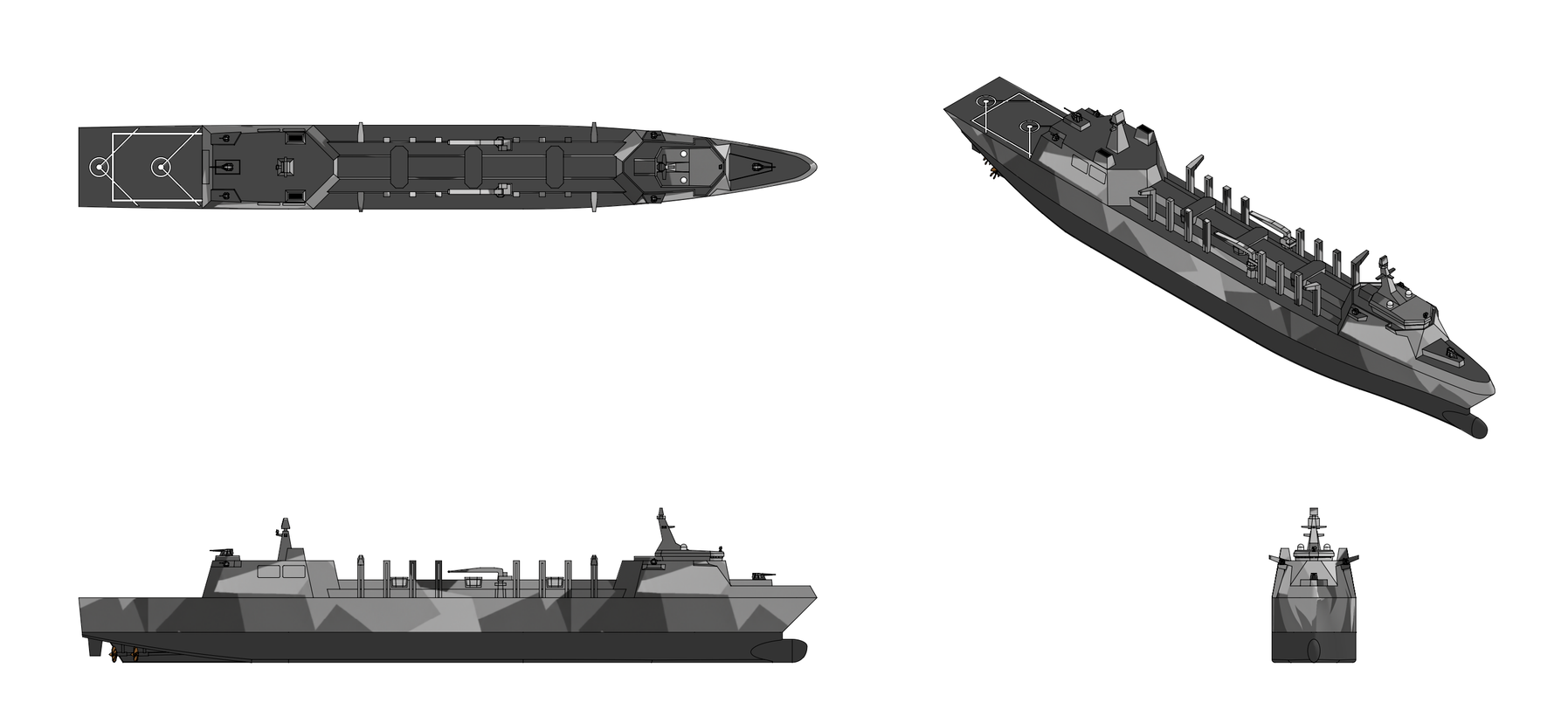
Image

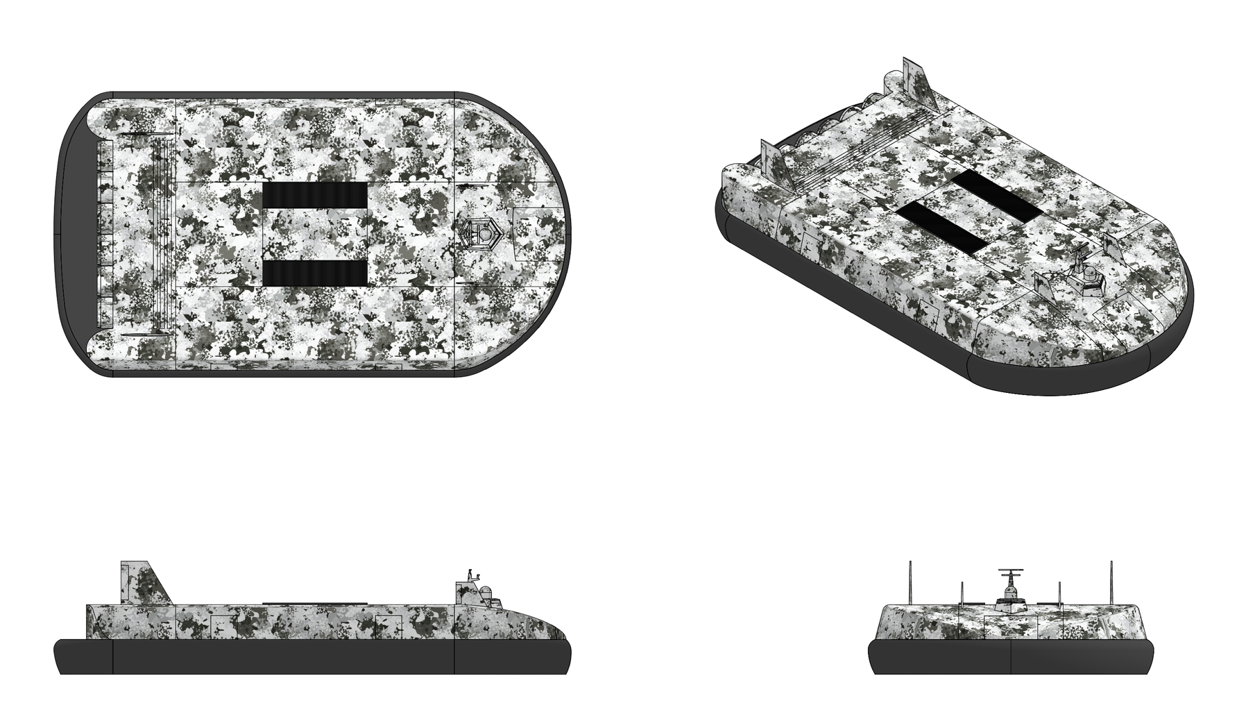
Jötunn Class

Basic Information:
  • Role: Nuclear-Powered Arctic Cargo Hovercraft
  • Mass: 5,000 t
  • Payload 3,000 t
  • Complement: 40 + 160
  • Length: 150 m
  • Beam: 80.0 m
  • Height 32.5 m
Propulsion:
  • 1x AEG 750 MWth Ultra-High Temperature Reactor
  • 4x SDI 187.5 MWth fossil fired helium heater modules
  • 6x 6.0 meter Variable geometry lift fans, 7.5 MW each
  • 6x 9.0 meter Ducted propulsors, 30 MW each

Performance:
  • Top speed (smooth ice): 145 knots
  • Top speed (water, SS4): 120 knots
  • Cruise speed: 105 knots
  • Range: Unlimited (nuclear), 1,000 km @ 105 knots (conventional mode, full payload)
  • Endurance: 90 days supplies
Sensors & Processing Systems:
  • SDI FMG 960 S band Surface Search & Navigation Radar
  • SDI FMG 970 X band Surface Search & Navigation Radar
  • SDI FMG 990 W band Ice Detection Radar


Overview:
The Jötunn class is a class of large nuclear air cushion vehicles designed by SDI Marine Systems. The Jötunn is a 5,000 tonne air cushion vehicles (ACV) that can carry up to 3,000 tonnes of cargo including heaay wheeled and tracked vehicles, containerized cargo, and various mission modules, at 100 knots over open water and at up to 140 knots over consolidated ice.


Design & Construction:
The Jötunn class vessels have a length of 150.0 meters, beam of 80.0 meters, and a height of 24.0 meters from the keep to the aft rudder fin tips. Mass fully loaded is 5,000 tonnes. The hull is a single deep box-girder construction buoyancy raft 150 m × 78 m × 4.0 m deep running the full length and width of the vehicle forming the hull, the cushion pressure boundary, the cargo deck, and the reserve buoyancy. The hull upper flange is the cargo dec and the lower flange is the flotation tank bottom plating, and its webs are the two longitudinal bulkheads separating the central hold from the port and starboard side bays. Superstructure, fan ducts, ramps, fins and machinery foundations are carried on this box. Longitudinal strength is carried by two heavy outboard side girders forming the skirt attachment backbone, four inboard girders defining the cargo bay boundaries, and a centerline keel girder that also forms the longitudinal cushion divider. Transverse frames are at 2.0 m spacing, decreasing to 1.0 m under the cargo lanes and at ramp reaction points. The reactor citadel is a self supporting titanium box structure integrated into the raft and continuous with it through the full depth of the vehicle carrying its own loads independently of the cargo deck. Watertight subdivision comprises 48 compartments, the vehicle survives flooding of any three adjacent compartments. The reactor citadel is independently watertight and gastight. Girder depth amidships is 11.0 m including 9.2 m of cargo hold clear height, 1.8 m of flotation tank depth, and the deck and bottom plating. Transverse strength is provided by watertight bulkheads at 12.5 m spacing, dividing the vehicle into 20 longitudinal zones used by the zonal electrical, hydraulic and damage control systems. The reactor trunk is an 18 m square torsion box built integrally with both longitudinal bulkheads and with the transverse bulkheads. The flotation tanks are subdivided into 48 individually vented and sounded cells providing 200% reserve buoyancy. The vehicle floats on these cells with the cushion off and retains positive buoyancy and stability with any four cells open to the sea. A hardened ice belt 3.2 m deep encircles the flotation tanks at the design waterline, constructed to a Polar Class 6 glancing impact standard, allowing the vehicle to settle amongst broken ice in routine operation. Expansion joints are fitted at the four zone boundaries to accommodate through thickness thermal gradients between the heated interior and the external ambient temperature. The hull primary structure is constructed almost entirely of Ti-5111 (Ti-5Al-1Sn-1Zr-1V-0.8Mo) titanium alloy providing high specific yield strength, complete immunity to seawater galvanic corrosion, no magnetic signature, excellent fatigue performance, and adequate weldability with proven marine fabrication procedures. Ti-5111 is used for the cargo deck and bottom plating, all longitudinal and transverse bulkheads, the flotation tank shell and ice belt, the reactor trunk, the bow and side ramp primary structures with their hinges and locks, the resting pad legs and load paths, and all helium pressure boundary penetrations. The bow, stern, and outboard side girders incorporate a 1.5 m deep crushable zone of thin wall tubular titanium crush structure elements in a syntactic foam matrix, designed to absorb a 12 MN longitudinal impulse without any penetration of the cushion pressure boundary. The reactor citadel is set a minimum of 24 m inboard of any external boundary, which is the single largest contributor to its impact protection. The bottom of the hull is a three layer system with titanium faced titanium honeycomb structural layer, a UHMWPE ablative layer in replaceable 3 m × 3 m panels, and a skid layer. Six full length longitudinal landing skids at ±6, ±18, and ±30 m from centerline, each a titanium backed AR500 steel shoe 600 mm wide and 50 mm thick on a syntactic foam crush core, run the entire length of the hull bottom. Seawater heat rejection exchangers are integrated flush into the bottom plating between the inner skid lines. Twelve hydraulically extending landing pads, four per side and four across the stern extend and hold the raft 1.2 m clear of the surface for loading, discharge, servicing, and repair, and prevent the skirt from carrying vehicle weight when parked. Retracted they lie flush within the bottom contour. Each pad carries a 400 mm syntactic foam crush core sized for 2.0 g setdown and can be set on prepared support posts at a permanent berth. With the pads extended onto support posts the skirt carries no load and the complete skirt system is accessible from beneath.

The structure above the hull including the majority of the superstructure is fabricated from carbon fiber reinforced epoxy using a toughened resin system qualified for continuous service at −60 °C. Glass fiber laminates are used where radio frequency transparency is required. Composite construction covers the superstructure and bridge, all twelve fan ducts and bellmouths, the plenum walls, the two forward and two aft vertical fins and all four rudder surfaces, the side bay weather deck panels, and all external fairings. The forward end of the superstructure contains a bow ramp and access trunk with a clear width of 20 m. In the stowed position the bow ramp closes the hull, transmits bow slam loads into the box girder, and forms the aerodynamic nose. Behind it the access trunk runs aft into the central cargo hold. Crew and passenger citadels port and starboard flank the bow trunk. Each is a three deck accommodation block with independent life support, power feeds, escape routes and provisions. The enclosed pilthouse is located above the bow ramp upper closure with sight lines over the deployed bow ramp. The forward central hold measures 26 m wide by 36 m long, being fed directly from the bow ram and connects to both side bays through openings in the longitudinal bulkheads. The reactor trunk is located in the center of the ship, being an 18 m square armored trunk extending from the flotation tank structure to the weather deck. Immediately port and starboard of the reactor trunk are the two lift fan banks each consisting of three vertical fan trunks 7 m square, in line fore and aft on 11 m centers. Each fan trunk extends the full height of the vehicle from a louvred inlet structure on the weather deck down through the cargo deck level to the cushion plenum beneath. Above the cargo dec on either side of the reactor trunk the plenum deck carries the two louvred inlet structures. Each louvred inlet structure is a rectangular housing 25 m long and 9 m wide running fore and aft above one bank of three lift fan trunks and supplying all three from a common inlet plenum. The aft central cargo compartment is located immediately aft of the reactor trunk and measures 26 m wide by 35 m long, accessed through openings in the longitudinal bulkheads which connect it to both side bays and to the two aft side ramps. The side cargo bays are each 84 m long and 22 m wide and connect to both central bays through forward and aft openings in the longitudinal bulkheads. The propulsion fan bank is located behind the cargo deck with six ducted fans in line across the stern with their ducts blended into the aft fuselage, and the two vertical fins carrying the aft rudder pair.

The vehicle's air cushion is a peripheral jet cushion that supports the entire mass of the vehicle. Air is discharged downward and inboard at 30° from the vertical around the entire perimeter of the vehicle. The momentum of this curtain confines a cushion of air beneath the hull at a gauge pressure of 4,800 N/m² acting over 10,215 m² which supports the 5,000 tonne gross weight. The peripheral seal is a bag-and-finger skirt of 9.0 m total height: a pressurized peripheral bag of 3.6 m section height and 5.4 m fingers. The bag is fabricated from a fluorosilicone coated hybrid laminate of aramid and ultra-high-molecular-weight polyethylene fibers which retains flexural modulus below −50 °C. Fingers are molded elastomer with an ice phobic surface treatment and embedded sacrificial abrasion plies. Reject heat from the power cycle is bled into the bag plenum and maintains fabric temperature above −20 °C at all ambient conditions. Each of the individual skirt segments carries a 500 bar hydraulic actuator capable of retracting the segment 1.2 m in under 0.4 seconds. Segments are retracted on command from the forward looking ice profiler immediately before the segment reaches a pressure ridge crest and are released as it passes, the predictive retraction allowing continuous high speed operation over ridged ice. The cushion is divided into eight cells by internal skirt curtains arranged as two longitudinal rows of four. Each cell is fed through independently modulated louvres from the common plenum. Differential cell pressure provides attitude control at low speed, ride control at all speeds, and limits the lift loss from a single skirt breach to 12.5%. All skirt attachment hardware is inboard of the hull's outer surface and reached from heated peripheral galleries running the full circumference of the raft at plenum level. Fingers are changed from inside the vehicle through a gasketed access hatch. Resistive heating is included on all attachment rails and bag seams held above −5 °C whenever the vehicle is on cushion or on standby. After overwater operation a purge sequence drives cushion air through bag and finger drains at high flow while hovering, expelling free water before setdown. Each finger has three drains with non-return flaps. Six additional hydraulic actuators give ±1.0 m of longitudinal and transverse skirt displacement for static trim, cargo distribution compensation, and ice accretion compensation. The bag is divided into 32 independently fed sections. Loss of up to 24 consecutive fingers is tolerated at full speed and 60 at reduced speed.


Propulsion:
The vehicle powered by a nuclear propulsion system consisting of a 750 Megawatt helium cooled ultra-high temperature reactor (UHTR) connected to a closed cycle bi-brayton power transmission system. The bi-brayron power cycle uses the reactor's helium coolant as the working fluid to drive a closed cycle gas turbine, with the resulting shaft power is used to recirculate the reactor's own coolant circuit and and circulate a set of physically separate secondary helium circuits which carry energy out to the six lift fans and six propulsion fans. The vehicle reactor is a helium cooled, graphite moderated ultra-high-temperature thermal reactor rated at 750 MWt thermal power. The core is annular with an outer diameter of 3.5 m, inner diameter of 1.5 m and active height of 3.5 m give an active volume of 27.8 m³ and a mean power density of 21 MW/m³. The annular geometry shortens the conduction path between the centerline of a fuel compact and the nearest coolant channel and limits the peak fuel temperature reached during a depressurized conduction cooldown. Fuel is in the form of tristructural isotropic coated particles. Each particle consists of a 425 µm diameter kernel of uranium oxycarbide enriched to 19.75 per cent in ²³⁵U surrounded by four coating layers. A 100 µm porous carbon buffer accommodates fission gas release and kernel swelling. A 40 µm inner pyrolytic carbon layer provides a bonding and diffusion barrier. A 35 µm silicon carbide layer forms the principal pressure boundary and the barrier to metallic fission product diffusion. A 40 µm outer pyrolytic carbon layer protects the silicon carbide during compact fabrication. Overall particle diameter is approximately 1.0 mm. Fuel particles are consolidated at a packing fraction of 35% into cylindrical compacts 12.5 mm in diameter and 25 mm long in a silicon carbide matrix. The silicon carbide matrix has a thermal conductivity approximately three times that of the graphite matrix used in earlier fuel forms, which reduces the temperature rise from compact centerline to compact surface. Compacts are loaded into axial fuel channels in hexagonal graphite blocks 360 mm across flats and 850 mm high. Each block contains 210 fuel channels and 108 coolant channels of 16 mm diameter on a triangular lattice. Four blocks stacked axially form one fuel column, and 72 columns form the annular core. The graphite blocks are nuclear grade near isotropic graphite, Blocks are keyed to their neighbors by dowels and located radially by a core barrel of silicon carbide fiber reinforced silicon carbide composite. The composite barrel retains strength at core outlet temperature, has a thermal expansion coefficient close to that of graphite, and contributes negligible parasitic neutron absorption. The core is qualified for the vehicle acceleration environment of 3.0 g vertical and 2.0 g longitudinal together with continuous cushion borne vibration in the 1 to 8 Hz band. The radial reflector is graphite and carries the twelve control drum channels. Axial reflectors 500 mm thick are fitted above and below the active core. The central column within the annulus is graphite and contains the six shutdown rod channels together with the core instrumentation thimbles. Twelve control drums are located in the radial reflector, each drum consisting of a graphite cylinder 400 mm in diameter carrying a 120° arc of boron carbide absorber on its outer face. Rotating the control rods presents the absorber toward or away from the core and provides the reactivity worth required for power operation, xenon override and temperature defect. Drums are driven by electric actuators mounted on the vessel head and operating in the cold helium space. Six shutdown rods employing boron carbide in a silicon carbide sheath are provided in the central column, held out of core by electromagnetic latches and inserted by gravity assisted by spring on loss of power or on trip signal. Either system alone has sufficient worth to bring the core to cold shutdown from any operating condition and to hold it subcritical with the most reactive element fully withdrawn. The reactor, its shield, its containment, the primary turbomachine and the four intermediate heat exchangers are assembled as a single removable module. Shielding consists of an actively cooledtungsten laminate inside the pressure vessel, Tungsten, beryllium oxide, and boron carbide plug shields with internal coolant passages, the t
thick wall steel containment vessel, ⁶Li-enriched lithium hydride external neutron shielding, and tungsten laminate and borated water jacket gamma shielding.

The primary circuit is a closed helium loop containing the heat source, the primary turbine, the primary compressor, the secondary compressor and the four intermediate heat exchangers. The primary turbine absorbs its entire output within the loop by driving the two compressors, and no shaft power leaves the primary circuit. Helium enters the core at 520 °C and 7.05 MPa at a flow rate of 250 kg/s. The helium passed through four inlet nozzles spaced at 90° where it passes downward through an annular downcomer between the vessel wall and the core barrel, which holds the vessel wall close to inlet temperature and permits construction of the vessel from modified 9Cr-1Mo ferritic steel. At the bottom of the downcomer the flow turns into the lower plenum, passes upward through the coolant channels of each fuel column, and collects in the upper plenum at 1,100 °C at 7.00 MPa. The upper plenum and the hot gas duct to the primary turbine are lined with silicon carbide composite tiles over an insulating layer of carbon fiber felt with the metal outside the insulation and cooled by inlet helium, holding all pressure boundary metal below 550 °C. The helium then passes through the primary turbine that absorbs energy to drive the two compressors. Helium expands through the primary turbine at a pressure ratio of 3.0, and develops 570 MW of power, 410 MW being absorbed by the primary compressor and 160 MW by the secondary compressor. The gas leaves the turbine at 660 °C and then passes through the four intermediate heat exchangers where exchanges 590 MW and leaves them at 205°C. The primary compressor then raises the helium to 7.05 MPa and 520 °C at where it returns to the reactor inlet plenum. The primary turbine, primary compressor and secondary compressor are mounted on a single shaft acting a single hermetically sealed machine within the reactor containment vessel. The machine has no dynamic seal to the exterior and no external lubrication supply. Rotational speed is 11,500 rpm. The turbine has four stages. Rotor and stator blading in the first two stages is carbon-carbon with CVD SiC/ZrC environmental barrier coatings with with silicon carbide reinforced composite shrouds, transitioning to SiC/SiC CMC blisks in the third and fourth stages. The primary compressor has fourteen axial stages and the secondary compressor has eleven stages, both with titanium alloy blading in the forward stages and TNM titanium aluminide alloy ( Ti–43.5Al–4Nb–1Mo–0.1B) n the rear stages where discharge temperature reaches 520 °C. The rotor is supported on gas foil bearings using the helium working fluid as the lubricating medium with catcher bearings for rundown. Power level is set by inventory control. Helium is bled to or admitted from storage tanks to change loop density and therefore mass flow at constant temperature and constant rotational speed. A purification plant treating a 1% bypass flow removes water, carbon oxides, hydrogen, methane and nitrogen through oxidizer, molecular sieve and cryogenic charcoal beds, holding total impurities below 10 ppmv. Impurity control at this level limits oxidation of the graphite core structures and carburization of heat exchanger surfaces. Total helium inventory is 4.5 tonnes across both circuits, with a 15 tonne reserve in a high pressure storage tank and an onboard recovery and purification plant.

Four intermediate heat exchangers (IHX) transfer heat from the primary circuit to the two secondary circuits. The units are arranged as two pairs, each pair serving one secondary circuit with all four are mounted within the containment vessel as part of the removable reactor module. Each IHX is printed circuit with flow passages are chemically etched into flat plates which are then diffusion bonded into a solid block. This construction provides a heat transfer surface density of approximately 1,200 m² per cubic meter and accommodates the 4.7 MPa differential pressure between primary and secondary sides within a core volume of 4.6 m³ per unit. The IHX are constructed from iAlloy 617 nickel-chromium-cobalt-molybdenum alloy selected for creep strength and for resistance to carburization in impure helium at 660 °C. Primary helium enters at 660 °C and leaves at 205 °C, secondary helium enters at 180 °C and leaves at 640 °C. The two independent secondary circuits are each supplied by two intermediate heat exchangers and serves three lift fans, three propulsion fans and two turbogenerators. Each circuit carries 125 kg/s of helium flow. The two circuits are cross connected at two points through normally closed isolation valves. With one circuit isolated the remaining circuit supplies its own six fans and two turbogenerators at full rating or supplies a selected subset of the isolated circuit's machines at reduced rating through the cross connects. The vehicle remains fully controllable on one secondary circuit at approximately half power, with lift and propulsion both retained on the same side and cushion cell modulation compensating for the resulting lift asymmetry. Secondary helium is compressed from 3.40 MPa to 7.00 MPa with a temperature rise from 55 °C to 180 °C. It gains 590 MW in the intermediate heat exchangers and leaves at 640 °C. Expansion through the power turbines to 3.55 MPa yields 245 MW at the twelve fan drive turbines and 25 MW at the four turbogenerator drive turbines, with the gas leaving at 450 °C. The precoolers return it to 55 °C, rejecting 510 MWt to the fan discharge streams. Helium is distributed from the containment penetrations to the machinery spaces through concentric piping. The hot supply line runs inside the cold return line, separated by a thin liner of Alloy 800H which traps a stagnant helium layer as insulation. The outer pipe is Ti-5111 and runs close to return gas temperature which permits conventional supports and removes hot external surfaces from the machinery spaces. Total secondary run is 520 m. Expansion is accommodated by bellows units at 40 m interval each restrained against pressure thrust by external tie bars.

Six lift fans are installed in two groups of three, one group on each side of the reactor trunk in line. Each fan is 6.0 m in diameter and delivers 1,200 m³/s at a total pressure rise of 5,750 Pa, absorbing 7.5 MW of shaft power. Air is admitted through two large louvred inlets on the weather deck, one on each side of the vehicle, each 25 m long and 7.5 m wide. Each inlet discharges into a longitudinal inlet plenum from which the three fans on that side draw. The common plenum equalizes inlet conditions across the three fans, permits any one fan to be shut down without disturbing the others, and provides a settling volume that reduces distortion at the fan face. The louvres are variable position airfoil sections of composite construction with electrically heated leading edges and reject heat trace heating in the pivots that modulate inlet area with fan demand, close completely for weather protection when the vehicle is settled, and close on the affected side in the event of fire or heavy spray ingestion. The fan rotor has 24 blades constructed from carbon fibre composite with titanium leading edge sheaths and titanium root fitting, mounted on a titanium alloy hub. The fan casing is filament wound carbon fiber with an integral titanium containment ring at the rotor plane. Downstream of the rotor a 32 vane composite stator recovers swirl and delivers axial flow to the discharge scroll. Fan discharge is collected in a scroll and delivered to the main plenum which runs the full perimeter of the vehicle within the hull box and supplies the bag and the cell curtains. The secondary circuit precoolers for that fan are installed in the discharge scroll, so cushion air is delivered approximately 10 K above ambient, raising skirt fabric temperature and reducing spray freezing on the inner skirt faces. Each fan is driven by a five stage helium power turbine through a reduction gearbox. The turbine operates at 9,000 rpm and the fan at 660 rpm. Fan speed follows from a tip speed limit of 180 m/s to control blade stress and noise. The gearbox is a two stage epicyclic unit rated at 10.0 MW with case carburized steel gearing and an aluminum alloy casing. It is pressure lubricated from a self-contained system with a heated reservoir and full flow filtration, independent of every other lubrication system in the vehicle. The power turbine has five stages with single crystal nickel base blading in the first two stages and conventional cast nickel base blading in the remaining three. The rotor runs in gas foil bearings on the working fluid. Casings are Alloy 617 with external insulation. Each turbine has an inlet isolation valve pair and a trim valve permitting individual shutdown and individual power setting.

Six propulsion fans are installed in line across the stern on a common transverse axis located 15.0 m above the keel. Each fan is 9.0 m in diameter and each duct is blended into the aft fuselage so that the aft hull surfaces that form the outer walls of the ducts form a single continuous faired structure across the stern, reducing the wetted area and interference drag associated with separate nacelles, shortening the load path between the fan thrust bearing and the hull box girder, and allowing the innerduct structure to carry the aft vertical fin loads. Air enters through a full width intake above the flight deck faired into the upper hull line with a boundary layer diverter and splitters forward of the fan faces. The intake lip and the splitters carry thermal anti-icing supplied from the reject heat loop. Each fan absorbs 30.0 MW of power and produces 350 kN of thrust at the 105 knot open water cruise condition, giving a total installed thrust of 2,100 kN. The rotor has 18 blades of carbon fibre composite with titanium leading edge sheaths mounted on a titanium alloy disc with titanium dovetail root fixings. The duct is filament-wound carbon fiber with a titanium containment ring at the rotor plane and a titanium bladeoff shield on the outboard face of each outer duct. A 40 vane composite stator downstream of the rotor recovers swirl and transmits rotor torque reaction into the duct structure. Fan diameter of 9.0 m provides low disc loading, which yields high propulsive efficiency. Each fan is driven by a six stage helium power turbine through a reduction gearbox. The turbine operates at 7,500 rpm and the fan at 450 rpm. Fan speed follows a tip speed limit of 230 m/s. The gearbox is a three stage epicyclic unit rated at 35 MW with case-carburized steel gearing, a nitride steel ring gear and an aluminum alloy casing. Lubrication is by a self-contained pressure system with a heated reservoir, full flow filtration and a chip detector. Turbine construction uses single crystal nickel-base blading in the first three stages. Each turbine has an inlet isolation valve pair and a trim valve. Any propulsion can may be shut down and its rotor allowed to windmill, or braked and locked, with the remaining five continuing at rated power.

Four turbogenerators are installed on the plenum deck, two supplied by each secondary circuit. Each unit comprises a four stage helium turbine driving a high speed permanent magnet generator directly on a common shaft. Each unit is rated at 7.5 MWe, giving 30 MWe of main generation. The turbine takes secondary helium at 640°C and 6.80 MPa and exhausts at 450 °C into the common precooler return in parallel with the fan drive turbines. Helium consumption is 6.5 kg/s per unit. Shaft speed is 25,000 rpm. The generator is a four pole machine with samarium-cobalt magnets retained by a carbon fiber containment sleeve. The stator is cooled by a closed glycol jacket connected to the reject heat loop. Output is rectified at the machine terminals and delivered to the 12 kV MVDC main ring through an integrated converter. Because the turbogenerators are supplied from the secondary circuits, electrical generation is identical in nuclear operation, conventional operation and combined operation. Backup power is provided by twin 3.0 MWe and twin 500 kWe diesel generators. Electrical distribution is via a a zonal Medium Voltage Direct Current (MVDC) electrical distribution system. The distribution voltage is 12kV DC on the main ring bus with local zone conversion to 1 kV DC for major loads, 800 V DC for medium loads, and 400 V AC (three-phase, 60 Hz) synthesized locally for legacy AC loads. Each of the twenty zones contains zonal converters, load centers, and cross connects to both sides of the main ring. Any one zone may be isolated with the remaining three carrying the full hotel and control load. The vessel includes four LFP Battery Energy Storage System (BESS) modules of 3 MWh usable energy storage each contained in fire rated pressure relieved enclosures vented overboard, liquid heated and cooled to hold cells between +5 °C and +35 °C. Charging is inhibited below 0 °C cell temperature. Battey functions include no-break power transfer, black start of the backup plant and the reactor, peak shaving, silent watch, and 90 minutes of essential loads including reactor instrumentation after total generation loss. The modules also absorb the load fluctuations of ridge crossing and heavy maneuvers.

Four fossil fired heater modules provide an alternative source of heat for the primary circuit. Each module is rated at 187.5 MWt and heats helium from 520 °C to 1,100 °C so that four modules operating together match reactor thermal power and reactor outlet temperature. The full performance envelope of the vehicle is therefore available with the reactor shut down or with the reactor module removed. The heater modules are installed on the plenum deck, two on each side, outboard of the reactor trunk. Each draws combustion air through a heated inertial separator intake on the weather deck and discharges through an uptake in the same location. In conventional operation, helium leaving the primary compressor is diverted through a bypass branch which carries it around the reactor through the four heater modules and back into the primary circuit immediately downstream of the reactor outlet and upstream of the primary turbine. Lift, propulsion, electrical generation, thermal services and ride control are identical in the two modes. Each module is a recuperated gas turbine core designed to produce a large mass flow of hot combustion gas which is used to heat the helium circuit through a helium heat exchanger. The turbine within the module drives the compressor and the recirculating gas fan and delivers no shaft power outside the module. Ambient air is drawn through the intake and compressed to 4.0 atm and 190 °C. It is then preheated to 250 °C in the air preheater against turbine exhaust. In the combustor the preheated air burns with arctic diesel or JP and is diluted by recirculated combustion gas returning at 560 °C, producing 225 kg/s of gas at 1,300 °C. This gas passes through the helium heater, transferring 187.5 MW to the helium stream and leaving at 560 °C. Of the cooled gas, 125 kg/s is returned to the combustor by the recirculating gas fan and 100 kg/s passes to the turbine where it expands to 500 °C, gives up further heat in the air preheater, and leaves through the uptake at 280 °C. The helium heater is a counterflow tube bank in with the two hottest tube rows constructed from silicon carbide fiber reinforced silicon carbide composite and the remaining rows Alloy 617. The composite tubes carry 7.0 MPa internal helium at metal temperatures approaching 1,200 °C. The air preheater is a plate-fin unit constructed from Alloy 800H. Combustor liners are silicon carbide composite with an yttria-stabilized zirconia thermal barrier coating. The compressor is titanium alloy in the forward stages and nickel-base alloy in the rear stages, the turbine and the recirculating gas fan are cast nickel-base alloy, both operating below 600 °C. Ducting and casings are Alloy 800H with external insulation. Each module carries a 2 MW permanent magnet machine mounted integrally on the compressor and turbine shaft, supplied from the 12kV DC zonal bus through a bidirectional converter. It motors the shaft to light-off speed and through to self-sustaining operation, achieving cold start to rated output in 90 seconds at −45 °C ambient. No air start supply, starting engine or hydraulic starter is fitted. In steady operation the same machine trims shaft speed against varying recirculation rate and helium side load, which decouples heater output from shaft speed and gives rapid and stable response to propulsion demand. At part load it recovers surplus turbine work to the bus. This system allows the vehicle to be started into full propulsion from stored energy alone. The energy storage modules motor one heater to self-sustaining operation, that heater raises the primary circuit to temperature, the primary circuit brings up both secondary circuits and the four turbogenerators, and the remaining three heaters are started from the resulting bus supply. The bypass circuit is a parallel branch of the primary circuit located outside the containment vessel. The circuit takes helium from the primary compressor discharge header, carries it through the four heater modules in parallel, and returns it to the primary turbine inlet header downstream of the reactor outlet. Isolation is by two high temperature helium shutoff valves in the reactor branch and two in the bypass branch. All fail to the safe (open) position which is reactor branch open and bypass closed. Valve bodies are Alloy 617 with silicon carbide composite internals and gas-purged bellows stem seals. During nuclear operation 2% helium bleed circulates continuously through the bypass and the four heater modules, holding the heat exchangers above 200 °C. This keeps the branch purged and leak monitored, prevents cold soak of the helium heaters, and removes thermal shock from the transfer sequence. Mode transfer is performed by walking the two valve positions against each other over approximately 90 seconds while the plant control system holds primary turbine inlet temperature on schedule. Propulsion is continuous through the transfer and fan speeds are unchanged.


Vehicle Management & Control:
The vehicle's active closed loop ride control system is a closed-loop controller which regulates cushion cell pressures, lift fan power and skirt segment position to hold the vehicle attitude, clearance and vertical acceleration within limits over a surface which is neither flat nor rigid. Twelve servo accelerometers are mounted at the corners, quarter points and center of the hull box, measuring vertical acceleration. Three inertial measurement units supply pitch, roll, heading and their rates. Sixteen laser clearance sensors are mounted around the periphery inside the skirt line. Pressure transducers measure cushion pressure in each of the eight cells and plenum pressure at each of the six fan discharges. Load cells at the four resting pad attachments measure skirt reaction when settled. Surface elevation ahead is supplied by the radar at 2 Hz. The eight cushion cell feed louvres modulate cell pressure with a bandwidth of 5 Hz and an authority of ±35% of nominal cell pressure. The six lift fan turbine trim valves modulate total cushion airflow with a bandwidth of 2 Hz and an authority of ±20%. The 96 skirt segment actuators retract individual segments 1.2 m in 0.4 s. The six propulsion fan deflector pairs contribute pitching moment through thrust line offset. The controller runs at 200 Hz on triplex processors in the flight control cabinet, with a model predictive outer loop at 20 Hz. The outer loop takes the surface elevation model from the radar, projects the vehicle path 90 seconds ahead at commanded speed, and computes the cell pressure schedule and skirt retraction sequence required to clear the profiled terrain while holding the acceleration objective. The inner loop takes accelerometer, clearance and cell pressure feedback and regulates the louvre positions against the schedule. The controller operates in feedforward on the terrain ahead and in feedback on the response achieved which permits it to command a cell pressure change before the vehicle reaches a ridge instead of reacting to the resulting heave. The controller holds vertical acceleration below 0.15 g RMS at the crew stations in the design ice regime, maintains daylight clearance above 0.15 m at all points on the periphery, limits pitch to ±2.5° and roll to ±3.0°, and prevents hard skirt contact at speeds above 60 knots. Four modes are selectable. Transit mode optimizes for ride quality at constant commanded speed. Ridge mode raises the clearance objective and accepts higher acceleration for crossing heavily ridged fields. Hover mode holds attitude and height with zero forward speed for ramp operations. Settling mode manages the controlled descent onto water, ice or pads following a plant trip, using the bus level energy storage and holding attitude within 1° throughout.

The vehicle's control surfaces include twin pairs of rudders located forward and aft and by air deflectors in the propulsion fan slipstreams. The forward rudder pair is mounted on the upper hull on short vertical pylons which place the surfaces clear of the hull boundary layer. Each forward surface has an area of 42 m². The aft rudder pair is carried on the two vertical fins mounted outboard of the outer propulsion ducts, each surface having an area of 68 m². All four surfaces are composite with carbon fiber skins over a foam filled substructure, titanium hinge fittings, and leading edge abrasion strip with reject heat anti icing. Actuation of each rudder is by dual hydraulic actuators and an electro-hydraulic actuator. Deflecting both the fore and aft rudder pairs in opposition produces a yawing moment with small net sideforce which turns the vehicle while deflecting them together produces a sideforce with small yawing moment which translates the vehicle laterally and is the primary means of correcting drift in a crosswind. The flight control system blends the two modes according to speed and maneuver demands. Both rudder pairs become effective above 30 knots. Air deflectors are also fitted in the slipstream of each of the six propulsion fans. Each deflector consists of a pair of composite vanes which insert progressively into the duct exit flow, deflecting the jet in yaw by up to 30° or at full insertion of both vanes reversing a portion of the flow forward. Deflectors are individually controlled with differential insertion across the six ducts producing yaw at any forward speed (including zero) and symmetric insertion produces braking. The deflectors provide directional control below 30 knots and during all hover, docking and ramp alignment maneuvers. Roll and pitch trim at all speeds is by differential cushion cell pressure. Crosswind handling is by a combination of rudder sideforce, deflector sideforce, and cushion cell trim.


Cockpit:
The Vehicle Pilothouse accommodates a pilot, copilot and two observer positions. The cockpit includes two night-vision-goggle compatible 40 x 30 degree FOV 1,280 x 1,024 pixel super XGA resolution heads up displays for both the pilot and co-pilot and eight 15 by 20 cm centimeter active matrix liquid crystal displays including two primary flight displays, two navigation displays, an engine display, a system display, and two multifunction displays which can be used to display information from the vehicle's other avionics systems. Each pilot station also includes a 20 x 13 centimeter 1024 x 768 pixel XGA touchscreen electronic flight bags (EFB). An SDI Digital Map Module (DMM) with 512 GB of removable memory is included in the cockpit which features dual channel digital map capability and supports DTED (Digital Terrain Elevation Data) level 2 (~30 m resolution) and controlled image base 10 meter (CIB-10) resolution satellite imagery maps which support color moving map display capability on the cockpit's multifunction AMLCD displays.

The pilothouse is equipped with an SDI combined vision system which fuses a synthetic vision system with the vehicle's own forward looking sensors and presents the result on head up and head down displays at both pilot stations. The synthetic vision system renders the surface ahead from the stored terrain and bathymetry database, the current ice chart, the drift model and the navigation solution, producing a continuous perspective view aligned to the vehicle's computed position and attitude. The enhanced vision element fuses data from the 95 GHz radar and from long wave infrared image the low light television imager and fuses them into one conformal scene. Database terrain provides the far field and the general form of the coastline with live sensor returns overwrite wherever available. Sea ice, which is absent from any database and changes hourly, is rendered entirely from live data. Four presentation layers are overlaid on the fused scene. The route corridor is drawn as a pair of ground referenced lines along the commanded track. The planned path from the ride control outer loop is drawn as a ribbon showing the 90 second projection, colored by the commanded clearance margin. Obstacles exceeding 4 m in profiled height are outlined and annotated with height and range. Leads, open water and thin ice identified by radar backscatter and infrared signature are shaded. The system runs a continuous integrity monitor which compares the database rendering against live sensor returns. Any persistent discrepancy in position or elevation raises a caution, suppresses the database layer in the affected sector, and flags the navigation solution for reversion to terrain referenced update.


Vehicle Decks & Cargo Handling:
The vehicle's cargo hold includes forward and aft central hold and port and port and starboard cargo holds located around the ship's central reactor and lift fan compartment that provide a combined 9,500 m² of cargo deck space. The forward central compartment connects to the bow ramp directly and to both side bays through large openings in the longitudinal bulkheads. The aft central compartment connects to both side bays through large openings in the longitudinal bulkheads aft. The amidships machinery block separates the two central compartments over its full width and height, so all movement between the forward and aft central bays passes through the side bays. The cargo hold is divided into two levels including the lower main deck, located on the upper flange of the hull box girder, and upper deck located 5.6 meters above it. The main deck has a clear height of 5.6 m which accommodates two ISO containers stacked with 0.42 m of clearance and carries all heavy vehicle traffic. Main deck strength is rated at 12.5 t/m² uniform with 75 t axle capacity. The upper deck has a clear height of 3.0 m which accommodates a single ISO container and is intended for light wheeled and tracked vehicles and containerized cargo. Upper deck strength is 5.0 t/m² uniform with 25 t axle capacity. Six internal ramps connect the main deck to the upper deck, one installed in each central compartment and two in each side bay. Each ramp has a clear width of 6 m, a gradient of 7.5°, and a rated axle load of 25 tonnes. Ramp decking is composite over titanium primary structure with a non slip surfaces. Container capacity is two tiers on the main deck and one tier on the intermediate deck with a total total capacity of 1,000 TEU. The entire cargo hold is conditioned to +5 °C from the reactor reject heat loop with dehumidification on the return side. Lashing is on a flush 0.5 m grid of Ti-5111 sockets rated at 25 tonnes per point on the main deck and 10 tonnes per point on the upper deck.

The bow ramp is the main cargo access point and has a width of 20 m and a deployed length of 40 m (two sections of 24 m and 16 m) and can be deployed on up to a 12° slope. Rated axle load is 75 t tracked and 50 t wheeled. The outer section carries a self-levelling articulated toe which conforms to broken ice, beach gravel and tundra with traction matting stowed in the ramp structure for soft ground. The ramp face is deiced from the reject heat loop and a snow-melting circuit in the toe clears a working area before vehicle movement begins. The ramp is normally deployed with the vehicle resting on its pads but can also be deployed with the vehicle on cushion and the toe grounded, where the vehicle holds station on deflector sideforce and cushion cell trim while vehicles drive off, and lifts clear without settling. This technique is standard on thin ice and on tidal beaches. In the stowed position the ramp is primary structure and its locks are dimensioned by bow slam loads. Four side ramps are also fitted, two per side, serving the forward and after ends of each side bay/ Each has a clear width of 15 m, a deployed length of 25 m, and the same 75 t tracked and 60 t wheeled axle rating as the bow ramp. Deployment time is 120 seconds. The side ramps discharge directly onto unprepared ground. Each ramp stows flush within the flotation tank structure and forms part of the hull closure when retracted. Ramp decking is composite over a Ti-5111 primary structure with the same reject heat de-icing circuit as the bow ramp. In addition to the ramps the upper side bays each featute large gull-wing side doors, located between between the forward and after rear ramps. Each door is 54 meters long and 7.2 meters deep, hinged along the weather deck edge and driven to 78° above horizontal by four 550 bar actuators and provides pier side cranes direct access to the upper cargo deck to load and unload cargo, including oversize cargo too large for the internal ramps and for modular shelter and facility units in the mobile base and for machinery modules during maintenance periods. Opened the door forms a weather shelter over the working area and deploys a fabric curtain from its outer edge which permits cargo work to continue in blowing snow. A 2.5 merer wide personnel gallery with a folding rail runs the length of the door's inner face and gives access to the container tops for lashing and unlashing. Hinge rails, seals, and the sill are heated from the reject heat loop. The seal is an inflatable perimeter section pressurized from the cushion supply, backed by sixteen mechanical wedge locks which take the sea and slam loads. With the door closed and locked the side shell is continuous and the panel carries hull girder shear through its locks and hinge line. Both doors can be opened with the vehicle settled afloat alongside a quay, settled on its pads ashore, or resting on prepared ice.

Cargo is moved within the vehicle through a combination of overhead cranes and powered roller decks. Two 150 tonne overhead travelling cranes are installed one per side bay running the full length of the bay on rails, designed to lift heavy vehicles, machinery modules and container blocks. Each has a 22 m span covering the full bay width, a lifting height of 8.5 m, and a traverse speed of 1.0 m/s. Six 50 tonne overhead cranes are also fitted, two in each side bay and two in the central hold, running on the same rail system as the heavy cranes in the side bays and on dedicated rails in the central hold. These smaller handle individual containers, palletised cargo and stores at higher speed, with a traverse of 2.5 m/s and permit container movement to continue while a heavy crane is engaged elsewhere. Powered roller decks are fitted over 4,100 m² of the main deck and 3,200 m² of the upper deck. The rollers are arranged in longitudinal lanes on 1.2 m centers with transverse transfer stations at 12 m intervals which allow movement in both directions and transfer between lanes without a crane. Each roller section is individually driven by an integral electric motor and is controlled from the cargo control station or from local panels. The system moves containers and palletized loads along and across the holds without deck tractors, positions loads beneath the cranes, and feeds the bow and side ramps directly. Rollers are recessed flush with the deck and are covered by removable plates in the lanes designated for tracked vehicle traffic. A container arriving over the bow ramp is placed on the main deck roller lane, run aft and outboard into a side bay, and either stowed in the main deck tiers by a 50 tonne crane or lifted to the upper deck roller lane for stowage there. Discharge follows the reverse sequence. Heavy vehicles bypass the handling system and drive on and off under their own power over the five ramps. Cargo operations are directed from a cargo control station on the port side of the pilothouse which carries the crane and roller control displays, the ramp position and lock indications, the stowage plan, and the weight and balance computation. Weight and balance figures are fed continuously to the flight control system. Representative loads include 40 heavy tracked vehicles of 75 tonnes, 250 wheeled support vehicles, 120 flatracks with modular shelter units, a complete forward operating base with accommodation, power, fuel, water treatment, workshops and 60 days of stores for 500 personnel, or 1,000 TEU of general containerized freight.

The cargo compartments convert to a mobile operations base by the installation of standard facility modules. Base modules are built on ISO frames and secured on the standard lashing grid as contained cargo and connect to the vehicle through four service risers in each compartment carrying 400 VAC and 750 VDC power, potable and grey water, low pressure air, hot water from the reject heat loop, and data. Installation of a complete fit takes 24 hours with the vehicle's own cranes and roller decks with no shore support required at any point. The full base fit occupies 4,000 m² of the 9,500 m² available and weighs 2,200 tonnes, which leaves 800 tonnes of payload margin and the remaining deck area for embarked vehicles, project cargo and additional working space. The medical group provides a two table surgical suite, a six bed intensive care unit, a twenty four bed ward, an isolation suite of four beds, radiography and computed tomography, a laboratory, a dental surgery, a pharmacy, and a casualty reception bay sized for twelve stretcher cases. The accommodation group adds 300 berths in four berth cabins to the 200 fitted in the citadels resulting in 500 total with sanitary modules, a gym and two recreation spaces. Modules are stowed on the upper deck of both side bays where the 3.0 m clearance suits their height and the gull wing doors allow direct loading. The vehicle and plant workshop occupies the after central compartment beneath removed upper deck panels, giving 9.2 m of overhead under the coverage of both 50 tonne central compartment cranes. The vehicle workshop accepts trackedes vehicles for major repair, and includes a hydraulic bay, a track and undercarriage bay, a tire shop, and a heated wash and steam bay. The machine, weld and fabrication shops contain CNC lathes, mills, a plasma cutting table, and press and brake capacity for structural sections up to 12 m. The command group provides a planning space, a communications center, a survey and geospatial cell, and a project management office. The laboratory group supports ice, soil, aggregate and concrete testing. Power export of 20 MWe and process heat export of up to 100 MWth are taken from the four turbogenerators and the reject heat loop through the deck connection panels, sufficient to power and heat a construction camp of 500 personnel together with a batching plant, a crushing plant and a heated aggregate store. In this configuration the vehicle supports projects of the scale of a 3,000 m runway with its aprons and hangars, a long range early warning radar site with its power plant and accommodation, a small port facility, or a mining camp.
Last edited by The Technocratic Syndicalists on Mon Aug 24, 2026 12:22 pm, edited 11 times in total.
SDI AG
Arcaenian Military Factbook
Task Force Atlas
International Freedom Coalition


OOC: Call me Techno for Short
IC: The Kingdom of Arcaenia

User avatar
The Technocratic Syndicalists
Minister
 
Posts: 2349
Founded: May 27, 2015
Inoffensive Centrist Democracy

Postby The Technocratic Syndicalists » Fri Aug 21, 2026 9:10 pm

Image


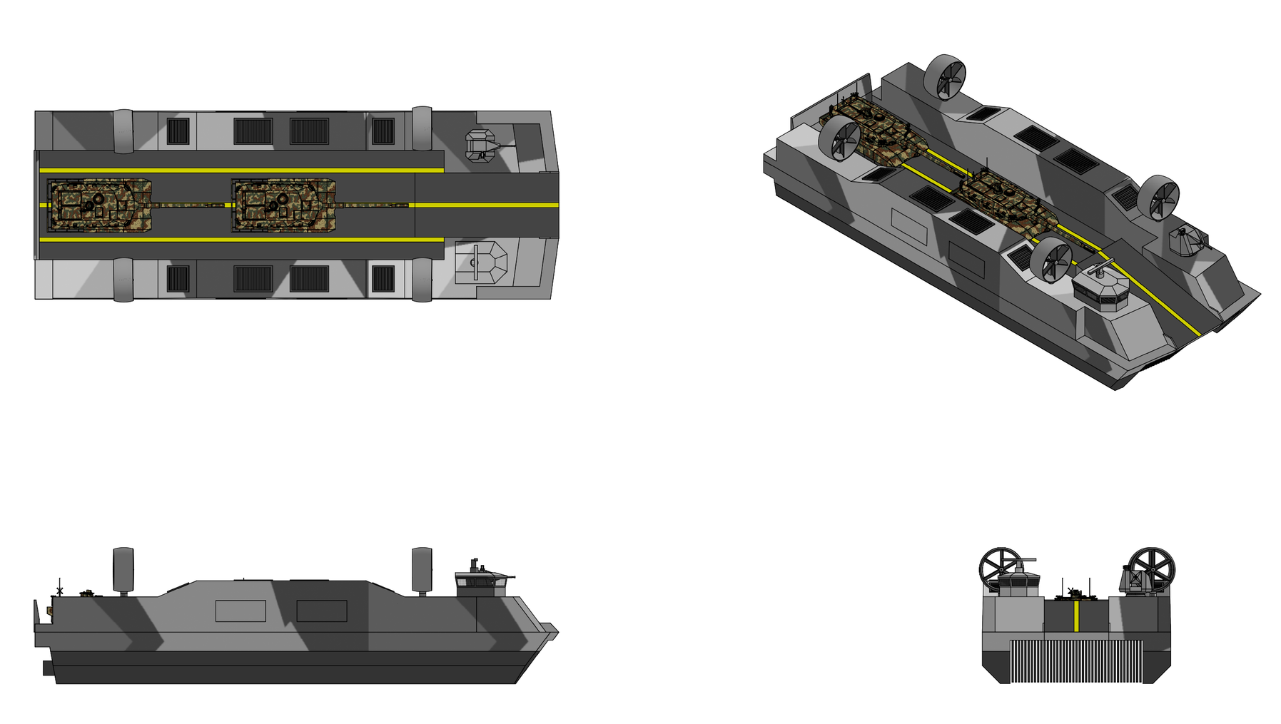
Cyclone Class

Basic Information:
  • Role: Hybrid surface effect ship/air cushion landing craft
  • Displacement: 500 tonnes full load
  • Max payload: 175 tonnes
  • Crew: 8
  • Length: 40.0 m
  • Beam: 14.5 m
  • Draft: 0.5 m (cushion), 3.0 m (off cushion)
Propulsion:
  • 2x SDI GT1500 gas turbine waterjet propulsion engines, 15 MW each
  • 4x SDI GT800 gas turbine hovercraft propulsion engines, 8 MW each
  • 2x SDI GT800 gas turbine lift engines, 8 MW each
  • 2x 1.5 MW electric motors
  • 2x SDI SS100 two-stage axial inducer waterjets, 15 MW each

Performance:
  • Top speed: 60 knots (SES mode, SS3), 50 knots (hovercraft mode)
  • Range:
      1,000 km at 50 knots (SES mode, fully loaded)
Sensors:
  • SDI Integrated Bridge and Navigation System

Armament:


Overview:
The Cyclone class is a high speed amphibious landing craft designed by SDI Marine System. The Cyclones a surface effect ship that transforms in the water into a fully amphibious air cushion vehicle, designed to transports heavy tracked and wheeled vehicles, palletized cargo, and personnel from a well deck equipped amphibious assault ship located beyond the visual horizon, transits open water at high speed in surface effect ship mode, transforms into a hovercraft on approach to the surf zone, and delivers its cargo across an unimproved beach in air cushion hovercraft vehicle mode. The vessel's high speed, shallow draft and low profile make it capable of high volume cargo transfer in contested maritime environments.


Design & Construction:
The Cyclone class has an overall length of 42.0 meters, a maximum beam of 14.5 meters, and a full load displacement of 500 tonnes with a 175 tonne payload. The hull consists of twin rigid catamaran side hulls connected by a central wet deck. Each sidehull is a watertight, longitudinally framed structure extending the full length of the ship. The interior walls of each sidehull are flat to accommodate the planing seal operating envelope. Full keel length fences are integral with the lower sidehull to reduce cushion venting and waterjet inlet air ingestion. As a conventional SES side hulls containing the central air cushion during waterborne transit, and as structural hosts for the retractable hovercraft skirt system. The side hulls are wider and deeper than a pure SES to accommodate retracted skirt storage bays. When deployed the hovercraft skirt extends outboard and beneath the side hulls, wrapping the entire hull in a continuous flexible skirt for full air-cushion hovercraft operation. The wet deck spans between the sidehulls and forms the upper boundary of the cushion volume and is a flat panel stiffened structure designed to withstand the slam pressures associated with wave impacts during on cushion operation. The cross structure spans between the sidehills and carries the cargo deck above and the wet deck below. The wet deck between the side hulls includes a complete double bottom, ensuring penetrations of the wet deck will not result in flooding of any operational space. The transverse structure bridging the sidehulls at the main deck level and above carries the global bending and torsional loads. The hull includes both hard chines and spray rails to to minimize wave spray at high speeds. The wet deck plating closes the underside of this grillage and forms the roof of the central cushion. The cargo deck plating closes the upper side and carries vehicle loads. The superstructures are erected on the twin sidehull weather decks and are framed integrally with the sidehull transverse web frames. The ducted propeller air propulsor pylon foundations are titanium space frames that distribute pylon thrust and side load into three transverse web frames and both sidehull side girders. Deployable bow and stern ramps hinge from the cross structure longitudinal girders.

The primary hull structure is fabricated from Ti-5111 (Ti-5Al-1Sn-1Zr-1V-0.8Mo) near alpha titanium alloy, offering an exceptional combination of intermediate strength, high toughness, excellent weldability, seawater stress-corrosion cracking immunity, and room temperature creep resistance. The alloy’s complete immunity to seawater stress-corrosion cracking and essentially zero corrosion rate eliminates all protective coatings, cathodic protection systems, and corrosion-related through-life maintenance — a major cost and operational benefit for a vessel spending its entire life in the marine environment. The non-magnetic hull provides inherent mine countermeasure advantages. The exceptional fire resistance (titanium does not lose structural strength until temperatures far exceeding those that would collapse steel or aluminium structures) provides superior survivability. The full cryogenic ductility of Ti-5111(maintaining toughness to liquid nitrogen temperatures) makes it inherently arctic temperature capable without the brittle fracture concerns of carbon steels. Hull construction employs conventional stiffened plate construction adapted for titanium with Ti-5111 plate cut by waterjet formed to shape, and joined by Gas Tungsten Arc Welding (GTAW) in an inert argon shielded atmosphere. Longitudinal framing is incorporated throughout. Side hull skirt storage bays are integral structural compartments with watertight doors. Propulsor fan pylons are primary structure integrated with the superstructure. Ti-5111’s cryogenic properties eliminate all low temperature material concerns. Selected hull panels employ a titanium graphite fiber metal laminate consisting of thin Ti-15V-3Cr-3Al-3Sn foils interleaved with unidirectional intermediate modulus carbon fiber plies in a high temperature thermoplastic matrix. The fiber metal laminate panels are used in the cargo deck plating and in the forward wet deck slam panels. The laminate provides a 20% mass reduction relative to monolithic Ti-5111 at equal bending stiffness, provides crack bridging in the titanium layers that reduces fatigue crack growth rates by more than one order of magnitude, and provides impact energy absorption above that of monolithic plate at equal areal mass. Carbon fiber reinforced polymer composites are used for the superstructures, cabin module, cushion air ducting, lift fan rotors and volutes, ir propulsor blades, ducts, and stators, and the air system and drive shafting. The primary structural laminate is an IM7 carbon fiber in a toughened epoxy matrix designed to resist microcracking under repeated thermal cycling to -50°C. Superstructure side and top panels are sandwich construction with carbon face sheets over a closed-cell polymethacrylimide foam core, used over a honeycomb core because it doesn't accumulate water and isn't susceptible to freeze damage. The cabin module is single piece resin infused monocoque with integral window frames, removable as units through six titanium attachment fittings. Cain windoes are high strength, heated laminated glass with embedded deicing elements and a hydrophobic coating ensures clear visibility in arctic and icing conditions.


Propulsion
SDI1500 Gas Turbine
  • Type:Aeroderivative gas-turbine
  • Length: 6,800 mm
  • Width: 2,400 mm
  • Height: 2,800 mm
  • Weight: 3,000 kg
  • Compressor: 3 stage LPC, 9 stage HPC/i]
  • Compression ratio: [i]40:1
  • Combustor: annular combustor
  • Turbine: 2 stage HPT, 2 stage LPT, 3 stage PT
  • Specific fuel consumption: 210 g/kW-hr
  • Thermal efficiency: 39%
  • Output: 15,000 kW
  • Fuel: J9, marine diesel
[/list]The ship's waterborne SES mode propulsion system consists of twin SDI500 marine gas turbine engines, one in each sidehul, driving a two-stage axial inducer waterjet thruster through a main reduction gearbox assembly. The SDI1500 is a twin-spool aeroderivative gas generator cire fitted with a free power turbine packaged in a marine enclosure with an inlet plenum, an exhaust collector, and an engine lubrication and control module. Rated performance is 15.0 MW at sea level ISA, 13.4 MW maximum continuous at 40° Celsius, and 12.1 MW maximum continuous at 50° C. Specific fuel consumption at the ISA full power rating is 0.210 kg/kWh. Power turbine output speed is 7,000 RPM. Combustion air is drawn through inlets in the sidehull weather deck fitted with a three stage separator consisting of a coalescing vane bank, a moisture eliminator, and a barrier filter, with a design salt carryover below 0.01 parts per million. Exhaust is discharged through uptakes in the sidehull weather deck fitted with the heat exchangersand with an eductor that reduces mixed exhaust temperature to 195° C. Each engine module mounts on isolators and removes vertically through a soft patch in the sidehull weather deck. Each engine bay is a Ti-5111 lined enclosure with dual loop optical flame detection, linear heat detection, and a two shot Halon fire extinguishing system with a ventilation shutdown interlock. Two main reduction gearboxes are installed, one in each sidehull immediately aft of its gas turbine. Each accepts one gas turbine input at 7,000 RPM and delivers one output at RPM to the waterjet in each sidehull. Total reduction ratio of is 9.72:1 is achieved in two stages an epicyclic first stage and a locked train double helical parallel offset second stage. The input carries a synchro self-shifting clutch which brings the gas turbine to speed and engages it automatically and which disengages the turbine when its speed falls below shaft speed. The output carries a shaft brake and a turning gear. Gears are carburized and ground from Pyrowear 675. Housings are forged Ti-5111 mounted to the deck on six vibration isolated mounts.. Each gearbox carries an independent lubrication system with dual pumps, a lubricant to seawater plate heat exchanger, chip detection with burnoff, and full flow filtration. Each gearbox output shaft is connected to an SDI Marine Systems SS100 waterjet thruster through a carbon fiber-reinforced polyetheretherketone (PEEK) drive shaft. The SDI Marine Systems SS100 is a two stage, 100 cm diameter waterjet propulsor rated at up to 15 MW of input power and consists of a low speed axial flow inducer that provides sufficient head rise to suppress cavitation at the entry to the main impeller across the full speed range and a mixed flow impeller operating at higher rotational speed provides the primary head rise and thrust generation. The impeller is manufactured from cast Ti-6Al-4V titanium alloy for maximum cavitation erosion resistance and fatigue life. The inducer is driven at a speed ratio of approximately 0.45:1 relative to the main impeller via a concentric, co-axial epicyclic gear reduction unit. Each waterjet propulsor in each sidehull is fed from a single semiflush seawater inlet with a variable geometry ramp roof. The ramp roof position is continuously modulated as a function of ship speed, pump speed, and sea state to maintain optimal inlet pressure recovery and to suppress cavitation across the full operating envelope. Inlet side plates combined with the full keel length sidehull fences prevent cushion air ingestion that could degrade propulsor performance. An active broach detection system using differential-pressure sensors at the inlet lips closes a servo loop on propulsion engine output-shaft speed to prevent overspeed events. Each waterjet propulsor discharges through a single fixed area nozzle, a flexible transom seal, and a hydraulically actuated steering sleeve. The steering sleeve at the discharge has a deflection authority of ±30° in the horizontal plane, providing turning moments without requiring rudders. The propulsors additionally incorporate hydraulically actuated thrust reverser buckets for deceleration and low speed maneuvering. Steering is accomplished through the use of thrust vectoring and differential thrust. Each waterjet drive shaft also carries a permanent magnet motor/generator mounted between the main reduction gearbox output and the waterjet input. Each is rated at 1.5 MW continuous. The machines are radial flux, interior permanent magnet, liquid cooled motors using samarium cobalt magnets. Machine mass is 1,000 kg per unit including the cooling jacket and shaft. Each is served by a bidirectional active front end converter connected to the medium voltage direct current bus. Each motor carries a clutch on its gearbox side, disengaged in displacement electric mode, which permits the machines to drive the waterjets with the gas turbines and gearboxes stopped. In surface effect ship mode the motors are backdriven by the gas turbines through the reduction gearboxes and operate as generators. In displacement electric mode the machines operate as motors supplied from the auxiliary power units and the energy storage bank, delivering a combined 3.0 MW to the two shafts with the gearbox clutches disengaged. During deceleration from high speed the machines absorb shaft energy regeneratively into the energy storage bank at up to 3.0 MW which shortens the stopping distance and recovers energy that would otherwise be dissipated in the reversing buckets. During hybrid mode and during transformation the machines provide fine control of waterjet shaft speed independent of gas turbine setting, which permits waterjet thrust to be blended smoothly against air propulsor thrust by the control system.

Four SDI800 gas turbine engines are used to drive the four air propulsion fans and eight lift fans. The SDI800 is a s a marinized derivative of SDI's TSM800 turboshaft engine. The low pressure spool comprises a six-stage axial compressor of 11.97 pressure ratio driven by a two-stage axial turbine. The high pressure spool comprises a single centrifugal compressor stage of 3.341 pressure ratio driven by a single stage axial turbine. The power turbine is a three stage axial machine on a third concentric shaft with the output connection at the front of the engine. Design speeds are 26,925 RPM for the low pressure spool, 41,350 for the high pressure spool, and 14,294 for the power turbine. Dry weight with marine accessories is 500 kg. The first stage vanes of all three turbines are variable with a throat area authority of plus or minus 16% on the high pressure and low pressure turbines and plus or minus 10% on the power turbine. The variable geometry holds shaft power approximately constant as power turbine output speed is reduced, to 80% design speed at the maximum rating and to 66% at part power settings. This characteristic is the enabling feature for the dual mode cushion system as the lift fans operate at two widely separated points on their characteristic, one for surface effect ship mode and one for air cushion vehicle mode. The constant power characteristic allows fan speed to be set anywhere in a 66 to 110 % band with the engine held at its efficient operating point and with no throttling loss. Marinization features for shipboard installation include two-stage inlet moisture and salt separator with an upstream inertial particle separator, platinum-modified aluminide and MCrAlY coatings on the single crystal turbine airfoils for Type II hot corrosion resistance, a cast Ti-6Al-4V compressor inlet housing in place of the parent aluminum casting, sealed anodize and inhibited primer on external titanium surfaces, glass isolation plies at every organic matrix composite to titanium interface, fuel system qualification on marine diesel, a 150 kilowatt permanent magnet starter generator on the accessory gearbox, a dual channel full authority digital engine control with dissimilar lanes, and an exhaust ejector with a 1.4:1 entrainment ratio that reduces mixed exhaust exit temperature to 210° C. Rated performance is 8,200 kW intermediate at sea level and 15°C s, 7,500 kw maximum continuous at 40°C and 6,800skW maximum continuous at 50°s. Four propulsion engines are installed, one in each superstructure at each end of the craft, adjacent to the propulsor each drives. Two lift engines are installed, one amidships in each superstructure. Each engine mounts to a titanium raft on three isolators with a 12 hertz vertical natural frequency. The raft carries the engine, accessory gearbox, starter generator, hydraulic pump where fitted, oil cooler, and lower drive gearbox, and removes vertically through a superstructure hatch as a single assembly. Each engine bay is a titanium lined enclosure bounded by Ti-6Al-2Sn-4Zr-2Mo firewalls, ventilated by an exhaust driven eductor, and protected by dual loop optical flame detectors, linear heat detection cable, ionization smoke detection, and a two-shot Halon extinguishing system. Engine air is drawn from inlets on the outboard face of each superstructure, positioned high above the cushion plane to minimize spray ingestion. Four ducted, azimuthing, variable pitch, fully reversible propulsors are installed at the four corners of the craft for forward propulsion in hovercraft mode, each driven by one propulsion engine. Each propeller has six blades and a 3.00 m diameter. Blades are carbon fiber reinforced polymer with a unidirectional spar, a bias ply shell, a closed cell foam trailing edge fill, and an Ti-6Al-4V leading edge erosion shield over the outer 60% of the span. Blade angle authority is -12 to plus 46° . Design speed is 1,500 RPM giving a tip speed of 230 m/s. The duct has an outside diameter of 3.20 m, a chord of 1.60 m, and a diffusing exit with an exit to disc area ratio of 1.15. The duct is a composite sandwich shell with a titanium leading edge and a titanium containment liner in the rotor plane. Duct internal surfaces carry an abradable coating permitting a 2.5 mm design tip clearance. Four stator vanes recover swirl and carry rotor thrust into the pylon, two of which are hollow and carry the shaft, pitch control lines, and lubrication lines. Each propulsor rotates in azimuth through ±35 degrees at a maximum rate of 15°/s, driven by two hydraulic rotary vane actuators supplied from the two independent hydraulic circuits, acting on a Ti-6Al-4V slew ring. Static thrust per unit at the sea level ISA intermediate rating is 90.0 kN. The drive train consists of a lower right angle spiral bevel gearbox of 1.60:1 ratio, a composite vertical high speed shaft at 7,000 RPM at design power turbine speed, and an upper combination bevel and compound planetary gearbox of 4.62:1 ratio for a total reduction of 7.39:1. Gears are carburized Pyrowear 675. Bearings are M50NiL with silicon nitride rolling elements. Housings are cast and machined Ti-6Al-4V. Each gearbox is qualified for 30 minutes of continued operation at 75 percent torque after total loss of lubricant.

The central air cushion is closed forward by a bow seal and aft by a stern seal that attach to the wet deck and to the inboard faces of the two sidehulls. The bow seal is a three lobe inflated bag with fourteen depending fingers pressurized from the lift fan discharge at 1.35 times cushion pressure. The finger array conforms to the water surface and passes the bow wave.. The stern seal is a twin lobe articulated inflated bag with a rigid backing plate hinged at the wet deck at a lobe pressure of 1.20 times cushion pressure. Backing plate position is set by two hydraulic actuators providing ±300 mm of vertical authority at a bandwidth of 3 Hz. Stern seal position is a primary trim and ride control effector in surface effect ship mode. Both seals retract by deflation and winch driven hoisting into wet deck recesses closed by hinged fairing doors. The peripheral hovercraft skirt is a loop-and-cell system of with a continuous inflated loop wrapped around the craft periphery that receives air from the lift fan discharge through eight feed trunks and distributes it to the cells. Cells are shaped as flattened truncated cones attach to the underside of the loop at their large upper base. Cells along the sides, bow, and corners are open at the small lower end. Stern cells are closed at the lower face. The skirt fabric is a woven aramid and liquid crystal polymer hybrid base cloth of 475 g/m² coated with a polyurethane and fluoroelastomer blend to a finished mass of 1,500 g/m². The coating retains flexibility to -55 ° C with a measured modulus increase below 2.5 times between 20° C and -50° C. Joints are made by a cold bonding process so that field maintenance is performed with hand tools and without heat. The outer surface carries a low ice adhesion fluoropolymer topcoat with an ice adhesion strength below 40 kPa. The peripheral skirt stows within recesses formed in the outboard face and lower outboard corner of each sidehull and within recesses in the bow and stern structure. The recesses are continuous along the full perimeter and are closed flush by hinged Ti-5111 fairing doors. Each side carries fourteen doors and each end carries five doors, latched at eight points each and driven by electromechanical actuators. Retraction is performed by 24 winch units mounted within the recesses. Each drives a tape drum that hauls a webbing tape sewn into the loop at its upper attachment line. The loop is first deflated through eight dump valves, then hauled into the recess along guide tracks, drawing the attached cells with it. The cells fold accordion fashion against the loop as it enters. Retraction time from full inflation to doors latched is under 60s. Deployment reverses the sequence, doors unlatch and open, the winches pay out under controlled tension, gravity and loop inflation pressure draw the skirt clear of the recess, and the cells fill from the loop. Recesses drain to the sidehull bilge system through eight scuppers per side fitted with non return flaps. Skirt inflation is provided by eight lift fans, four on each side. Each lift fan is a centrifugal machine with a 1.50 m rotor having twelve blades operating at a design speed of 2,600 RPM. The rotor is a composite structure with airfoil section blades co-cured to a shroud and backplate mounted on a Ti-6Al-4V hub with titanium leading edge erosion strips. The volute and inlet bellmouth are composite with a titanium wear liner at the inlet throat. Each fan carries a ring of 22 variable inlet guide vanes with an authority of +40° to -15°C degrees of pr-swirl, driven by a unison ring through two electrohydrostatic actuators, one on each electrical channel. Vane slew rate is 60°/s corresponding to a flow modulation bandwidth of approximately 2 Hz. The fan operates at two design points established by the two cushion systems presenting different system resistances. In surface effect ship mode the cushion leaks at the bow and stern seals and under the sidehull inboard keels. In air cushion vehicle mode the cushion leaks around the perimeter. In hybrid mode both cushion volumes are supplied simultaneously. The lift fan discharge on each side feeds a longitudinal plenum trunk running within the superstructure, supplying three destinations through modulating diverter valves. The first destination is the central cushion supplied through eight downcomers penetrating the cross structure and discharging beneath the wet deck. The second destination is the bow and stern seal inflation manifolds supplied through pressure regulating valves that hold lobe pressure at the specified ratios to cushion pressure. The third destination is the peripheral skirt loop supplied through eight feed trunks penetrating the sidehull structure into the skirt stowage recesses, fitted with sliding gate valves that are closed and sealed when the skirt is fully stowed. Diverter valve positions are commanded by the transformation sequencer. Valve authority is continuous which permits progressive transfer of flow from the central cushion to the peripheral skirt during the transition into hybrid mode.


The vessel electrical plant is a two level system combining SDI's zonal 12kV zonal MVDC shipboard electrical system with SDI's 270 VDC aircraft electrical system. A zonal medium voltage direct current bus carries propulsion level power at ±6 kV with a bus divided into two zones, one in each sidehull, joined by two normally open cross-tie contactors. Each zone carries the converter of one permanent magnet machine, one half of the energy storage bank, the high power thermal loads, and the converters that supply the ship service system. The ship service system operates at ±270 V direct current in two independent channels, one routed through each sidehull and superstructure, supplying the flight control computers, the electrohydrostatic and electromechanical actuators, the avionics, the lighting, the habitability loads, and the auxiliary machinery. Two auxiliary power units are installed, one in each sidehull. Each is a recuperated single shaft turbogenerator rated at 550 kW shaft output driving a permanent magnet generator and delivering 500 kWe continuous through an active rectifier. The two propulsion permanent magnet machines supply up to 3.0 MW to the medium voltage bus when backdriven by the marine gas turbines. Four 150 kW permanent magnet starter generators are mounted on the air propulsion engine accessory gearboxes and supply 600 kW when the air propulsion engines are running. These also start their engines electrically from the ship service bus which eliminates bleed air starting. The energy storage bank comprises two lithium iron phosphate assemblies of 450 kWh each, one in each sidehull, connected to the medium voltage bus through bidirectional converters with a continuous discharge rating of 2.0 MW per assembly and a peak of 3.0 MW per assembly for 60 seconds. Each assembly carries a battery management system, a resistive heater that raises the pack from -50° C to 15° C in 20 minutes, and a liquid cooling loop shared with the converters. Two additional ship service batteries provide cold ship start of one auxiliary power unit and 45 minutes of essential load. Distribution on the medium voltage bus is through solid state circuit breakers using silicon carbide devices, which interrupt fault current within 50 microseconds. A direct current arc does not extinguish at a current zero and every medium voltage feeder carries a series arc fault detection function monitoring the high frequency signature of the feeder current, opening the affected breaker within 20 ms of arc initiation. Continuous insulation resistance monitoring is applied to each bus through its grounding resistor with annunciation at 2 MΩ on the medium voltage bus and at 500 kΩ on the ship service buses. Ship service distribution is through solid state power controllers in eight load centers, four per side, providing programmable trip curves, priority table load shedding, and per circuit current and energy reporting to the platform management system. Each channel carries a 15 kW converter producing 28 V direct current and a 40 kVA inverter producing 115 and 200 V, 400 Hz alternating current for legacy equipment. The two ship service channels are physically separated with no common compartment except at the two normally open cross-tie contactors. Medium voltage and ship service cable runs are segregated by a minimum of 600 mm with intervening structure wherever routing permits. The vessel has two fully independent hydraulic circuits designated GREEN and YELLOW, operating at a 550 Bar nominal pressure. Each circuit is powered by two variable displacement, pressure compensated axial piston pumps rated at 60 L/min mounted on the accessory gearboxes of the four air propulsion engines. The two pumps of the GREEN circuit are mounted on the forward port and aft starboard engines and the two pumps of the ELLOW circuit on the forward starboard and aft port engines so that the loss of any one engine or of either sidehull forward or aft region leaves both circuits powered. Each circuit additionally carries two 40 kW electric motor driven AC motorpumps supplied from the corresponding ship service channel powering the ramps, propulsor azimuth drives, waterjet steering and reversing gear, skirt and seal handling, and fairing door actuation with the air propulsion engines shut down. Reservoirs are bootstrap type pressurized to 2.1 MPa by system pressure acting on a differential piston. The hydraulic fluid is a synthetic hydrocarbon selected for a pour point below minus 60 degrees Celsius and a viscosity of 3,300 mm²/s at minus 54 degrees Celsius, which permits unassisted cold start of the electric pumps at the arctic design temperature. Pressure and return tubing is cold worked and stress relieved Ti-3Al-2.5V. Connections are swaged fittings in straight runs and separable titanium flareless fittings at components with welded and brazed joints where the run permits. Actuator bodies are 15-5PH stainless steel with rod surfaces carrying a high velocity oxygen fuel applied tungsten carbide cobalt chrome coating. Seals are spring energized polytetrafluoroethylene with polyetheretherketone backup rings sized for the extrusion gap appropriate to 55 MPa. Filtration is to NAS 1638 Class 5 with 3 µm absolute pressure line elements and 15 µm return line elements. Fluid temperature is controlled by a fluid to air heat exchanger and a fluid to fuel exchanger in each circuit, the latter also serving as a fuel heater in arctic operation. GREEN and YELLOW each supply one chamber of the tandem actuators at the bow ramp, the stern ramp, the four air propulsor azimuth drives, and the two waterjet steering nozzles. Each circuit independently supplies the propeller pitch change mechanism of two of the four air propulsors and the reversing bucket of one of the two waterjets. Each circuit supplies the turbine variable vane actuators of three of the six air system engines. GREEN supplies the stern seal position actuators, the cargo handling equipment, and the skirt cell handling gear while YELLOW supplies the seal retraction winches, the air and marine cross connect clutches, and the waterjet inlet closure doors. Failure of either circuit leaves full ramp function at half rate, full azimuth and steering authority at half rate, pitch control on two air propulsors and bucket control on one waterjet with the remainder locked at their last commanded position, and turbine variable vane control on three engines with the remainder reverting to a fixed failsafe condition.


Passive Protection & Damage Control:
The Cyclone class features passive protection in the form of composite armor panels made from M5 ballistic fiber laminated into cured thermoplastic panels which provide ballistic impact and spall protection to the superstructure and vital areas of the ship. The ship's blast hardened bulkheads are designed to deform plastically and maintain watertight integrity in the event of an explosion from a bomb or missile warhead inside the ship and feature double-spaced plate construction with an internal fragment resistant membrane designed to stop fragments from penetrating further into the ship. The automatic opening/closing watertight doors in the bulkheads likewise feature a blast hardened membranes structure design with approximately 10 times the blast force resistance of a conventional watertight door. Damage control is assisted by an SDI Marine Systems developed Automated Ship Control System (ASCS). The ASCS is controlled by a centralized computer which amongst other functions provides real-time damage information to the crew through a graphical display located in the ship's damage control center. Additionally both the ship's pilothouse is also fitted with displays connected to the ASCS. The ACSC is designed to run automatically where after the ASCS detects damage to a compartment it will immediately isolate it and activate appropriate damage control measures. Alternatively the ASCS can be set to manual mode where the operator will have to specify the damage control measures after the system detects ship damage. The ASCS also controls and monitors the ship's engines and machinery and will alert engineers on watch duty through their assigned tablet computer when an engineering issue or machinery failure is detected and requires attention. This remove the need for time based maintenance, the system will simply alert the crew when a component or system requires maintenance. Each compartment and each piece of machinery on the ship are monitored using SDI's Two Wire Automatic Remote Sensing Evaluation System (TWARSES) which includes both visible CCD and infrared cameras located in each ship compartment. After damage is detected in a compartment the ASCS can respond in a variety of ways including isolating the damaged compartment by closing the electrically actuated watertight doors around the compartment. If the IR camera detects a fire the system will activate the compartment's overhead sprinklers and can also pump the compartment with aqueous film-forming foam , high velocity fog, and/or carbon dioxide agents if necessary. After the fire is extinguished water and firefighter agents are removed using a bilge draining pump installed in each compartment. The ASCS will also reroute ventilation, electrical power, and water around the damaged area and activate additional pumps, generators and other devices if necessary. If the compartment has been breached and is in danger of flooding the system will flood the compartment with foam which rapidly solidifies and restores reserve buoyancy. This system however is only used as an absolute last resort as it renders the compartment unusable. The ASCS also controls the ship's CBRN protection system by passing air from the ventilation intakes through containment filters before it enters the ship. Air in the ship is maintained at 5.0 millibars above local atmospheric pressure to provide a positive pressure and prevent contaminated air from entering into the ship through a breach in the hull.


Cockpit:
A single pilothouse located on the starboard deck edge integrates all craft control, navigation, cargo, engineering, and self defense functions. The pilothouse is a single-piece resin-infused carbon fiber monocoque with integral window frames, removable as a complete unit through six Ti-6Al-4V attachment points. Nine flush recessed windows are fitted, raked 30 degrees from vertical to reduce glare, sky reflection, and radar return. Glazing is a 60 mm laminated glass and polycarbonate stack with a transparent conductive interlayer for electrical heating and deicing, an external hydrophobic coating, and an internal anti-reflective coating. Straight line wipers with heated washer fluid are fitted to the forward panes. Ballistic protection is provided on the forward and port faces by Ti-5111 backing plates with an aramid spall liner, and on the glazing by the laminated stack thickness. A collective protection system provides 200 Pa of overpressure through a filtration unit with an airlock at the after entrance. Environmental control is by a 15 kW vapor cycle system with a dedicated windscreen demist duct. All interior lighting is night vision device compatible with selectable white, red, and blue-green output. Display luminance is automatically scheduled from an external photometer with a manual override. Six crew stations are included in the pilothouse. The craftmaster occupies the center forward station, the craft operator occupies the starboard forward station, the systems and engineering operator occupies the port forward station, which faces across the cargo deck. The navigator and sensor operator occupies the starboard after station. The weapon pperator occupies the port after station. The loadmaster occupies the center after station with the cargo deck display suite. Two deck engineers work in the sidehulls and on the cargo deck giving a total complement of eight. Minimum manning is four, comprising craftmaster, craft operator, systems operator, and loadmaster. Two conformal head-up displays are fitted at the forward windows, serving the craftmaster and the craft operator, presenting symbology registered to the outside world. The head-up displays are fitted with SDI combined vision system which fuses a synthetic vision system with the vehicle's own forward looking sensors and presents the result on head up and head down displays at both operator stations. The synthetic vision system renders the surface ahead from the stored terrain and bathymetry database, the current ice chart, the drift model and the navigation solution, producing a continuous perspective view aligned to the vehicle's computed position and attitude. The enhanced vision element fuses data from the navigation radar and from forward looking long wave infrared and low light television sensors and fuses them into one conformal scene. Database terrain provides the far field and the general form of the coastline with live sensor returns overwrite wherever available. Sea ice, which is absent from any database and changes hourly, is rendered entirely from live sensor data. In the standard open ocean transit mode the system presents a horizon stabilized panorama with surface contact overlays from radar, automatic identification system, and the passive aperture together with the wave profile ahead of the craft and a cushion state band. Degraded visual environment mode is entered automatically when measured extinction exceeds a threshold. Fusion weighting shifts to the radar and the sea surface is rendered synthetically so that the operator retains a continuous horizon and surface reference in fog, heavy spray, blowing snow, and blowing sand. Surf and beach approach mode renders synthetic terrain from the stored database updated in real time sensor returns. Beach gradient is rendered as a color field. The surf line and individual breaker positions are tracked and displayed with their predicted position at the craft arrival time. The projected craft footprint and skirt contact patch are drawn on the terrain along the predicted track. Obstacles down to 0.5 m are boxed at 300 m. The predicted stopping distance and turning envelope are drawn on the terrain. Well deck approach mode composites a synthetic overhead view, presenting the craft within the well deck outline with clearance to each side wall shown numerically to 0.05 m and with proximity bars for the stern gate and the well deck side walls. Cargo operations mode presents the full cargo deck, both ramps, and both ramp approaches overlaid with vehicle position, lashing status, and computed center of gravity from the cargo management system, together with ramp geometry and the predicted ramp landing point on the terrain.


Vehicle Decks & Cargo Handling:
The vessel's cargo deck is a single continuous deck running the full 30.0 meters between the bow and stern ramp sills. Clear width between the deck edge casings is 8.5 m Deck plating is TiGr laminate panels supported on the cross structure. Ti-5111 wear plates 15 mm thick are fitted in the three track paths where tracked vehicles run. The remaining deck surface carries a bonded epoxy aggregate non-skid designed for wet ice conditions with a friction coefficient above 0.4. Local reinforcement under the center heavy lane accepts the concentrated loads of a 75.0 t main battle tank at any position on the deck. Deck drainage is by 24 scuppers discharging overboard through non return flaps. Deck washdown is provided from the vessel's firemain at 16 stations. Deck lighting is by 48 lighting fixtures with selectable white, red, and infrared output, all night vision device compatible. Three vehicle lanes are marked on the deck, separated by 100 mm painted striping. The layout accepts two 3.75 m wide main battle tanks on the center lane with the port and starboard lanes held clear for personnel movement. For light vehicles, containers, and palletized cargo the deck is marked for four lanes at 3.00 m nominal width giving 120 total lane meters. The tiedown grid consists of 1,000 flush ring fittings rated at 125 kN each arranged on a 500 mm square pitch across the full deck area. Fittings are Ti-6Al-4V, recessed flush with the deck surface, and fitted with spring loaded covers designed to exclude sand and ice. Each fitting is designed for the full rated load applied at any angle between 15 and 90 degrees from the deck plane. Vehicle chocks, ISO twist locks for container securing, and 240 chain and turnbuckle assemblies at 125 kN working load are carried as craft outfit. Twist lock positions are provided at the corner points of an ISO grid across the full deck area. Bow and stern ramps provide drive through loading and discharge. The forward ramp is a three section folding assembly with a 17.50 m deployed length and 5.00 m clear width hinged at the cargo deck . Sections are joined by full width hinges with a hydraulically locked articulation that holds the deployed ramp straight under load. Ramp construction is a framework of Ti-5111 transverse and longitudinal beams with the longitudinals in line with and hinged to the craft longitudinal girders so that ramp reactions pass directly into primary structure. The running surface is TiGr laminate with Ti-5111 wear plates in the track paths and bonded non-skid elsewhere. An articulated transition flap at the outboard end conforms to the ground and removes the break angle at the ramp toe. Each ramp is driven by two tandem hydraulic cylinders per section, supplied from the twin hydraulic circuits 55 MPa, with position feedback to the cargo management system. Deployment time from stowed to fully landed is 60 s and retraction time is 55 s. Either hydraulic circuit alone deploys and retracts the ramp at half rate. Stowed the three sections fold flat and aft onto the forward ends of the cargo deck The stowed stack is latched at twelve points and carries the anchor gear, the forward mooring station, and the after mooring station on its upper surface. Ramp design crossing load is 75 t distributed over a tracked vehicle footprint. Maximum ramp articulation angle under load is 15 degrees.
Last edited by The Technocratic Syndicalists on Mon Aug 24, 2026 12:24 pm, edited 7 times in total.
SDI AG
Arcaenian Military Factbook
Task Force Atlas
International Freedom Coalition


OOC: Call me Techno for Short
IC: The Kingdom of Arcaenia

User avatar
The Technocratic Syndicalists
Minister
 
Posts: 2349
Founded: May 27, 2015
Inoffensive Centrist Democracy

Postby The Technocratic Syndicalists » Mon Sep 14, 2026 8:26 am

Image


Njord Class

Basic Information:
  • Type: Fast combat support ship
  • Displacement: 95,000 t (full load)
  • Complement: 600
  • Length: 305 m
  • Beam: 40.0 m
  • Draft: 12.8 m
Installed Power:
  • 2x SDI PWR 175 pressurized water reactor, 700 MWt
  • 4x AMG 16V 17/19 M64 diesel generators, 2,000 kWe each
Propulsion:
  • 4x SDI high temperature superconducting (HTS) AC Motors, 50 MW each
  • 4x shafts, 5 bladed fixed pitch propellers

Performance:
  • Top Speed: 33 knots
  • Range: crew endurance
Sensors and Processing Systems:
  • SDI Typhoon Combat System
  • SDI FMG 200 X band Multifunction Radar
  • SDI FMG 400 C band Air Search Radar
  • SDI Integrated Bridge and Navigation System
  • SDI EOS 400 Staring Infrared Search & Track System
  • SDI FLG 200 Radar & Electro-Optical Fire Control System

Electronic Warfare and Countermeasures:
  • SDI FMS 1800 Electronic Warfare System
  • SDI LWG 310 Naval Laser Warning System
  • SDI ZTKG 130 Trainable Decoy Launching System (TDLS)
  • SDI Sea Guardian Surface Ship Torpedo Countermeasure System

Armament:Aircraft Carried:


Overview:
The Njord class is a large nuclear powered fast combat support ship designed by SDI Marine Systems.


Design & Construction:
The Njord class ships are 305 meters long overall, 295 meters between perpendiculars, have a waterline beam of 40.0 meters, a full load draft of 12.8 meters, and a full load displacement of 95,000 tonnes. The hull is relatively blocky and full with a long parallel midbody with a fine entrance and a fine run. The transom stern is moderately immersed at full load. The freeboard and sheer forward is deliberately raised so that the forward replenishment stations remain workable in rough seas at high speed. The hull of thee ship is designed to warship survivability and shock hardening standards throughout and is divided into twenty-two watertight compartments with a triple bottom for 80% of the length of the hull. The hull is constructed from St 92 (900 MPa yield strength) high strength structural shipbuilding steel and features 100% welded construction. The hull features an advanced double hull structure consisting of inner and outer hull shells connected longitudinally by plate girders forming a continuous string of long boxes or cells. Transverse web frames and floors are minimized in order to maximize the length of uninterrupted plate panels. The cellular construction used on the hull inner bottom and double bottom, e side shell from tank top to main deck, throughout the cargo block. Conventional construction is used at the bow, the stern and bilge where plate curvature is too great for a cellular arrangement, and at the reactor compartment, main machinery room and motor room boundaries. The cellular construction saves approximately 5,000 tonnes of structural mass against an equivalent conventional warship hull with the mass savings going into passive armor protection. The stack of longitudinal cells outboard of the holding bulkhead also constitutes a multilayer side protection system, the side protection system comprising of a three layer 7.5 meter deep cellular stack with an outer void cell to provide standoff and initial fragment capture, an inner liquid loaded intermediate cell that provides blast attenuation and fragment absorption, an inner void cell providing an expansion volume and secondary flooding boundary, and an inner longitudinal holding bulkhead that acts as the inboard boundary of the system. The cellular construction also requires fewer and longer welds and produces larger uninterrupted panel which improves pre-outfitting access and reduces construction costs. Hull roll stability is enhanced by a pair of large bilge keels, one to each side, each ninety five meters in length that provide a 35% roll reduction in roll amplitude and by a pair of passive anti-roll tanks consisting of port and starboard reservoirs within the wing lanes connected by a cross duct passing above the center lane at the second deck level with an air duct and throttling valve arrangement across the tops of the reservoirs. The combined installation reduces roll amplitude at resonance by approximately 60% relative to the bare hull, extending the sea state in which connected replenishment can be conducted, reducing the roll accelerations to which the ordnance handling system is subject which permits that system to operate at rated throughput in higher sea states, and improving flight deck stability for aviation operations.

Laser welded corrugated core (LASCOR) metallic sandwich panels are used on the internal decks and platform decks within the cargo block and the machinery spaces, the secondary and joining bulkheads throughout the ship, the superstructure and deckhouse structure, the hangar structure, and the ordnance transfer deck. Each pane consists of two flat face sheets laser stake welded to a corrugated core sheet between them, the laser beam penetrating the face sheet and fusing into the crest of the corrugation to produce a continuous stake weld along each line of contact. The corrugated core provides the stiffening function that conventional construction obtains from welded stiffeners and the resulting panel requires no separate stiffening members. The panels offers high bending stiffness for a given mass in the direction of the corrugations and the design exploits this by orienting the corrugations along the principal load direction of each installation. Mass saving relative to conventional stiffened plate of equivalent stiffness is between 30% to 50% per cent depending on span and loading. Total corrugated core panel scope is approximately 8,000 tonnes of structure with approximately 3,000 tonnes of mass savings over conventional construction. The smooth face sheets further simplify outfitting, painting and cleaning and eliminate the corrosion traps that form behind conventional stiffener attachments. The core voids can be filled with damping compound with thermal insulation or left void which permits acoustic and thermal treatment to be integrated into the panel during fabrication rather than added to it during outfitting while the elimination of stiffener fitting reduces fabrication costs for the structure. Further mass savings in the superstructure are achieved through the use of Ti-5111 (Ti-5Al-1Sn-1Zr-1V-0.8Mo) near-alpha titanium alloy in the topside structure including mast and sensor platforms, the deckhouse outer skin, the replenishment kingposts and the sliding padeye support structures, weather deck bulwarks and screens, flight deck structure, hangar door structure, and the booms of the amidships cranes. Ti-5111 is also used for all seawater piping including the zonal firemains, the seawater cooling system, the ballast and antiroll tank systems, the magazine sprinkling and flooding systems, the sea chests and their strainers, and associated valves and fittings.


Propulsion:
The Njord class is powered by twin SDI PWR 175 pressurized water reactors each with a rated maximum power output of 700 megawatts of thermal energy (MWt). Each reactor is contained within its own compartment along the ships centerline, separated longitudinally be three transverse watertight compartments. Reactors are protected by the full side protection system, blast-hardened longitudinal bulkheads on each end, armored transverse boundaries at both compartment ends, and a multilayer overhead consisting of weather deck plating above an armored splinter deck. Each reactor is fueled using 97% highly enriched uranium (HEU) and is designed for a service life of over 40 years without refueling. The SDI PWR 175 reactor employs integral type circuit design with all primary circuit components including the steam generators are placed inside the reactor pressure vessel. The emergency core cooling system (ECCS) employs our separate systems including a gravity driven water injection system, pressure injection system, passive decay and heat removal system (PDHR), and a reactor protection system (RPS). The reactor core has an active length of 2.4 meters and contains 89 fuel assemblies containing binary U-Zr metallic nuclear fuel pellets consisting of 15% zirconium and 85% uranium enriched to a level of 97% U235 with a boron burnable poison coating which gives the reactor a design service life of 45 years before requiring refueling. Pumping for each reactor is provided by four horizontally mounted axial flow pumps attached to the outer shell of the reactor vessel which each provide a flow rate of 95,000 liters per minute (LPM) of cooling water through the reactor core. Each pump is powered by a 500 kW, 460 VAC 3 phase brushless AC motor driven by a variable a frequency drive (VFD). Steam from the two reactors is used to drive four turbogenerators each consisting of a cross-compound steam turbine with high pressure and low pressure turbines, a moisture separator and reheater between the stages, and a 120 Hz, 6 phase, 4160 VAC, 87.5 MW superconducting synchronous generator driven at 3,600 rpm. The four turbogenerators sets are placed in four separate non adjacent compartments, each supplied from a main steam header cross connected at both reactor compartments through armored penetrations with isolation valving at the compartment boundaries so that either reactor plant is capable of supplying all four turbogenerators sets.

The 350 MWe of electrical power from the four turbogenerators is distributed throughout the ship using a DC zonal electrical distribution (ZEDS). The 4160 VAC from the four turbogenerators is converted to to ±6000 VDC with four power conversion modules (PCMs) attached to each generator. The PCMs then supply both port and starboard DC buses which supply power to 24 electrical zones which each include one DC/DC PCM per bus (two each per zone) which converts the 6000 VDC to 750-800 VDC or 650 VDC to supply DC loads in each zone. Both DC/DC PCMs in each zone also supply one or more DC/AC PCMs with 750-800 VDC which then converts the 750-800 VDC to 450 VAC at 60 Hz for AC loads. All electrical loads in each zone are connected to both port and starboard bus ensuring continued operation if either port or starboard bus becomes inoperable. The two longitudinal buses run the full length of the ship in armored cableways. The port bus runs at the second deck level and the starboard bus at the fourth deck level which gives a vertical separation of approximately eight meters in addition to the transverse separation of approximately twenty-seven meters. Each bus is divided into 24 segments at the longitudinal bus distribution nodes, one node per zone station, and each node incorporates segmentation capability to isolate damaged segments. Energy storage modules are fitted in each zone which supply the zonal load during the interval between loss of a generation source and restoration of capacity. Each zonal module has a power rating sufficient to supply the u-interruptible and short term interrupt loads of its zone and an energy rating sufficient to supply them for ten minutes which allows for successive faults during the period required to bring an additional generator set online.

The ship's integral electric propulsion system includes four SDI designed 50 MW superconducting motors which directly drive the ship's two propellers. Each 50 MW superconducting motor is a three phase, six pole synchronous air-core AC motor with a brushless exciter which has a rated speed of 150 RPM at its design voltage of 7,200 VAC with a full-load efficiency of 97.5%. The complete motor with cryocooler assembly weighs 75 tonnes, approximately 80% less than a conventional AC induction motor of the same RPM and power output. The rotor employs yttrium-barium copper-oxide (YBCO) high temperature superconducting ceramic conductors and is cryogenically cooled to 77° K using gaseous helium from twin cryocooler modules containing single Stage GM cryocoolers located at the non-drive shaft end of the motor which feeds helium gas into the rotor through a rotating seal at the back end of the motor. The rotor housing is further enclosed in a vacuum sealed cryostat to maintain cryogenic temperatures inside the rotor. The stator coils of the motor are made from copper litz conductor and are cooled using a liquid dielectric coolant circulated through a heat exchanger to the chilled water system. Each motor employs a variable-frequency drive (VFD) with three separate 2,400 VAC three-phase power modules per drive which allows for efficient motor operation from 6 up to 150 rpm. Each 50 MW motor is used to directly drive a single 7.5 meter diameter 5-bladed fixed pitch propeller (CPP) located at the end of a carbon fiber reinforced plastic (CRFP) alloy propeller shaft. Steering is provided by a set of four flap rudders of approximately 35 m² area each with a 45° main blade angle and a 45° flap angle to deliver a total 90° deflection for superior vessel maneuverability, each actuated by a rotary vane actuator with dual independent power units per rudder. The four rudder layout is designed to enhance course keeping and during replenishment at sea operations, enabling the ship to hold course within tight tolerance against the hydrodynamic interaction forces between two large hulls at close spacing at speeds of 5 to 15 knots with a carrier alongside, proving high control authority at small helm angles with smaller and slower rudder motions, reducing yaw excursion and rig loading. Auxiliary maneuvering capability is provided by three retractable azimuth thrusters in the bow and two retractable azimuth thrusters in the stern, each rated at 5 MW shaft power that provide dynamic station keeping capability and can automatically maintains the vessel's position and heading in all sea conditions.


Sensors & Processing Systems:
SDI Typhoon Combat System: The SDI Typhoon Combat System (TCS) is a comprehensive open-architecture anti-aircraft warfare (AAW) combat management system designed by SDI Missiles & Fire Control Systems which provides fully automated detection, identification, and engagement of air targets. The primary components of the Typhoon Combat System are the Sensor Fusion Processor (SFP), Command and Decision System (C&DS), Typhoon Display System (TDS), Weapons Control System (WCS), and Integrated Ship Computing System (ISCS). The sensor fusion processor or SFP takes tracking data from the ship's radars, IFF system, distributed IRST sensors, and electronic warfare system and correlates them using a contact-to-track data correlation algorithm to provide a single integrated track of each detected target. With the contact-to-track algorithm detected contacts from each sensor (radar, IFF, IR, and ESM) are correlated with existing sensor tracks and merged using a smoothing filter to create a single track file of each correlated target. This allows (for example) the range data from the radar tracks of the dual band radars to be fused with the angle track data from the higher angular resolution IRST sensors, creating a fused 3D track which is more accurate than either the individual radar or IRST sensor tracks. Track data from the sensor fusion processor is fed into the Typhoon Command and Decision System (C&DS) which uses both IFF data and aided and automatic target recognition (Ai/ATR) algorithms to provide identification, threat classification, and weapon assignment of target data input from the sensor fusion processor. Information from the Command and Decision System (C&DS) processor is displayed via the Typhoon Display System (TDS) which uses large multi-function color displays inside the ship's CIC to display target tracks and other situational awareness data to the ship's crew and captain. The TDS consoles also features keyboards for data input which allows doctrinal IF/THEN instructions to be input to the system to the modify its behavior; such as instructing the system that IF any target is detected above a certain speed and altitude in a certain sector THEN it is to be automatically classified as hostile and engaged with a certain missile. The Weapons Control System (WCS) is responsible for launching missiles at targets identified as hostile by the Typhoon Command and Decision System (C&DS). Targets are matched to the ship's missiles by the C&DS which will then send a fire instruction to the weapon control system when the target has entered the engagement zone of the specific missile. The WCS then sends a a firing instruction to the ship's VLS to fire the specific missile and then uses the ship's radars and datalinks to provide midcourse guidance as necessary to guide the missile towards its intended target. The WCS is also responsible for providing Air Intercept Control (AIC) functionality and can be used to guide carrier or land based airborne interceptors towards a hostile target being tracked by the ship. Finally the Integrated Ship Computing System (ISCS) acts as the central processor of the Typhoon combat system and processes radar and and other sensor data and connects all the ships systems including weapons, countermeasures, and communications system together. The ISCS architecture is based on SDI's SPPC10D single-board computer, a ruggedized, shock hardened and conduction cooled computer which employs a 10nm gallium nitride (GaN) on silicon architecture, 48 core (384 thread) superscalar symmetric multiprocessor with a 4.0 GHz clock rate as well as 64 GB of DDR5 DRAM. The SPPC10D computers are each packaged into 16 Electronic Modular Enclosures (EMEs) which each include their own power, shock, vibration, and electromagnetic protection, and water cooling systems. Each EME is a self-contained server and carries 235 cabinets containing the SPPC10D single-board computers. The EMEs which run the ISCS software are interconnected to the rest of the sensors and electrical systems through fiber-optic cables and uses voice-over IP for internal communications between computer systems. The combined computing power of the ship's processors is 27,000 MIPS (million instructions per seconds) at 4.35 GHz with a combined 240 TB of data storage.

An additional ability of the Typhoon Combat System is Distributed Engagement Capability (DEC) which allow target tracking data from multiple sensors across multiple Typhoon equipped platforms in the battle group to be fused together to create a composite track of all air objects within the battle force area and to allow for hunter-killer functionality in the battle group by allowing unit in the battle force to engage a target being tracked by another unit even when the shooter is unable to see or track the target with its own sensors due to either jamming, battle damage, or line-of-sight restrictions. Distributed engagement capability on Typhoon equipped platforms s enabled by a data distribution system (DDS) and a track fusion algorithm (TFA). The data distribution system or DDS consists of four C band planar array antenna assemblies blended into the outer surface of the ship's superstructure which provide extremely high bandwidth line-of-sight communication capability with other sea and air platforms in the battle force. Each DDS antenna array consists of a liquid cooled digital beam forming (DBF) antenna with separate transmit and receive arrays employing gallium nitride (GaN) monolithic microwave integrated circuit (MMIC) transmit/receive (T/R) modules integrated into a common subarray line replacement units (LRUs) and high provides extremely jam resistant and high bandwidth line-of-sight data exchange with other DDS equipped platforms. The track fusion algorithm (TFA) uses the ships ISCP processors to take sensor data received by other units through the data distribution system and fuse it with data from the ships own sensors to create a single composite sensor picture. The main capability of the track fusion algorithm is the ability to network the measurements of radars and other sensors on different platforms tracking the same target and combine them with an intelligent averaging algorithm that creates a single composite track of the target which is more accurate than the track of any individual sensor. When a Typhoon equipped platform establishes a target track with one or more of its sensors a track alert is broadcast across the Typhoon network which then cues the other platforms in the battle force to point their sensors in the direction of the target track. When the other platforms begin tracking the target with their own sensors their sensor measurements are distributed back across the network to every other platform to form the composite track. This capability allows the battle force to maintain track of a target even if any one or even multiple of the battle force units loses the target track due to jamming, battle damage, or environmental effects. When used to fuse radar data from different platforms the track fusion algorithm also enables better radar observation of low observable targets by illuminating them simultaneously with many radars of different wavelengths and scan rates at once, allowing a composite track to be created even if none of the radars in the battle force are able to generate an individual track of the target for more than a few pulses.

SDI EOS 400 Staring Infrared Search & Track System: The SDI EOS 400 Staring Infrared Search & Track System is a distributed multi-aperture sensor system which consists of five identical mercury cadmium telluride (HgCdTe) starring focal plane array (FPA) imaging infrared (IIR) sensor units placed around the ship's superstructure which provide combined 360°azimuth and -20° to +75° elevation situational awareness infrared search and track (SAIRST) capability against surface vessel, cruise missile, ballistic missile, and aircraft targets to supplement the active search and track capability of the ship's dual band radar system. The 4096 × 4096 pixel (16 MPA) HgCdTe sensor used by each sensor head operates in the MWIR (3–5 µm) band and features a 95 x 95 degree field of view. The image processing features of the SIRST system include automatic target recognition (ATR) using an on-board threat library, passive ranging algorithms, multi-target adaptive tracking, and clutter rejection techniques. The video feed from the sensor units can be stitched together and displayed on operator consoles in the ship's bridge and CIC to act as a navigational aid and to provide close in situational awareness for the ship's crew.

FLG 200 Radar & Electro-Optical Fire Control System: For short range surface target tracking and gunfire control the ship is equipped with two SDI FLG 200 combined radar and electro-optical fire control directors mounted forward atop the forward and aft superstructures. The FLG 200 contains both a Ku band (15.5 - 17.5 GHz) solid state radar and an electro-optical suite containing a thermal imager, television camera, and laser rangefinder which is intended to track both surface targets and subsonic and supersonic sea-skimming missiles in close proximity to the vessel and provides sector search capability, missile launch detection and tracking, and own ship gun fire projectile tracking and splash point detection. The Ku band monopulse radar employs a solid-state Cassegrain antenna connected to a digital receiver and signal processor and transmits with a peak power of 1.5 kW and has a maximum instrumented range of 36 kilometers. The radar is designed with a high level of ECCM features including extremely low sidelobes, high instantaneous bandwidth, and high frequency agility. The electro-optical suite consists of a 1280 x 1024 pixel Midwave IR (3–5 µm) thermal imager with 0.92° to 30.0°horizontal field-of-view and 30x continuous optical zoom, 1920 x 1080 pixel CCD daylight television camera with 64x continuous optical zoom, and an Nd:YAG OPO-shifted 1.54 μm eye-safe laser rangefinder with 50m to 40 km range and <1 meter accuracy. The electro-optical system features automatic tracking of up to four simultaneous targets, automatic sector surveillance, simultaneous TV and IR tracking and sensor fusion, recording capability, and integral GPS interferometer system (GPSIS) for far target location (FTL) capability using the system's laser rangefinder to provide 10-digit grid geo-location of surface targets accurate to within 60 meters at ranges up to 40 kilometers. both radar and electro-optical systems are enclosed in a low-RCS triaxially stabilized mounting capable of elevating from -20 to +120° at a rate of 160 °/s and training a full 360° at a rate of 140 °/s.


Electronic Warfare & Countermeasures:
FMS 1800 Electronic Warfare System The primary electromagnetic countermeasure system of the Tempest class cruiser is the FMS 1800 Electronic Warfare System, a comprehensive offensive and defensive electronic warfare (EW), electronic support measures (ESM), and electronic intelligence (ELINT) suite which combines passive radar warning receivers and phased array jammers for long range, over-the-horizon detection, identification, and targeting of threat emitters as well as automatic employment on-board RF countermeasures and support of passive over-the-horizon targeting capability for the ship's weapon systems. The passive radar warning system of the FMS 1800 consists of multiple single-quadrant, high-gain linear interferometer arrays smoothly blended into the superstructure of the vessel connected to a set of digital receivers and pulse processors inside the ship's superstructure which provide for 360° spherical broadband, all aspect detection, identification, and direction-finding of radar emissions in the 0.5 to 40 GHz range and communications in the 30 to 3,000 MHz range with the capability for <1° RMS direction finding and precise emitter location and threat identification capability against low probability of intercept waveforms and with additional over-the-horizon direction finding capability of HF, VHF, and UHF band signals. The offensive electronic warfare capability of FMS 1800 system includes multiple low, mid, and high band electronically scanned gallium nitride (GaN) based Digital Radio Frequency Memory (DRFM) jammers blended into the superstructure which provide for the jamming of hostile RF sensors in the 2 to 40 GHz range.

LWG 310 Naval Laser Warning System: For detecting laser sources including laser range finders, laser target designators, and laser beamriding missiles the ship's FMS 1800 system is augmented by an SDI LWG 310 Naval Laser Warning System. The vessel's LWG 310 installation consists of a central controller connected eight sensor heads, four on each side of the superstructure, providing combined 360° coverage around the vessel. Each individual sensor head features 110° azimuth and +/- , 70° elevation coverage and is capable of detecting up to eight simultaneous laser range finders laser target designator emissions in the 0.5 μm - 1.65 μm range and laser beamriders in the 0.8 μm - 1.1 μm range.

SDI Sea Guardian Surface Ship Torpedo Countermeasures System: The ship is fitted with the SDI Sea Guardian Surface Ship Torpedo Countermeasure System which combines various soft-kill and hard-kill torpedo countermeasure systems. The Sea Guardian system consists of a towed array sonar designed specifically for torpedo detection, a towed acoustic decoy with a a single-drum winch, an interface to the ship's trainable decoy launchers, and a processing cabinet with two display consoles, and and four 6-round anti-torpedo torpedo launchers on either side of the ship. The towed array sonar used by the system is a combined active and passive array sonar optimized to detect the high frequency sound signature of torpedo screws and active sonar homing heads. The towed array is supported by two vibration isolated modules (VIMs) located on either side of the sonar with the array being connected on one end to the ship using a fiber-optic tow cable and connected on the other end to the towed decoy with an array tow cable. The towed decoy array is designed to emit simulated ship noise such as propulsor and engine noise to lure a passive-sonar homing torpedo to the decoy instead of the ship. The towed decoy can also receive sonar pings from the active homing head of a torpedo and amplify and return the "pings" to the torpedo, presenting a larger false target to the torpedo. The hardkill component of the Sea Guardian system comprises a series of four box launchers on either side of the vessel which each contain six SDI S2s Barracuda anti-torpedo torpedoes in individual all-up rounds (AUR) which contain the Barracuda torpedo and a self-contained compressed gas launch system. The Barracuda torpedo is 21 cm in diameter, 2.0 meters in length, weighs 110 kilograms, and contains a 20 kilogram aluminized PBX explosive warhead. The guidance and fusing system of the Barracuda is designed to explode it in front of the oncoming torpedo and create a pressure wave which crushes the nose section of the oncoming torpedo. The Barracuda has a maximum firing range of 10 kilometers and is propelled by an advanced stored chemical energy propulsion system (ADSCEPS) which can propel the Barracuda at speeds up to 60 knots at depths up to 1,000 meters. Although designed as an anti-torpedo the Barracuda can also be used to engage midget submarines, naval mines, and unmanned or autonomous underwater vehicles.

ZTKG 130 Trainable Decoy Launching System (TDLS): The ZTKG 130 Trainable Decoy Launching System (TDLS) is an aimable decoy launcher which can launch a variety of decoys designed to decoy away anti-ship missile and torpedo threats. The ZTKG 130 system consists of multiple 12-round trainable countermeasures launchers controlled by a central command console inside the ship. Each 12-round launcher employs a rotating platform with 12 separate 130mm barrels which can each be individually trained in elevation. The ship is fitted with four decoy launching systems, two on either side of the ship used for acoustic torpedo decoys (24 total) and another two launcher on each side used for chaff/flare rounds and missile seduction decoys (24 total).

    AM5 dual chaff/IR seduction decoy:The primary chaff seduction round employed by the DLS is the AM5 dual chaff/IR seduction decoy which is capable of defeating dual-seeker missiles equipped with both IR/EO and radar seekers. The AM5 releases clouds of super-rapid blooming chaff with a 10,000 m2 RCS in the X band along with a series of spectral infrared flares with full coverage in the MWIR (3-5 µm) and LWIR (8-14 µm) bands. The chaff clouds and flare submunitions of the AM5 are designed to be deployed at increasing distances and altitudes from the ship, creating a "walk-off" effect which leads the missile seeker away from the ship.

    AM79 Buzzard active missile decoy: For decoying away radar-guided anti-ship missiles the DLS can deploy the AM79 Buzzard active missile decoy, an expendable electronic-warfare rotary-wing drone which is designed to seduce RF guided anti-ship missiles by simulating the radar return of a large surface vessel. The buzzard features a cylindrical shaped fuselage 130 mm in diameter and 0.9 meters tall with both top and bottom mounted 1.8 meter diameter three-bladed counter-rotating coaxial rotors powered by two brushless DC motors. The rotors unfold from the body of the decoy after launch and fly the decoy into a pre-programmed flight path away from the ship where the decoy then hovers in place while emitting electronic warfare signals uses its fuselage mounted Digital Radio Frequency Memory (DRFM) jammers which are designed to seduce oncoming anti-ship missiles into targeting the decoy and not the host vessel. The decoy is powered by a thermal battery mounted in the center of the fuselage which gives the decoy approximately 60 minutes of flight endurance after launch.

    AM7 Lamprey acoustic decoy:The DLS can also launch the AM7 Lamprey, a 130mm diameter, expendable acoustic decoy designed to counter torpedo threats. After a rocket-powered launch into ocean the Lamprey is programmed to hover vertically using a pressure-controlled motor driving a small, shrouded propeller in the tail of the decoy. The Lamprey is designed to hover at a pre-selected depth from 10-300 meters where it listens for torpedo transmissions. Active acoustic transmissions are detected and analyzed resulting in decoy selectivity and generation of the appropriate deception signal for transmission including target signature and target self noise. If no torpedo transmissions are detected the decoy is programmed to emit warship propulsor and engine noise to lure in passive homing torpedoes. Power for the motor and electronics of the Lamprey is provided by a thermal battery. The Lamprey is programmed to hover and emit noise until the battery dies where the decoy then sinks and all software onboard is erased.
[/list]


Signature Reduction:
the Njord class features extensive radar and infrared signature reduction to reduce the ship's detectability to radar and infrared sensors. The hull and superstructure feature a faceted shape with an enclosed mast and sensors suite designed to eliminate corner reflectors and reduce the ship's detectability by radar systems. The superstructure of the vessel is fitted with SDI's S-RAM, a type of ballistic grade structural radar absorbing material consisting of 2 cm thick panels made from multiple layers of M5 fibers fibers containing a lossy filler backed by a carbon fiber laminate acting as a reflector. The panels are designed to survive extreme weather exposure and ballistic damage and provides an average -20 dB reflectivity across the 2-40 GHz frequency range (L through Ka bands). The rest of the steel hull is painted in a radar absorbing paint coating 1 to 5 millimeters thick consisting of lossy dielectric material embedded in a polymer resin which provides -20 dB reflectivity across the 9 -13 GHz range (X band).

The magnetic signature of the vessel is reduced by SDI's High Temperature Superconducting Degaussing System (HTSDS) which is designed to reduce the vessel's magnetic signature. The superconducting system provides an over 95% reduction in the ship's magnetic signature with a total weight 80% less than a conventional copper cable based system that reduces the vulnerability the ship to magnetic mine threats. The degaussing system components include a control unit, power modules, junction boxes, cryo coolers, accumulation tanks, high temperature degaussing cable assemblies, and cryogenic cold gas lines used to cool the degaussing cable assemblies. The system uses three separate loops of independently controlled degaussing coils arranged in three axes which are designed to counteract the ship's magnetic signature in the vertical, longitudinal and athwartship planes. Each coil loop is connected to an independent power module connected to the ship's zonal DC power distribution system which energizes the coil with up to 3,000 Amps of current at voltages of up to 138 kV. The cable assemblies consists of a hollow bismuth strontium calcium copper oxide (BSCCO) high temperature superconducting cable wrapped around a hollow support tube and supported by a flexible cyrostat consisting of a layer of inner corrugated stainless steel tubing, a layer of multi layer insulation (MLI), a polymer support layer, a vacuum space, an outer layer of corrugated stainless steel tubing, and an outer cable sheathing. The cooling loop for each cable includes a cryogenic refrigerator, a seawater heat exchanger, and a circulation pump which pumps gaseous helium through the cryostat and hollow support tube to maintains cable temperature at 55° K. The entire HTSDS is controlled from a central degaussing control unit (DCU) which receives magnetic field data either from both a shipboard triaxial magnetic probe system and from a magnetic geophysical model which takes data from the ship's navigation system and automatically calculates the required current for each degaussing coil to cancel out the ship's magnetic signature.


Passive Protection & Damage Control:
The Tempest class cruiser features features passive protection in the form of several hundred tonnes of composite armor panels made from M5 ballistic fiber laminated into cured thermoplastic panels which provide ballistic impact and spall protection to the superstructure and vital areas of the ship. The ship's S70 VLS modules and the magazine for the 20.3 cm gun are are also encased with welded Ti-6211 titanium alloy plates 50 to 80 mm thick backed by a spall liner consisting of M5 ballistics fibers embedded into an epoxy resin matrix. Th ship's blast hardened bulkheads are designed to deform plastically and maintain watertight integrity in the event of an explosion from a bomb or missile warhead inside the ship and feature double-spaced plate construction with an internal fragment resistant membrane designed to stop fragments from penetrating further into the ship. The automatic opening/closing watertight doors in the bulkheads likewise feature a blast hardened membranes structure design with approximately 10 times the blast force resistance of a conventional watertight door.

Damage control on the Tempest is largely automated due in parts to SDI Naval Systems developed Automated Ship Control System (ASCS). The ASCS is controlled by a centralized computer which amongst other functions provides real-time damage information to the crew through a graphical display located in the ship's damage control center. Additionally both the ship's bridge and CIC also also fitted with displays connected to the ASCS. The ACSC is designed to run automatically where after the ASCS detects damage to a compartment it will immediately isolate it and activate appropriate damage control measures. Alternatively the ASCS can be set to manual mode where the operator will have to specify the damage control measures after the system detects ship damage. The ASCS also controls and monitors the ship's engines and machinery and will alert engineers on watch duty through their assigned tablet computer when an engineering issue or machinery failure is detected and requires attention. This remove the need for time based maintenance, the system will simply alert the crew when a component or system requires maintenance. Each compartment and each piece of machinery on the ship are monitored using SDI's Two Wire Automatic Remote Sensing Evaluation System (TWARSES) which includes both visible CCD and infrared cameras located in each ship compartment. After damage is detected in a compartment the ASCS can respond in a variety of ways including isolating the damaged compartment by closing the electrically actuated watertight doors around the compartment. If the IR camera detects a fire the system will activate the compartment's overhead sprinklers and can also pump the compartment with aqueous film-forming foam , high velocity fog, and/or carbon dioxide agents if necessary. After the fire is extinguished water and firefighter agents are removed using a bilge draining pump installed in each compartment. The ASCS will also reroute ventilation, electrical power, and water around the damaged area and activate additional pumps, generators and other devices if necessary. If the compartment has been breached and is in danger of flooding the system will flood the compartment with foam which rapidly solidifies and restores reserve buoyancy. This system however is only used as an absolute last resort as it renders the compartment unusable. The ASCS also controls the ship's CBRN protection system by passing air from the ventilation intakes through containment filters before it enters the ship. Air in the ship is maintained at 5.0 millibars above local atmospheric pressure to provide a positive pressure and prevent contaminated air from entering into the ship through a breach in the hull.


Replenishment Systems:
The ship carries a total of eight heavy replenishment at sea (HRAS) stations (four per side), four doubled fueling at sea (FAS) stations (two per side), two astern reel refueling stations, and four movable highpoint reception units. The arrangement allows a carrier along one side and up to two escorts along the other side to be replenished simultaneously. The eight all-electric heavy replenishment at sea (HRAS) stations, four on each side of the vessel are designed to transfer dry cargo and ordinance. Each system includes a single heavy jackstay wire held in constant tension to support the weight of the load with the load rolling over the jackstay wire running on a two sheave traveler assembly which is pulled in either direction by inhaul and outhaul wires, the traveler assembly designed to keep the profile of the projecting steel wire ropes as low as possible when it enters the reception area inside the receiving vessel's reception pocket. The installation operates at vessel speeds between 5 and 15knots and in sea states to sea state 5. Operational vessel separation is between 24 and 55 meters, and the rig can remain connected out to 100 meters. Load mass is up to 6.0 tonnes including the stores skid, and maximum load dimensions are 5.6 m wide by 2.6 m deep by 2.6 ms high. Maximum load transfer rate is 25 transfers per hour per station with all drives electric and transfer being automatic. Each station is provided with selectable dual purpose solids mode allowing standard 2 tonne capacity transfers to be conducted to vessels not equipped with 6 tonne reception in addition to six tonne transfers. The eight stations together provide a maximum resupply capacity of 1,200 tonnes per hour with a sustained rate allowing for mixed load sizes and for station cycling being approximately 900 tonnes per hour. Every solids station also transfers all-up SDI S70 vertical launching system canisters using a Transferrable Reload At-sea system. Each station converts to canister transfer by rigging a bridge beam between the ship's kingpost and a sliding padeye mounted on the receiving ship in place of the standard jackstay. An all-up launch canister is carried across horizontally supported on the bridge beam where the receiving ship mounts a loader adjacent to its launcher which accepts the canister from the bridge beam, rotates it to the vertical, and strikes it down into the cell. Motion compensation is applied at the sending end and the receiving ship's loader accommodates residual relative motion. As the S70 canister is 7.5 meters in length, exceeding the maximum load width of the standard traveler and skid arrangement. an extended traveler assembly is thus fitted to each station, retaining the standard two sheave traveller geometry, the standard inhaul and outhaul arrangement and the standard winch deck equipment. Smaller canisters at 5.0 meters length are transferred within the standard envelope without the extended assembly. Canister transfer rate is 16 per hour per station, the rate being limited by the cycle time of the receiving ship's loader. The station arrangement supports simultaneous connected and vertical replenishment, two solids stations on each side can conduct canister transfer while the remaining stations on that side and all fueling rigs conduct conventional product transfers.

The eight probe rigs mounted to the four doubled fueling at sea (FAS) stations each transfer fuel at 8,500 liters per minute Eight cargo pumps of 11,500 LPM each supply the rigs, providing flow capacity in excess of the rigs to allow for pump casualties and for simultaneous internal transfer. Cargo pumps are electrically driven with pump rooms are distributed across four separate electrical zones with each pump supplied from both electrical power lanes. The rigs are of sliding block probe receiver typed with automatic tensioning with transfer conducted at vessel speeds up to fifteen knots. The doubling of each station, with two independent probe rigs served from one station position, permits JP and diesel to be delivered simultaneously to a single receiving ship and provides redundancy at each station position so that a rig casualty does not remove a station from operation. Two additional astern reel refueling installations are fitted one at each quarter, the astern location removingthe requirement for the two vessels to be in close proximity and provides refueling capability in rough or stormy conditions where the abeam method cannot be conducted safely. Each reel supports multiple hoses on a single drum, providing a range of liquid products to the receiving vessel within a compact deck machinery envelope. The hose complement comprises a 15 cm hose for DFM, a 10 cm hose for JP, and a 5 cm conventional hose for fresh and potable water. Each drum accommodates 250 meters of 15 cm layflat hose in five layers and 250 meters of 5 cm hose in five layers. Pull from the six inch hose barrel section is four tonnes from the first layer. Barrel speed is 24 mof hose per minute from the first layer at the slow setting and 48 m per minute at the fast setting. The spooling carriage oscillates under manual control to ensure that hoses are paid out and recovered smoothly and without damage, and is driven mechanically by a separate motor. An air pressure driven pig launcher and blow down system is provided for each hose size which clears the hoses of product and leaves them empty and clean during storage on the drum. The drives are all electric and permit transfer at vessel speeds up to fifteen knots. The main drive motor incorporates a failsafe spring applied and magnetically released brake and the motor and brake are protected by embedded phase temperature sensors and overcurrent devices. An enclosed electrical starter panel is fitted in a protected compartment position for each installation. Fuel tankage totals are 27,800 m³ divided between 16,700 m³ of dedicated JP tankage, 4,200 m³ of dedicated DFM (Diesel Fuel Marine) tankage, and 6,900 m³ of convertible tankage. The convertible tanks carry dual piping systems for each product together with segregated stripping, dedicated inert gas service and a filtration and separation train. Reassignment between products is accomplished during a maintenance availabilit or at sea following a full clean and certification cycle. A cargo tank is provided aft of the machinery spaces for trim control and cargo fuel can be shifted forward through the cargo piping system for further trim compensation. Clean ballast tankage is provided sufficient to permit offload of the full liquid cargo without taking ballast into cargo tanks. The clean ballast tankage for the ship is accommodated within hull volume released by the short turboelectric shaft lines and by the forty meter beam.

The ship receives cargo from shuttle vessels using six movable highpoint units each of 6 tonne capacity, three to each side, together with the sliding padeye to starboard aft. The movable highpoints provide an attachment point for the tensioned steel wire ropes used during abeam replenishment. Once the individual couplings are attached the attachment point is raised and lowered using the unit which permits safe and convenient loading and unloading of solid stores on deck. Trolley speed is 20 m per minute and lateral working range is 30° forward and aft. Electrical load is 90 kVa for the six tonne unit. The unit incorporates a spring applied and magnetically released failsafe trolley brake with the motor and brake protected by embedded phase temperature sensors and overcurrent devices. Each unit is controlled from a bulkhead mounted control panel and operated from a portable pendant controller supplied with a 6 m wander lead plugged into a weatherproof bulkhead socket adjacent to the unit. The units are installed within the ship's hull profile with external weathertight doors giving a flush profile when stowed, avoiding projections onto the weather deck. he two after units are are folding and retractable and stow in the deckhead since aircraft and vehicles are required to transit through the after reception pocket area. The movable highpoints also provide a secure liquids transfer connection through a probe fitting which permits the ship to receive fuel through the same reception positions used for solids. The sliding padeye fitted to starboard aft permits four stations to be connected simultaneously when the ship is being replenished. Two motion compensated cranes are fitted amidships, one to each side, on the level between the superstructures. Each crane is a telescoping boom type crane with with an electrically driven slew and hoist and has a safe working load of 40 tonnes at a maximum outreach of 24 meters. The safe working load accommodates a loaded TEU container at its maximum gross weight. The cranes transfer containers to and from lighters, causeways and stationary platforms with the ship held on dynamic positioning, load stores in port and at anchor without dependence on pier cranes at forward bases, reconfigure deck cargo and move containers between the stowage area and the cargo holds, and handle boats and outsized cargo. A winch deck is provided on the 02 level carrying all replenishment winches, tensioners and cargo lift machinery, so that maintenance can be conducted during replenishment operations or in transit.
SDI AG
Arcaenian Military Factbook
Task Force Atlas
International Freedom Coalition


OOC: Call me Techno for Short
IC: The Kingdom of Arcaenia

Previous

Return to Global Economics and Trade

Who is online

Users browsing this forum: No registered users

Advertisement

Remove ads