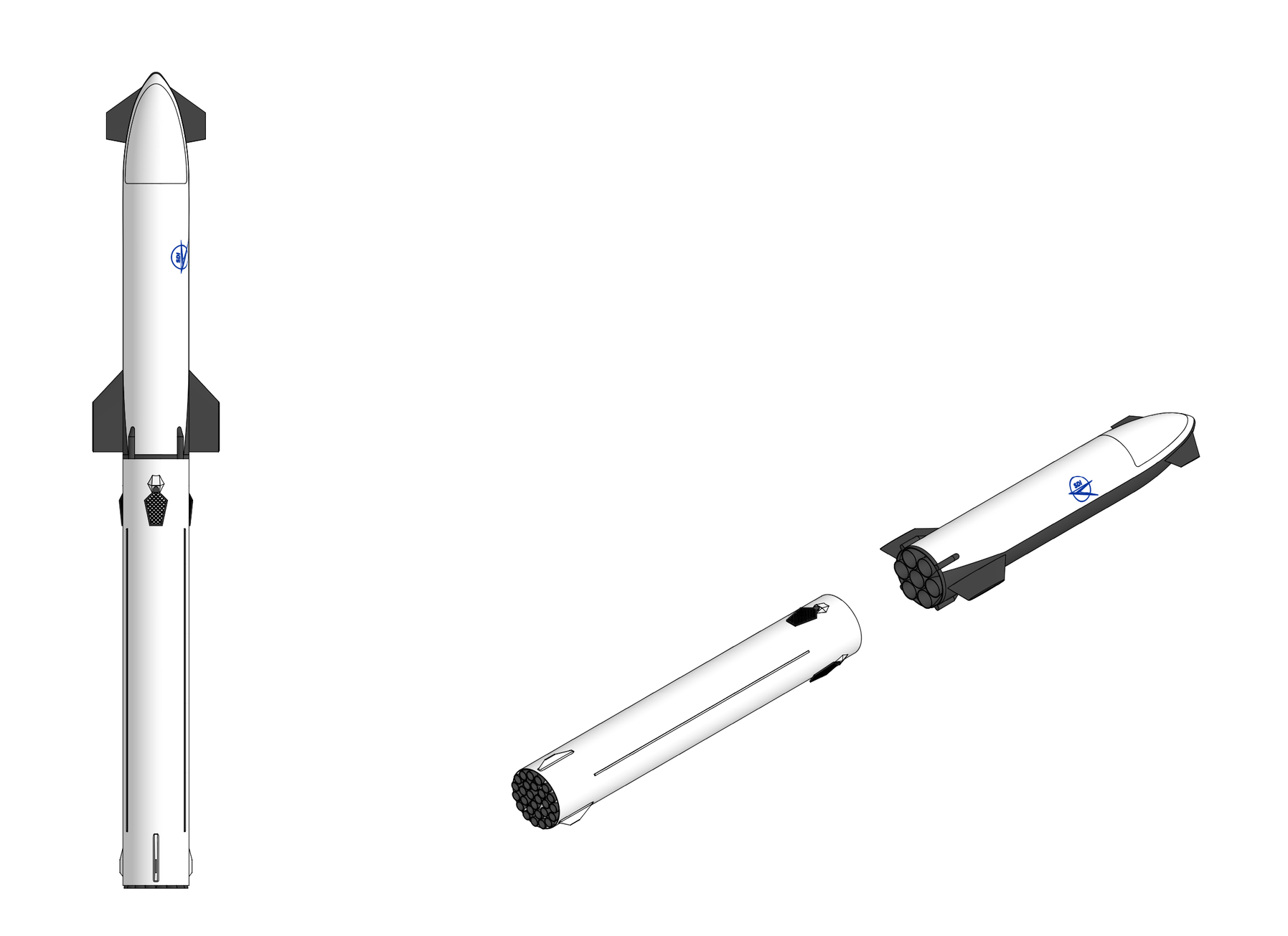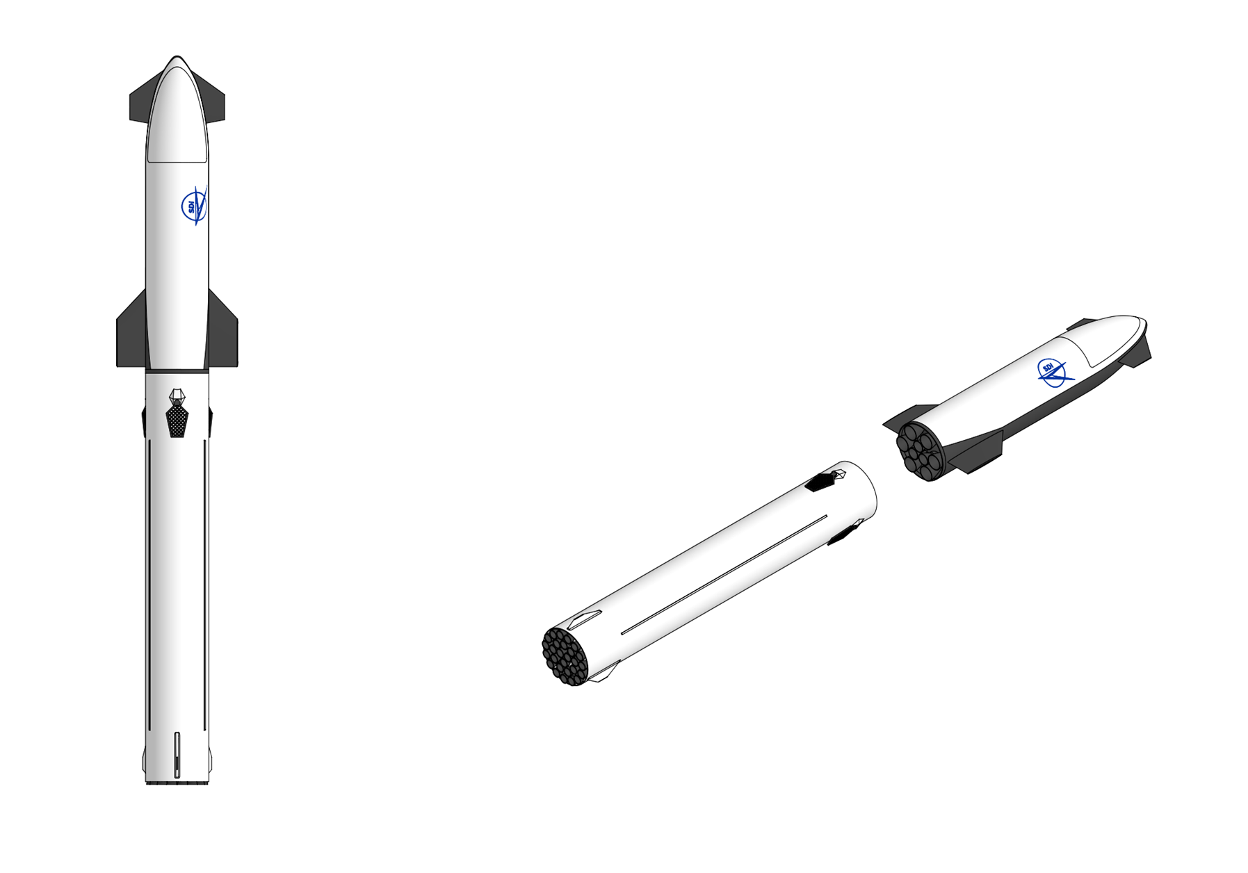
Colossus
General Characteristics:1st stage - Colossus Reusable Booster
- Function: Super Heavy Lift Reusable Launch Vehicle
- Height: 137.5 m
- Diameter: 12 m
- Mass: 10,400 t
- Payload to LEO:
320,000 kg (reusable)
560,000 kg (expendable)- Payload to GTO: 110,000 kg (reusable)
- Payload to TLI: 95,000 kg (reusable)
- Stages: 2
2nd stage - Colossus Spaceship
- Length: 77.5 m
- Diameter: 12 m
- Empty mass 260 t
- Gross mass: 7,850 t
- Engines: 28x SDI RM 4000
- Thrust: 142.8 MN (sl), 154.0 MN (vac)
- Specific Impulse: 305 sec (sl), 330 sec (vac)
- Fuel: LOX/RP-1
- Length: 60.0 m
- Diameter: 12 m
- Empty mass 270 t
- Gross mass: 1,870 t
- Engines: 9x SDI RM 2100
- Thrust: 27.45 MN (vac)
- Specific Impulse: 467 sec (vac)
- Fuel: LOX/LH2
Overview:
SDI's Colossus is a two stage, fully reusable orbital transportation system designed to deliver payloads in excess of 300 metric tonnes to low Earth orbit (LEO) in its baseline reusable configuration and over 550 metric tonnes fully expendable Both stages share a common 12.0 meter outer diameter and are constructed primarily from advanced intermediate-modulus carbon fiber reinforced polymer (CFRP) composite materials. The first stage, the Colossus booster, is powered by a cluster of 28 oxidizer rich staged combustion LOX/RP-1 engines while the second stage, the Colossus Spaceship, is powered by a cluster of 9 full flow staged combustion LOX/LH₂. Both stages are designed for autonomous propulsive vertical landing and rapid ground based turnaround. The vehicle is designed for a minimum operational life of 100 flights per booster airframe and Spaceship airframe before major depot level inspection and refurbishment. Turnaround time between flights is designed to not exceed 48 hours for the booster and 7 days for the ship under nominal conditions.
First Stage:The Colossus booster ise 77.5 meters in overall length and 12.0 meters in outside diameter and consists of from aft to forward, the aft skirt and thrust structure, RP-1 fuel tank, common bulkhead, LOX oxidizer tank, forward skirt, and interstage adapter.
Structure: The booster structure is constructed from graphite/epoxy composite using SDI's proprietary ICARUS (Innovative Composite Architecture for Reliable Unitary Structures) composite manufacturing technology. ICARUS uses seamless co-cured structural panels formed through-thickness stitching of dry composite preforms which are resin infused using controlled atmospheric pressure resin infusion and then cured in an out-of-autoclave process to create large, highly structurally efficient and damage tolerant composite structures which eliminate the need for mechanical fasteners and have significantly reduced part counts and fabrication and assembly times compared to conventional composite structures. ICARUS composite panels contain carbon fibers that are pre-kitted in multi-ply stacks with a 44/44/12 percent distribution of 0, 45, and 90° plies that are are used to build up the desired thickness and configuration. The panels are bi-directionally stiffened using unidirectional pultruded carbon rods to provide structurally efficient stiffening in one direction while foam-filled frames are positioned perpendicular to the rod-stiffeners to provide stiffening in the other direction. All stiffener flanges are stitched to the skin and no mechanical fasteners are used for joining. The integral stiffeners increases the structurally efficiency of each panel while the use of stitches instead of fasteners provides significantly more damage tolerance. ICARUS panels are created and cured entirely at atmospheric pressure and temperature, eliminating the need for curing ovens and autoclaves and allowing significantly larger composite structures to be created compared to legacy composite manufacturing methods. Each ICARUS panel is a unitized, integrally stiffened structural element composed of the following constituent parts: Skin: The skin is a multi-stack dry carbon fiber preform, typically composed of layers of warp-knit carbon fabric in a quasi-isotropic or tailored layup. Unlike prepreg laminates, the skin is assembled from dry (unresinized) fabric, which allows the through-thickness stitching needles to penetrate the full stack without the resistance and fiber damage that would occur in a pre-consolidated prepreg layup. Skin thickness is varied by adding or removing fabric layers at specific locations to accommodate local stress concentrations, pad-ups around penetrations, or tank dome transitions. The primary longitudinal stiffening elements are high-modulus carbon fiber pultruded rods, unidirectional carbon fiber rovings pulled through a die and consolidated with a thermoset resin matrix. These rods are laid into channels formed by folding the dry fabric skin and stitching it into a blade-stiffener (stringer) geometry. The pultruded rod sits at the top of the stringer blade, acting as the stringer cap. The rod is a continuous, unidirectional fiber element, which id designed to carry axial loads, the fiber volume fraction in a pultruded rod exceeding 60%, compared to approximately 55% for conventional prepreg tape, and the fibers are perfectly aligned with the load direction. The rod also serves as a crack arrest feature: because it is pre-cured and continuous, a skin crack or delamination that reaches the rod cannot propagate past it. Stitching: The entire assembly including skin, stringer flanges, frame flanges, and intercostals is stitched together using modified lock-stitch through-thickness stitching with Vectran (liquid crystal polymer) thread. Stitch rows are placed at a pitch of approximately 5.0 mm along stringer flanges and frame cap interfaces, and at a wider pitch of approximately 12.5 mm across the open skin bays. The through thickness stitches suppress delamination by mechanically bridging the interlaminar interfaces and enable the unitized co-cure of all structural elements (skins, stringers, frames) simultaneously as the stitches hold the dry preform together during resin infusion without the need for adhesive bonds. Stitches also arrest cracks and damage: impact damage that would propagate as a delamination in a conventional laminate is arrested at the stitch rows, confining the damage to a local bay between stringers. Transverse stiffening frames are integrated into the ICARUS panel by stitching preformed dry fabric frame caps and webs to the skin preform before resin infusion. The frames pass over the stringer blades through mouseholes, and the frame-to-skin and frame-to-stringer interfaces are stitched together, creating a continuous load path without mechanical fasteners. The completed dry preform including all skins, stringers, frames, pultruded rods, and stitching in place is placed in a matched metal tool (mold), vacuum bagged, and infused with a toughened epoxy resin system using controlled atmospheric pressurr resin film infusion (RFI). After infusion, the assembly is oven-cured at approximately 180 °C for 2 to 4 hours, depending on the resin system. The result is a fully consolidated, co-cured unitized panel in which all structural elements including skin, stringers, frames are integrated into a single monolithic part with no fasteners, no adhesive bonds, and continuous through-thickness reinforcement
The RP-1 fuel tank of the first stage booster is a cylindrical pressure vessel 12.0 meters in outside diameter and approximately 23.5 meters in barrel length, closed at each end by ellipsoidal domes. The tank holds approximately 2,100 tonnes of RP-1 kerosene at a maximum fill density of 820 kg/m³. The barrel section is fabricated as an ICARUS cylinder with integral blade-type longitudinal stringers (with pultruded rod caps, on approximately 200 mm pitch) and integral circumferential frames (hat-section profile, stitched to the inner skin surface, on approximately 600 mm pitch). The skin layup is a quasi isotropic schedule of IM7-class dry warp-knit carbon fabric, with a total skin thickness of approximately 8.5 mm in the mid-barrel region. Local pad ups increase the skin thickness to approximately 14 mm at the barrel-to-dome Y-joints where the membrane stress transitions from hoop-dominated (barrel) to meridional dominated (dome). The stringer blades are approximately 45 mm tall, with a 12 mm diameter pultruded rod cap. Each stringer runs the full length of the barrel section and terminates at a stitched runout at the dome transition. The stringers carry the axial compressive loads that arise during powered flight (the tank bottom carries the thrust loads from the engines, and the tank walls carry these loads upward to the forward structure) and during handling and transportation. Under internal pressure, the stringers are in tension along with the skin, and their contribution to hoop strength is modest but non-negligible. The frames serve as ring stiffeners that maintain the barrel's circular cross-section under bending loads, prevent shell buckling under axial compression, and provide hard points for the attachment of internal hardware (baffles, instrumentation, propellant management devices). The frames are co-cured with the skin, their flanges are stitched to the skin fabric with 3.2 mm pitch stitching before resin infusion. The forward and aft domes are curved ICARUS panels, six trapezoidal preform segments, each pre-stitched with meridional stiffeners and stitched together at the gore joints before infusion. The dome skin thickness varies from approximately 8.5 mm at the equator (matching the barrel) to approximately 12 mm at the crown, where the biaxial stress state transitions to equi-biaxial and the local curvature decreases (increasing the membrane stress). Each dome includes a polar boss consisting of a machined titanium alloy (Ti-6Al-4V) ring fitting co-cured into the dome apex that serves as the structural interface for propellant feed lines, pressurization lines, and instrumentation penetrations. The RP-1 tank interior includes anti-slosh baffles (perforated CFRP ring baffles at three stations along the barrel length), a propellant management device (PMD) at the aft dome consisting of a screened sump and vane array that ensures continuous liquid propellant delivery to the engine feed lines during all flight phases including low-g coast and vehicle maneuvering, and level sensors (capacitance probes) for propellant quantity gauging. Because RP-1 is not cryogenic and because the ICARUS construction does not experience cryogenic microcracking in the RP-1 tank, no metallic liner is required. A thin (0.08 mm) epoxy-based fuel-resistant coating is applied to the interior surfaces to prevent long-term chemical interaction between the RP-1 and the epoxy matrix, the coating also facilitating tank cleaning between flights as residual RP-1 and any decomposition products are flushed with a solvent wash and the coating prevents absorption of hydrocarbons into the composite matrix. The LOX tank is a cylindrical pressure vessel 12.0 meters in outside diameter and approximately 38.5 meters in barrel length and holds approximately 5,700 tonnes of liquid oxygen (tank volume approximately 5,000 m³). The LOX tank barrel features identical ICARUS construction as the RP-1 tank barrel with integral stitched stringers, frames, and co-cured skin, but with a thicker skin layup of approximately 11.0 mm in the mid barrel region, increasing to 18 mm at the dome Y-joints, the greater skin thickness reflecting the higher hydrostatic pressures at the base of the very tall LOX column. Stringer pitch is reduced to approximately 175 mm in the lower third of the barrel where axial compressive loads are highest, and frame pitch is reduced to 450 mm. The resin system uses for the LOX tank is a cryogenically toughened cyanate ester blend capable of resisting microcracking to at least 0.7% biaxial strain at 77 K. A thin PTFE (polytetrafluoroethylene) film liner (0.05 mm) is adhesively bonded to the tank interior as a secondary permeation barrier. PTFE is chemically inert with LOX and remains flexible at cryogenic temperatures. The liner does not carry structural load; it merely prevents any LOX that seeps through micro-damage in the composite from reaching the external insulation or the interstage cavity, where it could create a fire or explosion hazard in the presence of leaked fuel vapors. The LOX tank exterior is insulated with closed-cell PMI (Rohacell) foam panels, 25 mm thick, mechanically captured beneath a thin (1.0 mm) CFRP closeout skin. This insulation system limits LOX boil-off during ground hold (target boil-off rate less than 0.5% per hour and prevents atmospheric condensation and ice formation on the tank exterior, which could interfere with aerodynamic surfaces or create debris during ascent. The insulation is designed to be reusable and inspectable between flights, individual foam panels can be removed and replaced if damaged. The forward tank dome (upper) interfaces with the forward skirt. The aft tank dome (lower) interfaces with the common bulkhead. Both domes are ICARUS construction with meridional and circumferential stiffening, similar to the RP-1 tank domes but with the heavier skin gauges and cryogenic resin system appropriate for LOX service. The LOX tank includes anti-slosh baffles (five perforated ring baffles), a propellant management device at the aft dome, LOX level sensors, temperature sensors, and pressure transducers. The tank also houses the helium pressurization bottles consisting of 24 composite overwrapped pressure vessels (COPVs) containing high pressure helium for RP-1 tank pressurization. Submerging the helium COPVs in the LOX tank exploits the cryogenic temperature to densify the stored helium (helium density approximately triples from 300 K to 90 K at constant pressure), reducing the number and size of bottles required. Each COPV is a carbon/epoxy overwrap on an Inconel 718 liner, rated for 62 MPa service pressure, and is supported by titanium brackets stitched into the LOX tank barrel wall.
The common bulkhead separates the RP-1 tank from the LOX tank and is an oblate ellipsoidal surface with its convex side facing the LOX tank. The common bulkhead uses a foam core sandwich construction with two ICARUS face sheets (each approximately 5.5 mm thick) separated by a closed-cell polymethacrylimide (PMI) foam core approximately 65 mm thick. The foam core provides both structural depth (for bending stiffness) and thermal insulation. The ICARUS face sheets are stitched through-thickness, binding the entire sandwich together and preventing face-sheet delamination or disbond under the combined pressure and thermal loading. The common bulkhead is fabricated as a series of wedge-shaped segments each consisting of two pre-cut ICARUS fabric preforms with a precisely machined PMI foam core between them, stitched together and then assembled into the full dome shape on a concave mandrel tool. The gore joints are overlapped and stitched before resin infusion. The completed bulkhead preform is then infused with the cryogenic cyanate ester resin and oven-cured. The common bulkhead joins the barrel walls at a Y-joint ring where the RP-1 barrel, LOX barrel, and bulkhead all converge. The ring, a machined titanium alloy (Ti-6Al-4V) forging, is the most highly loaded structural element on the booster, carrying the combined hoop, axial, and pressure loads of both tanks plus the bulkhead shear loads. The Y-ring is bonded and stitched to the ICARUS barrel and bulkhead preforms before infusion, creating a co-cured metallic-composite joint. The tank pressurization system maintains adequate ullage pressure in both tanks to suppress propellant cavitation at the engine pump inlets and to maintain structural stability of the tank walls. LOX tank pressurization is autogenous, gaseous oxygen is tapped from the engine oxidizer preburner exhaust gas path via a heat exchanger that cools the oxygen-rich gas (from approximately 810 K down to 300 K) and routes it to the LOX tank ullage through a diffuser at the forward dome. The pressurization flow rate is regulated by a closed-loop controller that monitors ullage pressure and modulates a flow control valve. Target ullage pressure is 0.38 MPa. RP-1 tank pressurization uses heated helium. Cold helium from the COPVs submerged in the LOX tank is routed through a heat exchanger in the engine exhaust stream, warming it to approximately 350 K, and then injected into the RP-1 tank ullage through a diffuser at the forward dome (which is the common bulkhead's RP-1 facing surface). Target ullage pressure is 0.28 MPa. The lower pressure compared to the LOX tank ensures that the common bulkhead always experiences a net pressure load from the LOX side, which keeps the bulkhead in the correct deflection direction. A relief valve on the RP-1 tank prevents the RP-1 ullage from exceeding the LOX ullage pressure minus a 0.05 MPa margin
LOX and RP-1 propellant is fed fed to the engines via three downcomers. LOX exits the aft dome of the LOX tank through two 600 mm diameter feedlines which route through the RP-1 tank interior through insulated tunnels and through the common bulkhead, exiting at the aft dome of the RP-1 tank. Below the RP-1 tank, the two feedlines merge into a toroidal LOX manifold mounted on the upper ring frame of the thrust structure. From the manifold, 28 individual branch lines (one per engine) deliver LOX to each engine's low-pressure oxidizer turbopump inlet. All LOX feed lines are vacuum-jacketed where they transit the RP-1 tank interior to minimize heat transfer. The feedlines are fabricated from Inconel 718 for cryogenic compatibility and structural integrity. Bellows joints accommodate differential thermal contraction between the cryogenic LOX lines and the surrounding structure. Isolation valves at the manifold and at each engine inlet allow individual engines to be isolated in the event of a downstream leak or engine anomaly without affecting the remaining engines. RP-1 exits the aft dome of the RP-1 tank through a single 500 mm diameter feedline and enters a toroidal fuel manifold on the thrust structure. From the manifold, 28 branch lines deliver RP-1 to each engine's low-pressure fuel turbopump inlet. Propellant is loaded through ground side umbilical connections at the base of the vehicle. The RP-1 loading rate is approximately 6,000 liters per minute through a single 200 mm fill/drain line while the LOX loading rate is approximately 18,000 liters per minute through two 250 mm fill/drain lines. Total propellant loading time from start to flight ready is approximately 3.5 hours with LOX loading occurring last to minimize boiloff. After landing residual propellant is drained through the same fill/drain lines and residual RP-1 is recycled after filtration and testing while residual LOX is vented to atmosphere. The tanks are then purged with gaseous nitrogen (RP-1 tank) or gaseous helium (LOX tank) to inert the interior before maintenance access.
The thrust structure is the primary load bearing assembly that transmits the combined thrust of 28 RM 4000 engines into the aft dome and barrel of the RP-1 tank. The thrust structure consists of a conical ICARUS shell reinforced by four Ti-6Al-4V titanium alloy ring frames at axial intervals of approximately 1.2 m. The ring frames are machined forgings, each approximately 350 mm deep (radially) and 25 mm thick, with integral pad-ups at the 28 engine mount locations. Each of the 28 engines is mounted on an individual gimbal block consisting of a spherical bearing housing machined from 17-4PH precipitation-hardened stainless steel that is bolted to a reinforced pad on the lowest titanium ring frame. The gimbal allows ±7° deflection of the engine in two axes. Each gimbal block mounting location is designed for a maximum load of approximately 6,100 kN (the 105% rated thrust of a single RM 4000 plus dynamic loads and safety factor). The thrust structure also provides the mounting provisions for the two electromechanical thrust vector control (TVC) actuators per gimbaling engine (48 actuators total for the 24 gimbaling engines), the engine propellant inlet manifolds, the engine purge and drain lines, and the engine health management sensor harnesses. The aft skirt is a cylindrical ICARUS shell approximately 5.8 meters in total length and 12.0 meters in diameter that extends below the RP-1 tank aft dome and encloses the engine bay. The aft skirt serves as the structural interface between the tank and the thrust structure, and carries the aft thermal protection system. The aft skirt ICARUS construction uses a heavier skin gauge (approximately 12 mm) and tighter stringer pitch (approximately 150 mm) than the tank barrel, reflecting the high axial compressive loads during powered flight and the combined bending and axial loads during the landing impact. During atmospheric reentry, the aft end of the booster (which leads during the engine first descent) is exposed to moderate aerodynamic heating. The aft dome and the outer surface of the aft skirt are protected by a reusable ablative TPS consisting of a cork-silicone composite approximately 8 mm thick, applied as preformed tiles bonded to the ICARUS outer surface. This material ablates slowly during the reentry heat pulse, protecting the underlying composite structure to a maximum temperature of approximately 180 °C (well within the capability of the cured epoxy resin). The ablative tiles are inspected after each flight and replaced as needed, typically every 5–10 flights. The forward skirt is a short (3.0 m) cylindrical ICARUS shell that connects the LOX tank forward dome to the interstage adapter. and provides the structural transition between the pressurized tank structure and the unpressurized interstage, houses the forward avionics bay (containing flight computers, navigation systems, telemetry transmitters, and power distribution electronics), and provides mounting points for the four grid fin actuator assemblies. The avionics bay is an annular, environmentally sealed compartment approximately 1.2 meters deep, accessed through removable ICARUS panels for ground maintenance. The electronics are mounted on cold plates cooled by a circulating fluid loop that rejects heat to a radiator panel on the vehicle exterior. The avionics bay is pressurized to approximately 0.1 MPa (1 atm) with dry nitrogen to prevent condensation on the electronics during cryogenic propellant loading. The interstage adapter is a cylindrical ICARUS shell 12.0 meters in diameter and 6.5 meters in length that structurally connects the booster to the ship and transmits the ship's weight (approximately 2,000 tonnes at liftoff) into the booster's forward skirt and LOX tank. The interstage remains with the booster after stage separation. The interstage ICARUS construction uses a skin thickness of approximately 10.0 mm with integral stringers on 200 mm pitch and frames on 500 mm pitch. The ship-to-interstage interface uses a system of 12 pneumatic separation fittings equally spaced around the circumference at the upper end of the interstage. Each fitting consists of a collet mechanism that grips a mating ring on the ship's aft skirt. At the staging command, all 12 collets are simultaneously released by firing pyrotechnic gas generators that pressurize the collet release cylinders. Pusher springs at each fitting provide an initial separation velocity of approximately 1.5 m/s to move the ship clear of the interstage before the ship's engines are ignited. The separation system is fully redundant: any 8 of the 12 collets releasing is sufficient for clean separation. Three deployable grid fins provide aerodynamic control authority during the booster's unpowered atmospheric descent from approximately 70 km altitude to the landing burn initiation altitude. Each grid fin is a lattice structure approximately 4.5 meters in span and 3.0 meters in chord fabricated from a titanium alloy (Ti-6Al-4V) lattice core with ICARUS composite face skins that provide smooth aerodynamic surfaces and additional stiffness. Each grid fin is mounted on a hinge mechanism at the top of the forward skirt and is actuated by a dual-redundant electromechanical actuator capable of deflecting the fin ±25° at rates up to 20°/s. The fins are stowed flat against the interstage outer surface during ascent to minimize drag and deployed to the perpendicular position after stage separation. The deployment mechanism uses a spring-loaded overcenter linkage with a pyrotechnic release. Grid fins generate lift and drag forces that can be differentially modulated to steer the booster during its descent. The aerodynamic center of pressure of the deployed grid fins is forward of the vehicle's center of gravity, providing stable aerodynamic trim in the engine-first descent attitude.
Avionics: The booster avionics system employs a triple redundant flight computer system housed in the forward avionics bay. Each flight computer unit (FCU) is a radiation tolerant multi core processor (approximately 50 GFLOPS) running a real time operating system with a hypervisor based partitioning architecture that isolates safety critical GNC functions from mission-management and telemetry functions. The flight computers interface with the engine digital controllers, grid fin actuators, landing leg deployment system, and navigation sensors via a deterministic time-triggered Ethernet (TTE) data bus with redundant physical layers (dual optical fiber rings). The TTE bus provides guaranteed worst-case message latency of less than 1 ms, which is essential for real-time control of the 28-engine thrust vector control system. The booster's navigation system provides position, velocity, and attitude data throughout all flight phases, including the post-separation descent and landing. Three ring laser gyroscope (RLG) based IMUs are mounted on a rigid bench in the forward avionics bay and provides three-axis angular rate and three-axis linear acceleration data at 400 Hz. The IMUs are calibrated and aligned before each flight using a ground-based optical alignment system. Dual-redundant multi-constellation GNSS receivers provide position and velocity updates at 10 Hz. GNSS data is tightly coupled with the IMU data in an extended Kalman filter to provide a navigation solution with approximately 2-meter position accuracy and 0.05 m/s velocity accuracy during all non-blackout flight phases. During the final approach and landing phase (below approximately 3 km altitude), the GNSS/INS solution is augmented by a terrain-relative navigation (TRN) system consisting of a scanning LiDAR (operating at 1064 nm, with a scan rate of 20 Hz and a range of 5 km), two wide-angle optical cameras (visible and near-infrared), and a radar altimeter (operating at 4.3 GHz, providing altitude data from 5,000 m to 0.5 m). The LiDAR and camera data are processed by a dedicated vision processor that matches observed surface features against a pre-loaded digital elevation model of the landing site, providing sub-meter position accuracy independent of GNSS. The radar altimeter provides height-above-ground data with approximately 0.3 m accuracy for the final seconds of the landing.
Electrical: The booster's electrical power system provides 270 VDC power to all avionics, actuators, instrumentation, and pyrotechnic systems. Two lithium-ion battery packs (each approximately 45 kWh capacity) provide primary electrical power for the entire flight, including the post-separation descent and landing. The battery packs are housed in a temperature-controlled enclosure in the aft skirt and are sized for a worst-case mission duration of 30 minutes (liftoff through landing). Total average power draw during flight is approximately 85 kW, driven primarily by the grid fin actuators (40 kW peak during aggressive maneuvering), engine TVC actuators (25 kW), avionics and flight computers (12 kW), and instrumentation and telemetry (8 kW). During ground operations, the vehicle is powered by ground-supplied 270 VDC through umbilical connectors at the base. The batteries are maintained at full charge until T−2 minutes, when the vehicle transitions to internal power.
Telemetry: For Telemetry the booster carries S-band (2.2 GHz) and C-band (5.8 GHz) telemetry transmitters that downlink real time housekeeping data (approximately 10 Mbit/s) to ground receiving stations throughout the flight. A UHF command receiver provides a backup command uplink capability for range safety purposes. For post landing operations, a Wi-Fi (802.11ax) transceiver provides ground crew data access within the landing zone.
First Stage Propulsion:The first stage of Colossus is powered by a total of 28 SDI RM 4000 oxidizer-rich staged combustion (ORSC) LOX/RP-1 engines with a total sea-level thrust of 142,800 kN. The RM 4000 engine is designed to produce 5,100 kN of sea-level thrust at a chamber pressure of approximately 26 MPa, with a specific impulse of approximately 305 seconds at sea level and 330 seconds in vacuum. The engines are mounted in three concentric rings: 3 engines in the center ring gimbaled ±7°, 10 engines in the intermediate ring, gimbaled ±7°, and 15 engines in the outer ring (fixed, non gimballed). This arrangement provides full six-degree-of-freedom thrust vector control authority and engine-out tolerance at any point in the flight (the vehicle can lose up to 3 engines and still complete its mission). Each RM 4000 engine is mounted on a gimbal bearing that allows angular deflection of ±7° in two orthogonal axes (pitch and yaw). The gimbal bearing is a spherical, self-aligning flexure design fabricated from 17-4PH stainless steel. Gimbal actuation is provided by two electromechanical actuators (EMAs) arranged orthogonally, each capable of slewing the engine at rates up to 15°/s. The EMAs are powered by the vehicle's 270 VDC electrical bus and controlled by commands from the vehicle flight computer via the engine digital controller. Flexible propellant ducts (bellows assemblies) at the engine inlet accommodate the angular displacement of the engine relative to the fixed vehicle propellant manifolds. These bellows are fabricated from Inconel 625 and are qualified for the full range of gimbal motion at operating pressure
- Name: SDI RM 4000
- Type: Liquid-fuel engine
- Propellant: LOX/RP-1
- Mixture Ratio: 2.7:1
- Cycle: Oxidizer-rich staged combustion
- Length: 3,800 mm
- Diameter: 1,900 mm
- Dry Weight: 5,400 kg
- Nozzle Ratio: 25:1
- Thrust (vac):5,500 kN
- Thrust (sl): 5,100 kN
- Throttle Range: 100% to 40%
- Thrust-to-weight ratio: 97:1
- Chamber Pressure: 26.0 MPa
- Isp (vac): 330 seconds
- Isp (sl): 305 seconds
The RM 4000 engines operates in several distinct modes during a Colossus booster mission. During ignition and ramp-up (T−3.2 s to T+0) each engine executes its automated start sequence, ramping from ignition to approximately 90% thrust over 3.2 seconds. All 28 engines are ignited in a staggered sequence (3 center engines first, then intermediate ring, then outer ring, at 200 ms intervals) to limit the rate of thrust onset and reduce structural transient loads on the launch mount. During ascent (T+0 to BECO) all 28 engines operate at 100–105% thrust. As the vehicle ascends and atmospheric pressure drops, the engines experience a natural increase in effective nozzle performance and the thrust rises from 5,100 kN (sea level) toward 5,500 kN (vacuum) per engine. Late in the burn, as propellant mass depletes, the engines are be throttled down to maintain the vehicle's axial acceleration below 4.0 g. Following stage separation, 9 center and intermediate ring engines are reignited at approximately 75% thrust to reverse the booster's downrange velocity and redirect its trajectory back toward the launch site. This burn lasts approximately 37 seconds and consumes approximately 140 tonnes of propellant. At approximately 45 km altitude during descent, the 3 center engines are ignited at approximately 60% thrust for a brief (8–12 s) reentry burn that reduces the booster's velocity before it encounters peak aerodynamic heating and loading. This burn also creates a "virtual nose cone" of exhaust gas ahead of the vehicle that partially shields the aft structures from reentry heating. For the landing burn A single center engine is ignited at 40% thrust for the final precision landing burn, beginning at approximately 500 m altitude and lasting 10–15 seconds. The deep throttle capability (40%) is essential because even a single RM 4000 engine at full thrust produces 5,100 kN — far exceeding the weight of the nearly empty booster (~270 tonnes, or ~2,650 kN). At 40% thrust (2,040 kN), the engine is still producing a thrust-to-weight ratio less than 1.0 on the empty booster, requiring a precisely timed "hoverslam" profile, the engine ignites at a calculated altitude such that the vehicle reaches zero velocity at zero altitude.
Second Stage:The Colossus Spaceship is the second stage of the Colossus launch vehicle and is designed to transport cargo to Earth orbit, the Moon, and Mars. The Spaceship is 60 meters in overall length and 12.0 meters in outside diameter and consists of from aft to forward the aft skirt and engine bay, LOX oxidizer tank, common bulkhead, LH₂ fuel tank, payload bay, and nose fairing. Like the booster the Spaceship is designed to be reusable and capable of landing propulsively by firing its engines to perform a controlled descent into the arms of a tower or with landing legs on other planetary bodies. The windward side of the vehicle is protected by a heat shield consisting of hexagonal black tiles that can withstand temperatures of 1,600 °C, designed to protect the vehicle during atmospheric entry and to be used multiple times with minimal maintenance between flights.
Structure: All primary structure of the Spaceship is ICARUS carbon fiber composite construction except the nose cap RCC structure and the TPS tiles. The Spaceship LH₂ tank is the largest structural element of the ship with a barrel length of approximately 18.5 meters and a total volume of approximately 3,750 m³ and holds approximately 270 tonnes of liquid hydrogen propellant. The LH₂ tank features an internal Vitreloy 105 amorphous metallic glass liner which provides a fully dense, zero-porosity permeation barrier. The liner is applied as a continuous foil produced by planar flow casting. Foil strips are laid onto the ICARUS tank interior in overlapping courses and ultrasonically seam-welded at the overlaps, producing a continuous, hermetic envelope. The liner is then adhesively bonded to the composite substrate using a cryogenically flexible polyurethane adhesive. The exterior insulation system consists of 50 mm of closed-cell PMI foam covered by a 1.5 mm CFRP closeout skin. This provides a thermal conductance of approximately 0.6 W/m²·K, limiting the total heat leak into the LH₂ tank to approximately 85 kW during ground hold. At this heat leak rate, the LH₂ boil-off rate is approximately 0.38 tonnes per hour, which is managed by continuous replenishment from the ground supply until T−60 seconds and by pressure relief through the tank vent valve during ascent. The insulation system is subdivided into modular panels (approximately 1.5 m × 1.0 m each) that are mechanically fastened to the ICARUS tank exterior using composite Z-pins bonded to the tank outer skin. The modular design is intended to allow individual panels to be removed and replaced during ground turnaround without disturbing adjacent panels or the tank structure. Each panel is edge-sealed with silicone gaskets to prevent atmospheric gas from condensing in the insulation foam and degrading its thermal performance. The LH₂ tank features autogenous pressurization using gaseous hydrogen tapped from the engine fuel-rich preburner exhaust through a heat exchanger. Target ullage pressure is 0.25 MPa. During coast phases, the LH₂ tank is pressurized by gaseous hydrogen produced by an electric resistance vaporizer that boils a small quantity of stored LH₂, eliminating the need for helium storage on the ship, simplifying the pressurization system and reducing mass.
The LOX tank is positioned aft below the LH₂ tank, placing the heavier fluid closer to the engines for favorable center of gravity management. The barrel length is approximately 9.5 meters and the total volume approximately 1,405 m³, holding approximately 1,600 tonnes of LOX. The LOX tank barrel uses the same ICARUS construction and cyanate ester resin as the booster's LOX tank. Stringer pitch is 200 mm; frame pitch is 550 mm. The PTFE film liner (0.05 mm) is applied to the interior as on the booster. The LOX tank uses 25 mm of exterior PMI foam insulation, identical to the booster. The aft dome's exterior insulation transitions into the thermal protection system at the aft skirt interface. The Spaceship's common bulkhead separates the LOX tank (aft, approximately 90 K) from the LH₂ tank (forward, approximately 20 K). The common bulkhead construction consists of ICARUS face sheets stitched through a PMI foam core, fabricated in gore segments, and infused with cyanate ester resin. The bulkhead is convex toward the LOX tank (the higher-pressure tank) and the structural arrangement ensures the LOX ullage pressure always exceeds the LH₂ ullage pressure. The LOX tank features autogenous pressurization using gaseous oxygen tapped from the engine oxidizer-rich preburner exhaust through a heat exchanger. Target ullage pressure is 0.35 MPa. During coast phases when the engines are not operating, the LOX tank is pressurized by a small stored quantity of gaseous helium in COPVs.The Spaceship's thrust structure transmits the thrust of 9 RM 2100 engines (27,450 kN total at full vacuum thrust) into the LOX tank aft dome and consists of a conical ICARUS shell with a single heavy titanium ring frame at the engine mounting plane. Each RM 2100 engine is mounted on a gimbal block bolted to the titanium ring frame, with ±6° gimbal freedom in two axes.
Thermal Protection System: As the Spaceship reenters the atmosphere from orbital velocity (approximately 7.8 km/s) it experiences a peak heating rate of approximately 400 kW/m² at the windward centerline and peak surface temperatures exceeding 1,650 °C on the forward windward surface. The windward side is this protected by a thermal protection system (TPS) composed of several thousand hexagonal black tiles constructed from Reinforced Carbon-Carbon (RCC) and Carbon fiber reinforced Silicon Carbide (C/SiC) ceramic matrix composite. The nose cap experiences the most severe heating (stagnation point heat flux approximately 800 kW/m², temperature approaching 2,000 °C) and is fabricated from reinforced carbon-carbon (RCC) consisting of a woven carbon fiber preform infiltrated with pyrolytic carbon via chemical vapor infiltration (CVI). The RCC nose cap is is approximately 2.5 meters in diameter and is mechanically attached to the ICARUS nose fairing structure through a titanium alloy interface ring with ceramic standoff insulators that limit conductive heat transfer into the composite substrate. The entire windward surface from the nose cap aft to the body flaps is protected by fourth-generation C/SiC ceramic matrix composite (CMC) tiles. These tiles are melt-infiltrated (MI) carbon fibers in a silicon carbide matrix, produced in hexagonal panels approximately 300 mm × 300 mm × 12 mm thick. Each tile includes an integral environmental barrier coating (EBC) of ytterbium disilicate (Yb₂Si₂O₇) applied by atmospheric plasma spray, which protects the C/SiC from oxidative recession at temperatures up to 1,700 °C.The C/SiC CMC tiles are mechanically fastened to the ICARUS airframe through metallic attachment fittings with ceramic fiber insulation blankets (alumina felt, approximately 30 mm thick) between the tile and the substrate. The insulation blankets limit the heat conducted to the ICARUS substrate to approximately 200 °C, within the composite's temperature capability. Each tile is individually removable without disturbing adjacent tiles, enabling targeted replacement of damaged tiles during ground turnaround. The leeward and lateral surfaces experience lower peak temperatures of approximately 650–900 °C) and are protected by flexible ceramic insulation blankets composed of alumina-boria-silica (ABS) fiber quilted between an outer fabric of woven alumina and an inner fabric of woven glass. The blankets are approximately 20 mm thick and are bonded to the ICARUS outer skin with RTV silicone adhesive. The blankets are designed to be reusable for at least 100 missions at temperatures up to 800 °C. After each flight, the TPS is inspected using a combination of automated robotic scanning involving a gantry-mounted robotic arm with thermographic cameras and ultrasonic probes that scans the entire windward surface and manual inspection of flagged areas. The CMC tiles are inspected for cracking, spalling of the EBC, and mechanical damage from micrometeoroid or orbital debris (MMOD) impact. Tiles with damage exceeding defined accept/reject criteria are replaced. Approximately 2–5% of windward tiles are expected to require replacement after each mission.
Aerodynamic Control: Two aft body flaps are mounted at the base of the aft skirt, 180° apart, on the windward (belly) side and leeward (dorsal) side of the vehicle. Each body flap is a large aerodynamic control surface approximately 6.0 meters in span and 3.5 meters in chord (root), fabricated as an ICARUS structure with a SiC/SiC ceramic matrix composite (CMC) leading edge and a CMC hot-surface skin on the windward face. The body flap interior uses PMI foam core between the ICARUS structural spar and rib framework. Each body flap is actuated by two redundant electromechanical actuators (EMAs), each rated for 450 kN·m of hinge moment. The EMAs are powered by the vehicle's lithium ion battery system and receive commands from the flight computer at 100 Hz update rate. Maximum flap deflection is +30° (trailing edge toward belly) and −15° (trailing edge toward back). The flaps provide pitch and roll control during atmospheric reentry and subsonic flight. Two forward canard surfaces are mounted on the ship's payload bay section, approximately 3.0 meters aft of the nose fairing/payload bay junction. The canards are trapezoidal planforms approximately 4.0 meters in spanand 2.5 meters in root chord, fabricated as ICARUS structures with Carbon fiber reinforced Silicon Carbide (C/SiC) CMC leading edges and windward skins. Each canard is actuated by a single EMA rated for 250 kN·m hinge moment, and deflects ±30°. The canards provide pitch control authority that, combined with the aft body flaps, allows the vehicle to modulate its angle of attack and aerodynamic lift during the hypersonic and transonic phases of reentry. By differentially deflecting the two canards, roll control is achieved. The canards are designed to withstand temperatures up to 1,600 °C on their windward surfaces during reentry.
Payload Bay: The payload bay is a cylindrical ICARUS shell section approximately 12.0 meters in inside diameter and 20.0 meters in usable length located between the forward dome of the LH₂ tank and the aft end of the nose fairing with an enclosed, environmentally controlled volume of approximately 2,000 m³/ The payload bay ICARUS structure features integral payload support fittings are co-cured into the ICARUS frames at standardized locations, providing a grid of hard points to which payload adapters, trunnion fittings, or custom cradles can be attached. The payload bay is equipped with an air circulation and temperature management system that maintains the interior at 10 to 35 °C during ground operations and ascent. For payloads with active thermal management requirements (e.g., cryogenic propellant cargo, biological payloads), dedicated thermal control interfaces including cold plates and fluid quick-disconnect coupling) are available at the payload support fittings. The payload bay is vented to vacuum through one-way vent valves during ascent, reaching orbital vacuum conditions at approximately T+200 seconds. Payload deployment is accomplished through a pair of clamshell-type doors on the fairing's leeward side, each approximately 15.0 meters long and 5.0 meters wide. The doors are hinged along the vehicle's windward-to-leeward meridian and open outward by approximately 120° using electric motor-driven hinge mechanisms. The doors are closed and latched before deorbit and reentry. The door hinge mechanisms and perimeter seals are designed for 50+ open/close cycles. The door seals are a dual-redundancy design with a primary spring-loaded Inconel metallic seal backed by a secondary ceramic rope seal. Both seals are designed to survive the reentry heating environment without breach.
Avionics: The Spaceship carries a triple redundant flight computer system mostly identical to the booster's but with additional software capability for orbital operations including orbital rendezvous and proximity operations guidance, autonomous docking navigation, and payload deployment sequencing. The flight computers are housed in an avionics bay in the payload bay section, protected from reentry heating by the surrounding ICARUS structure and a local insulation blanket. The Spaceship's navigation system is an enhanced version of the booster's, with the addition of a star tracker for stellar-inertial attitude determination during orbital operations and a relative navigation sensor suite for rendezvous and docking missions including a flash LiDAR and cooperative target tracker operating at ranges from 10 km to 1 m. During reentry, the vehicle experiences a communications and GNSS blackout of approximately 3 to 5 minutes (from approximately 85 km to 45 km altitude) due to plasma formation around the vehicle. During this period the navigation system relies on the IMUs with estimated position error growth of approximately 300 meters over the blackout duration. Upon GNSS reacquisition the navigation filter converges to normal accuracy within approximately 15 seconds.
Electrical: The Spaceship's electrical power system is more capable than the booster's, reflecting the longer mission duration of up to several days for orbital operations and the higher total energy requirement. Primary power during ascent and reentry is provided by a bank of three proton-exchange membrane (PEM) hydrogen-oxygen fuel cells. The fuel cells consume the same hydrogen and oxygen carried in the ship's main propellant tanks, eliminating the need for dedicated energy storage reactants. The Spaceship carries three identical PEM fuel cell stacks, arranged in a two-out-of-three redundancy configuration (any two stacks can supply the full vehicle power demand; the third is a hot standby). Each stack is a self-contained module approximately 800 mm long, 500 mm wide, and 400 mm tall, with a dry mass of approximately 85 kg. Each fuel cell stack comprises 400 individual cells connected electrically in series to produce a nominal output voltage of approximately 280 VDC. The three fuel cells provide a total of 120 kW of power. Fuel cell waste heat (up to 70 kW at full three-stack operation) is removed by a pumped-fluid thermal management loop. Deionized water with 40% ethylene glycol circulates through the bipolar plate cooling channels at approximately 3 liters per minute per stack, absorbing heat and carrying it to the radiator panels. Two radiator panels are mounted on the ship's leeward (dorsal) surface, each approximately 4.5 m² of active area with aluminum-ammonia heat pipe construction. During orbital operations, the radiators reject heat to space by radiation. During atmospheric flight, the radiators are partially shielded by the AFRSI thermal blankets which are designed with a higher emissivity outer surface at the radiator locations, and supplemental heat rejection is provided by the fuel cell product water, which carries waste heat when dumped overboard. A single lithium-ion battery pack (approximately 15 kWh capacity, 75 kg mass) is carried as a supplemental energy buffer and emergency power source. The battery handles transient loads that exceed the fuel cells' ramp rate (the fuel cells can increase output at approximately 5 kW/s; the battery covers the gap during faster transients, such as sudden actuator demands). The battery also provides approximately 20 minutes of emergency power at minimum loads (4.5 kW) in the event of a complete fuel cell shutdown, sufficient to maintain avionics and communication while the crew (if present) evaluates options.
Second Stage Propulsion:The Colossus Spaceship stage is powered by a total of nine SDI RM 2100 engines. The engine arrangement consists of an outer ring of six six vacuum-optimized RM 2100 engines (ε = 180:1), and an inner ring of three lower-expansion-ratio RM 2100 engines (ε = 60:1)for in-space maneuvering as well as during descent and landings. The three sea level RM 2100 engines are mounted in a gimbaled inner ring and serve as the ship's primary maneuvering and landing propulsion, and ignite for the deorbit burn, reentry braking (if required), and the final landing burn. The six vacuum RM 2100 engines are mounted in a fixed non gimbaled outer ring and operate only during the primary ascent burn and, optionally, major orbital maneuvers. They are never ignited in the atmosphere. The RM 2100 engine which powers the Colossus Spaceship stage is an advanced full flow staged combustion cycle engine burning liquid oxygen and liquid hydrogen. Each RM 21000 sea level engine is mounted on a two-axis gimbal bearing that allows angular deflection of ±8° in pitch and yaw. The gimbal bearing is a spherical, self-aligning flexure joint fabricated from 17-4PH precipitation-hardened stainless steel, with a Teflon impregnated fiber composite bearing surface that provides low-friction articulation without lubrication. The gimbal bearing transmits the full engine thrust load through the spherical interface into the thrust structure ring frame. Gimbal actuation is provided by two electromechanical actuators (EMAs) arranged orthogonally (one pitch, one yaw) on each engine. Each EMA consists of a brushless DC motor, a planetary gear reduction (approximately 200:1), and a ball-screw linear actuator, packaged in a sealed, pressurized housing to prevent hydrogen intrusion. The EMAs are rated for a continuous force of 65 kN and a peak force of 95 kN, providing adequate authority to gimbal the engine against the aerodynamic and inertial loads encountered during the landing maneuver. Maximum slew rate is 15°/s, and the actuator bandwidth (−3 dB) is 12 Hz, providing responsive thrust vector control for the precision landing phase. Flexible propellant inlet ducts consisting of multi-ply Inconel 625 bellows with internal flow liners accommodate the angular displacement between the gimbaling engine and the fixed propellant manifolds. The deep throttle capability (down to 20%) is required for the precision landing burns, where the ship's mass has been substantially reduced by propellant consumption. The RM 2100 engine operational modes consist of orbital insertion burn, the deorbit burn, and the landing burn. During the orbital insertion burn all 9 engines operate at 100% thrust for the primary ascent burn following stage separation, lasting approximately 370 seconds. Late in the burn engines are throttled to maintain acceleration below 4.0 g. For the deorbit burn one to three engines fire at 50–80% thrust for a brief retrograde burn (delta-v approximately 100–150 m/s) to lower the ship's perigee into the atmosphere. Duration is approximately 30 ro 60 seconds depending on payload mass. For the landing burn one to three engines center fire at 20–50% thrust for the final powered landing maneuver. At 20% thrust, a single RM 2100 produces 660 kN, still a substantial force but manageable for the ship's landing mass of approximately 140 to 200 tonnes (depending on whether payload has been delivered). The deep throttle capability to 20% is achieved through a combination of reduced preburner temperatures (lowering turbine power), partially closed main propellant valves (reducing flow rates), and modified injection element geometry. At 20% thrust, combustion stability is maintained by the gas-gas injection architecture, which does not suffer from the atomization and mixing degradation that traditionally plagues liquid injection at low flow rates. During the ascent the ship can lose any 2 of its 9 engines during the ascent burn and still reach orbit with reduced payload. If one vacuum engine is lost, the diametrically opposite vacuum engine is throttled to approximately 60% to maintain thrust symmetry, and the three sea level ngines compensate for the reduced total thrust. If one sea level engine is lost, the remaining two sea level engines provide TVC authority, and the flight computer recalculates the optimal trajectory to orbit. If two vacuum engines are lost (non-adjacent), the remaining four vacuum engines and three BSL engines can complete the insertion burn with a payload penalty of approximately 30 to 45 tonnes. During the landing phase The ship can lose one of three sea level RM 2100 engines during the landing burn and complete a safe landing on two engines with increased throttle. Loss of two RM 2100 engines during landing is survivable only if the remaining single engine can achieve a thrust-to-weight ratio above 1.0 at its maximum throttle (2,870 kN vacuum / approximately 2,440 kN sea-level), which is possible if the ship's landing mass is below approximately 245 tonnes. The probability of losing two of three engines during a landing burn of 12–18 seconds duration is extremely low (estimated at less than 10⁻⁸ per landing), given the RM 2100 design reliability.
- Name: SDI RM 2100
- Type: Liquid-fuel engine
- Propellant: LOX/LH-2
- Mixture Ratio: 6.0:1
- Cycle: full-flow staged combustion
- Length: 4,500 mm
- Diameter: 2,500 mm
- Dry Weight: 3,100 kg
- Nozzle Ratio: 60:1
'- Thrust (sl):3,050 kN
- Thrust (vac):3,300 kN
- Throttle Range: 100% to 65%
- Thrust-to-weight ratio: 100:1
- Chamber Pressure: 30 MPa
*[]Isp (sl: 394 seconds- Isp (vac): 467 seconds
For orbital maneuvering the Spaceship carries a gaseous oxygen/gaseous hydrogen reaction control system (RCS) with 16 thrusters arranged in four pods of 4 thrusters each (two pods forward on the payload bay, two pods aft on the engine bay). Each thruster produces approximately 4.4 kN of thrust using spark-ignited GOX/GH₂ combustion. The RCS provides three-axis attitude control during orbital coast phases when the main engines are not firing and during the initial phase of deorbit, before aerodynamic surfaces become effective. RCS propellant consisting of approximately 1,200 kg of GOX and 200 kg of GH₂ is stored in COPVs and sourced from the main propellant tank ullage, providing essentially free propellant that would otherwise be vented. The reaction control and orbital maneuvering system (RCS/OMS) provides three-axis attitude control and low-thrust translational maneuvering during all flight phases when the main engines are not firing: orbital coast, rendezvous and proximity operations, reentry attitude control (before aerodynamic surfaces become effective), and post-landing safing. The RCS/OMS also provides roll control augmentation during main engine burns (supplementing the TVC authority of the three gimbaled center RM 2100 engines) and backup deorbit capability in the event that all three center RM 2100 main engines are unavailable. The system uses gaseous oxygen (GOX) and gaseous hydrogen (GH₂) as propellants, drawn from the ullage volumes of the main LOX and LH₂ tanks. The GOX/GH₂ propellant combination produces a vacuum specific impulse of approximately 370 to 385 seconds depending on thruster mixture ratio and chamber pressure, which is substantially higher than the 220–290 seconds typical of nitrogen tetroxide/hydrazine (NTO/MMH) systems used on most current spacecraft, reducing propellant consumption for a given delta-v. The RCS/OMS uses 24 thrusters arranged in four pods of six thrusters each. Two forward pods are mounted on the payload bay section, approximately 40 meters forward of the ship's center of mass. Two aft pods are mounted on the engine bay section, approximately 10 meters aft of the center of mass. The forward/aft separation provides the moment arm necessary for efficient pitch and yaw control. Each pod contains six thrusters which provides full six-degree-of-freedom control. Rotational control is achieved by firing opposing thrusters on different pods (e.g., forward-pod +Z and aft-pod −Z for roll). Translational control is achieved by firing parallel thrusters on multiple pods (e.g., all four pod +X thrusters for retrograde translation). Pure rotation without translation (and vice versa) is achieved by appropriate thruster pairing, managed by the flight computer's RCS allocation logic. The thruster combustion chamber is fabricated from a niobium alloy (C-103) with a disilicide coating, operating in a radiation-cooled mode at a wall temperature of approximately 1,400 K. The nozzle is integral with the chamber and is also radiatively cooled. The injector is a coaxial shear element design with a single GOX annulus surrounding a central GH₂ jet, providing rapid mixing and stable combustion across the full range of operating conditions from single-pulse minimum impulse bits (35 ms duration, 15 N·s impulse) to continuous burns of up to 600 seconds. Each thruster is equipped with dual-redundant spark igniters (capacitive discharge, 3 J per spark) that fire 50 ms before the propellant valves open, creating a pilot flame that ensures reliable ignition on every pulse. The propellant valves are fast-acting solenoid valves with a response time of approximately 10 ms from command to fully open, enabling the 80 ms total response time from ignition command to 90% thrust.