

 by The Technocratic Syndicalists » Fri Nov 20, 2020 6:11 pm
| SDI AG Arcaenian Military Factbook | Task Force Atlas International Freedom Coalition |
by The Technocratic Syndicalists » Sun Nov 22, 2020 2:39 pm

FMB 100 passive radar system
General Characteristics:
Type:Passive surveillance radar
Platform:Ground vehicle or trailer
Performance Characteristics:
Frequency coverage:VHF
Instrumented range:360 km
Azimuth:360°
Elevation:0-60°
Target Capability:100+ simultaneous
Overview:
The FMB 100 is a passive radar surveillance system designed by SDI Missiles & Fire Control Systems. The FMB 100 exploits commercial FM (VHF band) radio and television station emissions and using passive coherent location (PCL) technology enables accurate detection and three-dimensional tracking of fixed and rotary wing aircraft, UAVs, and low-altitude cruise missile targets without the system emitting any RF energy. The complete Silent Sentinel system consists of a mobile shelter mounted to an SDI Lynx 4x4 tactical vehicle which contains the Silent Sentinel receiver system, extendable mast, and shelter contained power supply and environmental conditioning system (ECS).
The FMB 100 system's receiver consists of a log-periodic dipole array (LPDA) with eight dipole elements operating in the VHF band each connected to one of eight coherent receiving channels. The receiver is mounted to an extendable mast which can extended to a height of 13 meters above the vehicle roof for better coverage. FM signals emitted from radio and TV transmitters that are scattered by the target and then recieved by dipole antenna element are filtered, amplified and then analyzed using a space-time adaptive processing (STAP) algorithm employing digital beam forming (DBF) and multistatic techniques to analyze the revived signals and create a 3-D track of detected airborne targets. The processor uses co-channel interference cancellation and constant false alarm rate (CFAR) detection to filter out clutter and interference and is capable of tracking over 100 simulates airborne targets with track accuracy of 150 meters in azimuth, 1,000 meters in elevation, and with a doppler accuracy of less than 2 m/s. The reciever has stimulates 360° detection capability and is capable of tracking airborne targets out to a maximum instrumented range of 360 kilometers.
| SDI AG Arcaenian Military Factbook | Task Force Atlas International Freedom Coalition |
by The Technocratic Syndicalists » Sat Apr 03, 2021 6:12 pm
| SDI AG Arcaenian Military Factbook | Task Force Atlas International Freedom Coalition |
by The Technocratic Syndicalists » Tue Apr 20, 2021 5:23 pm
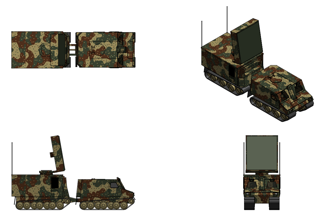
FMG 360 Weapon Locating Radar System
General Characteristics:
Type:Counter-battery radar
Weight:4,500 kg
Platform:Ground vehicle or trailer
Performance Characteristics:
Frequency coverage:5.4 - 5.9 GHz (C band)
Instrumented range:100 km
Azimuth:360° or 120° sector
Elevation:-5° to +85°
Accuracy:<0.25% CEP rocket/howitzer, <0.15% CEP mortar
Target Capability:200 targets/minute
Overview:
The SDI FMG 360 is a C-band active electronically scanned array counter-battery radar system designed by SDI Fire Control Systems. The FMG 360 is intended to provide accurate location of artillery weapons including, howitzer, mortars, and multiple rocket launcher weapons out to a range of 100 kilometers to enable accurate and responsive counter-battery fire. While tracking and locating enemy artillery weapons the FMG 360 can also conduct registration and adjustment of friendly fire missions to correct friendly artillery battery’s counter-fire missions. The complete FMG 360 system consists of a Kfz 310B carrier vehicle and a radar module unit containing the radar antenna and power unit systems.
Carrier Vehicle
The FMG 360 is designed to be carried using a modified Kfz 310B logistic carrier vehicle which acts as the prime mover for the radar system. The radar power unit and antenna system are contained in a container with ISO standard dimensions, allowing the system to be integrated into other tracked or wheeled vehicles capable of carrying ISO standard containers. The radar system has a crew of three including a driver, radar operator, and commander placed in the front cabin of the Kfz 310B carrier.
Radar
The FMG 360 radar antenna consists of a C band (5.4 - 5.9 GHz) active electronically scanned array antenna mounted on rotating platform on top of the radar module container which can be rotated 360° in azimuth and elevated from -5° to +35° relative to vertical. The fully digital array is populated with C-band GaN-on-diamond transmit/receive modules with module level digital receiver/exciter (DREX) modules and a common digital beamformer. On transmit, waveforms are synthesized digitally per subarray while on receive each subarray's signal is digitized close to the aperture and all beamforming is performed in the back end. The back end can simultaneously form large numbers of independent beams, enabling the radar can stare over a wide volume and track hundreds of objects at once. For ECCM performance the antenna supports full adaptive digital nulling with spatial nulls that can be steered onto jammers and strong clutter sources per beam, improving performance in contested electromagnetic environments and against ARM carrying platforms. ECCM features of the radar include the lack of a main lobe, ultra-low sides lobes, pulse to pulse, burst to burst, and scan to scan frequency agility, PRF switching and PRF stagger, and very low peak power. The radar is also equipped with a decoy system consisting of three small digital RF memory (DRFM) transmitters connected using fiber optic cables to the radar which upon queue from the radar system transmit a signal that mimics the radar's sidelobe emissions. The digital waveform generation further supports a very wide bandwidths for fine range resolution, improving weapon locating accuracy and target discrimination capability. With power, exciter and receiver distributed across many modules loss of individual modules degrades performance gracefully rather than catastrophically.
The antenna itself can be electronically scanned +/- 60º in both azimuth and elevation which gives the radar an azimuth sector coverage capability of 120° without having to rotate the antenna. The radar has the ability to scan below the horizon and is designed with the the ability to detect and track projectiles against mountain, forest, and urban backgrounds when used in an overwatch position atop a hill. The radar has three pre-set instrumented range modes; short instrumented range mode with a range of 30 km, standard instrumented range mode with a range of 60 km, and long instrumented range mode with a range of 100 km. All three modes can be interleaved together in a single sector search and the maximum computational range of the radar system is 100 km. In standard instrumented range mode the radar is capable of locating artillery and multiple rocket launcher weapons to within a CEP of 150 meters at a range of 60 kilometers. The radar supports instantaneous 3D tracking and trajectory calculation of projectiles along with projectile caliber discrimination based on extraction of relative drag coefficient. Target location capability is 200 targets per minute with a storage capacity of 20,000 targets.
The radar antenna is coupled to a 6-axis inertial navigation unit which provides the X, Y, and Z radar antenna position and antenna orientation, provides automatic antenna mechanical positioning and compensation, and with data from the carrier vehicle's vehicle motion sensor (VMS) adjusts for terrain slopes and unexpected vehicle movements. The radar is designed to automatically adjust the elevation of its scan pattern to the terrain mask of the local terrain. The adjustment is made using a 3D digital elevation model (DEM) map which is loaded onto the radar with a CD before deployment with the radar's blindspots marked using a viewshed analysis of the digital elevation map. When the radar is initialized for a mission the radar's mission software will display a 200 km2 map with the FMG 360 radar in the center. In the absence of a digital elevation map the radar can perform a scan across its sector to measure the crests of the radar horizon and detect any blind sectors which will then be displayed on the radar display map. The entire radar system can be emplaced and brought into action in less than 2 minutes, or less than 15 minutes when a digital elevation map is not available and a manual sector scan is required to set up the radar.
Operating modes
The FM 360 radar can operate in either automatic or manual modes. In automatic mode the radar missions are controlled by an external command post which remotely defines the radar mission parameters and receives the radar results via datalink. In manual mode there is no datalink connection to an external command post and the radar operator manually defines the parameters of the mission. When set to automatic mode the radar will change to manual mode if the datalink fails or if the radar otherwise loses connection to the external command post. In both modes the radar can be set to either normal location rate mode or high location rate mode. Normal location rate mode is the default mode and maximizes battery location and impact point location accuracy. High location rate mode sacrifices some battery location and impact point location accuracy in order to enable a larger number of projectiles to be simultaneously tracked.
When creating a mission for the radar three types of prioritization can be applied including mission type priority (locating of hostile batteries, adjustment and registration of friendly fire), weapon class (ie mortar, howitzer, rocket) priority, and location zone prioritization. By default the radar will prioritize the location of hostile batteries over the adjustment and registration of friendly fire. When prioritizing weapon classes the system prioritizes the three weapon system classes including howitzers, rocket launchers, and mortars with 4 priority levels, the lowest of which will be used to exclude that weapon system class from tracking and battery locating. Location zones can be defined by the radar operators or transmitted from a command post via datalink and can be prioritized either by weapon location zones, which represent areas where hostile weapons are positioned, or prioritized by impact zones, which prioritizes enemy weapons by their ability to fire on certain friendly location zones. One of six priority levels can be assigned to each location zone, the lowest priority being used to exclude that zone from the radar's search sector. Location zones including impact can be either be circular or a sector defines with grid oriented coordinates.
| SDI AG Arcaenian Military Factbook | Task Force Atlas International Freedom Coalition |
by The Technocratic Syndicalists » Thu Jul 16, 2026 11:11 am

FMG 1000
General Characteristics:
Type:Strategic early warning radar
Platform:Fixed site
Performance Characteristics:
Frequency coverage:8.5 - 10.5 GHz (X band, 9.5 GHz center frequency)
Peak power:25 MW (per face)
Average power:8 MW (per face)
Instrumented range:300,000 km
Detection range (0.01 m² RCS RV):10,000 km
Detection range (1 m² RCS Satellite):30,000 km
Beamwidth:0.1°
Instantaneous bandwidth:1 GHz
Azimuth coverage:240°
Elevation:0° to +80°
Target Capability:1,000 targets/minute per face
Overview:
the SDI FMG 1000 is a fixed, land based, solid state, digital phased array radar system designed to search for, acquire, track, and discriminate incoming ballistic missile lethal reentry vehicles (RVs) from decoys, debris, and countermeasures at ranges exceeding 5,000 kilometers. As a secondary mission the FMG 1000 provides comprehensive Space Domain Awareness (SDA) capability, cataloging and tracking resident space objects including active satellites, defunct spacecraft, rocket bodies, and orbital debris fragments down to approximately 2 centimeters in diameter in low Earth orbit. The facility complex comprises three principal structures including the Radar Building housing both array faces, transmit/receive electronics, and signal processing, the Mission Control Facility providing real-time operations, battle management interfaces, and crew support, and a dedicated Nuclear Small Modular Reactor (SMR) Power Plant providing energy independent grid resilient electrical power.
Radar:
The FMG 1000 radar building contains two 18 m × 18 m planar active electronically scanned arrays (AESAs) are mounted on a common hardened structure, each back tilted 20° from the vertical and oriented to cover complementary azimuth sectors. Each radar face can scan ±60° in azimuth and horizon-to-zenith in elevation, giving a combined field of regard of approximately 240° in azimuth with substantial overlap in the boresight transition zone that covers the primary threat corridor with cross face handover and no coverage seam at boresight. The two faces together provide a wide, gap minimized field of regard over the primary threat corridor while retaining the ability to hand off tracks between faces. Behind each face sits the array back structure with liquid-cooling manifolds, DC power distribution, the digital receiver/exciter (DREX) layer, and fiber optic data egress to the Mission Control Facility housed in a separate hardened structure. Each face is an 18.0 m planar aperture containing over 1.6 million gallium-nitride (GaN-on-SiC) monolithic transmit/receive (T/R) modules providing the transmit power amplifier, low-noise amplifier (LNA), transmit/receive switching or circulation, and multi-bit phase/amplitude control. The 1.6 million element face is further decomposed into four sub-arrays, each an identical, interchangeable, independently testable unit. The sub-arrays, are further decomposed into 0.9 m by 0.9 m array panels, line-replaceable units assemblies containing 4,200 radiating elements, 4,200 GaN T/R channels, 70 digital receive channels, a first-stage digital beamforming FPGA, an integrated microchannel cold plate, and local power conditioning. Each array panel is approximately 50 kg and mounts on quick-release blind mate RF, power, coolant, and optical connector and is extracted rearward from a maintenance gallery without breaking the weather seal or the array face. A 20x20 panel grid divided into four 5x5 subarrays produces the final 18.00 m aperture. The radiating elements are dual-polarized stacked-patch radiators on a low-loss hydrocarbon-ceramic laminate, aperture-coupled to the T/R MMIC beneath. Low-CTE composite is used in the primary load path minimizes thermally induced defocus, where aluminum is used it is thermally tied to the coolant loop so its temperature is controlled. A permanent laser/interferometric metrology network measures true panel positions in real time, residual deformation is corrected in the beamformer the array is electronically flat even when it is mechanically not. The entire array face is mounted on a massive reinforced concrete and structural steel pedestal structure angled at a fixed elevation tilt optimized for the primary threat azimuth and elevation coverage. The structural design is designed to maintain the array face planarity within ±0.5 millimeters RMS across the full 18 by 18 meter aperture under all environmental loading conditions including wind loads up to 200 kilometers per hour (design wind speed), thermal gradients from minus 55° Celsius to plus 50° Celsius ambient, seismic loads corresponding to a 2,500-year return period event, and nuclear blast overpressure loads. The array face backing structure is a welded steel space-frame truss system with nodal connections on a 1 meter grid. The truss depth is approximately 3 meters, providing sufficient stiffness to meet planarity requirements while accommodating cable routing, coolant piping, and maintenance access behind the array. A composite radome panel system covers each array face, providing environmental protection while maintaining electromagnetic transparency with a maximum insertion loss of 0.3 dB and a maximum phase distortion of 5 degrees across the operating bandwidth. The radome panels are designed to withstand ballistic impact from wind-driven debris and ice accretion loads, with integrated de-icing capability via embedded resistive heating elements.
The heart of the RF front end is a gallium nitride (GaN) on silicon carbide (SiC) monolithic microwave integrated circuit (MMIC) high-power amplifier (HPA). GaN-on-SiC technology is selected for its exceptional combination of high breakdown voltage (>100 V), high electron mobility, high thermal conductivity of the SiC substrate, wide bandgap, and inherent radiation hardness. Each T/R module contains a two-stage GaN MMIC HPA producing a peak saturated output power of 16.25 watts per element at 10 GHz with a power-added efficiency of 55%. With approximately 1.6 million modules per face, the total peak radiated power per array face is approximately 25 megawatts and the total mean radiated power is approximately 8.0 megawatts. This enormous radiated power, combined with the 58 dBi antenna gain, produces a single-face peak effective radiated power (ERP) on the order of 100 dBW (10 terawatts ERP), enabling detection and tracking of extremely small radar cross-section targets at extreme ranges. The receive path in each T/R module begins with a GaN-based low-noise amplifier (LNA) providing a noise figure of 1.8 dB and a gain of 28 dB at 10 GHz. The LNA is protected from the transmit pulse by a fast-switching GaN T/R switch with a transition time of less than 50 ns and an isolation of greater than 40 dB, ensuring that the sensitive receiver circuitry is fully protected during high-power transmission. Following the LNA, a variable gain amplifier provides up to 30 dB of dynamic range adjustment, enabling the receive chain to accommodate signals ranging from strong nearby clutter returns to faint signatures from distant small objects. Each T/R module incorporates a direct-digital receiver with a 14-bit analog-to-digital converter (ADC) sampling at 3.2 giga-samples per second (GSPS), providing direct digitization of the X-band signal with a Nyquist bandwidth exceeding the full operational bandwidth. Direct RF digitization eliminates the need for analog downconversion stages, reducing phase noise, spurious signals, and module complexity while enabling fully digital beamforming on receive. The digitized data from each element is transmitted via high-speed serial optical links to the central signal processing system at a raw data rate of approximately 45 gigabits per second per module.
The FMG 1000 employs a fully digital beamforming architecture in which every element's transmit waveform and receive signal are individually controlled and digitized. Unlike subarray-level analog beamforming used in earlier-generation systems, element-level DBF provides the maximum degrees of freedom for beam pattern synthesis, enabling formation of multiple simultaneous receive beams, ultra-low sidelobe patterns with adaptive null placement, and real-time aperture weighting optimization. The system can simultaneously form up to 256 independent receive beams from a single transmitted pulse, enabling concurrent tracking of multiple objects distributed across the field of regard while maintaining search fence operations. The digital beamformer performs real-time complex weighting (amplitude and phase) of all element channels per face at the pulse repetition interval. Adaptive beamforming algorithms including Sample Matrix Inversion (SMI) and eigenspace-based methods are implemented to place deep nulls on jamming sources while preserving gain on threat objects. The system can adaptively suppress up to 64 simultaneous jammers with a null depth exceeding 50 dB, maintaining BMD mission performance in the presence of dedicated electronic attack. The waveform generator produces a library of radar waveforms optimized for the various operational modes. Long range search modes employ lon -pulse linear frequency modulated (LFM) chirp waveforms with pulse widths up to 1 millisecond and bandwidths of 200 MHz, providing unambiguous range coverage to 10,000 kilometers with a compressed range resolution of approximately 0.75 meters. Precision discrimination modes utilize stepped frequency waveforms spanning the full 1.5 GHz operational bandwidth, achieving a range resolution of approximately 0.1 meters sufficient to resolve individual features on a threat complex for signature based discrimination. Space domain awareness modes employ high-PRF medium-bandwidth waveforms optimized for detecting small, fast-moving objects in orbital trajectories. All waveforms are generated digitally and distributed to each T/R module as complex baseband samples via the digital waveform distribution network. The waveform generator supports fully coherent operation across all elements with a phase coherence of better than 2° RMS across the aperture, enabling coherent integration times exceeding 10 seconds for space surveillance targets.
The FMG 1000 signal processing system is a massively parallel computing architecture designed to handle the data throughput generated by element-level digitization of 1.6 million channels per face. The first stage of signal processing is the real-time digital beamformer, implemented on a custom array of field-programmable gate arrays (FPGAs) and application-specific integrated circuits (ASICs) which reduces the data rate by a factor of approximately 400 through spatial filtering (beamforming). The beamformed data representing up to 256 simultaneous beams then flows to the general-purpose signal processing cluster. The signal processing cluster consists of approximately 5,000 high-performance GPU-accelerated compute nodes implementing pulse compression, Doppler filtering, constant false alarm rate (CFAR) detection, monopulse angle estimation, and waveform-adaptive matched filtering. The cluster delivers a sustained computational throughput of approximately 50 exaFLOPS (50 × 10^18 floating-point operations per second), ensuring that all detection, tracking, and discrimination processing occurs within the radar timeline without queuing delays. The system architecture employs a combination of InfiniBand HDR interconnects and custom low-latency optical switching to achieve an end-to-end processing latency from element digitization to track update output of less than 50 milliseconds. The tracking subsystem implements a multi-hypothesis tracker (MHT) capable of maintaining confirmed tracks on at least 1,000 simultaneous objects. The tracker ingests detection reports from all active beams and modes, performs track-to-detection association using probabilistic data association filters, and maintains kinematic state estimates using an interacting multiple model (IMM) estimator that accounts for powered flight, ballistic, and maneuvering motion models. Track state vectors include position, velocity, acceleration, and ballistic coefficient estimates with covariance, enabling high-fidelity trajectory prediction for fire control solutions. Track data is transmitted in Integrated Broadcast Service (IBS) message formats at update rates of up to 10 Hz for priority tracks. The system also supports receipt of external cueing data from space-based infrared sensors, other ground-based radars , and BMD ships, enabling sensor-to-sensor track correlation and multi-source data fusion.
Discrimination:
The FMG 1000 is designed to extract a comprehensive set of observables from each tracked object to perform accurate target classification and threat cloud discrimination. These observables include narrowband radar cross-section (RCS) features including mean RCS, RCS statistical distribution, and RCS variation with aspect angle, wideband range profile features including physical length, shape, and scattering center distribution resolved to 0.1 meter resolution, micro-Doppler features including precession, nutation, tumbling, and spin signatures resulting from rigid-body dynamics in the exo-atmospheric environment, polarimetric features including co-pol/cross-pol ratios and polarimetric covariance matrix elements, and kinematic features including ballistic coefficient, drag deceleration (upon atmospheric entry), and trajectory deviations from Keplerian predictions. The radar implements a hybrid discrimination architecture combining physics based models with machine learning classifiers. The physics based component employs high fidelity electromagnetic scattering models, orbital mechanics propagators, and reentry aerodynamics simulations to predict the expected observables for each hypothesized object class (RV, lightweight decoy, heavy decoy, debris, etc.) given the estimated trajectory and orientation state. The machine learning component employs a deep neural network ensemble trained on an extensive database of simulated threat signatures, hardware-in-the-loop test data, and flight test observations. The discrimination decision engine fuses all available observables and classifier outputs using a Bayesian inference framework that produces posterior probability estimates for each object class. The system is designed to provide a probability of correct classification (Pcc) exceeding 95% for the defined threat set under clear channel conditions, and exceeding 85% in the presence of coordinated electronic attack and advanced countermeasures. Discrimination products including object class probabilities and confidence intervals, are reported within the tracking update timeline to enable timely engagement decisions. The discrimination processing subsystem is hosted on a dedicated high performance computing cluster separate from but integrated with the signal processing cluster. This cluster comprises approximately 1,200 GPU-accelerated compute nodes each equipped with 8 data center GPUs optimized for mixed precision tensor operations, providing a combined throughput exceeding 15 exaFLOPS of AI inference performance. The discrimination cluster receives wideband range profiles, micro-Doppler spectra, and polarimetric feature vectors from the signal processing chain and executes the full discrimination pipeline including feature extraction, physics model evaluation, ML inference, and Bayesian fusion within a processing budget of 200 milliseconds per object per update.
Cooling:
The FMG 1000 generates approximately 110 megawatts of waste heat at full operational power, predominantly from the T/R module arrays, power conditioning equipment, and signal processing data center. The cooling system architecture employs module-level cold plate cooling, an intermediate building-level liquid cooling loop, and a sitelevel heat rejection system. Each T/R module LRU is mounted on an aluminum-silicon carbide (AlSiC) cold plate through which a polyalphaolefin (PAO) dielectric coolant flows. The PAO coolant is used for its excellent dielectric properties (eliminating the risk of electrical faults in the densely packed RF electronics), wide operating temperature range (minus 55 to 175° C), and long service life. Each array face requires a PAO coolant flow rate of approximately 17,500 liters per minute to maintain T/R module junction temperatures within limits. The PAO loop exchanges heat with a building level propylene glycol/water loop through plate-and-frame heat exchangers located at the base of each array structure. The signal processing and discrimination computing clusters are cooled by a dedicated liquid cooling system employing direct-to-chip warm water cooling. Each compute node has water blocks on the GPUs and processors, with a facility water supply temperature of 35° C enabling highly efficient heat rejection without mechanical refrigeration for a significant portion of the year at northern latitudes. Rear door heat exchangers on the server racks capture residual air-side heat. The data center cooling system requires a total flow rate of approximately 30,000 liters per minute. The site level heat rejection system dissipates the aggregate thermal load to the atmosphere using a combination of closed circuit cooling towers and dry coolers. During cold weather operations the dry coolers can handle the full thermal load without evaporative water consumption. During warmer periods the cooling towers provide supplemental evaporative cooling. The heat rejection plant comprises twelve large-format cooling towers with a combined heat rejection capacity of 140 megawatts, providing margin above the steady state thermal load. The cooling towers and dry coolers are located in a protected compound adjacent to the radar building with hardened coolant piping routed below ground.
Site Layout:
The FMG 1000 site is organized inte three structures. The Radar Building is centrally located and oriented with its two array faces covering the primary threat azimuths. The Mission Control Facility is positioned approximately 500 meters from the Radar Building, outside the predicted debris footprint from a direct hit on the radar building but within the range of the underground connecting tunnel. The SMR Power Plant is located approximately 800 meters from the Radar Building and 400 meters from the MCF with terrain and earth berming providing additional blast attenuation between the power plant and the other structures. The site includes a heat rejection compound adjacent to the radar building housing cooling towers and dry coolers; a diesel generator facility housing two 5 MW emergency generators and 30 day fuel storage, a maintenance and logistics building providing warehouse storage, heavy equipment maintenance bays, and receiving/shipping dock, a vehicle maintenance garage, a personnel entry control building at the site perimeter; and a helicopter landing pad. Paved roadways connect all facilities, with the primary access road entering through the entry control building and secondary emergency access routes providing alternate egress. The site is enclosed within a double-fenced restricted area with a 100 meter clear zone between the outer perimeter fence and the inner restricted area fence. The perimeter security system includes microwave intrusion detection sensors, infrared cameras with automated video analytics, seismic ground sensors, and lighting sufficient for positive identification at all fence lines. The three principal buildings each have independent access control systems with two-person integrity and biometric authentication.
All three principal structures (radar building, MCF, and SMR power plant) are constructed to survive nuclear blast overpressure substantially exceeding the hardness levels of standard military construction. Blast hardening features include monolithic reinforced concrete exterior walls and roof slabs with minimum thicknesses of 4 feet for the radar building and MCF and 6 feet for the reactor containment structures, employing high strength concrete with a compressive strength of 55 MPa and Grade 75 reinforcing steel with closely spaced ties and seismic detailing. All structures are founded on continuous mat foundations of 6-foot minimum thickness bearing on competent rock. Blast doors at all entry points are rated for the design overpressure and are operable from both manual and automatic actuators. All penetrations through the hardened envelope including cable entries, piping, HVAC ducts, and antenna waveguide ports are protected by blast valves and closures that seal automatically upon detection of a blast wave. The underground utility tunnels connecting the three buildings are reinforced concrete box structures with blast-resistant expansion joints at building interfaces. The radar array face radome is designed as a frangible structure that may sustain damage from blast loading without compromising the structural integrity of the array backing structure; the array is designed to operate with up to 15% of radome panels missing or damaged. A;;l exterior surfaces of the three buildings are clad in high-reflectivity, low-absorptivity thermal barrier coatings with a solar absorptivity of less than 0.15, minimizing thermal energy absorption. The radome panels incorporate a thermal protection layer capable of surviving the design thermal fluence without structural degradation. All exterior exposed cable trays, piping, and equipment are either enclosed within the hardened envelope or protected by thermal shields. Interior fire protection includes a site-wide automatic fire detection and suppression system employing Halon suppression in electronics spaces and radar equipment bays, pre-action sprinkler systems in administrative and support spaces, and foam suppression in generator and fuel storage areas. Passive fire protection includes fire-rated barriers between all major functional areas with a minimum fire resistance rating of 2 hours. All interior furnishings and materials meet stringent flame-spread and smoke-generation requirements. The SMR plant fire protection incorporates additional provisions for nuclear grade safe shutdown capability.
The complex is further hardened against electromagnetic pulse (EMP) effects from both high-altitude nuclear detonations (HEMP) and source-region EMP (SREMP). The primary EMP protection is a continuous welded-steel electromagnetic Faraday cage enclosing each of the three buildings. The shield provides a minimum shielding effectiveness of 80 dB from 10 kHz to 1 GHz. All electrical and signal conductors penetrating the shield boundary are protected by EMP-rated transient voltage surge suppressors (TVSS). Fiber optic cables are used for all inter-building communications to eliminate conducted EMP coupling between structures. EMP protection for the array is achieved through a combination of frequency-selective surface (FSS) sub-layers in the radome that are transparent at X-band but reflective at EMP frequencies (below 1 GHz), EMP limiter diodes integrated into each T/R module at the antenna port, and fast-acting waveguide switches that can isolate the T/R modules from the antenna elements within 20 nanoseconds of EMP detection. Dedicated EMP sensors located on the building exterior trigger the protective sequence. All mission-critical electronic systems are hardened against transient radiation effects on electronics (TREE) produced by the prompt gamma and neutron radiation from a nuclear detonation. The GaN-on-SiC T/R module technology provides inherent radiation hardness due to the wide bandgap (3.4 eV) and strong atomic bonding of the GaN crystal, with total ionizing dose (TID) tolerance exceeding 1 megarad(Si) and negligible neutron displacement damage effects at operationally relevant fluences. The signal processing and mission computing systems employ radiation-hardened-by-design (RHBD) processors and memories with TID tolerance exceeding 300 kilorad(Si) and single-event upset (SEU) immunity achieved through triple modular redundancy (TMR) and error-correcting code (ECC) memory. The reactor instrumentation and control systems are qualified to nuclear-grade radiation hardness standards and are further hardened against the external nuclear weapon radiation environment. Power distribution electronics employ silicon carbide (SiC) semiconductor devices that share GaN's wide bandgap radiation tolerance advantages.
| SDI AG Arcaenian Military Factbook | Task Force Atlas International Freedom Coalition |
Return to Global Economics and Trade
Users browsing this forum: No registered users