NATION

PASSWORD

SDI Space Systems Catalog [DO NOT POST]

A meeting place where national storefronts can tout their wares and discuss trade. [In character]
User avatar
The Technocratic Syndicalists
Minister
 
Posts: 2349
Founded: May 27, 2015
Inoffensive Centrist Democracy

SDI Space Systems Catalog [DO NOT POST]

Postby The Technocratic Syndicalists » Sat May 20, 2017 7:29 pm

Image

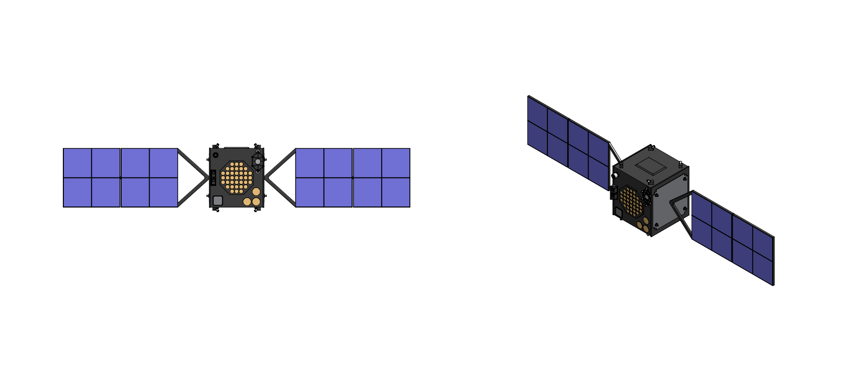
MicroEye

General Characteristics:
  • Function: Multispectral Imaging Satellite
  • Dimensions: 3.6 m x 0.5 m x 1.1 m
  • Launch Mass: 100 kg
  • Electrical Power: 250 W
  • Attitude Control: 3-axis momentum biased
  • Propulsion: 4x gold gas thrusters
  • Telemetry: S Band
Instruments:
  • Multispectral Imager (0.35 m telescope 0.75 m resolution, 8 spectral bands)
    • Band 1 Coastal Blue (0.40 - 0.45 µm)
    • Band 2 Blue (0.45 - 0.51 µm)
    • Band 3 Green (0.51 - 0.58 µm)
    • Band 4 Yellow (0.58 - 0.62 µm)
    • Band 5 Red (0.63 - 0.69 µm)
    • Band 6 Red edge (0.71 - 0.74 µm)
    • Band 7 Near-IR 1 (0.77 - 0.89 µm)
    • Band 8 Near-IR 2 (0.86 - 1.04 µm)
Orbital parameters:
  • Orbit height: 500 km
  • Orbit inclination: 51.64o
  • Design life: 2 years


Overview:
MicroEye is an electro-optical imaging microsatellite manufactured by SDI Space Systems which is designed to be capable of providing on-demand multispectral imagery with a tactically useful resolution which it can then downlink directly to military commanders and intelligence centers in the same pass (<10 minutes within being tasked) without the use of a satellite or ground based relay network.


Instruments:
Multispectral Imager: The primary instrument of the MicroEye is a 35 centimeter optical telescope mounted to the spacecraft with three three aft hard-points which is mated with an SDI deigned 40,000 pixel TDI line scan Silicon CCD camera which is capable of imaging in panchromatic (Pan) mode in the 0.45 - 0.80 µm spectral range or in multispectral (MS) mode with 8 spectral bands. From an altitude of 500 kilometres the satellite's multispectral imager can image a 5.8 x 3.8 km area with a ground resolution of 0.75 - 1.0 meters. Images from the camera are compressed into an NITF format where they can be stored on the spacecraft (up to 600 images) and/or transmitted in real time to a ground station for exploitation.


Spacecraft:
Satellite Bus:The Microeye uses a proprietary SDI designed satellite bus which measures 0.5 m x 0.5 x 1.1 m before solar panel deployment with a launch mass of 100 kilograms including the multispectral imager payload. Electrical power is provided by five deployable solar panels which combined provide up to 250 watts of electrical power to the satellite's electrical power subsystem (EPS). The electrical power subsystem also includes a 16 cell Lithium Ion (Li-Ion) battery made from four 4-Cell commercial laptop batteries which have been wired together.

Attitude Control & Propulsion: The spacecraft's Attitude Determination And Control Subsystem (ADACS) consists of a single star tracker, eight coarse sun sensors placed around the spacecraft body, a 9-axis inertial measurement unit (IMU) including 3-axis MEMS gyros and a 3-axis magnetometer, a GPS receiver, and an attitude control system consisting of three reaction wheels and three magnetic torque rods which can slew the satellite at a rate of up to 3°/s to off-nadir imaging angle of up to 30 degrees° with a pointing accuracy of less than 0.15°. Spacecraft propulsion is via a cold-gas propulsion subsystem which contains two composite-overwrapped pressure vessels storing compressed nitrogen gas, twin pressure regulators, a magnetic latch valve, and four outward-canted gold gas thrusters mounted at the rear corners of the spacecraft which provide 3-axis propulsion and torque control.

Communications: The spacecraft's communications system consists of two S-band (2200.5 MHz – 2394.5 MHz) quadrifilar helix antennas (QHAs) on the nadir end of the spacecraft (one transmit and one receive) and two S-band patch antennas on the zenith end of the spacecraft (also one transmit and one receive) which are used for 2-way communications with ground stations at any satellite attitude. Transmitted data is modulated using offset quadrature phase shift keying (OQPSK) modulation with a maximum data downlink rate of over > 1 Mbps.


Ground Control:
To use the satellite a ground commander first determines the GPS grid coordinates of an area he wished to image (up to 5.8 x 3.8 km) which he then relays using a tactical command post with satellite uplink capability. At each command post requests for imagery from different commanders are and merged and prioritized with imagery requests from other commanders in the same theater where they are then relayed to the nearest MicroEye satlelite as it rises over the theater area. The command software on the satellite processes the received imaging requests and then actuates the satellite using its attitude control system to capture imagery of the target areas with an optimized set of attitude slews, snapping imagery of each target area before rapidly slewing to the next target. Images taken are streamed in real time back to tactical command posts on the ground which then transmits the data back to the requesting commander, the entire process from image request to receiving imagery taking less than 10 minutes.
Last edited by The Technocratic Syndicalists on Mon Feb 22, 2021 2:22 pm, edited 15 times in total.
SDI AG
Arcaenian Military Factbook
Task Force Atlas
International Freedom Coalition


OOC: Call me Techno for Short
IC: The Kingdom of Arcaenia

User avatar
The Technocratic Syndicalists
Minister
 
Posts: 2349
Founded: May 27, 2015
Inoffensive Centrist Democracy

Postby The Technocratic Syndicalists » Thu May 25, 2017 10:18 pm

Image

STARSCAN

General Characteristics:
  • Function: Space Based Radar Satellite
  • Dimensions: 24.5 m x 2.5 m x 4.3 m
  • Launch Mass: 3,400 kg
  • Electrical Power: 28.0 kW
  • Attitude Control: 3-axis momentum biased
  • Propulsion: 4x monopropellant hydrazine thrusters, 25 N each
  • Telemetry: S/Ka Band
Instruments:
  • Electronically Scanned Radar
Orbital parameters:
  • Orbit height: 700 km
  • Orbit inclination: 55 o
  • Design life: 20 years


Overview:
Starscan is a space based radar system designed by SDI Space Systems which is designed to provide Air Moving Target Indication (AMTI), Ground Moving Target Indication (GMTI), Maritime Moving Target Indication (MMTI), Synthetic Aperture Radar (SAR) mapping, and Inverse SAR (ISAR) imaging with integrated battle management functions. Starscan is designed to provide continuous wide-area air surveillance for detection and tracking of manned aircraft, unmanned aerial vehicles (UAVs), cruise missiles, hypersonic glide vehicles, and ballistic missile re-entry vehicles with the ability to generate real-time recognized air picture (RAP) data for integration into theater and national air defense network, deliver persistent GMTI and SAR coverage over areas of interest to detect, locate, and track ground vehicles, troop movements, mobile missile launchers, and logistics activity to support targeting, battle damage assessment, and ground force maneuver planning, detect, classify, and track surface vessels across contested maritime zones and open ocean. The system delivers Air Moving Target Indication with HRR profiling (AMTI-HRR), Ground Moving Target Indication with HRR (GMTI-HRR), Maritime Moving Target Indication with HRR (MMTI-HRR), Synthetic Aperture Radar (SAR) mapping, Inverse SAR (ISAR) imaging, interleaved SAR/HRR-GMTI modes, ballistic missile tracking and discrimination, and integrated battle management functions with global persistence. The architecture incorporates comprehensive counter-ASAT countermeasures and physical, electronic, and cyber hardening to operate in contested space environments.

The Starscan constellation employs a modified Walker Delta pattern optimized for mid-latitude coverage density while maintaining polar observation capability. The architecture distributes 48 radar satellites across six orbital planes inclined at 55°, with eight satellites per plane evenly spaced in true anomaly. The constellation design ensures that at any given moment a minimum of three satellites have overlapping coverage of any point between 60°N and 60°S, with at least one satellite available up to 75° latitude. Orbital altitude is set at 700 km as a baseline the orbital period is approximately 100 minutes, providing rapid ground-track progression and short revisit intervals.


Instruments:
Electronically Scanned Radar:Each Starscan satellite is fitted with an X-band (10.0 GHz center frequency, 2 GHz bandwidth) active electronically scanned array (AESA) radar with a 16.0 x 2.5 m antenna. The antenna is constructed from lightweight composite honeycomb panels with integrated gallium nitride (GaN) transmit/receive (T/R) modules. The antenna deploys from a stowed configuration of approximately 2.5 m x 3 m using an accordion-fold mechanism with shape-memory alloy hinges and motor-driven deployment rails. The array contains approximately 90,000 radiating elements fed by a total of 12,000 dual-polarized GaN (gallium nitride)-on-diamond T/R modules. The array supports full digital beamforming at the sub-array level with 64 digital receiver channels and 16 digital transmit channels, enabling multiple simultaneous receive beams, wideband digital pulse compression, and advanced space-time adaptive processing. The radar is capable of steering electronically +/- 45°in elevation (perpendicular to the ground track) and +/- 45° in azimuth (parallel to the ground track) and can also use its attitude determination & control system (ADCS) to roll up to 30° for enhanced coverage on either side of the satellite's ground track. Antenna polarization options are varied based on the combination of operation modes selected and include single (HH or VV or HV or VH), dual (HH and VV, VV and VH, or HH and VV), and quad (HH+VV+HV+VH) polarization. The Starscan radar employs a sophisticated multi-mode waveform generator capable of producing linear FM chirp, stepped-frequency, phase-coded, and hybrid waveforms with pulse-to-pulse frequency agility. Instantaneous bandwidth ranges from 10 MHz (for wide-area AMTI search) to 1.2 GHz (high-resolution HRR profiling and spotlight SAR) corresponding to range resolutions from 15 m down to 0.125 m. Pulse repetition frequencies (PRFs) are software-selectable across the range of 500 Hz to 200 kHz, supporting both low-PRF unambiguous range modes for long-range search and high-PRF unambiguous Doppler modes for velocity measurement. On-board signal processing is executed by a radiation-hardened high-performance computing payload comprising multiple field-programmable gate arrays and graphics processing units delivering approximately 80 TFLOPS of sustained throughput. Key processing functions include wideband digital pulse compression with sidelobe weighting for HRR profile generation across all MTI modes, space-time adaptive processing (STAP) for clutter suppression in AMTI and GMTI modes, exploiting the full 64-channel digital architecture, along-track interferometric (ATI) and displaced phase center antenna (DPCA) processing for enhanced slow-mover detection and platform-motion compensation in GMTI, HRR profile extraction, normalization, and feature-vector generation for automatic target classification in AMTI-HRR, GMTI-HRR, and MMTI-HRR modes, interleaved timeline management for simultaneous SAR imaging and HRR-GMTI surveillance within the same antenna beam footprint, BMD-specific midcourse tracking with extended Kalman filter, HRR-based object length estimation, and micro-Doppler analysis for warhead-decoy discrimination, Coherent change detection (CCD) between successive SAR passes for activity monitoring, Autofocus algorithms (phase gradient autofocus, map-drift) for SAR image formation, CFAR detection with adaptive thresholding and track-before-detect for sub-threshold targets, and on-board deep neural network inference engines for automatic target recognition (ATR), trained on HRR signature libraries and SAR image databases

The base operating modes of Starscan include AMTI-HRR, GMTI-HRR, MMTI-HRR, Interleaved SAR/HRR-MTI, Strimpap SAR, Spotlight SAR, ScanSAR, and ISAR. The system also supports a ballistic missile defense (BMD) mode with three BMD sub-modes, space surveillance mode, Electronic Support Measures (ESM) / Electronic Intelligence (ELINT) modes, and weather observation modes. The AMTI-HRR mode replicates and extends airborne AEW capability by performing wide-area air surveillance from orbit with embedded high range resolution target profiling. The electronically steered beam sequences through azimuth sectors while maintaining pulse-Doppler processing for target detection against ground and sea clutter backgrounds. Upon initial detection, the radar automatically schedules HRR dwells on each tracked target using wideband waveforms (500 MHz–1.2 GHz bandwidth), generating range profiles with resolution of 0.15–0.30 m that resolve individual scattering centers on the target airframe. HRR profiles are processed on-board to extract feature vectors including target length, scatterer distribution, symmetry, and spectral characteristics, which are compared against a stored signature library using neural-network classifiers. This enables non-cooperative target recognition (NCTR) of aircraft type (fighter, bomber, transport, tanker, UAV, rotary-wing, cruise missile) with classification accuracies exceeding 90% for known types. The HRR dwell is interleaved with surveillance scan at the waveform timeline level: each beam position alternates between a short-bandwidth search pulse and a wideband HRR pulse on a pulse-to-pulse basis, maintaining continuous surveillance coverage while building HRR profiles on detected targets. STAP algorithms leverage the large antenna aperture and 64 digital channels to achieve mainbeam clutter cancellation ratios exceeding 55 dB, enabling detection of targets with RCS as low as 0.01 m² at operationally useful ranges. The system can simultaneously maintain a wide-area surveillance fence while prosecuting track-while-scan with HRR on up to 3,000 air targets, with track update rates of 2–4 seconds for priority targets

GMTI-HRR mode provides wide-area ground surveillance capability augmented with high range resolution profiling for vehicle classification. The radar illuminates designated ground sectors with optimized waveforms while applying STAP and DPCA techniques to suppress ground clutter. Upon detection of moving targets, the system automatically schedules HRR dwells that generate range profiles resolving individual vehicle scattering features at 0.15–0.30 m resolution.HRR profiles of ground movers enable discrimination between vehicle classes: main battle tanks, armored personnel carriers, self-propelled artillery, trucks, light vehicles, and mobile missile launchers such as transporter-erector-launchers (TELs).The system processes HRR returns through on-board classifiers trained on measured vehicle signature databases, reporting target class with confidence scores alongside position, velocity, and heading. At the baseline altitude ofn700 km with the 16 m antenna, the minimum detectable velocity is approximately 0.5–1.0 m/s after STAP processing. Wide-area search mode covers a swath of up to 200 km and scans at rates exceeding 200,000 km²/hr. Sector search mode concentrates radar energy on smaller areas of interest with increased dwell time, improving sensitivity for slow-moving targets. Geolocation accuracy is better than 50 m CEP for all detected movers. MMTI-HRR mode extends detection to the maritime domain with integrated high range resolution vessel profiling. Sea clutter suppression is enhanced by dual-polarization processing and spectral analysis of the sea clutter Doppler signature. Large vessels (RCS > 1,000 m²) are detectable at extreme ranges, while small craft (RCS > 1 m²) are detectable beyond 500 km from the sub-satellite point. Upon detection, wideband HRR dwells produce range profiles that resolve a ship’s length, superstructure layout, and mast positions, enabling hull-type classification (aircraft carrier, cruiser, destroyer, frigate, cargo vessel, tanker, fishing boat, fast attack craft) without requiring ISAR imaging. For stationary or slow-moving vessels where HRR alone is insufficient, ISAR imaging exploiting the target’s rotational motion provides two-dimensional imagery at sub-meter resolution for detailed identification. The combination of HRR for initial classification and ISAR for refinement provides a tiered identification pipeline that optimizes radar resource utilization.

The interleaved SAR/HRR mode enables simultaneous high-resolution terrain mapping and moving-target surveillance within the same collection pass. This mode exploits the agility of the AESA and waveform generator to rapidly switch between SAR and GMTI functions on a pulse-group basis, producing both a SAR image and a GMTI mover overlay from a single satellite pass over the area of interest. The interleaving operates on a timeline-division basis. The radar transmits a burst of coherent SAR pulses (typically 50–200 pulses at high PRF with full 1.2 GHz bandwidth) to form one azimuth segment of the SAR image, then immediately switches to a GMTI waveform (lower bandwidth, optimized PRF for clutter cancellation) for a dwell period sufficient to detect and profile movers using HRR within the SAR scene. This cycle repeats at rates of 5–20 Hz, interleaving SAR and GMTI functions with minimal impact on either mode’s performance. The resulting product is a high-resolution SAR image (0.5–1.0 m resolution in stripmap, 0.15–0.30 m in spotlight) with superimposed GMTI detections showing moving target positions, velocities, headings, and HRR-derived classifications. This fused product is invaluable for operations such as monitoring road network, assessing airfield operations where parked aircraft (SAR) and taxiing aircraft (GMTI-HRR) must be observed simultaneously, and surveilling port facilities where docked vessels (SAR) and underway vessels (MMTI-HRR) require concurrent tracking. The interleaved mode timeline is managed by the on-board resource scheduler, which dynamically adjusts the SAR-to-GMTI duty cycle ratio from 90/10 (mapping priority) to 30/70 (mover priority) based on mission tasking, detected activity levels, and operator commands. Adaptive algorithms automatically increase GMTI dwell time when high mover density is detected in the scene, ensuring that HRR profiles are collected on all targets of interest. Stripmap SAR mode provides continuous imaging along the ground track with resolution of 1.0 t 3.0 m over swath widths of 20–40 km. In Spotlight SAR mode the beam is steered to dwell on a fixed ground patch, achieving 0.3 m resolution over scene sizes of 5 km x 5 km. ScanSAR provides wide-swath imaging (100–300 km) at reduced resolution (5–15 m) for broad-area surveillance and change detection. All SAR modes support full polarimetric operation (HH, HV, VH, VV) for enhanced target discrimination and terrain classification, with coherent change detection between revisit passes used to enable detection of disturbed earth, new construction, and vehicle tracks.

The Ballistic Missile Defense (BMD) mode of the radar provides precision tracking and discrimination of ballistic missile objects from the late-boost phase through the midcourse phase of flight. Operating in X-band with the full 1.2 GHz waveform bandwidth, the radar generates HRR profiles of exo-atmospheric objects with range resolution of 0.125 m, resolving individual components of the threat cloud, re-entry vehicle (RV), post-boost vehicle (PBV), decoys, chaff, debris, and tank fragments. The BMD mode operates in three sub-modes including cued search, precision track, and discrimination. In cued search mode upon receiving a launch notification from a apace-based infrared early warning sensor the radar slews to the predicted threat corridor and conducts a search fence using a medium-bandwidth waveform. The look-up geometry from LEO provides favorable detection conditions against midcourse objects above the atmosphere, with no ground clutter and minimal atmospheric attenuation. Detection ranges exceed 2,000 km slant range against objects with RCS > 0.01 m². Once midcourse objects are detected, the radar transitions to a high-update-rate track mode using narrow beams and wideband waveforms. The 0.08° azimuth beamwidth at X-band provides angular measurement accuracy of approximately 0.005° (3σ), translating to cross-range position accuracy of approximately 50 m at 600 km range. Range accuracy from the wideband waveform is approximately 0.1 m. Track state vectors are generated at update rates of 5–10 Hz per object and formatted for direct injection into the BMDS C2BMC system. For threat object discrimination the wideband HRR profiles collected during precision track are processed through discrimination algorithms that exploit multiple physical observables: object length (RVs are typically shorter than decoys), scintillation characteristics (rigid bodies vs. inflatable decoys), precession signatures (spin-stabilized RVs exhibit periodic RCS modulation), micro-Doppler from tumbling or vibrating structures, and polarimetric signatures. A multi-hypothesis discrimination processor assigns lethal-object probability scores to each tracked object, enabling the fire-control system to prioritize interceptor allocation.

Additional radar modes include Inverse SAR (ISAR) providing high-resolution imaging of moving targets (aircraft, ships) using target motion for cross-range resolution to support non-cooperative target recognition (NCTR), space Surveillance mode for detection and tracking of objects in LEO and MEO using upward-looking beam positions to supports space domain awareness (SDA) as a secondary mission, electronic Support Measures (ESM) / Electronic Intelligence (ELINT) using passive receive mode for detection, geolocation, and characterization of hostile radar and communications emitters using the large antenna aperture as a high-gain receiving array, weather observation mode with dual-polarization precipitation measurement capability as a tertiary mode, providing operational weather data over data-sparse oceanic and polar regions, and coherent Multi-Static Operation mode where two or more satellites illuminate the same scene from different angles simultaneously, enabling bistatic/multistatic SAR for enhanced target detection and low-RCS target illumination at geometrically favorable bistatic detection angles.

For radar sensor and mission processing each Starscan satellite carries a dual-redundant radiation-hardened processing payload comprising an FPGA-based real-time signal processor and a GPU-based applications processor. The FPGA layer (four Xilinx Versal AI Edge devices, rad-hard by design) handles time-critical functions including digital beamforming, wideband pulse compression for HRR, STAP, DPCA, and CFAR detection at wire-speed, delivering over 80 TFLOPS sustained. The GPU layer (dua rad-hard inference accelerators) performs higher-level functions including HRR feature extraction, ATR classification, SAR image formation, BMD discrimination processing, and resource scheduling. The ATR system uses deep convolutional neural networks trained on extensive HRR signature and SAR image databases to classify detected targets into operational categories. For AMTI-HRR, the classifier distinguishes among 25+ aircraft types, cruise missile variants, and UAV classes. For GMTI-HRR, the classifier identifies 30+ ground vehicle types with emphasis on high-value targets (TELs, air defense systems, command vehicles). For BMD, a dedicated discrimination neural network processes HRR profiles, micro-Doppler features, and polarimetric observables to score lethal-object probability. All models are updateable via secure ground command, enabling adaptation to new threats within hours of model retraining. The on-board autonomy system manages radar resource scheduling using a constraint-based optimization algorithm that allocates beam time across concurrent requirements—surveillance search, HRR track update, SAR tasking, BMD cueing, interleaved SAR/GMTI operations, electronic support—while respecting power, thermal, and data-rate constraints. The scheduler responds autonomously to BMD cues within 2 seconds, pre-empting lower-priority modes and configuring the radar for BMD tracking without ground-in-the-loop delay.


Spacecraft:
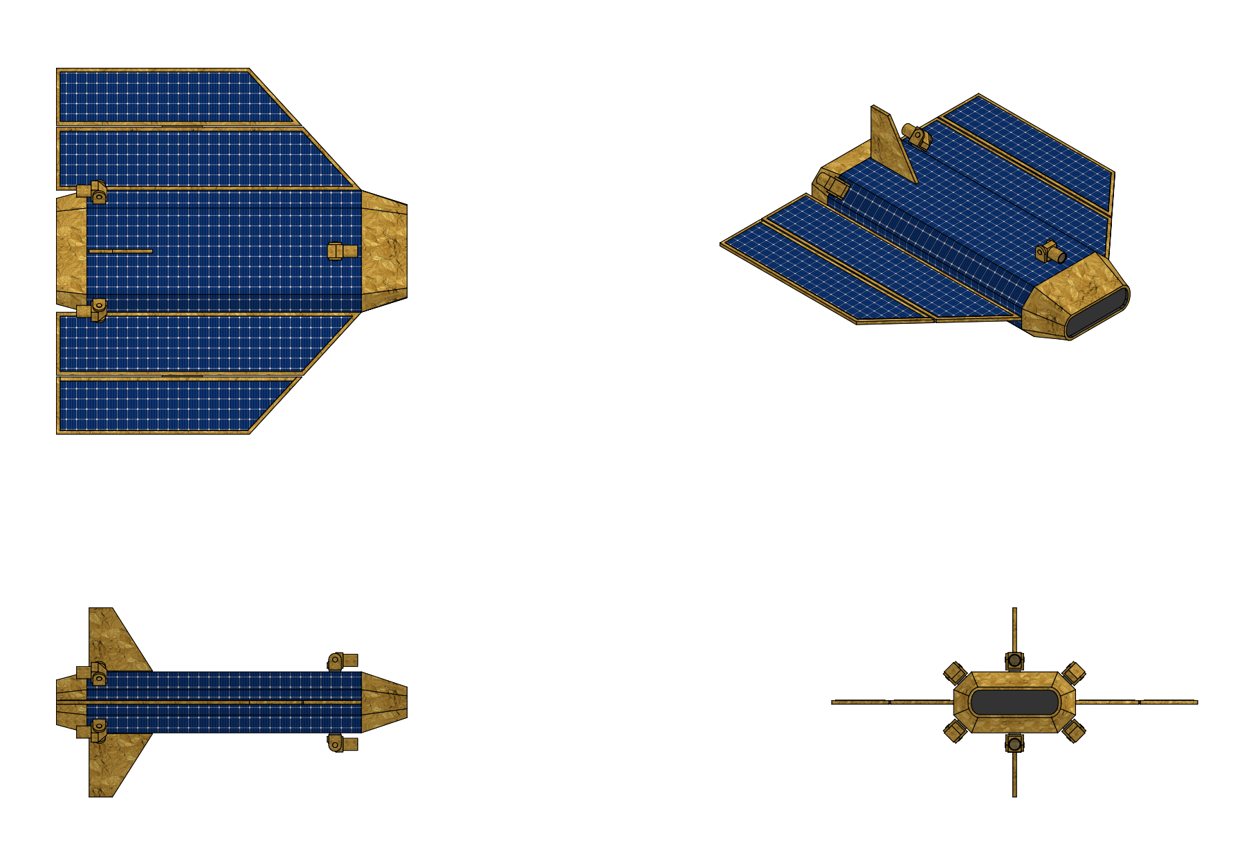
Satellite Bus:The STARSCAN uses an SDI Space Systems RadarSat satellite bus which is designed by SDI for use with both large commercial and military radar payloads. The RadarSat spacecraft bus itself is a high-power, high-stability platform designed to provide precise attitude control for antenna pointing, high electrical power for radar transmission, and substantial thermal management capacity for the active array. The bus employs a box-truss primary structure manufactured from carbon-fiber-reinforced polymer (CFRP) composite, providing high stiffness-to-mass ratio and dimensional stability across the thermal extremes of LEO. The structure is designed to accommodate the stowed antenna assembly along one face (the Earth-facing panel) and the twin solar array wings on the opposing anti-Earth panel, with propulsion modules at the aft bulkhead and avionics within a central equipment bay. The bus is designed around a modular avionics architecture using a SpaceVPX backplane for high-speed inter-module communication. All critical subsystems are dual-redundant with cross-strapped power and data buses. The electrical power subsystem (EPS) is designed to deliver sustained high power for continuous radar operations including BMD tracking modes that demand prolonged high-duty-cycle transmission. Dual deployable solar array wings use quadruple-junction inverted metamorphic (IMM) gallium arsenide cells with beginning-of-life efficiency of 33% and end-of-life efficiency of approximately 29% after 15 years of radiation degradation and thermal cycling. Each wing provides approximately 44 m² of active cell area on a lightweight roll-out solar array (ROSA) structure, generating a combined 28 kW at end of life. Power conditioning and distribution is managed by a fully regulated 100 V main bus with distributed point-of-load converters for each subsystem. A sequential shunt regulator handles excess power during low-load conditions. The battery system comprises four lithium-ion battery packs with a total capacity of 12 kWh, providing full eclipse power (approximately 36 minutes per orbit at 700 km) while maintaining state-of-charge above 30% to preserve cycle life over the 15-year mission. Peak radar load during high-duty-cycle BMD tracking is approximately 22 kW; the battery system supplements solar array output during transient overloads.

The thermal control subsystem (TCS) employs a multi-tier architecture combining passive and active elements to maintain all components within their qualified temperature ranges across all orbital and operational conditions. The primary thermal path routes waste heat from the radar T/R module baseplates through aluminum-ammonia constant-conductance heat pipes (CCHPs) embedded in the antenna panel substrate to the rear face of the antenna, which serves as the primary radiator with an effective area of approximately 40 m². The radiator surface uses high-emissivity silver-Teflon optical solar reflectors (OSRs) to maximize infrared emission while minimizing solar absorption. For peak thermal loads exceeding passive capacity, two deployable supplementary radiator panels (3 m² each) extend from the bus anti-sun side. Active thermal control employs four mechanically pumped fluid loops (MPFL) using single-phase propylene glycol-water coolant, circulating fluid through cold plates on the highest-power components (power amplifiers, digital processors, power conditioning units). The MPFLs reject heat to dedicated radiator zones with diode heat pipes that prevent reverse heat flow during eclipse or cold-case conditions. Phase-change material (PCM) thermal capacitors (paraffin-based, 5 kg each) at critical locations buffer transient thermal spikes during mode transitions from low-power surveillance to high-power BMD tracking. Supplementary deployable radiators on the bus anti-sun side provide an additional 6 m² of rejection area. The system is designed to maintain T/R module junction temperatures below 150°C across all orbital and operational conditions, ensuring long-term reliability.

Attitude Control & Propulsion: The RadarSat bus Attitude Determination and Control Subsystem (ADCS) employs four single-gimbal control moment gyroscopes (SGCMGs) provide high-torque capability for rapid slewing (up to 3°/s body rate for BMD cue response), while six miniature reaction wheels in a skewed-redundant configuration provide fine-pointing control and momentum trimming. CMG angular momentum storage is 75 N·m·s per unit, sufficient for agile retargeting between surface surveillance and BMD look-up modes. Attitude determination uses a multi-sensor fusion architecture with two star tracker head providing absolute attitude reference with accuracy of 1 arcsecond (1σ) per axis. A mHRG (milli-Hemispherical Resonator Gyro) inertial measurement unit with bias stability of 0.0005°/hr provides high-bandwidth angular rate measurements for propagation between star tracker updates and during slew maneuvers. Dual-frequency GPS receivers (L1/L2) with integrated carrier-phase navigation provide position knowledge to 0.1 m (3σ) and velocity knowledge to 0.01 m/s. An Earth nadir sensor also provides coarse attitude backup. The satellite supports three distinct pointing modes: Earth-pointing for surface surveillance, inertial-pointing for BMD tracking of exo-atmospheric objects, and slew-to-cue for rapid retargeting at rates up to 3°/s. The propulsion subsystem provides orbit maintenance, collision avoidance, constellation phasing, and end-of-life deorbit capability through a dual-mode architecture combining high-efficiency electric propulsion for routine maneuvers with chemical propulsion for time-critical responses. Primary propulsion is a 3 kW Hall-effect thruster (HET) operating on xenon propellant, providing a specific impulse of approximately 1,800 s. The HET handles drag makeup (approximately 10–20 m/s/yr delta-V at 525 km depending on solar activity), constellation phasing adjustments, and end-of-life controlled deorbit. The xenon tank stores approximately 500 kg of propellant, sufficient for 15 years of drag makeup plus 200 m/s of phasing/deorbit budget. Secondary propulsion consists of four 22 N hydrazine monopropellant thrusters (~230 second isp) arranged in a balanced configuration on the aft bulkhead, providing rapid delta-V for collision avoidance maneuvers and counter-ASAT evasive maneuvers. The hydrazine system provides approximately 80 m/s of total delta-V with response times under 5 seconds from command to first burn, critical for time-urgent ASAT evasion. A diaphragm tank stores approximately 150 kg of hydrazine with GN₂ pressurant.

Communications: Each Starscan satellite is equipped with a laser inter-satellite link (LISL) terminal, an intensity modulation and direct detection (IM/DD) optical communication system with a 1.55 µm vertical-cavity surface-emitting laser (VCSEL) with a peak transmit power of 1.0 W which lets the satellite communicate with other Starscan satellites at distances up to 6,000 kilometers with a data transfer rate of 10 Gbit/s with homodyne BPSK (Binary Phase Shift Keying) optical modulation. The laser communications terminal itself weighs 40 kilograms and includes an optics unit (OU) with the 13 cm diameter laser telescope and both course and fine pointing mechanisms and a frame unit which contains the laser subsystem with twin solid-state laser diode pump modules, pointing, acquisition and tracking (PAT) controller, and EPC (Electrical Power Conditioner) module. The LCT also includes a 10 kg heat pipe radiator mounted to the frame unit for thermal management. The constellation maintains a mesh topology with each satellite linking to at least two neighbors in-plane and one satellite in an adjacent plane. This network enables real-time data routing from any satellite to the nearest ground station within two to three hops, with end-to-end latency below 50 ms. The LISL system also carries timing synchronization signals for coherent multi-satellite operations. STARSCAN is designed to downlink radar data using a Ka-band (26.5–40 GHz) high-throughput terminals at four ground stations, each capable of receiving at 5 Gbps aggregate throughput. The system also provides a tactical Ku band (14.40-14.93 uplink and 15.15-15.35 GHz downlink) SDI tactical high bandwidth datalink (THBD) compatible downlink which can downlink radar imagery at up to 1.096 Gbps with with binary phase-shift keying (BPSK) downlink modulation to any ground, air, or maritime platform equipped with an SDI tactical high bandwidth datalink (THBD) receiver. Satellite telemetry and housekeeping data is transmitted via a separate S band communications system with two parallel S-band channels with a combined downlink rate of 512 kps and a command uplink rate of 4 kbps.


Ground Control:
Starscan's ground segment centers on a Mission Control Center (MCC) hosting the constellation management system, mission planning and scheduling tools, and the distributed data processing and exploitation (DDPE) infrastructure The DDPE infrastructure performs multi-source correlation, fusing satellite-derived tracks (with HRR classifications) and imagery with data from airborne ISR, ground-based radars, SIGINT, and open-source information. Advanced analytics including pattern-of-life analysis, anomaly detection, predictive movement modeling, and AI-assisted all-source fusion run on a classified cloud computing infrastructure. A dedicated BMD Interface Terminal (BIT) operates at a BMDS-connected facility and provides real-time relay of BMD track data and discrimination products from the constellation to the C2BMC system. The BIT performs track correlation with other BMDS sensors. maintains a unified midcourse threat picture, and generates fire-control-quality weapon-target pairing recommendations. Deployable tactical terminals provide direct receipt of radar products by forward-deployed forces. These terminals consist of a 1.2 m Ka-band antenna, ruggedized processing workstation with GPU acceleration for HRR/SAR display, and standard military communications interfaces (Link-16, VMF, ATAK). They can receive and display GMTI with HRR classifications, AMTI track data, and SAR imagery within 2 seconds of satellite collection. The terminals are designed to operate from standard military vehicles and be set up by two operators in under 30 minutes.
Last edited by The Technocratic Syndicalists on Wed Apr 29, 2026 8:13 am, edited 20 times in total.
SDI AG
Arcaenian Military Factbook
Task Force Atlas
International Freedom Coalition


OOC: Call me Techno for Short
IC: The Kingdom of Arcaenia

User avatar
The Technocratic Syndicalists
Minister
 
Posts: 2349
Founded: May 27, 2015
Inoffensive Centrist Democracy

Postby The Technocratic Syndicalists » Fri May 26, 2017 8:15 pm

Image

Helios-High

General Characteristics:
  • Function: Missile Early Warning Satellite
  • Dimensions: 14.8 m x 6.8 m x 6.0 m
  • Launch Mass: 4,800 kg
  • Electrical Power: 2.8 kW
  • Telemetry: S/Ka Band
Instruments:
  • Dual band (SWIR/MWIR) HgCdTe scanning focal plane array
  • Dual band (SWIR/MWIR) HgCdTe starring focal plane array
Orbital parameters:
  • Orbit height: 35,970 km
  • Orbit inclination: 24 o


Overview:
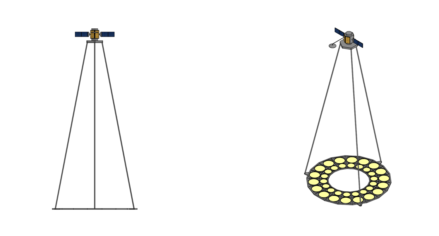
SDI Space System's Helios is a satellite-based surveillance network providing global, real-time infrared missile launch detection and tracking. The Helios constellation is organized into two complementary layers, a Helios High Layer that consists of four satellites: two in geostationary Earth orbit (GEO) and two in highly elliptical polar orbits (HEO) which provide persistent, global-scale infrared surveillance optimized for strategic missile launch detection and initial characterization, supplemented by a Helios Low Layer that consists of a larger constellation of satellites in low Earth orbit (LEO) that provide high-resolution tracking capability throughout all phases of ballistic missile flight, warhead-decoy discrimination during midcourse, and precision tracking and kill assessment data for missile defense interceptors.


The functions of the Helios High Layer include persistent global infrared surveillance, initial launch detection and characterization;, launch point estimation and impact point prediction, strategic early warning dissemination to national command authorities and combatant commands, and cuing data generation for Low Layer acquisition. The two primary GEO satellites in the High Layer are stationed at approximately 89°W and 163°E longitude, providing overlapping coverage across the Western and Eastern hemispheres. Each GEO satellite carries both a wide-field-of-view scanning sensor for rapid area surveillance and a narrow-field-of-view staring sensor for detailed event characterization. The on-orbit spare is maintained at a nearby parking longitude with the ability to drift to either operational slot within 30 days. The two HEO satellites operate in a Molniya-type orbit with an inclination of 63.4°, a semi-major axis producing a 12-hour period, and an argument of perigee of 270° such that apogee occurs over the Northern Hemisphere. The two satellites are phased 6 hours apart in their orbits, ensuring that at least one satellite is always near apogee and able to observe high-latitude regions (above 65°N) that are geometrically challenging for GEO sensors. This configuration provides persistent polar and sub-polar coverage critical for detecting submarine-launched ballistic missiles (SLBMs) from Arctic waters. The 63.4° inclination is specifically chosen to eliminate secular drift of the argument of perigee, maintaining stable orbital geometry without excessive station-keeping propellant expenditure.


Instruments:
Each Helios High Layer satellite (GEO and HEO) carries a dual-mode infrared payload consisting of a Wide-Field Scanning Sensor (WFSS) and a Focused Staring Sensor (FSS). Both sensors employ mercury cadmium telluride (HgCdTe) focal plane arrays cooled to cryogenic temperatures by a two-stage mechanical pulse-tube cryocooler system.

Wide-Field Scanning Sensor (WFSS): The WFSS employs a 60 cm aperture telescope with a dual band 4096 x 4096 pixel, 18 μm pixel pitch HgCdTe Focal Plane Array detector that supports, simultaneous dual-band SWIR (2.7–2.9 μm) and MWIR (3.5–4.2 μm) operation. The sensor has a 17.4° field of view providing full Earth disk coverage and employs a step-stare scan mechanism with fast-steering mirror. The WFSS is optimized for rapid detection of ballistic missile boost-phase signatures across the entire visible Earth disk with dual-band simultaneous imaging capability allowing immediate spectral characterization of detected events, enabling rapid classification of missile launches versus non-threat infrared events such as industrial flares, wildfires, and solar glint . The step-stare scan approach, combined with time-delay-integration (TDI) readout techniques, provides substantially higher sensitivity than legacy scanning sensors while maintaining the fast revisit rate required for timely detection.

Focused Staring Sensor (FSS): The FSS employs a 45 cm aperture telescope on an optical bench shared with the WFSS and contains a dual band 2048 x 2048 pixel HgCdTe Focal Plane Array detector that supports, simultaneous dual-band SWIR (2.7–2.9 μm) and MWIR (3.5–4.2 μm) operation. The FSS is designed for 10 μrad (GEO ground sample distance ~360 m) angular resolution with a 50 ms to 2 s per frame stare dwell time and can image up to 4 simultaneous stare regions via fast-steering mirror multiplexing, having the ability to detect post-boost vehicle and early midcourse objects against cold space background with streak detection, dim-target extraction, and intensity history recording functions. The FSS provides tasked, high-sensitivity observation of regions of interest identified by the WFSS or by external cuing sources and is used to characterize missile events in detail during late boost and early post-boost phases, providing initial estimates of threat complex composition and trajectory parameters for handoff to the Low Layer. The FSS can simultaneously monitor up to four discrete regions, enabling it to track multiple independent launches concurrently.

Each Helios satellite incorporates a radiation-hardened high-performance computing module based on a system-on-chip architecture combining general-purpose CPU cores with a large-scale field-programmable gate array (FPGA) fabric and a neural processing unit (NPU). The High Layer spacecraft employ a single processing module rated at approximately 50 TOPS. The onboard software follows a layered, modular architecture with a Sensor Interface Layer which Handles raw focal plane array readout, non-uniformity correction, bad-pixel replacement, and calibration, producing radiometrically calibrated image frames, a Detection Layer which implements matched-filter and constant false alarm rate (CFAR) detection algorithms optimized for the FPGA fabric, capable of processing full-frame data at sensor frame rates with sub-pixel centroid extraction, a Tracking Layer that maintains a multi-target tracking state using an interacting multiple model (IMM) estimator with extended Kalman filter banks, supporting simultaneous tracking of hundreds of objects with automatic track initiation, maintenance, and termination, a Discrimination Layer which utilizing both physics-based models and machine-learning classifiers trained on high-fidelity simulation data and validated against controlled test events using the neural processing unit to accelerates inference for deep-learning classification models, and the Data Fusion and Reporting Layer which fuses onboard track and discrimination products with externally received data (from other constellation satellites and ground-based sensors) and generates standardized tactical data messages for downlink. The onboard AI/ML subsystem employs a modular inference engine supporting both convolutional neural network (CNN) architectures for spatial pattern recognition and recurrent neural network (RNN) / transformer architectures for temporal sequence analysis. Models are trained on the ground using high-fidelity synthetic infrared scene generators calibrated against measured data, and are uploaded to the spacecraft via the secure command uplink. A model versioning and rollback capability ensures safe deployment of updated classifiers. The inference engine operates within a formally verified safety wrapper that constrains its output to predefined decision boundaries, ensuring that autonomous classification recommendations remain within validated performance envelopes and can be overridden by ground operators.


Spacecraft:
Satellite Bus: The Helios High satellite uses SDI Space System's S3000 commercial satellite bus, a high performance commercial communications satellite bus designed to operate in geostationary orbit. The Satellite bus features a composite primary structure with aluminum honeycomb panels, a nadir-pointing payload deck, and is fitted with a deployable sunshield for thermal and stray-light control. Electrical power is provided by a pair of Triple-junction GaAs solar arrays generating 12 kW EOL power with a 250 Ah lithium-ion Li-ion battery for eclipse operations, with power supplied via dual 28 V and 100 V power buses. Thermal control consists of an active cryocooler system for IR focal planes with variable-conductance heat pipes, multi-layer insulation, deployable radiator panels, and heater circuits for propulsion and electronics thermal management.

Attitude Control & Propulsion: The S3000 spacecraft is three-axis stabilized using its attitude determination & control system (ADCS) which includes three star trackers, two IMUs, four reaction wheels ( pyramid config), magnetic torque rods providing <100 μrad pointing accuracy and < 10 μrad pointing knowledge. Propulsion is provided by a Bipropellant main engine (445 N) for orbit raise and station-keeping with monopropellant RCS thrusters (22 N x 12) for attitude control and momentum management.

Communications: The Helios High communication systems include omnidirectional antennas and dual-band gimbaled spot beams which operate on three frequency bands including one at Ka-band, three at S-band, and one at Q-band. The Ka-band is used for mission and sensor data downlink. The S-band is utilized for theater mission downlink, backup space-ground-link-system (SGLS) telemetry downlink, and backup SGLS commanding. The Q-band is used for anti-jam commanding. All RF communications links employ spread-spectrum waveforms with frequency hopping and directional antenna nulling to resist jamming. Command uplinks utilize encryption with anti-spoof authentication protocols. The onboard communications controller implements autonomous link management, detecting interference and autonomously switching between primary, backup, and relay paths without ground intervention. Each Helios satellite is also equipped with four laser inter-satellite link (LISL) terminals, an intensity modulation and direct detection (IM/DD) optical communication system with a 1.55 µm vertical-cavity surface-emitting laser (VCSEL) with a peak transmit power of 1.0 W which lets the satellite communicate with other Helios satellites with a data transfer rate of 10 Gbit/s with homodyne BPSK (Binary Phase Shift Keying) optical modulation. The laser communications terminal itself weighs 40 kilograms and includes an optics unit (OU) with the 13 cm diameter laser telescope and both course and fine pointing mechanisms and a frame unit which contains the laser subsystem with twin solid-state laser diode pump modules, pointing, acquisition and tracking (PAT) controller, and EPC (Electrical Power Conditioner) module. The LCT also includes a 10 kg heat pipe radiator mounted to the frame unit for thermal management.


Ground Control:
The Helios ground segment is responsible for satellite command and control, mission data processing and exploitation, and integration with the broader missile defense command and control architecture. Major ground control elements include the Mission Control Center (MCC) which provides real-time satellite command and control, constellation health management, and anomaly resolution, the Mission Data Processing Center (MDPC)
with dispersed processing nodes to provide ground-based data fusion, advanced discrimination processing, archival and replay, and relay ground terminals which provide Ka-band and S-band uplink/downlink to the constellation. The ground processing pipeline receives both raw and onboard-processed data products. For the Helios High layer raw infrared imagery is downlinked and processed through a ground-based Infrared Event Processing System which performs independent detection and characterization as a cross-check against onboard results. The ground segment implements a federated data fusion architecture that correlates tracks and events reported by multiple Helios satellites, other space-based sensors, and other sensors.
Last edited by The Technocratic Syndicalists on Tue Apr 28, 2026 10:25 am, edited 4 times in total.
SDI AG
Arcaenian Military Factbook
Task Force Atlas
International Freedom Coalition


OOC: Call me Techno for Short
IC: The Kingdom of Arcaenia

User avatar
The Technocratic Syndicalists
Minister
 
Posts: 2349
Founded: May 27, 2015
Inoffensive Centrist Democracy

Postby The Technocratic Syndicalists » Fri May 26, 2017 11:35 pm

Image

TRS - 1A

General Characteristics:
  • Function: Hyperspectral Imaging Satellite
  • Dimensions: 5.3 m x 7.9 m x 7.9 m
  • Launch Mass: 2,635 kg
  • Electrical Power: 6.1 kW
  • Attitude Control: 3-axis momentum biased
  • Propulsion: 8x monopropellant hydrazine thrusters, 1 N each
  • Telemetry: Ka/X/S Band
Instruments:
  • Hyper Spectral Imager (1.1 m mirror, 0.25 m resolution, 280 spectral bands)
    • Visible band Si scanning focal plane array (60 bands, 5 nm spacing)
    • NIR HgCdTe scanning focal plane array (60 bands, 5 nm spacing)
    • SWIR HgCdTe scanning focal plane array (80 bands, 10 nm spacing)
    • MWIR HgCdTe scanning focal plane array (80 bands, 25nm spacing)
Orbital parameters:
  • Orbit height: 617 km
  • Orbit inclination: 97 o
  • Design Life: 7 years


Overview:
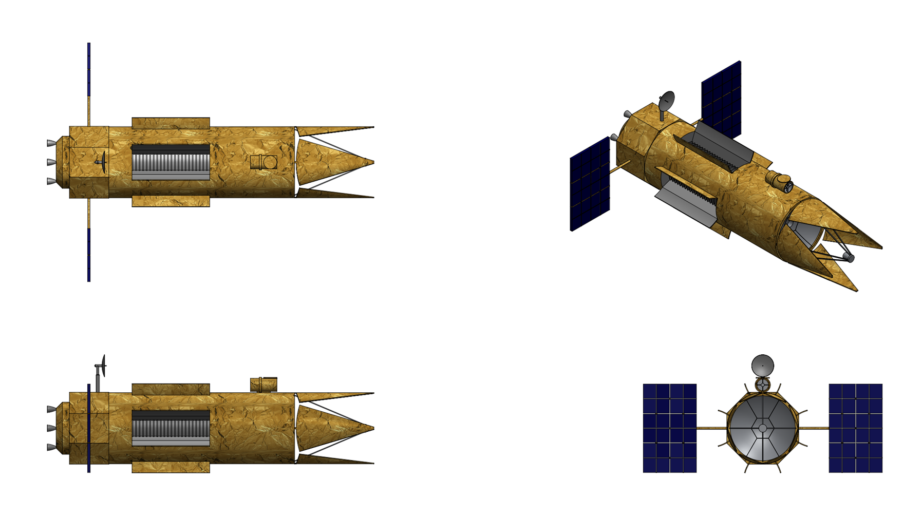
The SDI TRS-1A is a hyperspectral reconnaissance satellite designed by SDI Space Systems intended to provide persistent, high-resolution spectral intelligence from sun-synchronous low-Earth orbit. HyperSight-1 represents a significant advancement over legacy multispectral imaging platforms by combining a large-aperture 1.1-meter telescope with a state-of-the-art pushbroom hyperspectral imager spanning four spectral regions includinf visible (VIS), near-infrared (NIR), short-wave infrared (SWIR), and mid-wave infrared (MWIR). The design prioritizes radiometric stability, agile pointing for area collection, and onboard data processing to reduce downlink latency for time-critical intelligence products. Key performance figures include sub-meter ground sample distance (GSD) in panchromatic mode, spectral resolution better than 10 nm across 220+ contiguous bands, and a revisit time of less than 24 hours using off-nadir pointing. The platform is designed for a 7-year operational lifetime with consumables supporting up to 10 years of extended mission operations.


Instruments:
Optical Payload: The primary imaging system of the satellite is a 1.1-meter clear aperture Ritchey-Chrétien telescope operating at f/14.5. The optical system employs a two-mirror anastigmat design with a corrective element group near the focal plane to achieve diffraction-limited performance over the full field of view. The primary mirror (M1) is a lightweighted ULE (ultra-low expansion) glass substrate with an open-back isogrid architecture, reducing mass to approximately 68 kg while maintaining a surface figure error below 20 nm RMS. The secondary mirror (M2) is supported by a four-vane spider structure fabricated from CFRP with near-zero CTE in the axial direction. A six-axis hexapod actuator system on the M2 mount provides active wavefront correction, compensating for gravity release, thermal gradients, and long-term dimensional drift. Wavefront sensing is performed by a dedicated Shack-Hartmann sensor sampling the science beam via a dichroic pickoff. Downstream of the telescope focal plane, a dichroic beam-splitter assembly separates the collected light into four spectral channels, each feeding a dedicated pushbroom spectrometer module. This approach allows each spectrometer to be independently optimized for its spectral region, with matched detector technologies and thermal environments. The spectrometers employ an Offner relay configuration, which provides excellent spectral uniformity (smile < 0.1 pixel, keystone < 0.1 pixel) across the full spatial swath. Each spectrometer images a narrow entrance slit onto a two-dimensional focal plane array (FPA), where one axis records the spatial dimension and the orthogonal axis records the spectral dimension. The slit width is 12 µm, corresponding to the detector pixel pitch.

The four-channel architecture covers the electromagnetic spectrum from 400 nm to 5,000 nm with 280 contiguous spectral bands. The VIS channel (400–700 nm) employs a back-illuminated, frame-transfer silicon CCD with 12 µm pixels and 4,096 spatial elements per line. Time-delay integration (TDI) with 128 stages provides high signal-to-noise ratio (SNR > 300:1 at typical scene radiances) while maintaining the pushbroom line rate required at orbital velocity. The 60 contiguous spectral bands at 5 nm spectral sampling enable fine discrimination of vegetation health indices, mineral absorption features, and synthetic material signatures in the blue-green-red spectral region. The NIR channel (0.7–1.0 μm) shares a common CCD architecture with the VIS channel, employing enhanced deep-depletion silicon to maintain quantum efficiency above 60% out to 1,000 nm. The 60 bands at 5 nm sampling capture the red-edge chlorophyll reflectance plateau, water absorption features near 940 nm, and atmospheric correction bands. The NIR and VIS channels are co-registered to within 0.2 pixels through shared optical bench mounting. The SWIR channel (1–2.5 μm) employs a mercury cadmium telluride (MCT) focal plane array with a 2.5 µm cutoff wavelength, 2,048 spatial pixels at 18 µm pitch. The detector operates at 150 K, achieved via a dedicated single-stage Stirling cryocooler. The 80 spectral bands at 10 nm sampling cover critical mineralogical absorption features (clays, carbonates, sulfates), hydrocarbon signatures, and moisture indicators. SWIR SNR exceeds 150:1 at the design reference radiance. The MWIR channel (3-5 μm) employs a high-operating-temperature MCT detector with a 5.3 µm cutoff wavelength, operating at 120 K via a two-stage pulse-tube cryocooler. The 1,024-element spatial array at 24 µm pitch provides 80 spectral bands at 25 nm spectral sampling. This channel enables thermal target detection, gas plume identification (including CO₂, CH₄, and industrial effluents), and nighttime imaging capability independent of solar illumination. The MWIR channel achieves a noise-equivalent temperature difference (NETD) of less than 25 mK at 300 K scene temperature.

From a designed orbit altitude of 617 km the hyperspectral imaging system has a swath width of 13.2 km and can image a 66.5 km x 112 km (mono) or 26.6 km x 112 km (stereo) area with a ground resolution of 0.25-0.30 meters and pixel geolocation accuracy to <3.5 meters with the ability to collect up to 680,000 square kilometers of imagery per day. In addition to hyperspectral operation, the telescope supports a high-resolution panchromatic imaging mode by binning the VIS/NIR detector across all spectral bands while operating at maximum TDI depth. This yields a broadband panchromatic image at 0.34-meter GSD from the nominal orbit altitude, enabling detailed spatial analysis and pan-sharpening of hyperspectral data products. The panchromatic mode can be interleaved with hyperspectral collection on alternating scan lines for simultaneous pan+HSI data takes.


Spacecraft:
Satellite Bus:The TRS-1A uses an SDI Space System's S900 commercial satellite bu. The primary structure consists of a hexagonal aluminum honeycomb structure 5.3 meters in length and 2.5 meters in diameter with carbon fiber reinforced polymer (CFRP) longerons and shear panels at each vertex. A central optical bench, fabricated from ultra-low-CTE silicon carbide (SiC) composite, provides the metering structure for the telescope assembly and is kinematically isolated from the bus to mitigate thermo-elastic distortion. Six deployable solar array wings extend radially from the hexagonal bus, one from each face. Each wing comprises two articulated panels connected by a single-axis drive mechanism. This six-wing configuration provides several critical benefits over conventional two-wing designs: it eliminates asymmetric solar radiation pressure torques that complicate attitude control, maintains power generation across a wider range of body attitudes during agile imaging maneuvers, and provides N-1 redundancy (the satellite can sustain full mission operations with any five of six wings functional). Each array panel employs quadruple-junction inverted metamorphic (IMM4J) gallium arsenide solar cells with a beginning-of-life efficiency of 34.5%. The panels are deployed via shape memory alloy actuated hinges and locked by redundant latching mechanisms. The six deployable solar array wings provide a total beginning-of-life (BOL) power generation capacity of 6,400 W under worst-case solar incidence conditions. The cells are protected by 100 µm ceria-doped cover glass with anti-reflective and UV-rejection coatings. End-of-life (EOL) power after 7 years is projected at 5,440 W, accounting for 2.5% annual degradation from radiation damage and contamination. Energy storage is provided by two Li-ion battery packs with a combined capacity of 168 Ah (6,050 Wh) at 36 V nominal bus voltage. The batteries employ high-specific-energy nickel manganese cobalt (NMC) cells with individual cell monitoring and autonomous cell balancing. Maximum depth of discharge is limited to 30% during normal eclipse operations and 50% during extended eclipse seasons, providing comfortable margin for the required 38,000+ charge/discharge cycles over the 7-year mission. The batteries are thermally controlled by dedicated heat pipes routed to a radiator panel on the anti-sun side of the bus. A regulated 28 V ± 0.5% main bus supplies all spacecraft loads through a centralized Power Distribution Unit (PDU). The PDU incorporates solid-state power controllers (SSPCs) for each load, providing overcurrent protection, soft-start sequencing, and telemetry reporting. A dedicated unregulated high-voltage bus (100 V) supplies the ion thruster power processing unit, isolated from the main bus by a DC-DC converter to prevent thruster-induced conducted emissions from coupling into sensitive payload electronics.

The hexagonal bus structure of the S900 bus supports a zonal thermal design. The anti-sun face hosts the primary thermal radiator panels (total area 3.8 m²) for bus electronics and battery thermal rejection. Multi-layer insulation (MLI) blankets with 20-layer construction cover all external surfaces except radiators and solar arrays. The optical bench is thermally isolated from the bus by titanium flexure mounts and enclosed in a dedicated MLI shroud with proportional heater zones maintaining the telescope metering structure at 20°C ± 0.5°C. The SWIR detector cryocooler (single-stage Stirling, 5 W cooling at 150 K) and MWIR detector cryocooler (two-stage pulse-tube, 2 W cooling at 120 K) reject waste heat via dedicated cryocooler radiators on the anti-sun face, isolated from the bus radiators. The cryocoolers are mounted on vibration-isolated platforms with active vibration cancellation to prevent coupling micro-vibrations into the optical path. Loop heat pipes (LHPs) transport waste heat from the payload electronics module (dissipating up to 400 W) to the main radiator array. Survival heaters with thermostatic control maintain all components above minimum allowable flight temperatures during eclipse and safe-mode conditions.

Attitude Control & Propulsion: The S900 ADCS employs a multi-sensor architecture combining two star trackers (8 arcsecond accuracy, 10 Hz update), a high-precision milli-HRG (mHRG) Hemispherical Resonator Gyroscope package (0.001°/hr bias stability, 0.0001°/√hr angle random walk), coarse and fine sun sensors on each hexagonal face, and a three-axis magnetometer for safe-mode recovery. The star trackers are mounted on the optical bench to minimize alignment uncertainty between the attitude reference frame and the telescope boresight. Primary torque authority is provided by four control moment gyroscopes (CMGs) arranged in a pyramid configuration, delivering a maximum torque of 220 N·m and total angular momentum storage of 300 N·m·s. The CMG cluster supports the high-agility maneuver requirement while providing single-fault tolerance through the redundant fourth unit. Momentum desaturation is accomplished by three magnetic torque rods (50 A·m² each) interacting with the geomagnetic field. For fine pointing during imaging a fast-steering mirror (FSM) in the telescope optical path provides ±0.5° range at 200 Hz bandwidth, correcting residual jitter from CMG micro-vibrations. The propulsion system consists of four 22-N monopropellant hydrazine thrusters (two pairs, canted 15° for pitch/yaw authority) that provide impulsive delta-V for orbit maintenance, collision avoidance, and formation-keeping. Eight 1-N thrusters provide fine attitude control during safe mode and reaction wheel desaturation backup. The hydrazine is stored in a 300-kg-capacity titanium diaphragm tank pressurized with helium. The total delta-V budget from the chemical system is approximately 180 m/s, sufficient for 7 years of orbit maintenance with margin.

Communications: The primary data downlink consists of a Ka-band (26.5 GHz) high-gain antenna with a 0.6-meter reflector, achieving a maximum data rate of 1.8 Gbps to dedicated ground terminals. A secondary X-band (8.2 GHz) link at 800 Mbps provides backward compatibility with existing ground infrastructure and serves as a redundant downlink path. Telemetry, tracking, and command (TT&C) functions use an S-band (2.2 GHz) omnidirectional link at 256 kbps uplink / 1 Mbps downlink, providing continuous commanding access including during safe-mode and tumbling scenarios. An optical laser inter-satellite link (ISL) terminal operating at 1,550 nm enables relay of time-critical data through a constellation of data relay satellites in geosynchronous orbit, reducing tasking-to-delivery latency to under 10 minutes for priority collection requests.
Last edited by The Technocratic Syndicalists on Mon May 11, 2026 8:00 am, edited 11 times in total.
SDI AG
Arcaenian Military Factbook
Task Force Atlas
International Freedom Coalition


OOC: Call me Techno for Short
IC: The Kingdom of Arcaenia

User avatar
The Technocratic Syndicalists
Minister
 
Posts: 2349
Founded: May 27, 2015
Inoffensive Centrist Democracy

Postby The Technocratic Syndicalists » Sun May 28, 2017 9:57 pm

Image

OCULUS Enhanced Imaging Satellite

General Characteristics:
  • Function: Optical Imaging/SIGINT Satellite
  • Dimensions: 11.0 m x 10.5 m x 4.1 m
  • Launch mass: 22,500 kg
  • Electrical power: 18.5 kW
  • Attitude control: three-axis momentum biased
  • Propulsion:
    • 16x N2O4/MMH RCS thrusters, 22 N each
    • 2x N2O4/MMH main engines, 1000 N each
  • Telemetry: S/Ka Band
Instruments:
  • Three-mirror anastigmat telescope (3.2 m mirror, 0.08 m resolution)
    • High-Resolution Panchromatic Array (HRPA)
      • 16 x Visible/NIR Si CMOS, 9,216 x 9,216, 0.2 to 1.1 μm
    • Multispectral Imaging Array (MIA)
      • 8 x SWIR HgCdTe FPA, 4,096 x 4,096 px, 0.9 to 1.7 μm
      • 8 x MWIR/LWIR HgCdTe FPA, 4,096 x 4,096 px, 3 to 5 and 8 to 12 μm
  • 2 x Omnidirectional SIGINT Antennae (0.03 to 40 GHz)
Orbital parameters:
  • Orbit height: 820 km
  • Orbit inclination: 97 o
  • Orbit life: 15 years


Overview:
The OCULUS Enhanced Imaging Satellite is an advanced electro-optical and SIGINT reconnaissance satellite designed by SDI Space Systems. OCULUS integrates an advanced 3.2-meter primary aperture telescope with a wide-field mosaic focal plane array, enabling simultaneous high-resolution and wide-area search modes. The system achieves sub-centimeter ground sample distance (GSD) in its highest resolution mode while offering a dramatically expanded wide-field-of-view (WFOV) capability for persistent area surveillance. Major design drivers include survivability against the evolving counterspace threat environment, incorporating extensive nuclear hardening, laser-dazzle protection, and anti-satellite (ASAT) threat mitigation systems. The satellite also features advanced low-observable design principles to reduce its vulnerability to adversary space surveillance networks. A secondary signals intelligence (SIGINT) payload further provides complementary electronic intelligence collection from the same orbital platform.


Instruments:
Telescope:The Optical telescope of OCULUS constitutes the most advanced spaceborne optical system ever designed for a reconnaissance application. The telescope employs a modified Korsch three-mirror anastigmat (TMA) optical design, which provides a wide corrected field of view free of coma, astigmatism, and field curvature across the entire focal plane. The optical prescription consists of a concave hyperbolic primary mirror (M1), a convex hyperbolic secondary mirror (M2), a concave elliptical tertiary mirror (M3), and a set of flat fold mirrors used to package the optical path within the satellite structure. The system achieves an effective focal length of 28.5 meters with an f/number of f/8.9, providing the angular resolution necessary for sub-centimeter ground sampling. The unobscured off-axis TMA geometry eliminates diffraction artifacts from secondary mirror support structures, providing cleaner point-spread function characteristics than legacy on-axis designs.

The M1 primary mirror is a lightweight monolithic mirror with a clear aperture of 3.20 meters, fabricated from Corning ULE (Ultra-Low Expansion) fused silica glass. ULE is selected for its near-zero coefficient of thermal expansion (CTE < 10 ppb/K at 20 degrees C), ensuring dimensional stability across the thermal environment experienced in orbit. The mirror blank mass is reduced using an advanced open-back isogrid architecture, reducing the areal density of the system while maintaining the structural rigidity required for nanometer-level wavefront stability. The optical surface is figured to a wavefront error (WFE) of less than 18 nanometers RMS at the operational wavelength of 632.8 nm, corresponding to approximately lambda/35, ensuring diffraction-limited performance across the panchromatic imaging band. The reflecting surface consists of a protected silver coating optimized for high reflectivity (>98.5%) across the 0.4 to 2.5 µm spectral range, overlaid with a multilayer dielectric protective stack for resistance to atomic oxygen erosion and charged particle damage. The primary mirror is supported by a 36-point active figure control system using piezoelectric actuators bonded to the mirror reaction structure. These actuators provide closed-loop wavefront correction at up to 100 Hz bandwidth, compensating for thermal distortion, gravity release effects, and micro-vibration induced by onboard mechanisms. A Shack-Hartmann wavefront sensor located at the focal plane samples the wavefront from internal reference sources to drive the active optics control loop.

The M2 secondary mirror is a convex hyperbolic mirror also fabricated from ULE glass. It is mounted on a six-degree-of-freedom hexapod positioning mechanism that provides focus, tip/tilt, and decentering adjustment with sub-micrometer precision. The hexapod compensates for alignment drift caused by thermal gradients and launch-induced structural settling. The M3 tertiary mirror is a concave ellipsoid also of ULE construction. M3 is mounted on a three-axis tip/tilt platform and is positioned near the system pupil image, providing field-dependent aberration correction. All three mirrors feature integrated resistive heater circuits and platinum resistance temperature detectors (PRTDs) bonded to their rear surfaces to maintain thermal uniformity to within 0.05 K across each mirror body. Multi-layer insulation (MLI) blankets and active thermal louvers surround the telescope tube to minimize thermal gradients induced by solar illumination variations. The telescope optics are housed in a forward optics assembly (FOA) which contains the secondary mirror contained in its secondary mirror support structure, secondary mirror support tubes which form part of the secondary mirror 6-axis hexapod drive, primary mirror contained in the forward metering structure, aft metering structure which contains the digital camera electronics, alignment tube drives which act to align the forward and aft metering structures, and the main mounts which connect the forward optics assembly to the spacecraft. All forward optics assembly structures are constructed from Invar-36,a n iron-nickel alloy with an ultra-low coefficient of thermal expansion (CTE). The telescope is surrounded by an outer barrel assembly (OBA), an octagonal-shaped passively cooled radioactive structure surrounding the telescope which acts as combination environmental shield and thermal shield for the telescope. The outer barrel assembly is constructed from a zero CTE boron/cyanate composite consisting of boron fibers embedded in a cyanate siloxane resin. The secondary mirror support structure, secondary mirror support tubes, and both forward and aft metering structure also include electrical heaters which are used to control and eliminate any thermal gradients inside the telescope's optics.

The telescope focal plane assembly (FPA) employs a hybrid mosaic focal plane combining high-resolution panchromatic detectors with multispectral filter arrays, all integrated onto a single cryogenically cooled focal plane structure. The focal plane is divided into two primary detector zones. The first zone, the High-Resolution Panchromatic Array (HRPA), consists of a mosaic of 16 back-illuminated CMOS image sensors, each with 9,216 x 9,216 pixels at a 5.5 micrometer pixel pitch. The mosaic forms an effective array of approximately 36,864 x 36,864 pixels in the narrow-field high-resolution mode. CMOS technology is selected over CCD for its superior radiation tolerance, lower power consumption, on-chip analog-to-digital conversion, and ability to support windowed region-of-interest readout for agile tasking scenarios. The second zone, the Multispectral Imaging Array (MIA), consists of a separate mosaic of 8 mercury-cadmium-telluride (HgCdTe) detector arrays for the short-wave infrared bands and 8 mercury-cadmium-telluride (HgCdTe) detector arrays for the mid-wave and long-wave infrared bands. Each multispectral detector has 4,096 x 4,096 pixels at a 10 µm pixel pitch. A filter wheel and dichroic beamsplitter assembly routes light to the appropriate detector set. The entire focal plane assembly is maintained at an operating temperature of 180 K for the SWIR detectors and 80 K for the MWIR/LWIR HgCdTe detectors using a two-stage mechanical cryocooler system augmented by a passive radiator panel facing deep space. The cryocoolers are high-efficiency pulse tube units with a combined cooling capacity of 15 W at 80 K.

The OCULUS telescope supports both high-resolution narrow-field-of-view (NFOV) mode and wide-field-of-view (WFOV) swath modes. In the NFOV mode the full resolution of the telescope is utilized with the telescope at its native 28.5 m focal length. At the nominal perigee altitude of 265 km, this provides a ground sample distance (GSD) of approximately 5 cm panchromatic. Using sub-pixel dithering via fast steering mirror (FSM) micro-scanning across four exposures, the system synthesizes an effective GSD of approximately 2.5 cm. The field of view in this mode is 0.035° x 0.035°, providing an instantaneous ground footprint of approximately 1.9 km x 1.9 km. This mode is optimized for close-target identification and technical intelligence collection against high-priority fixed targets. In wide-field mode, a selectable optical relay reduces the effective focal length to 5,700 mm (f/1.78), illuminating the full extent of the wide-field detector mosaic. Wide field of view is 1.20° x 0.30° and provides a ground swath of approximately 65 km at perigee with a GSD of approximately 50 cm panchromatic resolution. This mode enables rapid wide-area search, battle damage assessment, and order-of-battle monitoring. The push-broom scanning geometry allows continuous strip imaging during a single orbital pass. Multispectral imaging is available in both narrow-field and wide-field modes, with GSD scaled by the ratio of multispectral to panchromatic pixel pitch (approximately 1.8x). The system provides 14 discrete spectral bands which enables material identification, camouflage detection, spectral change detection, vegetation health analysis, and chemical/biological agent identification when combined with atmospheric modeling.

SIGINT System:The OCCULUS signals intelligence subsystem provides a complementary electronic intelligence (ELINT) and communications intelligence (COMINT) collection capability, exploiting the OCCULUS's low-altitude orbital passes over denied territory. The SIGINT payload is designed to operate simultaneously with or independently of the primary optical imaging mission, enabling dual-phenomenology intelligence collection from a single platform. The SIGINT payload operates in a passive receive-only mode and consists of two primary antenna subsystems, a wideband digital receiver, and a dedicated signal processing unit. The antenna subsystem consists of a deployable parabolic mesh reflector antennas with collection capability in the 0.03 to 40 GHz range (VHF through Ka-band). The mesh reflector is a gold-plated molybdenum mesh design deployed by a perimeter truss structure. A multi-band feed assembly at the reflector focus provides dual circular polarization reception across the operating band. This antenna provides millimeter-wave signal collection capability against advanced adversary communications, radar, and data link systems. The SIGINT wideband digital receiver features instantaneous bandwidth of 2 GHz with tunable coverage across the full 0.03 to 40 GHz operating range. The receiver employs direct digital conversion using high-speed analog-to-digital converters (ADCs) sampling at 5 Gsamples/sec with 12-bit resolution. A reconfigurable digital signal processing (DSP) backend implemented on radiation-hardened FPGA fabric performs real-time signal detection, characterization, and classification using a continuously updated threat library. Signals of interest are tagged with precision time, frequency, bandwidth, modulation, and geolocation metadata, compressed, and stored onboard for downlink or forwarded in near-real-time via the laser relay link.


Spacecraft:
Satellite Bus:The OCULUS satellite employs a semi-monocoque design built around a central graphite-cyanate ester composite cylinder that serves as both the primary load path and the optical telescope metering structure. The use of high-modulus M55J carbon fiber in a cyanate ester resin matrix provides an extremely low coefficient of thermal expansion (CTE < 0.5 ppm/K), ensuring that the metering structure maintains optical alignment across the full range of orbital thermal environments without active compensation. The bus structure is designed to accommodate quasi-static launch loads of 6.0 g axial and 2.5 g lateral with positive structural margins on all primary members. The satellite is divided into three primary structural modules: The Forward Optics Assembly (FOA) housing the optical train and focal plane assembly, the Forward Equipment Module (FEM) housing avionics, reaction wheels, and star trackers, and the Aft Propulsion Module (APM) containing the propellant tanks, thrusters, and main engine. This modular architecture facilitates parallel integration and test at the factory level and enables on-orbit servicing operations.

The Spacecraft is designed to provide continuous power throughout all orbital and operational scenarios, including sustained eclipse periods and high-power imaging operations. The primary power source is a pair of deployable solar array wings, each consisting of three panels of advanced triple-junction inverted metamorphic (IMM) gallium indium phosphide / gallium arsenide / germanium (GaInP/GaAs/Ge) solar cells with a beginning-of-life (BOL) efficiency of 33.5%. Total solar array area is 64 square meters, providing 22.4 kW BOL and approximately 18.5 kW at end of life (EOL) after accounting for radiation degradation and thermal derating. Energy storage is provided by two lithium-ion battery packs with a combined capacity of 560 amp-hours (8.1 kWh) at a bus voltage of 52 V. The batteries are sized to support full spacecraft and payload operations through the maximum eclipse duration of 36 minutes with a maximum depth-of-discharge (DOD) of 30%, ensuring a cycle life of greater than 80,000 charge-discharge cycles over the 15-year mission. The power conditioning and distribution unit (PCDU) regulates the unregulated bus to a 28 V +/- 0.5% regulated bus for sensitive avionics loads and a separate 120 V bus for the electric propulsion system power processing units.

The spacecraft thermal control system maintains all spacecraft components within their operational temperature limits across the full range of orbital conditions. The TCS employs a combination of passive and active thermal control elements. Passive elements include multi-layer insulation (MLI) blankets, optical solar reflectors (OSRs), and high-emissivity radiator panels. Active elements include variable-conductance heat pipes (VCHPs), loop heat pipes (LHPs), thermoelectric coolers, and resistance heaters with proportional-integral-derivative (PID) controllers.
The telescope thermal environment is managed by a dedicated telescope thermal enclosure with active temperature control to maintain the metering structure within 0.1 K of its nominal set point. The primary mirror temperature gradient is maintained to less than 0.05 K through a combination of isothermalizing heat pipes embedded in the mirror support cell and active heater zones. A dedicated deep-space-facing cryogenic radiator provides passive cooling for the first stage of the focal plane cryogenic system.

Attitude Control & Propulsion: The OCULUS attitude determination & control system designed to provide the exceptional pointing accuracy and stability required for sub-centimeter resolution imaging. The system employs a hierarchical control architecture combining coarse body pointing with fine-stage optical stabilization. Coarse attitude control is provided by six (four active plus two spare) control moment gyroscopes (CMGs) in a pyramid configuration, providing a total angular momentum storage capacity of 3,200 N-m-s and a maximum torque output of 400 N-m. The CMGs enable rapid retargeting, allowing the telescope to slew between imaging targets at rates up to 3.5 °/s and settle to imaging accuracy within 4 seconds for a 30°maneuver. Attitude determination is provided by a suite of three star trackers with 0.5 arcsecond accuracy, a radar altimeter, four course sun sensors, three CMOS horizon sensors, twin hemispherical resonator gyroscope (HRG) inertial measurement unit (IMU) with gyro bias stability of <0.001° per hour, and a GPS receiver for coarse attitude initialization. The fine-stage stabilization system uses a fast steering mirror (FSM) in the optical train, driven by a high-bandwidth control loop fed by the focal plane guide sensor (a dedicated quad-cell detector array on the focal plane), achieving image motion compensation (IMC) to less than 1 microradian RMS across a 10 Hz to 500 Hz bandwidth.

The OCULUS spacecraft propulsion system uses a pair of 1,000-N main bipropellant engines burning monomethylhydrazine (MMH) and mixed oxides of nitrogen (MON-3). The main engine provides a specific impulse of 320 seconds. Sixteen 22-N bipropellant thrusters arranged in four clusters provide 3-axis translational and attitude control. Total bipropellant propellant load is 5,300 kg stored in six composite overwrapped pressure vessel (COPV) tanks with pressurized helium as the pressurant. The chemical propulsion system provides a total delta-V budget of approximately 850 m/s, sufficient for initial orbit insertion corrections, orbit maintenance for the full 15-year design life, and an extensive evasive maneuver reserve.

Communications: The communication systems of the OCULUS features a multi-tier communications architecture supporting both direct downlink to ground stations and relay through the relay satellite constellations. The primary imagery downlink uses a laser communication terminal (LCT) operating at 1550 nm wavelength with a data rate of up to 100 Gbps, enabling near-real-time delivery of high-resolution imagery to national intelligence consumers. A secondary Ka-band (26.5 GHz) RF downlink provides 3.2 Gbps direct-to-ground capability through two steerable 0.7 m Ka-band parabolic antennas. An S-band telemetry, tracking, and command (TT&C) link provides housekeeping telemetry downlink at 4 Mbps and encrypted command uplink at 256 kbps. All communication links employ encryption at the physical layer. The onboard data handling system is built around a radiation-hardened system-on-chip processors, providing onboard image processing capabilities including compression (JPEG2000), orthorectification, cloud detection and masking, and automated target recognition (ATR) cueing. Onboard mass data storage capacity is 128 terabytes using radiation-hardened NAND flash solid-state recorders in a RAID-5 configuration.


Survivability & Hardening:
The OCULUS is designed to survive and continue operations following a high-altitude nuclear detonation in the near-space environment. The entire spacecraft is enclosed in a continuous electromagnetic shielding enclosure functioning as a Faraday cage, constructed from aluminum alloy panels with a minimum thickness of 2.0 mm, bonded at all seams with conductive EMI gaskets providing a minimum shielding effectiveness of 80 dB at 1 GHz. All electrical penetrations through the shielding enclosure, including cable harness connectors, waveguide feeds, and antenna ports, are protected by transient suppression devices rated for the HEMP E1 environment (50 kV/m peak field, 2.5 ns risetime). Critical avionics boxes employ internal zoning with additional local shielding, ensuring cumulative EMP attenuation exceeds 100 dB for the most sensitive digital electronics. Radiation hardening consists of all mission-critical electronic components being specified to a total ionizing dose (TID) tolerance of at least 300 krad(Si) and a single-event latchup (SEL) threshold exceeding 75 MeV-cm2/mg linear energy transfer (LET), achieved through a combination of radiation-hardened-by-design (RHBD) semiconductor fabrication processes, spot shielding with tantalum and tungsten enclosures around the most sensitive devices, and comprehensive single-event effects (SEE) mitigation through triple-modular redundancy (TMR), error-detection-and-correction (EDAC) memory protection, and watchdog timer circuits. The optical focal plane detectors are protected by a graded-Z shielding stack (aluminum/tantalum/lead) around the focal plane enclosure, limiting the detector TID to less than 20 krad(Si) over the 15-year mission in the combined natural and enhanced radiation environment. The structural design accounts for X-ray impulse loading from a nuclear detonation at distances consistent with the specified threat scenarios. The primary structure incorporates X-ray energy absorbing layers consisting of carbon-carbon composite facesheets over a titanium honeycomb core at critical locations, designed to spread the impulse load and prevent localized structural failure. The thermal protection system for the nuclear scenario includes sacrificial ablative coatings on exposed external surfaces and autonomous safing sequences that close the telescope aperture door and stow sensitive deployables within 200 milliseconds of a nuclear detonation detection by the onboard nuclear event detection (NED) sensor suite.

The OCULUS satellite employs multiple layers of laser protection intended to protect the spacecraft from ground based laser dazzling or laser weapon systems. The first layer is a fast-acting electro-chromic shutter assembly located at the telescope entrance aperture, capable of reducing transmission by 60 dB (factor of one million) within 50 microseconds of a laser illumination detection event. The shutter is triggered by a dedicated laser warning receiver (LWR) consisting of a ring of photodiodes at the telescope aperture that detects coherent laser illumination from below. The second layer consists of narrow-band rejection (notch) filters in the optical train, permanently installed to block the most common threat laser wavelengths at 532 nm (frequency-doubled Nd:YAG), 1,064 nm (Nd:YAG fundamental), and 1,550 nm (erbium fiber laser). These filters are fabricated using multi-cavity thin-film interference technology, providing greater than 50 dB rejection at the blocked wavelengths with less than 5% transmission loss in the passband. The third layer is a sacrificial protective window at the focal plane, fabricated from synthetic sapphire with a broadband anti-reflection coating, designed to absorb a direct laser hit and protect the underlying detector arrays. The window is replaceable via an onboard carousel mechanism that carries two spare windows. A fourth layer is provided by mission planning, including the ability to predict and avoid known laser weapon engagement zones, and operational procedures to slew the telescope off-target during periods of assessed laser illumination risk.

OCULUS also incorporates several features to enhance survivability against kinetic direct ascent and co-orbital anti-satellite threats. The satellite carries a comprehensive space situational awareness (SSA) sensor suite consisting of a wide-field-of-view infrared threat warning sensor (TWS) providing hemispherical coverage in the 3-5 micrometer MWIR band, capable of detecting approaching kinetic kill vehicles (KKVs) and co-orbital inspection/attack satellites at ranges exceeding 1,000 km. Upon detection of an approaching threat, the satellite can execute pre-programmed evasive maneuvers using its chemical propulsion system, with a total allocated evasive delta-V reserve of 200 m/s. The onboard autonomous threat assessment and response system can initiate evasive maneuvers within 30 seconds of threat confirmation without requiring ground command uplink, ensuring response capability even during communications gaps. Additional ASAT countermeasures include a chaff and decoy dispensing system capable of deploying radar-reflective chaff clouds and small signature-enhanced decoy satellites to confuse adversary tracking systems. The satellite also carries 8 single-use deployable inflatable decoys that replicate the OCULUS's radar and infrared signature to dilute adversary targeting solutions.


Signature Reduction:
OCULUS incorporates comprehensive signature reduction measures to minimize its detectability by adversary space surveillance networks (SSNs), including ground-based radars, ground-based electro-optical telescopes, and space-based surveillance sensors. The satellite's exterior geometry has been designed using computational electromagnetic (CEM) modeling to minimize specular radar returns from the L through Ku-band frequencies used by space surveillance radars. Key design features include planar faceted exterior panel surfaces angled to deflect radar energy away from the monostatic radar direction, elimination of right-angle corner reflectors and flat surfaces normal to typical observation geometries, and radar-absorbing material (RAM) coatings on all external surfaces. The RAM treatment uses a multi-layer Dallenbach absorber consisting of a carbon-loaded polyurethane base layer and a magnetic iron carbonyl frequency-selective surface layer, providing a minimum 15 dB RCS reduction across the 2 to 18 GHz band. The combined effect of shaping and RAM treatment reduces the broadside radar cross section from an estimated 35 dBsm for an untreated satellite to less than 10 dBsm, a reduction factor of approximately 300.

The optical signature reduction features of OCULUS are designed to avoid detection by ground-based electro-optical space surveillance telescopes and space-based SSA sensors. All external surfaces not requiring specific thermal properties are coated with a ultra-low-reflectivity (ULR) black coating with a solar absorptance greater than 0.99 and a hemispherical reflectance of less than 0.01 across the 0.3 to 2.5 micrometer band. The coating formulation is Vantablack-derived on carbon nanotube forest technology applied via chemical vapor deposition. Solar arrays use back-surface reflector cells that minimize specular glint from the array panels, and the array rear surfaces are coated with ULR coating. The telescope aperture features a sunshade extending 3.5 meters forward of the primary mirror, with internal vanes coated in ULR material, to prevent solar illumination of the primary mirror and internal optical surfaces that could create a detectable glint event. The satellite's mission planning software includes a predictive solar exclusion zone calculator that commands the satellite to orient away from geometries that would produce specular reflections toward known adversary observation sites.

The thermal signature of the spacecraft is managed to reduce its contrast against the deep-space background in the mid-wave and long-wave infrared bands. Hot components such as power processing electronics and transmitter amplifiers are thermally coupled to radiator panels that face away from the Earth and away from predicted adversary observation geometries. The spacecraft thermal design maintains the maximum external surface temperature below 280 K on sunlit surfaces and below 180 K on shaded surfaces, minimizing the integrated MWIR and LWIR photon flux visible to off-platform infrared sensors. OCULUS also implements strict emission control (EMCON) protocols to minimize its radio-frequency detectability. All communications transmissions are scheduled for minimum duration, use directional antennas pointed away from adversary RF collection satellites, and employ spread-spectrum and frequency-hopping waveforms that reduce the signal's spectral power density below the detection threshold of known adversary SIGINT platforms. The satellite can operate in a full EMCON mode, suspending all RF transmissions and storing collected data onboard for delayed downlink when the satellite passes over friendly ground stations, for periods of up to 72 hours.
Last edited by The Technocratic Syndicalists on Thu May 07, 2026 7:26 am, edited 13 times in total.
SDI AG
Arcaenian Military Factbook
Task Force Atlas
International Freedom Coalition


OOC: Call me Techno for Short
IC: The Kingdom of Arcaenia

User avatar
The Technocratic Syndicalists
Minister
 
Posts: 2349
Founded: May 27, 2015
Inoffensive Centrist Democracy

Postby The Technocratic Syndicalists » Sun Jun 25, 2017 10:24 pm

Image

Liberty

General Characteristics:
  • Function: Internet Satellite
  • Dimensions: 2.8 m x 1.4 m x 10.0 m
  • Launch Mass: 260 kg
  • Electrical Power: 3.0 kW
  • Attitude Control: 3-axis momentum biased
  • Propulsion: 1x 90 mN hall-effect thruster
  • Telemetry: Ka/Ku/V Band
Electronics:
  • 2x Ku band phased array communications antennas (12.15 – 12.25 GHz downlink, 13.85 – 14.00 GHz uplink)
  • 2x Ka band phased array communications antennas (27.5-29.1 GHz downlink, 29.5-30 GHz uplink)
  • 2x V band parabolic antennas (37.5-37.75 GHz downlink, 47.2-47.45 GHz uplink)
Orbital parameters:
  • Orbit height: 340 km
  • Orbit inclination: 53.2 o
Last edited by The Technocratic Syndicalists on Wed Nov 04, 2020 7:28 pm, edited 10 times in total.
SDI AG
Arcaenian Military Factbook
Task Force Atlas
International Freedom Coalition


OOC: Call me Techno for Short
IC: The Kingdom of Arcaenia

User avatar
The Technocratic Syndicalists
Minister
 
Posts: 2349
Founded: May 27, 2015
Inoffensive Centrist Democracy

Postby The Technocratic Syndicalists » Thu Jun 29, 2017 2:40 pm

Image

Helios Low

General Characteristics:
  • Function: Missile Early Warning Satellite
  • Dimensions: 14.8 m x 5.0 m x 3.6 m
  • Launch Mass: 1,600 kg
  • Electrical Power: 5.2 kW
  • Telemetry: S/Ka Band
  • Attitude Control: 3-axis momentum biased
  • Propulsion:
    • 2x Xenon Hall-Effect Thrusters, 70 mN each
    • 12x Nitrogen cold-gas thrusters, 0.5 N each
Instruments:
  • SWIR/MWIR/LWIR HgCdTe scanning focal plane array
  • [i] SWIR/MWIR/LWIR HgCdTe starring focal plane array
Orbital parameters:
  • Orbit height: 1,000 km
  • Orbit inclination: 84 o


Overview:
SDI Space System's Helios is a satellite-based surveillance network providing global, real-time infrared missile launch detection and tracking. The Helios constellation is organized into two complementary layers, a Helios High Layer that consists of four satellites: two in geostationary Earth orbit (GEO) and two in highly elliptical polar orbits (HEO) which provide persistent, global-scale infrared surveillance optimized for strategic missile launch detection and initial characterization, supplemented by a Helios Low Layer that consists of a larger constellation of satellites in low Earth orbit (LEO) that provide high-resolution tracking capability throughout all phases of ballistic missile flight, warhead-decoy discrimination during midcourse, and precision tracking and kill assessment data for missile defense interceptors.

The functions of the Helios Low Layer include precision midcourse tracking of ballistic missiles, multi-spectral discrimination of warheads from decoys, debris, and missile bodies, generation of weapon-quality track data for ballistic missile defense interceptors, real-time interceptor fire control support, post-intercept kill assessment including hit confirmation and residual threat identification, and tracking of maneuvering hypersonic threats. The Low Layer consists of 24 satellites distributed across multiple orbital planes at an altitude of 1,000 km. The constellation geometry is designed using a modified Walker-Delta pattern to optimize both global coverage and multi-satellite simultaneous visibility of targets in midcourse flight. At 1,000 km altitude, each Low Layer satellite has a ground footprint radius of approximately 3,100 km for a 25° minimum elevation angle, enabling multiple satellites to simultaneously observe the same target within the midcourse volume above the atmosphere, enabling multi-satellite stereo triangulation and providing the geometric diversity needed to produce high-quality three-dimensional track estimates to resolve warhead-decoy ambiguities through differential angular observations.


Instruments:
Wide-Field Acquisition Sensor (WFAS): Each Helios Low Layer satellite carries a Wide-Field Acquisition Sensor (WFAS) which provides each Low Layer satellite with an independent boost-phase detection capability, enabling the constellation to autonomously detect and report missile launches without dependence on cuing from the High Layer GEO/HEO satellites. The sensor employs a wide-field-of-view scanning refractive telescope with only a single moving element , a rotating scan mirror, to sweep the sensor's instantaneous field of view across the full horizon-to-horizon coverage zone. The WFAS is optimized for detection of the short-wave infrared (SWIR) emission signatures characteristic of rocket motor plumes including detection of short-range, short-burn-time threats and employs a combination of fast scan revisit, high sensitivity, and advanced onboard clutter rejection algorithms tuned to reject dense terrestrial infrared backgrounds.
The WFAS telescope is a multi-element refractive design employing radiation-hardened optical glasses and crystalline infrared-transmitting materials selected for high transmission in the SWIR spectral band and resistance to darkening from the LEO radiation environment. The optical train starts with a single flat rotating scan mirror, 22 cm in diameter, mounted at 45° to the optical axis on a precision brushless DC motor bearing assembly which rotates continuously at a controlled rate to sweep the telescope line of sight in a conical scan pattern covering the full horizon-to-horizon field of regard. The mirror surface is gold-coated for high SWIR reflectivity and incorporates an optical encoder providing angular position knowledge to better than 5 arcseconds. This is the only moving element in the entire optical system. A four-element lens objective lens group (two calcium fluoride and two infrared-grade fused silica elements) with a clear aperture diameter of 18 cm and an effective focal length of 40 cm, provides the primary image-forming capability. The lens group is athermalized through selection of complementary thermal expansion and refractive index coefficients, maintaining focus across the operational temperature range of 15°C to 30°C without active focus adjustment. A two-element field-corrector lens group is positioned immediately ahead of the focal plane array to flatten the image field and correct residual off-axis aberrations (coma and astigmatism) across the full instantaneous field of view. The spectral filter assembly consists of a fixed narrowband filter stack bonded to the field corrector, defining the SWIR passband at 2.65–2.95 μm with out-of-band rejection exceeding OD 5. A secondary filter position at 2.0–2.4 μm is available via a commandable filter slide (the only other mechanism besides the scan mirror, but not part of the scanning optical path) for alternate phenomenology collection. A multi-vane baffle tube also extends forward of the scan mirror to reject direct and scattered solar and lunar illumination. Internal baffle vanes are coated with Aeroglaze Z306 absorptive coating. The baffle design ensures that the sun exclusion angle is ≤ 25° from the optical axis. The rotating scan mirror of the WFAS sweeps the telescope’s 2.8° × 2.8° instantaneous field of view in a continuous conical scan pattern. As the mirror completes each revolution, the scan trace covers an annular band on the celestial sphere. By slightly nutating the rotation axis of the mirror across successive revolutions (via a small piezoelectric tilt actuator on the bearing mount, which itself is not part of the optical path), the annular bands are interleaved to fill the full ±62° from nadir hemisphere within a single scan cycle. This produces complete horizon-to-horizon coverage below the spacecraft with a scan revisit period of 3.0 seconds at the baseline rotation rate of 120 RPM. At 1,000 km orbital altitude, the horizon-to-horizon field of regard corresponds to a ground coverage footprint diameter of approximately 6,200 km, enabling each satellite to surveil an area of roughly 30 million square kilometers per scan cycle. The overlap between successive scans ensures that no gap in coverage exists, even for objects near the edge of the field of regard where geometric sensitivity is lower.

The HgCdTe focal plane array used by the WFAS is a 2048 × 2048 pixel Mercury Cadmium Telluride (HgCdTe) FPA with a 25 μm pixel pitch and is fabricated using molecular beam epitaxy on a cadmium zinc telluride substrate, providing the low defect density necessary for the large-format array. The ROIC supports multiple readout modes: full-frame readout for survey scanning, windowed sub-array readout for rapid revisit of detected events, and on-chip time-delay-integration (TDI) of up to 8 stages to improve signal-to-noise ratio for dim targets by accumulating signal as the scan sweeps the image across pixel rows. The FPA employs a completely passive cryogenic cooling system for the SWIR focal plane array, eliminating the need for a mechanical cryocooler, its associated vibration, power consumption, and wear-out failure modes. The passive cooling system consists of two integrated subsystems: a cryoradiator and a cryogenic heat pipe network. The cryoradiator is a multi-stage passive radiator assembly deployed from the anti-sun side of the spacecraft after launch. It consists of three nested radiator stages, each thermally isolated from the next by low-conductivity support struts and multi-layer insulation (MLI) blankets. The outer stage consists of a large-area aluminum honeycomb panel (0.8 m² radiating area) with a high-emissivity surface coating (Aeroglaze A276, ε ≥ 0.92) radiating to deep space. This stage intercepts parasitic heat loads from the spacecraft bus and the Sun-illuminated environment, maintaining an intermediate temperature of approximately 220 K. The intermediate stage ( A smaller panel, 0.4 m²) nested within the outer shield, thermally connected only through low-conductivity G-10 fiberglass standoffs. This stage radiates through the aperture defined by the outer shield to the cold sky background, achieving approximately 170 K. The innermost radiator panel (0.25 m²) with a specialized low-α/ε surface coating (vapor-deposited silver with silicon monoxide overcoat, αs/εIR ≤ 0.08) achieving the target focal plane operating temperature of 150 K. This stage is connected to the FPA via the cryogenic heat pipe assembly. The cryoradiator assembly includes deployable sun shields that maintain a cold-sky view factor exceeding 0.85 for the cold stage at all orbital beta angles. An Earth-shade baffle prevents direct Earth infrared radiation from illuminating the cold stage. The total deployed span of the cryoradiator assembly is approximately 1.4 m from the spacecraft bus. The thermal path from the focal plane array to the cryoradiator cold stage is provided by a network of cryogenic axially grooved aluminum heat pipes charged with ethane working fluid. The heat pipes transport the FPA’s dissipated heat (approximately 1.5 W at the focal plane) and any conducted parasitic heat loads from the telescope structure to the cryoradiator cold stage with minimal temperature gradient. The heat pipe system is also designed with a high length-to-cross-section ratio and low-conductivity mounting interfaces to minimize conducted parasitics from the warm telescope structure to the cold FPA. The heat pipe mounting brackets use titanium flexures to provide mechanical support while limiting thermal conduction. The inherent isothermal behavior of the two-phase heat pipe working fluid also provides passive temperature regulation at the FPA, smoothing orbital thermal transients. The FPA temperature varies less than ±2 K over a full orbit, including eclipse transitions, without active heater control during nominal operations.
The heat pipe network consists of three independent parallel heat pipes, any two of which are sufficient to maintain the FPA within its operational temperature range, which provides single-fault tolerance for the cryogenic thermal path.

The WFAS onboard processing chain converts raw focal plane data into detection reports within a single scan cycle, achieving the low latency necessary for rapid alerting. Non-Uniformity Correction (NUC) first uses per-pixel gain and offset correction applied in the ROIC and in the FPGA-based focal plane electronics using calibration tables updated every 24 hours from onboard blackbody reference sources. Background estimation and subtraction uses an aaptive spatial-temporal background estimation using running median filters and principal component analysis (PCA) to model and subtract slowly varying terrestrial and atmospheric backgrounds, isolating transient infrared events. A multi-stage clutter rejection pipeline then targets known false alarm sources: solar glint from water and cloud surfaces, industrial thermal sources (refineries, smelters), gas flares, and wildfires. Each clutter type is addressed by a tuned rejection filter combining spatial extent, temporal persistence, spectral band ratio, and geographic exclusion zone databases stored in onboard memory. Constant false alarm rate (CFAR) detection is then applied to the background-subtracted imagery using matched filter templates corresponding to rocket plume point-source and extended-source signatures at various slant ranges and viewing geometries. Sub-pixel centroid estimation provides detection position to better than 0.3 pixel accuracy. Detected events are classified using a multi-feature decision tree followed by a neural network classifier. Features include: peak intensity, spatial extent, spectral band ratio, temporal profile (rise time, plateau, decay), angular rate relative to celestial background, and geographic correlation with known launch sites. Classification categories include: ICBM launch, IRBM/MRBM launch, SRBM launch, rocket artillery salvo, space launch vehicle, atmospheric re-entry, and non-threat event. Confirmed launch detections trigger automatic generation of standardized alert messages containing: detection time, estimated launch coordinates, preliminary threat classification, estimated azimuth and confidence level. Messages are queued for immediate downlink and simultaneously transmitted to the PTDS subsystem for cueing.

Precision Tracking and Discrimination Sensor: In addition to the Wide-Field Acquisition Sensor (WFAS) each Helios Low Layer satellite carries a multi-spectral Precision Tracking and Discrimination Sensor which provides the high-resolution, multi-spectral tracking and discrimination capability of the system. Mounted on a high-agility two-axis gimbal, the PTDS is a staring infrared sensor operating in four simultaneous spectral bands spanning from short-wave through long-wave infrared and is designed to track objects from late boost phase through midcourse and into terminal phase, discriminate warheads from decoys and debris, provide weapon-quality fire control tracks for missile defense interceptors, perform kill assessment following intercept events, and maintain track on maneuvering hypersonic glide vehicles and cruise missiles throughout their flight. The PTDS employs a 40 cm all-reflective three-mirror anastigmat telescope providing diffraction-limited imaging across all four spectral bands simultaneously. The telescope provides a 1.2° x 1.2° field of view with 5 μrad (ground sample distance~5 m from 1,000 km) resolution with a ±60° field of view from nadir in both elevation and azimuth via two-axis stabilized gimbal. The gimbal’s high slew rate and acceleration enable rapid retasking of the PTDS from one tracked object cluster to another, supporting the requirement to maintain tracks on multiple geographically dispersed threat complexes. The active vibration isolation system uses six voice-coil actuators in a Stewart platform configuration to attenuate bus-induced disturbances (from reaction wheels, cryocoolers, and thruster firings) to levels compatible with the sub-microradian jitter requirement. A payload-mounted star tracker and fiber-optic gyroscope inertial measurement unit, mechanically coupled to the telescope structure rather than the bus, provide the high-accuracy pointing knowledge needed for precision track estimation. All mirrors of the telescope are constructed from a beryllium substrate with electroless nickel plating, diamond-turned and polished with a protective gold plating. (reflectivity ≥ 98% from 1.5 to 12 μm). After the tertiary mirror of the TMA, the converging beam enters the aft-optics module where dichroic beamsplitters separate the light into four spectral channels, each directed to a dedicated focal plane array. The focal plane arrays consists of one 2048×2048 pixel InGaAs (SWIR-1) and 3x 2048×2048 pixel HgCdTe (SWIR-2, MWIR, LWIR) Focal Plane Arrays covering the SWIR (1.5–1.8 μm and 2.7–2.9 μm), MWIR (3.5–5.0 μm) and LWIR (7.5–10.5 μm) bands. The use of four separate focal plane arrays enables optimization of each detector for its spectral band and allows independent frame rates, integration times, and readout modes per channel. The SWIR-1 channel employs an Indium Gallium Arsenide (InGaAs) detector that requires only modest cooling to 200 K via a three-stage thermoelectric cooler, reducing the load on the mechanical cryocooler system. The SWIR-2 and MWIR channels use HgCdTe arrays with composition tuned for their respective cutoff wavelengths. The LWIR channel uses HgCdTe fabricated in the High Density Vertically Integrated Photodiode (HDVIP) architecture, which provides low dark current at higher operating temperatures than conventional planar architectures. The SWIR-1 channel incorporates a rotating polarimetric filter wheel with four positions: three linear polarization orientations (0°, 60°, 120°) and one open (broadband) position. The filter wheel is positioned in the collimated beam space between the dichroic beamsplitter and the SWIR-1 focusing optic, and rotates synchronously with the SWIR-1 frame rate. By acquiring three successive frames through the three polarization orientations, the system constructs the Stokes parameters (S0, S1, S2) and degree of linear polarization (DoLP) for each pixel. Polarimetric observables enhance discrimination by exploiting differences in polarized reflectance between metallic reentry vehicle surfaces, dielectric decoy materials, and multilayer insulation fragments. The PTDS cooling system is a four-stage Stirling-cycle cryocooler assembly consisting of two redundant cryocooler units (primary and backup), each capable of independently meeting the full cooling load. The dual-opposed linear compressor architecture cancels compressor vibration to first order; residual vibration is further attenuated by an active vibration cancellation system using accelerometers and piezoelectric counter-mass actuators on the compressor body. The cryocooler heat is rejected to the spacecraft thermal control system via conductive coupling to dedicated radiator panels on the anti-nadir face of the spacecraft bus. Thermal switches enable cross-strapping of either cryocooler unit to any cold load, providing graceful degradation in the event of a partial cryocooler failure.

For ballistic missile targets following predictable Keplerian trajectories during midcourse, the PTDS employs an Interacting Multiple Model (IMM) estimator using a bank of Extended Kalman Filters (EKFs). Each EKF in the bank implements a different dynamic model spanning the range of expected ballistic trajectories, from minimum-energy loft trajectories to depressed trajectories. The IMM algorithm maintains a probability-weighted mixture of these filters, autonomously adapting to the observed trajectory without requiring a priori knowledge of the specific missile type. The filter bank processes angular measurements from the PTDS (which provides bearing but not range as a passive infrared sensor) and fuses these with angular measurements from other Helios Low Layer satellites observing the same target via the inter-satellite link network, enabling stereoscopic triangulation for three-dimensional state estimation. Track accuracy at midcourse distances of 1,500–2,500 km slant range is 25–50 m CEP, depending on the number of contributing sensors and the observation geometry. Onboard discrimination processing consists of real-time multi-hypothesis tracking, spectral signature extraction, AI-based classification, with warhead-decoy discrimination achieved through the fusion of multiple observables collected by the PTDS including Multi-Spectral Signature Analysis, Temporal Signature Evolution, Kinematic Discrimination, Spatial Clustering Analysis, and Polarimetric Observation. The PTDS measures calibrated radiance in four spectral bands simultaneously, enabling construction of a spectral energy distribution for each tracked object to discriminate reentry vehicles ad decoys based on differences in their broadband thermal signatures driven by their differing mass, thermal inertia, and material emissivity. The PTDS monitors the thermal evolution of each object over time. Massive warheads maintain stable infrared signatures over extended midcourse flight, while low-mass decoys and debris exhibit faster temperature decay rates. Onboard algorithms then compute cooling curves and compare them against threat libraries containing predicted signatures for known warhead and decoy types. Precise angular tracking from multiple LEO vantage points enables stereoscopic triangulation of each object's three-dimensional position and velocity, filtering warheads and decoys by observed ballistic coefficient during atmospheric re-entry transitions, also measuring subtle differential accelerations from solar radiation pressure as a midcourse discriminant. A polarimetric filter wheel on the SWIR channel also enables measurement of reflected sunlight polarization characteristics, which differ between metallic warhead surfaces and inflatable or coated decoy surfaces under favorable illumination geometry. Post-intercept kill assessment is performed by Helios Low satellites observing the intercept event and its aftermath. Kill assessment relies initially on Intercept Flash Detection, detecting the kinetic energy release from a hit-to-kill intercept that produces a brief but intense broadband infrared flash detectable by the PTDS SWIR and MWIR channels. Further kiss assessment is provided by post-intercept debris analysis where following a successful intercept, the PTDS tracks the resulting debris cloud, analyzing the number, trajectories, and thermal signatures of debris fragments. The PTDS then continues to track all objects in the vicinity of the intercept, providing updated discrimination assessments to determine whether any residual warhead threat persists, enabling shoot-look-shoot engagement strategies.

For hypersonic glide vehicle (HGV) tracking the IMM filter bank for HGV tracking includes maneuver models with lateral acceleration states (up to 10 g) in addition to ballistic models. The filter adapts in real-time to the observed maneuver profile, adjusting process noise and model probabilities to maintain track through aggressive turns. As HGVs generate strong infrared signatures due to aerodynamic heating of the vehicle body and the surrounding plasma sheath (At Mach 10+, vehicle skin temperatures exceed 1,500 K), producing bright emission in the MWIR and LWIR bands that is readily detectable against the cold upper-atmosphere background the PTDS LWIR channel detects the thermal emission of the vehicle body itself (peaking near 2–3 μm wavelength for 1,500 K) and the surrounding heated air. For HGV tracking, the PTDS can be commanded to a dedicated high-frame-rate mode (up to 10 Hz) using windowed readout of the MWIR and LWIR focal planes centered on the predicted target position. This high update rate, combined with the adaptive filter, provides the responsiveness needed to follow unpredictable maneuvers without track loss. As an HGV traverses its glide trajectory, it may pass through the fields of regard of successive Low Layer satellites. The inter-satellite link network transmits predictive track data from the currently tracking satellite to the next satellite in the coverage chain, enabling seamless handoff without acquisition delay.

Onboard Processing Unit (OPU): Each Helios satellite incorporates a radiation-hardened high-performance computing module based on a system-on-chip architecture combining general-purpose CPU cores with a large-scale field-programmable gate array (FPGA) fabric and a neural processing unit (NPU). The High Layer spacecraft employ a single processing module rated at approximately 50 TOPS. The onboard software follows a layered, modular architecture with a Sensor Interface Layer which Handles raw focal plane array readout, non-uniformity correction, bad-pixel replacement, and calibration, producing radiometrically calibrated image frames, a Detection Layer which implements matched-filter and constant false alarm rate (CFAR) detection algorithms optimized for the FPGA fabric, capable of processing full-frame data at sensor frame rates with sub-pixel centroid extraction, a Tracking Layer that maintains a multi-target tracking state using an interacting multiple model (IMM) estimator with extended Kalman filter banks, supporting simultaneous tracking of hundreds of objects with automatic track initiation, maintenance, and termination, a Discrimination Layer which utilizing both physics-based models and machine-learning classifiers trained on high-fidelity simulation data and validated against controlled test events using the neural processing unit to accelerates inference for deep-learning classification models, and the Data Fusion and Reporting Layer which fuses onboard track and discrimination products with externally received data (from other constellation satellites and ground-based sensors) and generates standardized tactical data messages for downlink. The onboard AI/ML subsystem employs a modular inference engine supporting both convolutional neural network (CNN) architectures for spatial pattern recognition and recurrent neural network (RNN) / transformer architectures for temporal sequence analysis. Models are trained on the ground using high-fidelity synthetic infrared scene generators calibrated against measured data, and are uploaded to the spacecraft via the secure command uplink. A model versioning and rollback capability ensures safe deployment of updated classifiers. The inference engine operates within a formally verified safety wrapper that constrains its output to predefined decision boundaries, ensuring that autonomous classification recommendations remain within validated performance envelopes and can be overridden by ground operators.


Spacecraft:
Satellite Bus: The Helios Low satellite uses SDI Space System's S4000M miliary satellite bus, a high performance military satellite bus designed to operate in LEO orbit. The S4000M satellite bus features a composite primary strucutre fabricated from carbon fiber reinforced polymer (CFRP) face sheets over aluminum honeycomb core panels. The geometry provides efficient volume utilization within multi-satellite launch vehicle fairings and accommodates the payload deck, propulsion module, and electronics bays in a compact arrangement. The primary structure consists of four CFRP honeycomb panels bonded to CFRP top (payload deck) and bottom (propulsion interface) panels. The structure provides the primary load path from the launch vehicle adapter ring through the bus to the payload instruments. The payload deck is ann optically flat, dimensionally stable CFRP panel with embedded titanium inserts at the WFAS and PTDS gimbal mounting interfaces. Thermal distortion of the payload deck is controlled to ≤ 10 μm over the operating temperature range through a quasi-isotropic layup with near-zero coefficient of thermal expansion (CTE ≤ 0.5 ppm/K). The launch vehicle interface is a standard 937 mm diameter separation ring compatible with off-the-shelf and custom multi-satellite dispensers. Four-point separation with a Lightband low-shock separation system is designed to minimize deployment shock loads on optical assemblies. The deployable mechanisms include the two single-wing solar arrays (two-panel fold-out on a single hinge line), WFAS cryoradiator (three-stage fold-out from stowed position against anti-sun panel), four OISL terminal covers (one-time deployment), and two S/Ka-band antenna booms. Electrical power is provided by body-mounted and two deployable triple-junction GaInP/GaAs/Ge on CIC (coverglass-interconnect-cell) solar cell panels providing 5.2 kW BOL and 4.5 kW EOL power. Battiers are lithium-ion (NCM chemistry) prismatic cells providing 80 Ah total (two 40 Ah modules, each independently fused and switchable). Power is distributed by a regulated 28 V primary and regulated 100 V payload power bus with a sequential switching shunt regulator (S3R) for array regulation and dual-redundant battery charge/discharge regulators.

Attitude Control & Propulsion: The S4000M spacecraft used by the satellite is three-axis stabilized using its attitude determination & control system (ADCS). The sensors includes four star trackers (three bus star trackers plus one payload star tracker), three mHRG (milli-Hemispherical Resonator Gyroscope) IMUs (two bus and one payload) with ARW < 0.003 °/rt-hr and bias stability < 0.003 °/hr, two dual-frequency GPS receivers with 1.5 m (3σ) position and 0.05 m/s velocity accuracy, six sun sensors, and two horizon sensors. Actuators include four reaction wheels (pyramid configuration) with 12 N-m-s momentum and 0.15 N-m torque each, a control moment gyroscope (CMG) with 25 N-m-s momentum and 5 N-m torque for rapid slew maneuvers, three orthogonal magnetorquer rods, and 12 (4 clusters of 3) cold-gas RCS thrusters with 0.5 N thrust each. Propulsion is provided by a pair of high-specific-impulse Hall-effect thrusters (one primary, one redundant) providing 68 mN of thrust at 1.5 kW. The propellant is Xenon (stored as supercritical gas at 150 bar) providing a specific impulse of 1,800 s. Approximately 165 kg of Xenon propellant is stored on the satellite, providing ~800 m/s of total Delta-V for orbit maintenance, phasing, collision avoidance, and EOL disposal. The Hall-effect thruster provides efficient, high-delta-V capability for constellation orbit maintenance (drag makeup, station-keeping), orbital phasing maneuvers during constellation deployment and reconfiguration, collision avoidance maneuvers, and end-of-life deorbit. The nitrogen cold-gas system is sized for approximately 300 evasive maneuver events plus routine momentum management and attitude control support

Communications: The Helios low communication systems include a Ka-band (26.5–40 GHz) primary downlink with 500 Mbps data rate using a deployable 0.3 m steerable parabolic reflector for high-rate mission data downlink to ground stations, Ka-band relay downlink with a 200 Mbps downlink rate sharing the same antenna system as the primary downlink, S-band (2.0–2.3 GHz) command uplink with a 256 kbps uplink rate using an omnidirectional patch array on the satellite body, S-band telemetry downlink with a 1 Mbps downlink rate, and 4 × 1550 nm coherent Laser Inter-Satellite Link terminals with a 10 Gbps transmission rate each. All RF communications links employ spread-spectrum waveforms with frequency hopping and directional antenna nulling to resist jamming. Command uplinks utilize encryption with anti-spoof authentication protocols. The onboard communications controller implements autonomous link management, detecting interference and autonomously switching between primary, backup, and relay paths without ground intervention. Each Helios Low Layer satellite is also equipped with four laser inter-satellite link (LISL) terminals, an intensity modulation and direct detection (IM/DD) optical communication system with a 1.55 µm vertical-cavity surface-emitting laser (VCSEL) with a peak transmit power of 1.0 W which lets the satellite communicate with other Helios satellites with a data transfer rate of 10 Gbit/s with homodyne BPSK (Binary Phase Shift Keying) optical modulation. The laser communications terminal itself weighs 40 kilograms and includes an optics unit (OU) with the 13 cm diameter laser telescope and both course and fine pointing mechanisms and a frame unit which contains the laser subsystem with twin solid-state laser diode pump modules, pointing, acquisition and tracking (PAT) controller, and EPC (Electrical Power Conditioner) module. The LCT also includes a 10 kg heat pipe radiator mounted to the frame unit for thermal management.


Countermeasures:
The Helios Low Layer satellite incorporates a comprehensive, layered survivability architecture spanning threat detection, active countermeasures, passive hardening, and operational resilience. Onboard threat detection sensors include four wide-FOV visible/NIR cameras employing uncooled 2048×2048 pixels CMOS arrays with a 90°× 90° FOV each, providing full 4π steradian coverage around the satellite, 6x laser warning receivers with InGaAs/HgCdTe broadband detectors providing ±5° angle-of-arrival estimation and providing full spherical coverage of the satellite to detect illumination by ground/space-based tracking or dazzle lasers with a wavelength of 0.5–12 μm, 2x wideband TF receivers providing omnidirectional coverage around the satellite providing angle-of-arrival and frequency characterization in the 0.5 to 40 GHz range, and a radiation burst detector which detects prompt gamma and X-ray flux from nuclear detonation at ≥ 500 km and triggers EMP protection mode (automatic shutdown of sensitive electronics pending assessment). The onboard threat warning sensors operate continuously and feed a Threat Assessment Processor (TAP), a dedicated real-time processing function within the Onboard Processing Unit (OPU) that evaluates sensor inputs against threat criteria and initiates automated or semi-automated countermeasure responses. When an unknown object detected in proximity (≤ 500 km) the TAP increases monitoring cadence and reports to ground. When an object trajectory indicates potential conjunction within 50 km within 24 hours, or laser/RF illumination detected, the TAP alerts ground control and begins pre-positioning countermeasure sequences; orbit maneuver options computed and queued for ground approval or autonomous execution under pre-delegated authority. If the object is on direct intercept trajectory (time to closest approach ≤ 30 minutes) or the system detects sustained high-power laser illumination the TAP initiates autonomous countermeasure deployment and evasive maneuver under pre-delegated authority, ground control is notified simultaneously, and sensor protective measures activated.

For countering ASAT threats the satellite carries six countermeasure dispensers integrated into the bus structure, each containing a loadout of expendable countermeasures designed to confuse and defeat approaching kinetic ASAT interceptors. The countermeasures include 24 radar-reflective decoys, inflatable corner-reflector decoys that deploy on command and inflate to approximately the radar cross-section of the satellite, and drift away on diverging trajectories, presenting the approaching ASAT's terminal seeker with multiple credible targets and diluting its probability of selecting the real satellite. Other electable countermeasures include 12 infrared decoy flares consisting of small pyrotechnic infrared emitters that produce thermal signatures comparable to the satellite's infrared profile when viewed from an approaching interceptor's seeker angle and are deployed in a pattern designed to create ambiguity for IR-guided terminal homing, 18 chaff cartridges consisting of metallized polymer filament cartridges that deploy and expand into a cloud of radar-reflective material, creating a clutter environment around the satellite that degrades radar-guided terminal homing, and 6 obscurant aerosol canisters that release a fine particulate cloud in the vicinity of the satellite, attenuating optical and infrared sensor performance of approaching interceptors during their terminal homing phase. The satellite's cold-gas RCS system is also designed to provide rapid, impulsive thrust capability for evasive maneuvering against approaching ASAT threats. The OPU stores a library of pre-computed evasive maneuver profiles optimized for different threat approach geometries, closing velocities, and warning times. Upon activation, the TAP selects the optimal maneuver profile and commands execution without waiting for ground approval. The cold-gas RCS fires a coordinated multi-thruster burn to translate the satellite laterally relative to its orbital track by 50–200 meters within 30–60 seconds, creating a miss distance that exceeds the expected terminal guidance accuracy of known co-orbital ASAT systems. The maneuver is combined with countermeasure deployment to maximize the probability of a miss. Following the evasive maneuver, the ADCS recovers fine-pointing within 60 seconds, enabling rapid return to the tracking mission. Orbit determination is updated via GPS within one orbit, and the constellation management system adjusts tasking to compensate for the satellite's altered position. If warning time exceeds 6 hours, the Hall-effect thruster can execute a more substantial orbit adjustment (delta-V up to 10 m/s) to create a miss distance of several kilometers, effectively removing the satellite from the ASAT's engagement window. This larger maneuver is used against slower-approaching co-orbital threats.

As the infrared sensors of the satellite are vulnerable to damage or degradation from high-power ground-based or space-based lasers te satellite implements multiple layers of protection. The laser warning receivers detect illumination by threatening laser sources and provide angle-of-arrival information. Upon detection of laser irradiance exceeding a predefined threshold (set well below the damage level) the protective shutter system automatically closes a fast-acting mechanical shutter in the optical path of the affected sensor. The WFAS shutter closes within 5 ms; the PTDS shutter closes within 3 ms. The shutters are opaque across the 1–12 μm band. The spectral bandpass filters in both the WFAS and PTDS reject out-of-band laser wavelengths (such as common 1.064 μm Nd:YAG and 0.532 μm frequency-doubled lasers) with OD ≥ 6 attenuation, providing significant protection against lasers outside the sensor operating bands without requiring shutter activation. The focal plane array readout circuits incorporate per-pixel current limiting that prevents localized burnout from focused laser spots. A high-irradiance pixel will saturate but not permanently damage, enabling recovery once the laser source is removed. The ROIC’s windowed readout mode can be used to mask saturated pixel regions while continuing to read out the remainder of the array, maintaining partial sensor capability during sustained illumination. If laser illumination is sustained and threatens cumulative thermal damage to the optical system, the ADCS can command a controlled attitude maneuver to point the sensor aperture away from the laser source while maintaining mission operations on the opposite sensor (WFAS can be protected while PTDS continues tracking, or vice versa, by reorienting the spacecraft). The sensor system is designed to return to full operational capability within 10 seconds of a transient dazzle event (shutter closure, cooldown of any heated optical elements, and resumption of normal readout). Sustained events trigger a graduated response escalating from shutter protection through attitude maneuver to temporary safe mode for the affected sensor, while the unaffected sensor and the inter-satellite link network maintain mission continuity through constellation-level coverage redistribution.

The satellite is designed to continually operate in the LEO radiation environment, which includes exposure to trapped proton and electron belts, solar energetic particle events, and galactic cosmic rays. All electronic components are rated to ≥ 100 krad (Si) behind shielding, with critical components (OPU processor, ROIC) rated to ≥ 300 krad (Si). Spot shielding of high-value components uses tantalum enclosures. The OPU employs triple-modular redundancy (TMR) for all critical logic; memory uses error detection and correction (EDAC) with single-error-correct, double-error-detect capability. The OPU architecture is single-event latch-up (SEL) immune by design, using silicon-on-insulator (SOI) fabrication processes. Solar cell coverglass (150 μm cerium-doped) protects against proton-induced displacement damage. The satellite is designed to survive and operate through a temporarily enhanced radiation environment (factor of 10× above nominal) as might result from a high-altitude nuclear detonation or intense solar energetic particle event, with graceful degradation of non-essential functions and full protection of mission-critical data processing and communications. EMP hardening features include faraday cage shielding with all electronics bays enclosed in continuous aluminum shielding with welded seams and conductive gaskets at access panels, providing ≥ 60 dB attenuation of EMP-induced fields across the 10 kHz to 1 GHz frequency range. All external interface lines (antenna feeds, solar array strings, sensor cables, thruster valve drive lines) are filtered at the enclosure penetration points with multi-stage transient voltage suppression circuits designed to clamp induced voltages below damage thresholds within nanoseconds. All intra-satellite cabling uses double-shielded construction with drain wires bonded to spacecraft structure ground at both ends, minimizing common-mode EMP coupling. Upon detection of a prompt nuclear radiation burst by the onboard radiation burst detectors, the OPU autonomously initiates a rapid power-cycle of sensitive analog electronics (sensor front-ends, communications receivers) to clear any latch-up conditions induced by the prompt ionizing radiation. This power-cycle completes within 2 seconds, and the satellite returns to operational mode within 15-minutes.

Although the spacecraft is not designed to survive a direct hit from a dedicated kinetic ASAT interceptor, the satellite incorporates Whipple-shield-type micrometeoroid and orbital debris (MMOD) protection on critical surfaces to defend against small, untracked debris that could cause mission-degrading damage. Multi-layer bumper shields on the ram-facing and nadir-facing panels provide protection against MMOD particles up to 5 mm diameter at typical LEO encounter velocities (7–15 km/s). The xenon and nitrogen propellant tanks are positioned in the interior of the bus structure, using the surrounding electronics bays and structural panels as additional shielding. Tank walls are designed with sufficient thickness to self-shield against particles up to 3 mm. Mission-critical cabling routes are routed through the bus interior or protected by cable trays with ballistic-resistant covers. Redundant cable paths use physically separated routes to minimize the probability of a single debris impact severing both primary and redundant connections. The satellite's command and control system is further hardened against cyber intrusion and manipulation. All commands are encrypted with NSA Type-1 algorithms and authenticated with digital signatures verified by the onboard crypto unit before execution. Replay attacks are defeated by sequence numbering and time-windowed acceptance. The OPU boots from a hardware-protected, read-only boot ROM that verifies the integrity of all loaded software via cryptographic hash chains before transferring control. Any detected corruption triggers a fallback to a known-good safe-mode software image stored in write-protected memory. The real-time operating system of the satellite enforces strict time and space partitioning between mission applications, preventing a compromise in one partition (such as the data formatting function) from affecting safety-critical partitions (such as the ADCS or FDIR executive). Onboard monitoring agents compare processor execution patterns, memory access profiles, and inter-partition communication flows against known-good baselines, alerting the FDIR system and ground operators to anomalous software behavior that could indicate cyber compromise. The ultimate safe-mode controller is implemented on a separate, simple microcontroller with no software-updateable elements, ensuring that the satellite can always be commanded to a power-safe, communications-active safe mode regardless of the state of the main OPU software.


Ground Control:
The Helios ground segment is responsible for satellite command and control, mission data processing and exploitation, and integration with the broader missile defense command and control architecture. Major ground control elements include the Mission Control Center (MCC) which provides real-time satellite command and control, constellation health management, and anomaly resolution, the Mission Data Processing Center (MDPC)
with dispersed processing nodes to provide ground-based data fusion, advanced discrimination processing, archival and replay, and relay ground terminals which provide Ka-band and S-band uplink/downlink to the constellation. The ground processing pipeline receives both raw and onboard-processed data products. For the Helios High layer raw infrared imagery is downlinked and processed through a ground-based Infrared Event Processing System which performs independent detection and characterization as a cross-check against onboard results. The ground segment implements a federated data fusion architecture that correlates tracks and events reported by multiple Helios satellites, other space-based sensors, and other sensors.
Last edited by The Technocratic Syndicalists on Thu Apr 30, 2026 10:26 am, edited 8 times in total.
SDI AG
Arcaenian Military Factbook
Task Force Atlas
International Freedom Coalition


OOC: Call me Techno for Short
IC: The Kingdom of Arcaenia

User avatar
The Technocratic Syndicalists
Minister
 
Posts: 2349
Founded: May 27, 2015
Inoffensive Centrist Democracy

Postby The Technocratic Syndicalists » Sun Jul 02, 2017 1:37 pm

Image

VORTEX

General Characteristics:
  • Function: SIGINT/ELINT, Missile early warning
  • Dimensions: 110 m x 110 m x 50 m
  • Launch Mass: 6,000 kg
  • Electrical Power: 6.0 kW
  • Telemetry: S/Ka Band
  • Attitude Control: 3-axis momentum biased
  • Propulsion: 3x CIF5/N2H4 thrustsers, 25 N each
Instruments:
  • Steerable parabolic dish antenna, 2-2,500 MHz coverage
  • Short Schmidt telescope, triple band (SWIR, MWIR, STG) HgCdTe scanning focal plane array
Orbital parameters:
  • Orbit height: 2,100 km × 39,000 km
  • Orbit inclination: 63 o
Last edited by The Technocratic Syndicalists on Tue Feb 02, 2021 6:48 pm, edited 2 times in total.
SDI AG
Arcaenian Military Factbook
Task Force Atlas
International Freedom Coalition


OOC: Call me Techno for Short
IC: The Kingdom of Arcaenia

User avatar
The Technocratic Syndicalists
Minister
 
Posts: 2349
Founded: May 27, 2015
Inoffensive Centrist Democracy

Postby The Technocratic Syndicalists » Sat Jan 30, 2021 4:20 pm

Image

Advanced Wideband SATCOM

General Characteristics:
  • Function: Communications and data relay satellite
  • Dimensions: 40.9 m x 7.0 m x 3.4 m
  • Launch Mass: 6,100 kg
  • Electrical Power: 15.0 kW
  • Telemetry: S Band
  • Attitude Control: 3-axis momentum biased
  • Propulsion:
    • 1x SDI LR-4 NTO/MMH attitude control thruster, 490 N
    • 4x 25 cm Xenon ion thrusters, 165 mN each
Communications systems:
  • 1x 1.55 um satellite laser communications terminal
  • 10x mechanically steered Ka band (30.00 - 31.00 GHz uplink, 20.20 - 21.20 GHz downlink) parabolic antennas
  • 8x electronically steered X band (7.90 - 8.40 GHz uplink, 7.25 - 7.75 GHz downlink) phased array antennas
Orbital parameters:
  • Orbit height: 35,900 km
  • Orbit inclination:0.00 o
Last edited by The Technocratic Syndicalists on Thu Feb 11, 2021 6:37 pm, edited 3 times in total.
SDI AG
Arcaenian Military Factbook
Task Force Atlas
International Freedom Coalition


OOC: Call me Techno for Short
IC: The Kingdom of Arcaenia

User avatar
The Technocratic Syndicalists
Minister
 
Posts: 2349
Founded: May 27, 2015
Inoffensive Centrist Democracy

Postby The Technocratic Syndicalists » Tue Feb 02, 2021 6:34 pm

Image

MicroSAR

General Characteristics:
  • Function: Synthetic Aperture Radar Satellite
  • Dimensions: 3.25 m x 0.6 m x 0.7 m
  • Launch Mass: 85 kg
  • Electrical Power: 750 W
  • Attitude Control: 3-axis momentum biased
  • Propulsion: 4x ion thrusters, 0.5 mN thrust each
  • Telemetry: S/X Band
Instruments:
  • Electronically Scanned Radar (9.6 GHz frequency, 1.0 m resolution spotlight, 3.0 m resolution stripmap)
Orbital parameters:
  • Orbit height: 570 km
  • Orbit inclination:97.68o


Overview:
MicroSAR is a synthetic aperture radar microsatellite designed by SDI Space Systems for maritime monitoring, earth observation, and various environmental purposes including marine oil spill tracking and sea ice monitoring.


Instruments:
Synthetic aperture radar: The primary instrument of the MicroSAR satellite is an X band synthetic aperture radar. The radar employs an active electronically scanned array (AESA) antenna 3.2 meters long and 0.4 meters wide and operates with a center frequency of 9.6 GHz with 300MHz of instantaneous bandwidth and a maximum transmit power of 4.0 kw. The antenna is VV polarized and is capable of scanning electronically up to 35º on either side of the satellite's ground track. The radar can operate in one of three modes; stripmap mode, which can image areas 30 kilometers wide and 50 to 300 kilometers long (in 50 kilometer increments) 3.0 meter resolution, spotlight mode which can image an area 5 kilometers wide and 5 kilometers long with 1.0 meter resolution, and ScanSAR mode which can image a 100 by 100 kilometer area with 15 meter resolution or a 60 by 100 kilometer area with 8.0 meter resolution. The the MicroSAR satellite is designed to be launched into a sun-synchronous orbit with a height of 570 km and a 97.68 inclination which gives it 15 imaging orbits per day with a repeat cycle of 17 days.


Spacecraft:
Satellite bus:The MicroSAR employ a proprietary satellite bus designed by SDI Space Systems. The spacecraft measures 0.8 m × 0.8 m × 0.6 m before antenna deployment and weighs 85 kilograms at launch. The spacecraft is 3-axis stabilized by an attitude control system (ACS) which contains three reaction wheels, three magnetic torque rods, a star tracker, eight coarse sun sensors, a GPS receiver, and a 9-axis inertial measurement unit (IMU). Propulsion is provided by total of four SDI Space Systems micro ion thrusters mounted around the body of the spacecraft. Each micro ion thruster provides up to 0.5 mN of thrust with a specific impulse of 5,000 s and a power draw of 40 watts at maximum thrust. Each thruster is supplied with 250 grams of propellant which gives the spacecraft a total delta V of around 300 m/s. Satellite power is provided by an extendable array of four solar panels which combined provide up to 750 watts of power for the satellite's electrical distribution system with energy storage being provided by a 30 amp hour lithium-ion battery.

Communications:The MicroSAR satellite is equipped with both X and S band communications systems which used for housekeeping and payload data downlink. Two S band antenna are used for housekeeping data downlink at 256 kbit/s and command uplink at 32 kbit/s while two X-band antenna are used for radar data downlink at 140 Mbits/s.
Last edited by The Technocratic Syndicalists on Mon May 30, 2022 8:47 am, edited 7 times in total.
SDI AG
Arcaenian Military Factbook
Task Force Atlas
International Freedom Coalition


OOC: Call me Techno for Short
IC: The Kingdom of Arcaenia

User avatar
The Technocratic Syndicalists
Minister
 
Posts: 2349
Founded: May 27, 2015
Inoffensive Centrist Democracy

Postby The Technocratic Syndicalists » Tue Feb 23, 2021 12:51 pm

Image

Sealink

General Characteristics:
  • Function: Submarine communication satellite
  • Dimensions: 20.4 m x 2.5 m x 6.4 m
  • Launch Mass: 3,300 kg
  • Electrical Power: 18.0 kW
  • Telemetry: Ka Band
  • Attitude Control: 3-axis momentum biased
  • Propulsion:
    • 8x 10N MMH/NTO reaction control thrusters
    • 8x 50 mN hall effect thrusters
Communications systems:
  • 1x 430-530 nm blue-green laser communications terminal
  • 2x Ka band (30.00 - 31.00 GHz uplink) parabolic receiving antennas
Orbital parameters:
  • Orbit height: 8,062 km
  • Orbit inclination: 63.5 o
  • Orbit life:15-17 years


Overview:
Sealink is a communications satellite designed by SDI Space Systems which is designed to provide continuous, covert, high-bandwidth downlink capability to submerged Hydra class submarines without requiring the receiving vessel to surface, approach periscope depth, deploy towed buoys, or expose any detectable antenna above the waterline, The system exploits the unique propagation characteristics of blue-green laser light in the 450–530 nanometer wavelength band to deliver satellite-to-submarine optical downlink communications at data rates three to five orders of magnitude higher than legacy Very Low Frequency (VLF) and Extremely Low Frequency (ELF) broadcast systems

The complete constellation consists of 96 satellites distributed across eight orbital planes in medium Earth orbit (MEO) at an altitude of 8,062 kilometers, with an inclination of 63.5°. Each orbital plane contains 12 satellites equally spaced at 30° intervals, with planes offset by 22.5° in right ascension of ascending node (RAAN) to provide optimal global coverage. The MEO altitude is high enough to provide large ground-coverage footprints (each satellite has an ocean-surface coverage circle of approximately 4,800 km diameter at 10° minimum elevation angle) that enable global coverage with a manageable constellation size, yet low enough to keep the free-space path loss within the link budget and to limit the total laser power required to deliver a useful photon flux at the ocean surface. At any given time, the constellation guarantees that at least two satellites are above the minimum elevation angle for any point on the Earth’s ocean surface between 70°N and 70°S latitude, and at least one satellite for latitudes up to 80°N/S. This dual-coverage geometry provides continuous service even if one satellite in the visibility window is temporarily unable to transmit due to dense cloud cover in the beam path, spacecraft anomaly, or scheduled maintenance. Handoff between satellites is managed automatically by the constellation management system, with a minimum overlap period of 8 minutes during which both the outgoing and incoming satellites illuminate the submarine’s estimated position, ensuring gap-free data delivery.


Payload:
Blue-Green Laser:The primary laser transmitter is a tuneable diode-pumped solid-state (DPSS) neodymium-doped yttrium aluminum garnet (Nd:YAG) laser operating in a frequency-doubled mode to produce coherent output at 532 nm (green). The 532 nm wavelength is selected because it falls within the minimum-attenuation window of seawater for Jerlov Type I through Type III ocean waters and is achievable at high power levels with mature, space-qualifiable Nd:YAG technology. The laser produces a continuous-wave (CW) output power of 5 kilowatts at 532 nm, with a wall-plug efficiency of approximately 25%, requiring 20 kW of electrical input at full power, shared across the primary laser and its supporting thermal management and control electronics. A secondary laser transmitter operating at 486 nm (blue), based on a frequency-doubled diode-pumped cesium lithium borate (CLBO) laser, is carried as an alternative source for operating in coastal or Type II/III ocean waters where the minimum attenuation shifts toward shorter wavelengths. The 486 nm laser produces 2 kilowatts of CW output. Both lasers are mounted on a common vibration-isolated optical bench and share the beam-steering and telescope optics, with a dichroic switching mirror enabling rapid (< 1 second) selection between the two wavelengths based on real-time ocean-type assessment. The laser beam exits the satellite through a 40 centimeter-diameter Cassegrain telescope that shapes the beam to the desired divergence for ocean-surface illumination. The telescope incorporates a two-axis fast-steering mirror (FSM) at the exit pupil that provides fine beam-pointing adjustments of ±2° at bandwidths up to 1 kHz, enabling real-time compensation for spacecraft attitude jitter and dynamic retargeting between submarine addresses within the coverage footprint. In the standard operating mode the beam is deliberately broadened to illuminate an ocean surface spot approximately 1 kilometer in diameter at the nominal MEO altitude. This broad spot eliminates the need for precise real-time knowledge of the submarine’s horizontal position, the submarine need only be within the 1 km spot to receive the signal. The broadened beam reduces the surface irradiance proportionally, but the link budget is designed to accommodate this reduction with margin. For high-priority, bandwidth critical communications, the beam can be narrowed to a 200 meter spot, increasing surface irradiance by approximately 25 times and enabling significantly higher data rates, provided that the submarine’s position is known to sufficient accuracy.

Clouds represent the most significant obstacle to satellite-to-ocean optical propagation as dense, thick cloud layers (cumulonimbus, thick stratus) are effectively opaque to the laser beam, while thin cirrus, broken cumulus, and haze reduce but do not eliminate transmission. The laser system addresses clouds through a combination of real-time cloud characterization, adaptive beam management, and constellation geometry.
Each satellite carries a co-aligned shortwave infrared imaging sensor operating in the 1.38-micron water vapor absorption band and the 1.6-micron atmospheric window that provides real-time cloud-top imagery of the ocean surface within the satellite’s coverage footprint, characterizing cloud type, thickness, and optical depth. This cloud assessment data is processed onboard to generate a continuously updated cloud-transmission map that the beam-steering controller uses to select the optimal transmission window. When the primary satellite’s beam path is blocked by cloud, the constellation management system automatically hands off communication to an alternate satellite with a clearer line-of-sight—a maneuver enabled by the dual-coverage geometry that ensures at least two satellites are always visible from any ocean point. Atmospheric turbulence causes scintillation (intensity fluctuations) and beam wander in the downlink beam as it propagates through the atmosphere. For a MEO-to-surface downlink, the turbulent path is concentrated in the lowest 20 kilometers of the atmosphere, introducing scintillation with a characteristic frequency of 10–100 Hz and amplitude variations of 2–6 dB under typical conditions. The system mitigates scintillation through temporal diversity, in which the PPM symbol duration is selected to be significantly longer than the scintillation correlation time, ensuring that scintillation-induced intensity fluctuations average out over each symbol period, and aperture averaging, in which the large receiver aperture area on the submarine (0.5 square meters) spatially averages the scintillation pattern, reducing intensity fluctuations by approximately 6 dB compared to a point detector.

Data is encoded onto the laser beam using a 256-ary pulse-position modulation scheme (256-PPM) in which each symbol encodes 8 bits of information within one of 256 time slots in a symbol period. The 256 PPM scheme achieves a theoretical sensitivity of approximately 1 information bit per detected photon. The symbol rate is adaptively selected based on the estimated channel conditions (depth, water clarity, sea state, cloud cover) from a set of predefined configurations ranging from 1 megaslot per second (yielding approximately 31 kilobits per second of raw data at the PPM decoder output) down to 1 kiloslot per second (yielding approximately 31 bits per second), with the receiver autonomously selecting the highest sustainable rate based on measured signal quality. The modulation is implemented by an electro-optic Pockels cell modulator downstream of the laser source, providing extinction ratios exceeding 1000:1 and switching speeds below 1 nanosecond, enabling PPM slot widths as narrow as 10 nanoseconds for the highest data-rate configurations. A forward error correction (FEC) code provides approximately 10 dB of coding gain, reducing the required raw bit error rate from 10⁻³ (at the PPM decoder output) to an effective delivered bit error rate of less than 10⁻⁹ after FEC decoding.
.


Spacecraft:
Satellite Bus:The Sealink satellite uses an SDI Space System's S-500 commercial satellite bus, a communications satellite bus with a box structure measuring 2.0 m by 2.1 m by 1.9 m. Electrical power for the satellite is provided by two deployable solar arrays with three panels each which use gallium arsenide (GaAs) based triple junction cells providing a total of 18,000 W EOL power. Electrical power storage is via twin lithium ion batteries each with a capacity of 200 Ah. The thermal control system employs large-area deployable radiator panels totaling 35 square meters of radiating surface, supplemented by capillary-pumped loop heat pipes, to reject the substantial waste heat generated by the laser payload (approximately 12 kilowatts at full power) while maintaining the laser transmitter optical bench within its required ±1°C thermal stability envelope.

Attitude Control & Propulsion: The Sealink satellite is 3-axis stabilized using an attitude determination & control system (ADCS) which includes twin CD-based star trackers, sun sensors, twin 9-axis inertial measurement units, and a GPS receiver for attitude determination and an attitude control system consisting of three reaction wheels and three magnetic torque rods which provide +/- 0.05º pointing accuracy. For orbit maintenance the satellite includes an electrical propulsion system with 4 main and 4 redundant ion thrusters each providing 50 mN of thrust with a specific impulse of 2,500 seconds. The thrusters are grouped into eight ion thruster modules (ITMs) each with an ion thruster, a hollow cathode neutralizer, and a flow control unit. The ion thrusters are fed from twin 60 liter composite overwrapped titanium propellant tanks containing 110 kg of xenon propellant, enough for approximately 4,800 hours of ion thruster operation. The liquid propulsion system of the satellite consists of 4 main plus 4 redundant 10 N thrust bipropellant MMH/NTO reaction control thrusters (RCTs).


Ground Control:
The ground segment is consists of the Mission Control Center (TBMCC), a hardened, dual-site facility co-located with existing submarine broadcast control infrastructure. Each site provides full constellation management, message injection, and cryptographic key management capability, with automatic failover between sites ensuring continuity of operations in the event of a site outage. The MCC interfaces with the fleet communications architecture through existing Submarine Broadcast System (SBS) infrastructure. Messages destined for submarine delivery are received from originating commands, authenticated, encrypted with submarine-specific Type 1 cryptographic keys, formatted into TRIDENT BEAM transmission packets, and uplinked to the appropriate constellation satellite via the TRIDENT BEAM Ground-to-Satellite Uplink Network, a dedicated Ka-band SATCOM network consisting of six geographically distributed ground terminals with 11-meter antennas providing continuous connectivity to all 96 constellation satellites. Because the downlink beam must be directed toward the submarine’s estimated position, the ground segment maintains a continuously updated submarine position database using a Kalman-filtered position estimate derived from the submarine’s last reported position via VLF, SATCOM, or other communication, its estimated track based on last-known course and speed, and a probabilistic area-of-uncertainty model that accounts for navigation drift, course changes, and mission-profile variability. The nominal beam-spot diameter of 1 km is designed to encompass the position uncertainty with high probability even under conservative assumptions, and the submarine’s autonomous position update messages transmitted via VLF trailing-wire antenna or acoustic channel to deployed UUV relay close the position-estimation loop without compromising stealth.

The system employs a dedicated, hardware-based cryptographic key management architecture that is physically and logically segregated from the satellite bus command-and-control key system. Submarine-specific downlink encryption keys are generated and distributed to the MCC via a Key Management Infrastructure (KMI) system and loaded into the constellation satellites via the secure Ka-band uplink. Each submarine carries a complementary key set loaded prior to deployment via the existing Submarine Key Management System (SKMS), with sufficient key material for the planned patrol duration plus a 100% reserve. Key material on the satellites is stored in tamper-reactive, zeroizable memory modules that automatically destroy stored keys upon detection of physical tampering, anomalous thermal or radiation environments, or a ground-commanded zeroize order, preventing key compromise in the event of satellite capture or destructive adversary action.
Last edited by The Technocratic Syndicalists on Mon Jun 22, 2026 1:05 pm, edited 10 times in total.
SDI AG
Arcaenian Military Factbook
Task Force Atlas
International Freedom Coalition


OOC: Call me Techno for Short
IC: The Kingdom of Arcaenia


User avatar
The Technocratic Syndicalists
Minister
 
Posts: 2349
Founded: May 27, 2015
Inoffensive Centrist Democracy

Postby The Technocratic Syndicalists » Sat Oct 18, 2025 9:44 am

Image

Death Star

General Characteristics:
  • Function: Space Based Laser
  • Height: 35.0 m
  • Diameter: 10.0 m
  • Mass: 80,000 kg
Performance:
  • Laser type: Hydrogen Fluroide (HF) chemical laser
  • Laser Capacity: 500 seconds total lasing time
  • Wavelength: 2.7 um
  • Laser power: 20 MW
  • Laser range: 4,000 km (ICBM target)
Orbital parameters:
  • Orbit height: 1,300 km
  • Orbit inclination: 40 o


Overview:
SDI Space System's Death Star is a fully operational space based laser battle station system intended to intercept tactical and strategic ballistic missiles during their boost and ascent phases of flight. The SBL constellation is designed to counter the full spectrum of ballistic missile threats, from short-range ballistic missiles (SRBMs) and theater ballistic missiles (TBMs) through submarine-launched ballistic missiles (SLBMs) and heavy intercontinental ballistic missiles (ICBMs). The baseline constellation consists of 24 Death Star weapon platforms distributed in high-inclination polar orbital rings at an altitude of approximately 1,300 kilometers, providing continuous worldwide coverage with two-to-four-fold beam overlap across all threat azimuths. In addition to its primary ballistic missile defense mission, the constellation supports anti-satellite (ASAT) operations, air defense against strategic bombers and cruise missiles, high-resolution surface surveillance and imaging, and midcourse discrimination of reentry vehicles from decoys


Laser Weapon System:
The Death Star laser employs a cylindrical gain generator assembly (GGA) consisting of 25 modular, regeneratively cooled aluminum rings stacked to form annular nozzles around a central titanium combustor. Each ring is fed with nitrogen trifluoride (NF₃), deuterium (D₂), helium (He), and hydrogen (H₂) from external tube manifolds through struts. The NF₃ and D₂ react in the central combustor to produce atomic fluorine (F), deuterium fluoride (DF), and nitrogen (N₂). This mixture flows radially outward through converging-diverging hypersonic wedge nozzles (HWN) formed between adjacent rings and is accelerated to supersonic velocity. Secondary wedges inject cavity fuel hydrogen (H₂) into the fluorine-bearing supersonic stream, and the resulting H₂+ F reaction produces vibrationally excited HF molecules that form an annular gain medium. The Helium is injected upstream of the hydrogen and shields the hydrogen from the primary flow until it exits out the nozzle. Energy extraction from the annular gain medium is accomplished by a High Extraction efficiency, Decentered, Annular Ring Resonator (HEX-DARR) which provides high extraction efficiency from the cylindrical gain region while maintaining low thermal loads on the resonator mirrors. The resonator consists of two optical legs: a compact leg containing turning flat mirrors and a scraper mirror, and an annular leg containing a beam compactor assembly and a powered rear cone mirror. The beam compactor assembly consists of a back-to-back waxicon-reflaxicon pair. The waxicon converts the compact feedback beam into an annulus that propagates through the gain medium. After double-pass amplification through the gain region (reflected by the powered rear cone across the device centerline), the reflaxicon recompacts the annular beam into a cylindrical beam for outcoupling at the scraper mirror. The feedback hole in the output coupling scraper is off-axis (decentered), so the inner cone tips can be obscured without loss of mode control, a key feature enabling efficient extraction. The ORA optics for the SBL are fabricated as copper-plated molybdenum heat exchangers, diamond-turned to aspheric surface figures, and coated with single-layer or multi-layer dielectric coatings depending on their position in the resonator. The use of uncooled single-crystal silicon optics with very low absorption (VLA) multi-layer dielectric coatings for all non-primary resonator mirror eliminates the jitter associated with water-cooled mirror assemblies, reduce platform weight by a factor of ten per optic, and simplify the thermal management system.

The output beam from the laser resonator ORA is transferred to the beam expander telescope through a relay optical train consisting of fast steering mirrors, a deformable mirror, and turning flats. The beam transfer optical train incorporates a 0.5-meter-diameter deformable mirror with approximately 350 actuators for correction of higher-order aberrations in the combined resonator-telescope system. The beam expander telescope assembly is mounted on a 2-axis elevation-over-azimuth gimbal that provides coarse pointing of the entire optical assembly toward the target. The gimbal provides a slew range of ±70 degrees in elevation and 360 degrees in azimuth (limited to ±180 degrees by cable wrap), with maximum slew rates of 10 °/s and accelerations exceeding 5 °/s^2. The gimbal employs direct-drive brushless DC torque motors with harmonic reduction gearing, providing smooth, jitter-free motion without the backlash or cogging associated with conventional gear trains. Gimbal angle encoders with 20-bit resolution (approximately 1.2 arcseconds = 6 microradians) provide coarse pointing knowledge. A fast steering mirror (FSM) with bandwidth exceeding 500 Hz then provides beam stabilization against platform jitter and vibration. The FSM is a 0.15-meter-diameter flat mirror mounted on a 2-axis flexure stage driven by piezoelectric actuators. The FSM provides a beam deflection range of ±2 milliradians (corresponding to approximately ±2.6 km at 1,300 km altitude) with a closed-loop bandwidth exceeding 500 Hz and a positioning resolution of approximately 10 nanoradians. The FSM control loop receives error signals from two sources: the NFOV fine tracking sensor, which measures the angular offset between the target and the beam pointing direction at update rates exceeding 500 Hz; and the Inertial Pseudo Star Reference Unit (IPSRU), which provides an inertial angular reference to reject platform jitter disturbances that are faster than the tracking sensor update rate. The IPSRU is a precision inertial angular reference instrument developed by SDI Space Systems specifically for space-based directed energy weapon applications and produces an optically stabilized reference beam that is inertially fixed to within tens of nanoradians over time scales from milliseconds to minutes. The IPSRU uses a gyroscopically stabilized optical element (a spinning mass with embedded retroreflectors or corner cubes) to generate a reference beam whose angular orientation is decoupled from the spacecraft attitude. The IPSRU reference beam is injected into the beam control optical train and sensed by a dedicated detector that measures the angular offset between the inertially stabilized reference and the optically defined boresight of the beam expander. Any disturbance to the spacecraft attitude or optical train alignment that shifts the boresight relative to the inertial reference is detected as an error signal and corrected by the FSM, with the IPSRU providing the wideband (>1 kHz) component of the stabilization loop. The IPSRU achieves a noise floor of approximately 20 nanoradians RMS in the 1–500 Hz band, enabling it to reject platform jitter from sources including control moment gyroscope (CMG) imbalance, laser exhaust reaction forces, and cryocooler mechanical vibration. Beam walk sensors further monitor lateral beam displacement through the optical train and provide real-time correction signals. All relay mirrors in the high-power beam path are uncooled single-crystal silicon optics with VLA coatings, eliminating coolant-induced vibrations. The beam expander telescope employs a 10-meter-diameter segmented primary mirror as its output aperture.. The SBL primary mirror consists of seven hexagonal segments arranged in a close-packed array, each segment approximately 2 meters tip-to-tip. Each segment is a lightweight meniscus facesheet supported by a graphite-epoxy composite backup structure. Segment position and figure are controlled by three classes of actuators including segment-level rigid-body actuators (piston, tip, tilt) for coarse phasing facesheet figure actuators (approximately 100 per segment) for surface figure correction to λ/25 RMSm and edge sensors for real-time inter-segment phasing to maintain optical coherence. The combined wavefront error budget for the 10-meter primary is allocated as λ/20 RMS at 2.7 μm under operational loading conditions, consistent with the systems 1.2× diffraction-limited beam quality requirement. The primary mirror coatings are protected silver with enhanced reflectivity at 2.7 μm (>99.0%) to minimize thermal loading on the mirror substrate. Laser distance measuring interferometry (profilometry) is used for real-time segment radius-of-curvature matching and phasing during operation. An outgoing wavefront sensor (OWS) samples a small fraction of the transmitted beam using holographic optical elements mounted on the primary mirror assembly. The OWS measures the actual wavefront quality of the beam as it exits the telescope, including the contributions of all optical elements in the path from resonator to primary mirror. Wavefront error information is processed by a dedicated real-time computer and fed back to the deformable mirror and segment actuators through the hierarchical control system at update rates exceeding 1 kHz. This closed-loop approach ensures that the beam delivered to the target meets the 1.2× diffraction-limited specification regardless of thermal distortion, structural flexibility, or fabrication errors in the optical train.


Acquisition, Tracking, and Pointing (ATP) System:
The Acquisition, Tracking, and Pointing (ATP) subsystem of Death Star is responsible for the complete engagement chain including initial threat detection and cueing, target acquisition, plume tracking, hard-body handover, aimpoint selection, high-energy beam pointing and stabilization, kill assessment, and rapid retargeting. The ATP architecture is structured as a multi-tier hierarchical system in which sensors and actuators of progressively finer angular resolution hand off the target through a controlled sequence, culminating in sub-microradian beam placement accuracy on the target hard body. The ATP subsystem is designed to manage the full sequence from cold-start acquisition of a cued target to sustained beam-on-aimpoint, within 10 seconds for the most distant ICBM engagement and within 5 seconds for theater-class targets.

The ATP's optics include a Wide-Field-of-View (WFOV) Acquisition Sensor, Intermediate-Field-of-View (IFOV) Tracking Sensor, and a Narrow-Field-of-View (NFOV) Fine Tracking Sensor. The WFOV acquisition sensor provides hemispheric threat surveillance and cue confirmation. It consists of a staring infrared focal plane array (IRFPA) operating in the 2.7–4.3 μm mid-wave infrared (MWIR) band, optimized for detection of missile plume emission signatures dominated by H₂O and CO₂ combustion products. The sensor employs a fish-eye refractive optical assembly with a circular field of view of approximately 120° full cone angle, providing coverage of the entire Earth-facing hemisphere from orbital altitude. The focal plane is a 1024×1024 pixel indium antimonide (InSb) array cooled to 77 K by a dedicated mechanical cryocooler. At 1,300 km altitude, the instantaneous field of view (IFOV) of each pixel subtends approximately 2 milliradians, corresponding to a ground sample distance of approximately 2.6 km. The sensor’s noise-equivalent irradiance (NEI) is designed to detect a Stactical ballistic missile plume at ranges exceeding 5,000 km within 2 seconds of launch, and large ICBM plumes at ranges exceeding 8,000 km. In normal operation, the WFOV sensor receives initial cueing from the space based early warning satellite constellations which provide a coarse target position (typically accurate to within 10–50 km) and an estimated launch time. The WFOV sensor confirms the cue, refines the target position to within its pixel IFOV, and hands the target off to the intermediate tracking sensor. In autonomous operation (when warning satellite cueing is unavailable due to enemy action or satellite failure), the WFOV sensor independently detects and reports missile launches using onboard detection algorithms that discriminate against clutter sources such as solar reflections, volcanic activity, and industrial flares. The IFOV sensor bridges the angular resolution gap between the WFOV acquisition sensor and the narrow-field fine tracker. the IFOV sensor employs a catadioptric telescope with an effective aperture of 0.3 meters and a field of view of approximately 2°, using a 512×512 pixel HgCdTe IRFPA operating in the 3–5 μm MWIR band, cooled to 77 K. The IFOV sensor provides angular track accuracy of approximately 50 microradians RMS at a track update rate of 50 Hz, sufficient to maintain stable track on a maneuvering missile plume and to refine the target position to within the field of view of the narrow-field fine tracker. The IFOV sensor is mounted on a 2-axis fast-steering gimbal within the ATP sensor suite, allowing it to be rapidly slewed to the cued target position provided by the WFOV sensor. The gimbal provides a slew range of ±15° from the optical axis of the beam expander telescope, with slew rates exceeding 30 °.s. Target handoff from WFOV to IFOV is typically accomplished within 1 to 2 seconds of initial cue confirmation. The NFOV fine tracking sensor provides the high-precision angular measurements required for sub-microradian beam pointing. It shares the optical path of the 10-meter primary telescope via a beamsplitter in the aft optics assembly, giving it the full angular resolution of the large aperture. The sensor employs a high-frame-rate (>500 Hz) focal plane array optimized for centroid tracking of both plume and hard-body signatures. At 2.7 μm wavelength, the diffraction-limited angular resolution of the 10 meter aperture is approximately 0.33 microradians, providing a theoretical centroid measurement precision of approximately 30 nanoradians at high signal-to-noise ratios. The NFOV sensor operates in two modes: plume tracking mode, in which the sensor tracks the centroid of the bright missile exhaust plume; and hard-body tracking mode, in which the sensor locks onto the resolved image of the missile body itself, using active illumination from the SSLRS laser if necessary. The NFOV sensor output drives the fast steering mirror (FSM) in the beam transfer optics through a high-bandwidth (>500 Hz) tracking control loop. A separate visible-band imaging sensor (0.4–0.9 μm) is co-aligned with the NFOV infrared tracker through the 10 meter telescope. This sensor employs a high-resolution CCD focal plane array (2048×2048 pixels) providing diffraction-limited imaging at visible wavelengths. At 0.5 μm, the 10 meter aperture achieves an angular resolution of approximately 0.06 microradians, corresponding to a ground resolution of approximately 8 cm from 1,300 km altitude. The visible-band sensor supports target identification, aimpoint refinement on resolved hard-body images, kill assessment, and the surveillance and discrimination secondary missions. For midcourse discrimination, the visible sensor works in conjunction with the SSLRS illumination laser to image threat objects at ranges up to 2,500 km

The Death Star employs a plume-to-hard-body algorithm designed to determines the offset distance between a threat missile plume and its hardbody during boost phase in order to place the high-energy beam accurately on the missile’s structural casing ad not on the plume. The algorithm first performs plume morphology analysis, analyzing the spatial intensity distribution of the missile plume image on the NFOV focal plane to identify morphological features including the plume bright core, shock diamonds, and the nozzle exit plane boundary. Using the identified nozzle exit plane and plume symmetry axis, the algorithm then predicts the position of the missile hard body (forward of the nozzle) relative to the plume centroid. This prediction accounts for the known physical relationship between plume structure and missile geometry for each threat missile class. A predicted aimpoint position is then generated in the NFOV sensor coordinate frame, and a spatial gate is established around this predicted position. The fine tracker transitions from centroid tracking of the plume to centroid tracking within the handover gate. As the NFOV sensor resolves the missile hard body (using either passive thermal emission or active SSLRS illumination), the fine tracker locks onto the hard body and begins closed-loop tracking. The high-energy beam is then committed to the hard-body aimpoint. The entire handover sequence is designed to be completed within 1–2 seconds, with a handover accuracy sufficient to place the high-energy beam within 0.5 meters of the intended aimpoint at maximum engagement range.

For midcourse discrimination and active imaging missions, the Death Star platform carries a solid-state laser radar source (SSLRS), a moderate-power Nd:YAG laser operating at 1.064 μm (visible/near-IR), boresighted with the primary telescope, operating with an average power of 50 W and a peak power of 10 kW in pulsed mode. The SSLRS is boresighted with the 10-meter primary telescope and provides active illumination for hard-body tracking assistance during boost-phase engagements under conditions of low passive contrast, midcourse object imaging and discrimination at ranges up to 2,500 km, and laser radar (LADAR) range measurement for refined fire control solutions. The SSLRS beam is expanded through a dedicated 0.2-meter transmit aperture co-located with the secondary mirror assembly. Return signals are collected by the 10-meter primary and focused onto a dedicated SSLRS receiver array with range-gated detection capability.


Fire Control System:
The fire control computer of the Death Star system manages the complete engagement timeline from initial threat cueing through kill assessment and retargeting. Upon receipt of a threat cue (from space based early warning sensors or from the platform’s own WFOV sensor), the fire control system performs the following automated sequence: The incoming cue is first correlated with any existing tracks and with the current threat database to identify the missile type, estimated trajectory, and predicted boost-phase timeline. The fire control algorithm then assigns the threat to the optimal SBL platform in the constellation based on range, line-of-sight geometry, remaining reactant, and current engagement status. WTA is coordinated across the constellation via the inter-satellite crosslink network. The fire control computer then calculates the available engagement window (time from target acquisition to predicted booster burnout), required dwell time based on target type and predicted irradiance, and the number of targets that can be engaged sequentially within the available window. The beam expander gimbal is then commanded to slew to the predicted target intercept angle, typically arriving on-target 3–5 seconds before the laser is committed. The WFOV to IFOV to NFOV sensor handoff is then executed, culminating in hard-body track lock. Upon confirmation of hard-body track lock and aimpoint selection, the fire control system commands the laser device to initiate lasing. The reactant feed system pressurizes to operating conditions within 3–5 seconds. The high-energy beam then dwells on the aimpoint for the computed engagement time. Kill assessment is performed in real time by observing target signature changes through the NFOV and visible-band sensors. Upon kill confirmation (or dwell time expiration), the fire control system then commands the gimbal and FSM to retarget to the next threat in the queue. Retarget time from beam-off to beam-on the next target is less than 1.0 second for targets within the same theater.

The aimpoint selection algorithm identifies the optimal kill point on the booster structure to maximize lethality per unit of delivered energy. For liquid-fueled missiles, the preferred aimpoint is the center of the largest propellant tank sidewall section, maximizing the heated area and minimizing the time to burst failure. For solid-fueled motors, the aimpoint targets the thinnest section of the motor case, typically the cylindrical section between the forward and aft domes. The algorithm uses the resolved hard-body image from the NFOV/visible sensor suite to identify structural features and compute aimpoint coordinates in the sensor reference frame. For unresolved or partially resolved targets at long range, the aimpoint defaults to the estimated geometric center of the hard body. Kill assessment is performed by observing the target’s response to laser irradiation through the NFOV infrared sensor and the visible-band imaging sensor. Positive kill indicators include: sudden change in plume brightness or morphology (indicating loss of combustion chamber pressure); rapid change in target angular rate (indicating structural breakup and tumbling); visible flash followed by expanding debris cloud (indicating catastrophic tank burst); and abrupt trajectory deviation from the predicted ballistic path. The fire control system employs a kill assessment confidence metric; if the metric exceeds the threshold (typically >95% confidence), the target is declared killed and the system retargets. If the metric is ambiguous, the system may re-engage for an additional dwell increment.


Spacecraft:
The Death Star spacecraft primary structure is a semi-monocoque shell constructed from aluminum-lithium alloy for the primary load-bearing elements, reinforced with graphite-epoxy composite longerons and ring frames. The structural designed to provide very high stiffness to maintain optical alignment and minimize jitter transmission and low mass to remain within launch vehicle payload capacity. The minimum first natural frequency of the spacecraft with all appendages deployed is 0.5 Hz, rising to above 8 Hz with the solar arrays and radiators stowed for launch. The telescope metering structure, which connects the primary mirror to the secondary mirror and the beam transfer optics, is fabricated from ultra-low-CTE (<0.1 ppm/°C) carbon fiber reinforced cyanate ester composite, ensuring that thermal distortion over the orbital temperature range does not degrade optical alignment beyond the ADCS/beam control system’s correction capability. The metering structure is connected to the spacecraft bus through a 6-DOF hexapod vibration isolation system with both passive (elastomeric) and active (voice coil) elements, providing >40 dB isolation of laser-induced vibration above 10 Hz. The SBL weapon platform integrates six major subsystem modules into a single spacecraft. The modular architecture permits independent fabrication, test, and integration of each module, and supports on-orbit module replacement during servicing operations. The six modules are the Optical Payload Element (OPE) which includes the beam expander telescope (10 m primary mirror, secondary mirror, metering structure), ATP sensor suite, and pointing gimbal, the Beam Transfer Module (BTM) which contains the Relay optics, deformable mirror, fast steering mirrors, outgoing wavefront sensor, and beam walk sensors connecting the laser resonator output to the telescope input, the Laser Payload Element (LPE) which contains the Gain generator assembly (75-ring GGA), optical resonator assembly (ORA), and laser support systems including the autoalignment unit, the Spacecraft Bus Module (SBM) containing avionics, electrical power system, thermal control, communications, command and data handling, and the ADCS core (CMGs, star trackers, IPSRU), and the reactant Storage Module (RSM) containing cryogenic and high-pressure gas storage tanks for NF₃, D₂, H₂, and He, with regulated feed manifolds and flow control valves., and the Exhaust Management System (EMS) which includes the exhaust ducts, diffusers, and overboard dump nozzles. The SBL platform is designed from inception for periodic on-orbit servicing, refueling, and component replacement. The primary consumable is the Reactant Storage Module (RSM) which is configured as a standardized orbital replacement unit (ORU) with self-sealing fluid couplings (for NF₃, D₂, H₂, He, NTO, MMH, and hydrazine), blind-mate electrical connectors, and mechanical capture latches compatible with both telerobotic arms and crewed EVA. The servicing concept envisions a dedicated SBL Service Vehicle (SSV) that retrieves pre-loaded RSM units from a supply depot in low Earth orbit and delivers them to each SBL platform on a 2–3 year replenishment cycle. Additional ORUs include individual CMG units, star tracker heads, battery sets, and failed LRUs within the avionics bay, all accessible through standardized service panels on the spacecraft bus exterior.

The spacecraft ADCS provides three-axis attitude stabilization to support the sub-microradian beam pointing requirements during laser engagements, precision slewing for rapid retargeting, and coarse pointing for housekeeping, surveillance, and communication operations. The ADCS architecture includes a Coarse Attitude Control Loop (Bandwidth ~1 Hz) which maintains spacecraft attitude to within ±0.01° using CMG torque commands based on star tracker and gyro data. This loop manages the bulk spacecraft attitude and compensates for gravity gradient torques, aerodynamic drag torques, magnetic torques, and solar radiation pressure. The Fine Attitude Stabilization Loop (Bandwidth ~50 Hz) is superimposed on the coarse loop and uses CMG fine-torque mode and rate gyro feedback to stabilize the spacecraft body against jitter disturbances from onboard mechanisms (cryocoolers, solar array drives, antenna gimbals), providing a target platform body jitter of < 1 microradian RMS in the 1–50 Hz band. The final Beam Stabilization Loop (Bandwidth >500 Hz) operates entirely within the ATP/beam control subsystem using the FSM, IPSRU, and NFOV tracker amd compensates for residual platform jitter that passes through the ADCS structural-mechanical path, providing a beam pointing jitter of < 60 nanoradians RMS. The primary attitude actuators are six single-gimbal control moment gyroscopes (SGCMGs) arranged in a pyramidal (skewed) configuration providing full three-axis torque authority with two-failure redundancy. Each CMG has a momentum storage capacity of 600 N·m·s and a maximum output torque of 300 N·m, providing the torque capacity needed for rapid retargeting slews (achieving >5°/s slew rates with a fully loaded spacecraft inertia of approximately 1.2 × 10⁶ kg·m²) and the fine torque resolution needed for sub-microradian stabilization. The CMG array is mounted on a dedicated vibration-isolated platform within the spacecraft bus, with passive elastomeric isolators and active voice-coil dampers attenuating CMG-induced vibration at the wheel spin frequency and its harmonics. CMG momentum desaturation is accomplished by magnetic torque rods (for secular momentum buildup from gravity gradient and aerodynamic torques) and by the RCS thrusters for rapid desaturation during or after laser engagement sequences, when laser exhaust momentum can induce significant angular momentum. The ADCS sensors include Star Trackers (3 units, cold-redundant) including two Cassegrain-type autonomous star trackers with 10 arcsecond (50 μrad) 1-σ accuracy in 3 axes, operating at 10 Hz update rate that rovides absolute attitude reference for the coarse control loop. wit shielded lens assemblies and radiation-hardened focal planes ensure operation through nuclear environments, two hemispherical resonator gyro (HRGs) inertial measurement units providing 3-axis angular rate data with a bias stability of < 0.001°/hr and angle random walk of < 0.001°/√hr, eight analog sun sensors on each spacecraft face providing 0.5° accuracy sun-line knowledge for safe-mode attitude determination and solar array pointing, and one Inertial Pseudo Star Reference Unit (IPSRU) which provides 20 nrad precision angular reference for beam stabilization. For propulsion the he SBL platform employs a bipropellant liquid rocket propulsion system for orbit raising, orbit maintenance, constellation phasing maneuvers, and end-of-life deorbit. The primary propulsion system uses a pressure-fed nitrogen tetroxide (NTO) / monomethylhydrazine (MMH) bipropellant system with four 490 N bipropellant thrusters arranged in a symmetric cross pattern on the aft bulkhead of the RSM, providing axial thrust for orbit-raising and station-keeping maneuvers. Each thruster operates at a nominal specific impulse (Isp) of 320 seconds. Total bipropellant load is approximately 3,200 kg, providing a delta-V budget of approximately 250 m/s for a 10-year operational lifetime including orbit maintenance, constellation phasing adjustments, and a deorbit reserve margin. Fine orbit adjustments and translational maneuvers for rendezvous and proximity operations during servicing are performed by a monopropellant hydrazine reaction control system (RCS) consisting of sixteen 25 N hydrazine thrusters arranged in four clusters of four, providing full 6-DOF translational and rotational authority. The thrusters are mounted on the spacecraft bus and arranged to minimize plume impingement on the primary mirror and ATP sensor apertures. Total hydrazine load is approximately 400 kg, providing margin for 10 years of station-keeping trim maneuvers and multiple servicing rendezvous operations. For nuclear survivability, the propulsion system includes hardened valve drivers and propellant isolation valves that automatically close upon detection of a nuclear detonation, preventing propellant migration or uncontrolled thruster firing during the electromagnetic pulse (EMP) transient. The propellant tanks are shielded against radiation-induced heating that could cause overpressure. All pyrotechnic initiators are replaced with electromechanical actuators to eliminate single-point failure modes associated with EMP triggered premature firing.

Spacecraft electrical power is provided by two deployable solar array wings generating a combined 30 kW beginning of life (BOL) and 25 kW end of life (EOL, 10 years) power using high-efficiency triple-junction gallium arsenide (GaAs/Ge) photovoltaic cells. Each wing consists of four rigid panels deployed on a scissor-action boom, with single-axis solar tracking drive assemblies maintaining sun-normal orientation. The total deployed solar array area is approximately 90 m² with the solar arrays designed with 30% excess area margin to account for radiation degradation in the 1,300 km orbit and to accommodate power demand growth. For nuclear survivability, the solar array drive electronics and slip rings are EMP hardened, and the array deployment mechanisms include electromagnetic latches that hold the panels rigid during nuclear weapon effects. Array reconfiguration logic allows the power system to automatically isolate damaged cell strings and reconfigure the array bus to maintain power output from surviving sections. Eclipse power and peak transient loads are supported by two lithium-ion battery sets with a total energy storage capacity of 12 kWh. The battery system is sized for a maximum depth of discharge (DoD) of 40% per eclipse cycle, providing margin for degradation over the 10-year mission life. The battery charge/discharge controllers are radiation-hardened and incorporate autonomous safe-mode protection against nuclear transient effects. The electrical power system distributes power at 120 VDC regulated bus voltage through a fully cross-strapped, fault-tolerant power distribution unit (PDU). The PDU employs solid-state power controllers (SSPCs) for load switching and overcurrent protection, replacing electromechanical relays for improved reliability and EMP tolerance. Critical loads (ADCS, C&DH, communications, fire control computer) are on dual-redundant power buses with automatic switchover. The laser device itself draws approximately 2 kW from the spacecraft bus during lasing operations (for valve actuators, auto-alignment electronics, and control computers); all laser energy is otherwise derived from the exothermic chemical reaction of the laser reactants. The thermal control system maintains all spacecraft components within their allowable operating temperature ranges across the full range of orbital conditions, including sun/eclipse transitions, laser engagement thermal transients, and post-engagement cool-down. Passive thermal control consists of multi-layer insulation (MLI) blankets on all external surfaces, thermal coatings (white paint, optical solar reflectors) on radiator panels, and thermal isolation washers at module interfaces. Semi-active thermal control employs loop heat pipes (LHPs) and capillary pumped loops (CPLs) to transport waste heat from distributed sources (avionics, power electronics, CMG bearings) to body-mounted radiator panels with a total rejection capacity of 8 kW continuous. Active thermal control consists of mechanical cryocoolers (Three stage Stirling-cycle, 2+1 redundant) to maintain the WFOV and IFOV infrared focal plane arrays at 77 K. Electric heaters with thermostatic control prevent cold-case temperatures from dropping below allowable minimums on sensitive components. Laser thermal management consists of the laser GGA structure absorbs significant thermal energy during each lasing engagement (approximately 10 MJ per 10-second engagement) with post-engagement thermal soak-back managed by high-capacity ammonia heat pipes connecting the GGA to deployable radiator panels with a peak heat rejection capacity of 60 kW. Full thermal recovery from a maximum-duration engagement requires approximately 15–20 minutes.

The spacecraft C&DH subsystem provides all onboard computational functions including spacecraft bus management, ATP data processing, fire control, and mission data recording. The system is built around a radiation-hardened processing architecture employing a triple-modular-redundant (TMR) voting configuration of RAD750 processors, each qualified to >100 krad total ionizing dose (TID) and single-event-upset (SEU) immune. The TMR architecture ensures that a single processor failure or SEU does not corrupt the spacecraft’s command and control functions. Dedicated signal processors for the ATP sensor suite include a high-throughput image processor for the NFOV and visible-band sensors (performing centroid tracking, Magic Arrow algorithm execution, and kill assessment in real time at >500 Hz frame rates) and a fire control processor that manages the engagement sequence, weapon-target assignment, and constellation coordination. All processors communicate over a redundant data bus augmented by a high-speed fiber optic data bus for ATP sensor data distribution. The SBL platform maintains two-way communication with the ground segment through a combination of narrowband and wideband links including S-Band TT&C (2 GHz) with two omnidirectional S-band antennas provide continuous telemetry, tracking, and command (TT&C) coverage regardless of spacecraft attitude with a 64 kbps uplink and 256 kbps downlink data rate, ised for routine housekeeping, health and status monitoring, and emergency commanding. A Ka-Band Wideband Downlink (26 GHz) employing a A 0.6-meter steerable high-gain antenna provides a high-data-rate downlink of >100 Mbps for real-time battle management data, engagement video, and mission data dumps. The Ka-band link supports encrypted, anti-jam waveforms using frequency-hopping spread spectrum (FHSS) modulation. Low-latency, jam-resistant connectivity between SBL platforms and other military satellites is provided by laser communication terminals (LCTs). Each SBL platform carries two LCT heads mounted on 2-axis gimbals, providing full-sky coverage for crosslink establishment. The LCTs operate at 1.55 μm wavelength with data rates of 10 Gbps per link, supporting real-time exchange of threat track data, weapon-target assignment commands, and constellation coordination information.

The Death Star platform is designed from inception for periodic on-orbit servicing, refueling, and component replacement. The primary consumable is the Reactant Storage Module (RSM), which is configured as a standardized orbital replacement unit (ORU) with self-sealing fluid couplings (for NF₃, D₂, H₂, He, NTO, MMH, and hydrazine), blind-mate electrical connectors, and mechanical capture latches compatible with both telerobotic arms and crewed EVA. The constellation employs dedicated SBL Service Vehicle (SSV) that retrieves pre-loaded RSM units from a supply depot in low Earth orbit and delivers them to each SBL platform on a 2 to 3 year replenishment cycle. Additional ORUs include individual CMG units, star tracker heads, battery sets, and failed LRUs within the avionics bay, all accessible through standardized service panels on the spacecraft bus exterior


Countermeasures:
The Death Star spacecraft incorporates extensive nuclear hardening and survivability features. The platform incorporates comprehensive EMP protection based on a “zone” hardening approach. The spacecraft bus electronics bay is enclosed in a continuous electromagnetic shield (Faraday cage) fabricated from 2 mm aluminum alloy panels with welded seams, providing >80 dB attenuation of external EMP fields at frequencies from 10 MHz to 1 GHz. All cable penetrations through the shield use filtered connectors with multi-stage transient voltage suppressors (TVS). All external interfaces including antennas, solar array power leads, sensor cables, thruster valve wiring pass through bulkhead-mounted EMP filters before entering the shielded volume. All external antenna apertures are protected by limiter circuits at the antenna feed point that clamp EMP-induced voltages below the damage threshold of the receiver front-end electronics. The S-band TT&C receivers employ GaAs limiter diodes with nanosecond response times; the Ka-band wideband system uses waveguide-mounted gas discharge tubes backed by PIN diode limiters. Solar array string wiring incorporates series blocking diodes and shunt TVS devices at each panel junction box to prevent EMP-induced current from propagating into the power bus.

All electronic components in the spacecraft are designed to survive the combined natural space radiation environment and the nuclear weapon radiation environment. Processors, memory, and FPGAs are selected from radiation-hardened-by-design (RHBD) product lines. Where RHBD parts are unavailable, commercial-grade components are hardened by shielding (spot shielding with tantalum or tungsten) and by circuit-level hardening techniques including current limiting, feedback clamping, and TMR voting. All flight software incorporates error detection and correction (EDAC) codes on all stored data and memory scrubbing at regular intervals to correct single-event upset bit flips before they accumulate into multi-bit errors.

The WFOV, IFOV, NFOV, and visible-band optical sensors are vulnerable to nuclear optical flash, which can cause temporary saturation (blinding) or permanent damage to focal plane arrays. The SBL optical sensor suite incorporates multiple layers of protection including fast-acting mechanical shutters (closing time < 10 ms) to protect the NFOV and visible-band sensor focal planes behind the telescope. Upon detection of a nuclear detonation by the radiation event monitor (a set of PIN diode detectors mounted externally), the shutters close to block the optical afterglow phase that follows the initial prompt flash. Non-linear optical elements (reverse saturable absorbers) in the sensor optical trains provide passive protection by becoming opaque at high irradiance levels, attenuating the prompt nuclear flash before it reaches the focal plane. These filters recover transparency within milliseconds after the flash subsides. The InSb and HgCdTe focal plane arrays are designed with anti-blooming drains and rapid reset circuits that limit charge accumulation during overexposure events. Recovery time from saturation without permanent damage is less than 100 ms for the infrared arrays and less than 1 second for the visible CCD. The ATP system is further designed to maintain engagement capability with partial sensor degradation. If the WFOV sensor is temporarily blinded, the IFOV sensor can perform independent acquisition using the last known target track prediction. If the visible-band sensor is impaired, the NFOV infrared tracker alone is sufficient for hard-body tracking and aimpoint selection.

The Death Star spacecraft structure is designed to withstand the mechanical shock loading from X-ray-induced impulse (for detonations at intermediate range) and the thermal loading from X-ray fluence on exposed surfaces. Critical structural elements are sized for an X-ray fluence of 1 cal/cm² (0.042 J/cm²) without loss of structural integrity. The primary mirror segments, which represent the largest exposed surface area, employ front-surface coatings with high X-ray reflectivity and are backed by compliant segment mounts that accommodate thermally-induced distortion from asymmetric X-ray heating without permanent deformation of the mirror substrate. Post-event, the mirror wavefront control system (segment actuators and deformable mirror) corrects residual surface errors and restores beam quality within seconds.

The Death Star platform’s autonomous nuclear event response mode is triggered by any of three independent detection channels: the external radiation event monitor (PIN diode array), the internal dose-rate monitor (within the electronics bay), or an anomalous transient detected by the power system fault monitor. Upon nuclear event detection, the platform executes a hardwired response sequence. At T+0 ms the optical shutters close, solar array strings are isolated, antenna limiters activate, all non-essential loads shed, and the C&DH enters protected mode (TMR voting active, memory scrub rate increased). At T+10 ms the ADCS transitions to inertial hold using gyro-only propagation (star trackers may be blinded) while CMGs continue operating in fine-torque mode to maintain attitude. At T+100 ms the radiation environment monitored. If dose rates drop below upset threshold, star trackers begin recovery sequence. Sensor shutters remain closed pending optical environment assessment. At T+1–10 s star trackers reacquire attitude reference, the WFOV sensor begins recovery scan, and the fire control system re-establishes constellation communication via crosslinks. At T+10–60 s full sensor suite recovery confirmed and platform returns to engagement-ready status. Constellation battle manager reassigns weapon-target pairings based on surviving platform status. The system design goal is full operational recovery within 60 seconds of a nuclear detonation at survivable range, with the platform remaining in coarse attitude control throughout the event and never losing the ability to accept commands via the hardened S-band TT&C link.

Against ASAT interceptor threats the SBL platform possesses decisive self-defense capability via its onboard 20 MW high-energy laser which can be used to destroy or disable incoming ASAT threats at much shorter ranges and with much shorter dwell times. Against a direct-ascent ASAT kill vehicle, which is typically a small (< 100 kg), unarmored kinetic interceptor, the SBL’s laser can deliver lethal irradiance at ranges exceeding 1,000 km with dwell times of a fraction of a second. The kill mechanism is thermal destruction of the KKV’s guidance sensor (an infrared or visible seeker), structure, or propulsion system, causing the KKV to lose guidance and miss the SBL platform. The engagement sequence for direct ascent ASAT (DA-ASAT) self-defense mirrors the ballistic missile engagement chain. The WFOV sensor detects the ASAT launch (cued by space based infrared or ground-based radar), the IFOV and NFOV sensors acquire and track the KKV, the fire control system computes the engagement solution, and the laser is fired. As the KKV is approaching the SBL at high velocity (7–10 km/s closing rate), the engagement window is short (typically 30–120 seconds from detection to closest approach), but the target is small and thermally fragile and approaching on a predictable trajectory, making it a comparatively easy target for the 20 MW laser. Against co-orbital ASAT threats, the system can engage at leisure during the long approach phase, tracking the co-orbital vehicle with the surveillance sensors and engaging with the laser at optimal range. Even if the co-orbital vehicle deploys a debris cloud, the laser can potentially vaporize or deflect small debris objects with short laser pulses, though this capability is limited against dense debris fields.

Each Death Star platform maintains comprehensive space situational awareness (SSA) through its own sensor suite and through the constellation network. The WFOV sensor, in addition to its primary missile detection role, continuously monitors the surrounding space environment for anomalous objects or maneuvers. Dedicated co-orbital threat detection algorithms process the WFOV and visible-band sensor data to identify approaching objects that deviate from cataloged orbital elements, flagging potential co-orbital ASAT threats for closer inspection with the NFOV/visible sensors. The constellation’s distributed SSA capability, shared via crosslinks, provides mutual early warning, if any platform detects an ASAT threat, all platforms in the constellation are alerted within seconds. The SBL Death Star’s propulsion system also provides limited orbital maneuver capability for evasive action against predicted ASAT intercepts. While the platform’s mass (80,000 kg) limits the achievable ΔV for evasion, even modest lateral maneuvers (10–50 m/s) performed after the ASAT KKV has committed to its terminal guidance phase can exceed the KKV’s divert capability and cause a miss. The fire control system computes optimal evasion maneuvers that maximize miss distance while minimizing propellant expenditure and disruption to the platform’s constellation station-keeping requirements. In practice, active laser self-defense is the preferred response; evasive maneuvering is a backup option used when the laser is unavailable (e.g., during a reactant replenishment period).

Ground-based laser dazzle is countered by the same optical hardening measures (mechanical shutters, optical limiters, focal plane anti-blooming) as nuclear attacks. Narrowband spectral filters in the sensor optical trains also reject out-of-band laser wavelengths commonly used by ASAT dazzle lasers (e.g., 1.064 μm Nd:YAG, 0.532 μm frequency-doubled Nd:YAG). The filters are designed with >OD4 (>40 dB) out-of-band rejection while maintaining high transmission (>90%) within the sensor’s operating band. The NFOV sensor’s small field of view, combined with the telescope’s pointing direction (which is typically aimed at the threat missile, not at the ground-based laser), also means that a ground-based dazzle laser must be precisely co-located with the missile launch site to appear within the sensor’s FOV during an engagement. The ATP system’s multi-sensor architecture also ensures that temporary blinding of one sensor does not terminate an engagement. The NFOV infrared tracker operates at wavelengths (2–5 μm) that are largely immune to visible-band dazzle lasers. Conversely, the visible-band sensor can continue tracking if a MWIR dazzle source contaminates the infrared tracker

The constellation’s distributed architecture provides inherent resilience against ASAT attack. The loss of a single Death Star platform temporarily reduces coverage density in one orbital plane but does not create a gap in global coverage, adjacent platforms expand their engagement zones to compensate. Simultaneous destruction of multiple platforms in different orbital planes would be required to create a tactically significant gap, requiring the adversary to execute a coordinated, multi-axis ASAT campaign against targets that are themselves capable of active self-defense. The constellation battle manager continuously reassesses coverage and weapon-target assignments as platform status changes, dynamically optimizing the use of surviving assets. Each SBL platform can also defend not only itself but also neighboring platforms in adjacent orbital planes. If an ASAT KKV is detected on approach to Platform A, and Platform B has a favorable line of sight to the KKV, Platform B can engage the KKV with its own laser, providing mutual defense.
Last edited by The Technocratic Syndicalists on Wed May 06, 2026 11:35 am, edited 7 times in total.
SDI AG
Arcaenian Military Factbook
Task Force Atlas
International Freedom Coalition


OOC: Call me Techno for Short
IC: The Kingdom of Arcaenia

User avatar
The Technocratic Syndicalists
Minister
 
Posts: 2349
Founded: May 27, 2015
Inoffensive Centrist Democracy

Postby The Technocratic Syndicalists » Wed Apr 29, 2026 12:03 pm

Cerberus

General Characteristics:
  • Function: Infrared/Electronic Ocean & Airspace Surveillance Satellite
  • Dimensions: 12.5 m x 2.5 m x 4.3 m
  • Launch Mass: 4,200 kg
  • Electrical Power: 7.5 kW
  • Attitude Control: 3-axis momentum biased
  • Propulsion:
    • 16x monopropellant hydrazine thrusters, 22 N
    • 1x N2O4/MMH main engine, 450 N each
  • Telemetry: S/Ka Band
Instruments:
  • Advanced Infrared Scanning Sensor
  • Signals Intelligence Interferometer System
Orbital parameters:
  • Orbit height: 1,100 km
  • Orbit inclination: 63.4 o
  • Design life: 12 years


Overview:
Cerberus is a constellation of satellites designed to detect, track, classify, and geolocate ships and aircraft on a global basis. Cerberus incorporates advanced infrared (IR) scanning imagery and wideband signals intelligence (SIGINT) interferometry. Cerberus satellites deploy in operationally linked groups of three (triplets), maintaining inter-satellite separations of 50–100 km and communicating via encrypted optical laser crosslinks. This triplet architecture enables high-precision geolocation of electromagnetic emitters through time-difference-of-arrival (TDOA) and frequency-difference-of-arrival (FDOA) interferometric processing, while the onboard IR sensor provides independent thermal detection of targets operating under emissions control (EMCON).Weapons-quality targeting data generated by the Cerberus constellation are disseminated in near-real time to surface and air controllers via encrypted S-band and Ka-band downlinks, supporting over-the-horizon engagement with long-range anti-ship cruise missiles and other precision strike weapons. The full Cerberus operational constellation comprises five triplets (15 satellites) distributed across multiple orbit planes, providing average revisit times of less than two hours at mid-latitudes and near-continuous coverage of critical maritime chokepoints.

Cerberus triplets orbit in a 63.4° inclination, ~1,100 km circular orbit. The 63.4° inclination is a frozen orbit that nullifies apsidal rotation, ensuring long-term orbital stability without continuous station-keeping fuel expenditure. Each triplet operates as a coherent sensor unit. The three satellites maintain precise formation geometry with inter-satellite baselines of 50–100 km, synchronized by onboard GPS receivers and augmented by inter-satellite laser ranging to sub-centimeter accuracy. When a target vessel or aircraft emits electromagnetic radiation, all three satellites in the triplet simultaneously intercept the signal. The precisely known inter-satellite geometry and sub-nanosecond timing synchronization enable TDOA and FDOA processing to compute hyperbolic lines of position whose intersection yields a high-accuracy geolocation fix. Simultaneously and independently, the onboard advanced IR scanner surveys the same coverage area, detecting thermal signatures of ships and aircraft. The IR sensor operates passively and is effective against targets maintaining EMCON. When both SIGINT and IR detections are available, sensor fusion algorithms correlate the two track files to produce a reinforced contact report with enhanced classification confidence and reduced positional uncertainty. Weapons-quality targeting messages are generated onboard and transmitted via encrypted downlinks to ground relay stations, enabling engagement of targets beyond the radar horizon of the firing platform.


Instruments:
The Advanced Infrared Scanning Sensor (AIRSS): The Advanced Infrared Scanning Sensor is the primary passive electro-optical payload of each Cerberus satellite and is designed to detect, locate, and classify thermal signatures of surface vessels and aircraft across a wide surveillance swath, operating passively and independently of target electromagnetic emissions. The AIRSS provides a critical complementary detection capability to the SIGINT system, effective against targets maintaining strict emissions control. The AIRSS optical system is a catadioptric telescope with a primary aperture of 45 cm and an effective focal length of 180 cm (f/4.0). The optical design employs a Ritchey-Chrétien two-mirror configuration with a tertiary fold flat and refractive field-correcting elements near the focal plane. The two-mirror design minimizes chromatic aberration while the field correctors flatten the focal surface and correct residual astigmatism over the full field of view. A continuously rotating scan mirror, mounted at 45° ahead of the primary mirror, sweeps the telescope line of sight in the cross-track direction. The scan mirror is a beryllium substrate with protected gold optical coating, measuring 52 cm x 35 cm, rotating at a constant 6 RPM. Each revolution produces one complete cross-track scan covering a ground swath width of approximately 1,500 km from the 1,100 km orbit. The along-track advancement between scans is approximately 73 km, providing contiguous coverage. The rotating scan mirror is supported on a precision gas bearing with a brushless DC torque motor drive, providing rotational stability with angular rate jitter below 0.02%. A high-resolution optical encoder provides instantaneous mirror angle knowledge to 0.5 arcseconds accuracy, enabling precise geolocation of each detector pixel.

The AIRSS focal plane incorporates a dual-band mercury cadmium telluride (HgCdTe) photovoltaic detector array fabricated using molecular beam epitaxy (MBE) on a cadmium zinc telluride substrate. The FPA has a two-color stacked-layer architecture: the upper layer absorbs MWIR photons (3.0–5.0 μm), while LWIR photons (8.0–12.0 μm) pass through to a second layer beneath The FPA format is 2048 x 512 pixels with a 20 μm pixel pitch. At the 180 cm focal length, each pixel subtends an IFOV of 11.1 microradians, corresponding to a ground sample distance of approximately 12 meters at nadir from 1,100 km altitude. This resolution is sufficient to detect and discriminate individual ships of corvette size and larger and to detect aircraft through their thermal plume and aerodynamic heating signatures. The detector is read out by a custom silicon CMOS readout integrated circuit (ROIC) hybridized via indium bump bonds which supports multiple gain and integration time modes, programmable for different scene conditions. The frame rate is 120 Hz, synchronized to the scan mirror rotation. The HgCdTe FPA requires cryogenic cooling with The MWIR layer operates at approximately 120 K while the LWIR layer operates at approximately 65 K. Both temperatures are maintained by a three-stage mechanical pulse-tube cryocooler with dedicated control electronics. The pulse-tube design provides operational life exceeding 80,000 hours, absence of sliding seals, and low vibration. The cooler provides 1.5 W at 65 K and 3.0 W at 120 K simultaneously, with an input power of approximately 180 W.

The raw AIRSS data output is approximately 2.5 Gbps (both bands combined), requiring substantial onboard processing. The IR signal processing chain is implemented on a dedicated, radiation-hardened FPGA processing unit with a total throughput of 5 TFLOPS. Raw detector output is corrected for pixel-to-pixel gain and offset non-uniformity using coefficients derived from periodic views of onboard blackbody reference sources (two temperature-controlled blackbodies at known temperatures). NUC coefficients are updated every orbit using internal blackbody references and deep-space views. Dead or noisy pixels (< 0.5%) are flagged and interpolated. Calibrated output is expressed in spectral radiance (W/m²/sr/μm). The background estimation algorithm operates on a sliding 64 x 64 pixel window, computing a local background radiance estimate using a clipped-mean algorithm that excludes statistical outliers. The background estimate is subtracted to produce a residual image where targets appear as positive anomalies. The dual-band architecture enhances background rejection. The MWIR band is dominated by reflected solar radiation (glint) during daytime, while the LWIR band is dominated by thermal emission. Computing the MWIR/LWIR band ratio discriminates solar glint from true thermal targets and suppresses false alarms from specular wave reflections. At night, the MWIR band provides enhanced target-to-background contrast for vessels with elevated skin temperatures, while the LWIR band provides superior sensitivity to lower-contrast wake signatures. The background-subtracted image is processed by a constant false alarm rate (CFAR) detection algorithm that adapts its threshold to local background statistics, achieving a controlled false alarm rate of 10⁻⁶ per pixel per scan. Detected pixels are clustered into connected target blobs, characterized by centroid location, integrated thermal intensity, spatial extent, shape parameters (length, width, aspect ratio), and spectral properties (MWIR/LWIR band ratio). An onboard neural network classifier then assigns each detected blob to vessel or aircraft categories based on extracted features. The classifier is trained on a database of simulated and historical IR signatures spanning multiple vessel classes (carrier, large combatant, small combatant, merchant, fishing) and aircraft types (fighter, bomber, maritime patrol, commercial). Classification confidence scores are included in target reports. The classifier is field-updateable via ground command. Each detected target is also geolocated by transforming detector pixel coordinates to geodetic latitude and longitude, using scan mirror angle, spacecraft attitude, and orbital position knowledge. The algorithm accounts for atmospheric refraction and parallax effects. IR geolocation accuracy is approximately 500 meters CEP at nadir, degrading to approximately 1.5 km at swath edges.

Signals Intelligence Interferometer System: The SIGINT Interferometer System is the primary ELINT and COMINT payload of the satellite and is designed to detect, intercept, characterize, and geolocate electromagnetic emissions from shipboard and airborne radar, communication, navigation, and EW systems across 30 MHz to 40 GHz range. The system operates in two modes. In single-satellite mode, it performs wideband spectrum surveillance, emitter detection, signal characterization, and coarse angle-of-arrival estimation using the intra-satellite baseline. In triplet mode, SIGINT data from all three satellites are cross-correlated via the laser crosslink to perform precision TDOA/FDOA geolocation using 50–100 km inter-satellite baselines, achieving sub-nautical-mile accuracy. The antenna system consists of four antenna pairs which cover the VHF through Ka bands. VHF/UHF Band (30 MHz – 1 GHz) coverage is provided by two deployable wideband conical spiral antennas approximately 1.2 m in diameter, mounted at the bus corners which form an orthogonal interferometric baseline (~4.5 m baseline) for coarse angle-of-arrival estimation. Gain is approximately 3 dBi with a broad 120° half-power beamwidth, ensuring full Earth disk coverage. L/S-Band (1 GHz – 4 GHz) coverage is provided by two conformal 16-element Vivaldi (tapered slot) antenna array panels (0.8 m x 0.4 m) on opposite bus sides. C/X-Band (4 GHz – 12 GHz) coverage is provided by two 32-element Vivaldi (tapered slot) antenna array panels (0.5 m x 0.3 m) on opposite bus sides. This band covers the majority of naval surface search radars, fire-control radars, and airborne early warning radars. Element spacing avoids grating lobes across the full band; the array supports interferometric AoA with approximately 0.5° accuracy. Ku/K/Ka-Band (12 GHz – 40 GHz) coverage is provided by two nadir-facing 8-element corrugated horn antenna arrays with 0.15 m element spacing. These intercept millimeter-wave radars, SATCOM uplinks, and advanced targeting radars. A quasi-optical dielectric lens shapes element patterns for surface coverage from 1,100 km altitude. Each antenna pair feeds a dedicated LNA (noise figures 1.5 dB at VHF/UHF to 3.0 dB at Ka-band), followed by preselector bandpass filters for sub-band division and image rejection. Each sub-band is down-converted to a 1.5 GHz IF using low-phase-noise synthesized local oscillators locked to an onboard OCXO with stability of 1 x 10⁻¹² per day (Allan deviation), disciplined to GPS time, ensuring sub-nanosecond common time reference across the satellite triplet. IF signals are digitized by 3.6 GSPS, 14-bit ADCs providing 1.5 GHz instantaneous bandwidth per sub-band. Polyphase filter channelizers on radiation-hardened Xilinx Versal FPGAs subdivide each sub-band into 4,096 narrowband channels of approximately 366 kHz width. An energy detection stage monitors all channels, flagging active channels (exceeding a 10⁻⁴ false alarm rate threshold) and capturing their waveform data for detailed analysis. This detect-and-capture architecture surveys the entire 30 MHz – 40 GHz spectrum simultaneously.

SIGINT Signal Processing starts with each intercepted signal undergoing automated intrapulse analysis extraction: pulse width, PRI, carrier frequency, intrapulse modulation (LFM chirp, phase-coded, frequency-hopped), antenna scan period/pattern, and polarization for pulsed signals; modulation type (AM, FM, FSK, PSK, QAM, OFDM, spread-spectrum), symbol rate, bandwidth, and carrier frequency for CW signals. Parameters are compared against an onboard emitter database (> 15,000 entries from a National ELINT Database) for identification. Unmatched signals are flagged as unknown and fully recorded. The database is regularly updated via S-band uplink. Using the 4 to 5 m intra-satellite baselines, the processor computes angle of arrival by measuring inter-element phase differences. Single-satellite AoA accuracy is approximately 1–3° at VHF/UHF, improving to 0.1–0.3° at C/X-band. This yields a geolocation ellipse of 50–200 km major axis, sufficient for area cueing. Precision geolocation then exploits the 50–100 km inter-satellite baselines. TDOA is measured by cross-correlating digitized signal waveforms captured by each satellite, timestamped by GPS-disciplined atomic clocks and exchanged via the 5 Gbps laser crosslink. The cross-correlation processor achieves approximately 0.1 ns resolution, corresponding to approximately 30 meters in range difference. A weighted least-squares estimator incorporating full error covariance yields geolocation accuracy better than 1.0 NM CEP for emitters above 15 dB SNR, and better than 3.0 NM CEP for LPI signals. A multi-target tracker then maintains kinematic files on all detected emitters using an interacting multiple model (IMM) Kalman filter with constant-velocity and maneuvering hypotheses. SIGINT tracks are correlated with IR tracks by a central fusion processor using joint probabilistic data association (JPDA). Associated tracks are fused into multi-sensor tracks with improved accuracy and classification confidence. The fused track inherits the best position estimate (typically SIGINT for emitting targets, IR for EMCON targets) and classification from both sensors.


Spacecraft:
Satellite Bus:The Centaur spacecraft bus is a three-axis stabilized, body-pointed platform derived fromaSDI's Space System's S1000 commercial bus architecture adapted for a multi-payload ISR mission. The bus provides structural support, power generation and conditioning, thermal management, attitude determination and control, propulsion, command and data handling, and communications for the two primary sensor payloads and the inter-satellite laser crosslink system. The bus structure is a composite honeycomb-panel construction with an aluminum alloy internal= truss strucutre, organized around a central thrust tube that transmits launch loads to the launch vehicle adapter. Equipment panels radiate outward from the thrust tube in a box configuration, providing mounting surfaces for electronics units and thermal radiator area on their outward-facing sides. The bus electrical power system (EPS) employs a direct-energy-transfer (DET) topology with a 28 V regulated main bus, augmented by a 100 V unregulated secondary bus for high-power SIGINT receiver front-ends and the laser crosslink transmitters. Power generation is provided by two deployable solar array wings, each consisting of three panels of triple-junction gallium arsenide (GaInP/GaAs/Ge) solar cells with a beginning-of-life (BOL) efficiency of 32.5%. Each wing measures approximately 3.2 m x 1.8 m, yielding a total array area of approximately 11.5 m² and a BOL power output of 7,800 W. End-of-life (EOL) power after 12 years of radiation degradation is estimated at 6,200 W, satisfying the mission power budget with a positive margin of approximately 400 W. The array wings are articulated by single-axis solar array drive assemblies (SADAs) with slip-ring power and signal transfer, enabling continuous sun-tracking independent of spacecraft yaw attitude. Energy storage is provided by two lithium-ion battery packs, each with a capacity of 120 Ah at 28 V. The dual-pack configuration provides full redundancy: either pack can independently sustain mission-critical loads through the maximum eclipse duration of approximately 36 minutes. Depth of discharge is constrained to 25% under normal operations to support the 12-year mission lifetime. The power distribution unit (PDU) incorporates solid-state power controllers (SSPCs) for all load circuits, providing current-limiting, fault isolation, and programmable trip thresholds. Critical loads are fed from fully redundant power buses with diode-ORed cross-strapping. The EPS is designed to survive and autonomously recover from a single bus fault without loss of mission capability. The bus thermal control system manages loads from the cryogenically cooled IR focal plane array (65 K) to the high-power SIGINT digital receivers (dissipating up to 800 W). Passive elements include MLI blankets, optical solar reflector (OSR) radiator panels providing approximately 4.2 m² of effective radiating area, and thermal coatings with tailored absorptance-to-emittance ratios. Active thermal control is provided by a mechanically pumped fluid loop (MPFL) using ammonia as the working fluid, circulating through cold plates beneath the SIGINT digital receivers, C&DH processors, and power conditioning electronics. The MPFL incorporates redundant pumps and a bypass valve. For the IR sensor, a dedicated mechanical pulse-tube cryocooler rejects waste heat to a separate high-temperature radiator panel thermally isolated from the main bus radiator. Survival heaters with redundant thermostatic controllers protect sensitive components during safe-hold and eclipse conditions. Thermostatically controlled patch heaters are mounted on propellant lines, valves, and thruster catalyst beds.

Attitude Control & Propulsion: The satellite ADCS provides three-axis stabilized, Earth-pointed attitude control with pointing accuracy and stability required by both the IR scanning sensor (line-of-sight jitter below 5 microradians RMS) and the SIGINT interferometer (precise knowledge of antenna phase center positions relative to the inertial frame). Attitude determination employs a multi-sensor fusion architecture combining two star trackers (noise-equivalent angle of 1 arcsecond per axis, 1σ), a micro-hemispherical resonator gyroscopes inertial reference unit (bias stability < 0.0005°/hr, angle random walk < 0.00016°/√hr), and a 24-channel M-code GPS receiver. An onboard Kalman filter fuses these measurements to produce real-time attitude estimates with an accuracy of better than 10 arcseconds (3σ) in all three axes. Attitude control actuation employs four control moment gyroscopes (CMGs) in a pyramid configuration, providing a total angular momentum storage capacity of 150 Nms and a maximum torque output of 4.5 Nm. The four-CMG pyramid maintains full three-axis control authority with any single CMG failed. In the event of a second CMG failure, the ADCS transitions to a reduced-performance mode using the two remaining CMGs supplemented by RCS thrusters. The propulsion system is a pressure-regulated bipropellant system using nitrogen tetroxide (N₂O₄) as the oxidizer and monomethylhydrazine (MMH) as the fuel. The system provides a total delta-V budget of approximately 280 m/s, allocated as follows: orbit insertion trim (30 m/s), constellation maintenance and formation-keeping (180 m/s over 12 years), collision avoidance maneuvers (20 m/s reserve), and end-of-life deorbit or graveyard boost (50 m/s). The main engine is a 450 N ( bipropellant thruster with a specific impulse (Isp) of 320 seconds. Four clusters of 22 N reaction control system (RCS) thrusters (16 thrusters total in a redundant configuration) provide three-axis translation and rotation for fine formation-keeping, attitude control backup, and momentum management. Propellant is stored in four composite overwrapped pressure vessel tanks pressurized by a regulated helium pressurant system. Total propellant load at launch is approximately 480 kg.

Command and Data Handling: The satellite's C&DH subsystem is built around a radiation-hardened LEON4 quad-core processor operating at 250 MHz, with 16 GB of radiation-hardened SDRAM and 512 GB of non-volatile flash mass memory. The processor runs a real-time operating system (RTOS) supporting concurrent task execution for spacecraft housekeeping, attitude control, payload data management, and autonomous fault detection, isolation, and recovery (FDIR).
The C&DH interfaces with all subsystems via a redundant MIL-STD-1553B command/telemetry bus and high-speed SpaceWire data links (200 Mbps per link). The 512 GB mass memory provides approximately 72 hours of full-rate sensor data storage. Autonomous FDIR logic monitors over 2,000 telemetry points and can execute pre-programmed corrective actions including load shedding, redundancy switching, and safe-hold entry without ground intervention for a minimum of 72 hours.

Communications:The satellite featuteres S band uplink, Ka band downlink, and Inter-Satellite Laser Crosslinks. The S-band TT&C system operates in the 2025–2110 MHz (uplink) and 2200–2290 MHz (downlink) bands with a command uplink rate of 2 kbps and housekeeping telemetry downlink rate of 256 kbps. Two hemispherical-coverage S-band antennas provide omnidirectional coverage. The Ka-band mission data downlink operates in the 25.5–27.0 GHz band at rates up to 800 Mbps. The Ka-band system uses a 0.6 m steerable parabolic reflector antenna with a 3 dB beamwidth of approximately 0.7°, pointed by a two-axis gimbal. The Ka-band transmitter delivers 20 W of RF power and employs LDPC forward error correction and AES-256 encryption. Each satellite also carries two ISLC (Inter-Satellite Laser Crosslink System) terminals for simultaneous bidirectional links to both triplet partners. The ISLC operates at 1,550 nm using intensity-modulated direct-detection (IM/DD) at 5 Gbps per link. Each terminal consists of a 100 mm Cassegrain telescope on a two-axis gimbal (±30° field of regard), a 2 W EDFA laser transmitter, an InGaAs APD receiver, and an acquisition-and-tracking quadrant detector. Fine tracking achieves < 5 μrad RMS pointing within the 50 μrad transmit beam. The link budget provides 6 dB positive margin at 150 km maximum range. Sub-nanosecond timing synchronization across the triplet is maintained via a two-way time transfer (TWTT) protocol over the ISLC. Each satellite transmits and records timing pulses, eliminating path-delay ambiguity and yielding clock-offset measurement precision of approximately 50 picoseconds. TWTT is performed every 10 seconds, with corrections fed into the TDOA processor. Combined with GPS-disciplined OCXO stability, end-to-end TDOA timing accuracy is maintained at better than 0.5 ns RMS. The ISLC also provides precision ranging by measuring round-trip light travel time using a modulated PN code at 1 GHz chip rate, yielding approximately 3 cm ranging precision. Combined with GPS orbit determination, this maintains knowledge of relative satellite positions to approximately 10 cm in all three axes, a requirement for high TDOA/FDOA geolocation accuracy

Countermeasures: The Cerberus satellite design incorporates a comprehensive, layered survivability architecture intended to address direct-ascent kinetic ASAT interceptors, co-orbital kinetic-kill vehicles, ground-based directed energy weapons, space-based directed energy weapons, electronic warfare (uplink/downlink jamming, GPS spoofing), cyber attack on ground-segment networks, and nuclear detonations in space (EMP and enhanced radiation belts). All electronics are designed for TID tolerance of at least 100 krad (Si), SEU immunity through TMR and EDAC memory architectures, and SEL immunity through technology selection and current-limiting. These hardening levels also provide resilience against high-altitude nuclear detonation environments. All external cable harnesses use braided copper over-jackets with 360° terminations. Critical electronics employ welded aluminum housings with EMI-gasketed access panels providing minimum 60 dB shielding (100 kHz – 10 GHz). All entering power and signal lines incorporate TVS diodes and gas discharge tubes rated to clamp EMP transients below component damage thresholds. The AIRSS scan mirror incorporates multi-layer dielectric coatings reflecting high-power laser wavelengths (1.06 μm Nd:YAG and 1.55 μm fiber laser) while maintaining science band transmittance. The focal plane dewar window includes narrowband cold filters blocking all out-of-band radiation. Star tracker apertures have fast-acting electro-mechanical shutters closing within 5 ms upon detection of anomalous brightness. A laser warning receiver (0.9–1.6 μm) provides detection and triggers sensor shutter closure. A Whipple shield on the nadir-facing panels and propellant tank bay protects against micrometeoroid and orbital debris (MMOD) particles particles up to approximately 5 mm diameter at LEO collision velocities. Propellant lines and critical harness runs are all routed internally.

In addition to the aforementioned passive hardening features each satellite also contains active countermeasure systems. Each satellite carries two visible-band wide-field cameras (30° x 30° FOV, sensitivity to magnitude +12 at 200 km) on its zenith and wake faces, plus a short-range (< 1 km) lidar proximity sensor at 1,550 nm. A threat-assessment algorithm classifies approaching objects and computes time-to-closest-approach. Upon confirmed threat detection, the system autonomously initiates evasive maneuvers (5–20 m/s delta-V) to generate miss distance exceeding the lethal radius of a kinetic interceptor. Autonomous execution is authorized when time-to-impact is below 120 seconds. The main engine executes 10 m/s burns in approximately 90 seconds. A dedicated 20 m/s delta-V reserve is allocated for evasive maneuvers. Each satellite further has the ability to deploy up to four expendable decoy packages. Each decoy is an inflatable mylar balloon with radar corner reflectors and IR emitters, approximating the satellite’s radar and IR signature. Decoys are pyrotechnically ejected at ~2 m/s relative velocity and operate for approximately 48 hours. The satellite also incorporates RCS reduction features including non-specular surface treatments (radar-absorbing material), avoidance of retro-reflective geometries, and bus shape optimization for reduced ground-radar observability. In the event of a vehicle loss the loss of a single triplet satellite does not eliminate surveillance capability, two satellites can perform SIGINT geolocation at slightly reduced accuracy (3–5 NM CEP), and each IR sensor continues independently. The constellation includes one spare triplet beyond minimum coverage requirements. Within each satellite, critical subsystems employ block redundancy, any single-point failure is survived without mission capability loss; any two concurrent failures in different subsystems allow safe-hold with ground-recoverable operations.


Ground Control:
The Cerberus ground segment comprises the Mission Control Center (MCC), the Satellite Operations Center (SOC), and geographically distributed ground relay stations ensuring at least one contact per orbit per satellite. The MCC handles mission planning, sensor tasking, and targeting data dissemination. The SOC performs spacecraft operations including health monitoring, orbit determination, maneuver planning, and software maintenance.
Targeting products (fused SIGINT/IR contact reports with weapons-quality position, course, speed, and classification data) are disseminated through GCCS-M, DCGS-N, and CEC networks. Direct tactical feeds to deployed strike groups are provided via SATCOM relay to ship-based CEC terminals and combat system consoles.
SDI AG
Arcaenian Military Factbook
Task Force Atlas
International Freedom Coalition


OOC: Call me Techno for Short
IC: The Kingdom of Arcaenia

User avatar
The Technocratic Syndicalists
Minister
 
Posts: 2349
Founded: May 27, 2015
Inoffensive Centrist Democracy

Postby The Technocratic Syndicalists » Thu Apr 30, 2026 12:00 pm

Image

Zenith Star

General Characteristics:
  • Function: Global navigation satellite
  • Dimensions: 15.0 m x 2.8 m x 2.6 m
  • Launch Mass: 5,200 kg
  • Electrical Power: 9.6 kW
  • Attitude Control: 3-axis momentum biased
  • Propulsion:
    • 1x N2O4/MMH apogee engine, 500 N
    • 8 x N2O4/MMH thrusters, 10 N each
    • 4x hall-effect thrusters, 160 mN each
  • Telemetry: S/Ka Band
Payload:
  • 1x L band antenna
  • 1x C band SPR antenna
  • 2x C band PRS antennas
  • 1x Nuclear Detonation Detection System
  • 1x MEOSAR antenna
Orbital parameters:
  • Orbit height: 24,000 km
  • Orbit inclination: 56o
  • Design life: 15 years


Overview:
Zenith Star is a satellite navigation system designed by SDI Space Systems which provides sub-meter accurate, guaranteed global positioning service to both civilian and military users. The Zenith system uses 30 satellites (24 active satellites and 6 spares) in medium altitude orbits with 3 groups of 10 satellites placed at 56º nominal inclinations distributed evenly around the equator. The Zenith system uses dual band satellites which operate both in the traditional L band used by traditional GNSS and the C band, offering higher positional accuracy and significantly higher jam resistance when used with Zenith Star system compatible dual C/L band receivers. The constellation supports both the global SPR-C (Service with Precision and Robustness for C-band) and two concurrent PRS-C (Public Regulated Service for C-band) spot-beam services with 1,500 km diameter coverage footprints, steerable to any location on Earth.


Payloads:
L-Band Navigation Antenna: The L-band navigation antenna is a 12-element phased array providing Earth-coverage illumination across the L1, L2, and L5 frequency bands. The antenna is derived from legacy GNSS satellite designs with enhancements for improved phase center stability, tighter gain pattern control at the edge of Earth, and reduced passive intermodulation (PIM). The antenna is mounted on the nadir-facing (+Z) panel with an unobstructed field of view to the full Earth disk from MEO altitude. The L-band antenna is designed for a minimum gain of 12.9 dBic at edge-of-Earth (approximately 13.9° off boresight from MEO), beamwidth of 28.6°, and axial ratio better than 1.2 dB over the coverage zone. The M-code signal utilizes a flexible power control capability allowing spot-beam-like power enhancement in a specific region while maintaining Earth coverage, achieved through ground-commandable phase and amplitude weighting of the array elements. The L-band antenna is designed to transmit modernized GPS L-band signals, maintaining backward compatibility with all existing military and civilian receivers. The L-band signal suite includes L1 C/A (1575.42 MHz, legacy civilian coarse-acquisition signal, maintained for backward compatibility with the global installed base of receivers), L1C (1575.42 MHz, modernized civilian signal employing a time-multiplexed binary offset carrier (TMBOC) modulation, interoperable with other international GNSS), L1 P(Y) (1575.42 MHz, encrypted precision code for authorized military users, providing anti-spoofing protection),
L1 M-code (1575.42 MHz, military signal using binary offset carrier BOC(10,5) modulation, designed for enhanced anti-jam performance), L2 P(Y) (1227.60 MHz, second-frequency encrypted precision signal enabling ionospheric delay estimation for dual-frequency military receivers), L2C (1227.60 MHz, modernized civilian signal on L2 with improved acquisition and tracking characteristics), L2 M-code (1227.60 MHz, second M-code signal for military anti-jam operations), and L5 (1176.45 MHz, safety-of-life signal for aviation and high-integrity applications, transmitted in the Aeronautical Radio Navigation Services (ARNS) band).

C-Band SPR-C and PRS-C Antennas: The C-band navigation payload represents the principal innovation of the Block IV design. Operating within the 5010–5030 MHz band The C-band transmitter provides two distinct services: Service with Precision and Robustness (SPR-C) and Public Regulated Service for C-Band (PRS-C). The SPR-C is a globally broadcast service providing all users with navigation signals in C-band. It employs GMSK-modulated BPSK(10) spreading codes on both data and pilot channels, transmitted as an offset QPSK (OQPSK) composite. The data channel carries a 50 symbols-per-second navigation message including ephemeris, clock corrections, tropospheric delay data derived from numerical weather models, and a digital signature for navigation message authentication (NMA). The pilot channel enables extended coherent integration for improved tracking sensitivity. SPR-C operates at a 5020 MHz center frequency and employs GMSK (BT = 0.3) modulation. The C-Band SPR-C antenna is a fixed direct radiating array (DRA) with 31 feed elements arranged in a hexagonal lattice within a 170 mm diameter aperture. The small physical size reflects the shorter wavelength at 5 GHz (approximately 6 cm compared to 19 cm at L1). The antenna provides 14 dBi gain with right-hand circular polarization (RHCP) and an Earth-coverage beam pattern matched to the MEO orbit geometry. The feed elements are center-fed circular patches on a multi-layer printed circuit board with integrated baluns and impedance matching networks. The antenna assembly includes a radome providing thermal and micrometeorite protection. The SPR-C high power amplification systems employs eight operational C-band TWTAs working in parallel with four cold-redundant spares, configured in a divider-combiner arrangement. Each TWTA provides approximately 85 watts of saturated RF power at 5020 MHz with greater than 60% DC-to-RF efficiency. The constant-envelope property of GMSK modulation allows the TWTAs to operate at or near saturation without spectral regrowth, a critical advantage that eliminates the need for output back-off or linearization.

The PRS-C is a restricted-access, high-security service transmitted via two independently steerable spot beams, each illuminating a circular area of approximately 1,500 km in diameter on the Earth’s surface. PRS-C employs GMSK-modulated BOC(5,5) spreading codes with encrypted PRN sequences, providing both anti-spoofing through code encryption and enhanced anti-jamming through the higher effective isotropic radiated power (EIRP) achieved by the directive spot-beam antennas. The PRS-C beams can be repositioned to any point on Earth within one orbital period through ground-commanded beam steering, enabling rapid deployment of secure, high-accuracy PNT over areas of military or security interest. The PRS-C signal uses data and pilot channels on I and Q branches respectively, with a BOC(5,5) sub-carrier providing spectral decoupling from the SPR-C BPSK(10) signal. The PRS-C data channel carries a 100 sps navigation message including encrypted clock corrections, ephemeris data, and tropospheric correction granules tailored to the specific service coverage area. Each of the two C-Band PRS-C antennas is a 31-element DRA with a 370 mm diameter aperture and 62 mm inter-element spacing. The increased aperture provides the directivity necessary to form the 1,500 km diameter spot beam from MEO altitude. Each of the two PRS-C beam-forming chains employs 31 GaN-based solid-state power amplifiers (SSPAs), one per antenna feed element, each providing approximately 5 watts of RF output. The SSPAs operate with individual phase and amplitude control as part of the digital beam-forming architecture. Total RF power per PRS-C beam is approximately 70 watts at the antenna feed interface. The antenna supports electronic beam steering through a digital beam-forming network (DBFN) implemented in the navigation signal generator unit (NSGU), with each of the 31 feed elements driven by an independent solid-state power amplifier (SSPA) channel providing approximately 5 watts of RF power. Beam steering is accomplished by ground-commanded complex weight coefficients applied to each feed element in the digital domain, providing full hemisphere steering capability with beam repositioning times of less than one orbital revolution.

The C-band navigation message is structured as a continuous stream of frames, each divided into three functionally distinct subframes including the Frame Counter (FCN) Subframe, Clock and Ephemeris Data (CED) Subframe, and the Variable Content (VC) Subframe. The Frame Counter (FCN) Subframe contains a 9-bit progressive frame index encoded with a high-redundancy block code into 52 symbols. The FCN is transmitted simultaneously and identically from all satellites, enabling symbol combining across multiple signal paths for robust time recovery in degraded environments. The Clock and Ephemeris Data (CED) Subframe carries 584 data bits encoded with a rate-1/2 LDPC(584,1168) code, providing precise satellite position and clock correction data with a validity period of two hours. The strong error correction enables data wipe-off for pilot-like tracking of the data channel during the CED validity interval. The final Variable Content (VC) Subframe carries 1,024 data bits encoded with a rate-4/5 LDPC(1024,1280) code, supporting multiple message types including common navigation data (almanac, ionospheric corrections, clock differential corrections for three companion satellites), navigation message authentication parameters, and encryption key management. The complete frame duration is 50 seconds for SPR-C and 25 seconds for PRS-C. Block interleaving with a 48×51 matrix is applied across the CED and VC subframes to distribute burst errors from fading and shadowing. The navigation message includes broadcast tropospheric correction data derived from numerical weather model fields, representing zenith wet delay (ZWD) on a 3°×3° grid and pressure/zenith hydrostatic delay (ZHD) on a 6°×6° grid. This data achieves mid-latitude accuracy of approximately 1.5 cm RMS, a significant improvement over the 5 cm RMS of blind climatological models. Rain-rate information is also broadcast on the fine grid to assist users in diagnosing C-band signal reception degradation in heavy precipitation.

Navigation Signal Generator Unit (NSGU): The NSGU is the central digital processing element of the navigation payload, responsible for generating all L-band and C-band navigation signals. The Zenith Star NSGU is an integrated L/C-band unit, consolidating both frequency bands within a single radiation-hardened processing architecture. Key functional elements include dual-band PRN code generators for all L-band signals (C/A, L1C, P(Y), M-code, L2C, L5) and C-band signals (SPR-C BPSK(10), PRS-C BOC(5,5)), GMSK pulse-shaping filters implementing the Gaussian frequency pulse with BT=0.3 for C-band signals including the continuous-phase modulator for OQPSK generation with T_c/2 offset between I and Q channels, Navigation message encoder with LDPC encoding engines for CED (rate-1/2) and VC (rate-4/5) subframes, block interleaver (48×51 matrix), and high-redundancy block encoder for the FCN subframe, Digital beam-forming network for PRS-C computing 31 complex weight coefficients per beam (62 total for two beams) from ground-uploaded beam-steering tables, On-board navigation data generation capability, enabling autonomous ephemeris and clock prediction for up to 180 days without ground contact, data authentication engine implementing navigation message authentication (NMA) digital signatures for SPR-C and code encryption for PRS-C, and flexible digital-to-analog conversion with 8-bit resolution for C-band channels supporting the continuous waveform properties of GMSK modulation.

Frequency Generation and Up-Conversion Unit (FGUU): The FGUU derives all RF local oscillator signals from the spacecraft atomic frequency standard and performs frequency up-conversion from the NSGU’s baseband output to the L-band and C-band RF frequencies. The C-band FGUU section implements a two-stage up-conversion chain with intermediate frequency (IF) filtering to suppress spurious products and image frequencies. Phase-synchronous distribution of the local oscillator signals to the 31 PRS-C SSPA channels is achieved through a matched-length distribution network with temperature-compensated coaxial cables and periodic calibration against the on-board reference.

Atomic Timing Unit: The Zenith Star spacecraft carries a suite of four atomic clocks in a redundant configuration: two rubidium atomic frequency standards (RAFS) and two space-qualified passive hydrogen masers (PHM). The PHMs provide the primary timing reference with a stability of better than 1×10⁻¹⁵ per day (Allan deviation), supporting the stringent UERE requirements of both L-band and C-band navigation services. The RAFS units serve as backup references. A clock monitoring and control unit (CMCU) continuously monitors the performance of all four clocks and executes autonomous switchover to a backup if the primary reference drifts beyond acceptable limits. Given the 3.2× shorter wavelength of C-band compared to L1, carrier-phase ranging accuracy is correspondingly improved. A rubidium oscillator with vibration-isolation mounting provides approximately 4.0-degree tracking loop accuracy, translating to a carrier-phase ranging precision of approximately 0.7 mm at C-band frequencies.

Nuclear Detonation Detection System: The Zenith Star satellite hosts a next-generation nuclear detonation detection payload signed to provide significant capability improvement over the nuclear detonation sensors carried on legacy satellites, with enhanced sensitivity, faster detection-to-report timelines, and expanded spectral coverage. The NDDS complement includes a Bhangmeter, X-ray Sensor, electromagnetic Pulse (EMP) Sensor, and Energetic Particle Detector. The bhangmeter is a multi-spectral optical sensor detecting the characteristic double-flash light signature of a nuclear detonation in the atmosphere. The bhangmeter employs avalanche photodiode (APD) detector arrays with improved sensitivity enabling detection of yields below 1 kiloton and expanded spectral coverage from the visible through the near-infrared bands. The X-ray Sensor is a position-sensitive proportional counter array detecting prompt X-ray emissions from exo-atmospheric and high-altitude nuclear detonations. The sensor provides both detection and crude localization capability with sensitivity to yields below 1 kT in the exo-atmospheric environment. The Electromagnetic Pulse (EMP) sensor is a broadband RF sensor detecting the characteristic E1, E2, and E3 phases of the nuclear EMP signature. The sensor includes high-speed digitization for waveform capture supporting yield estimation and burst location. The Energetic Particle Detector detects prompt neutron and gamma-ray emissions and post-detonation fission product signatures in the trapped radiation environment, supporting both detection of exo-atmospheric events and characterization of persistent radiation belt enhancements. The NDDS on-board processing unit performs real-time multi-sensor data fusion, applying detection algorithms that correlate signatures across the optical, X-ray, EMP, and particle channels to discriminate nuclear events from natural phenomena such as lightning, meteor flashes, and solar particle events with a false-alarm rate of less than 10⁻⁶ per year. Detection reports are transmitted to the ground segment within 30 seconds of event detection via both the dedicated NDDS downlink and the navigation TT&C channel. Cross-satellite correlation through the ISL network enables event geolocation with accuracy better than 1 km. The NDDS sensors are mounted on the nadir-facing panel and anti-sun-facing surfaces to optimize their respective fields of view. The bhangmeter requires an unobstructed view of the Earth disk. The X-ray sensor requires a hemispherical field of view. The EMP sensor antenna is accommodated on a deployed boom to minimize electromagnetic coupling with the spacecraft body. Power allocation for NDDS is approximately 200 watts continuous, with a mass of approximately 80 kg including sensors, processing electronics, and structural mounting hardware.

Search and Rescue (SAR/DASS) Transponder: The Zenith Star satellite carries a Distress Alerting Satellite System (DASS) transponder compatible with COSPAS-SARSAT emergency beacons. The transponder receives 406 MHz distress beacon signals and retransmits them on L-band to the ground-based local user terminals (LUTs). The Zenith Star SAR capability includes an enhanced digital signal processing module for improved beacon detection sensitivity in multi-beacon environments and return link service (RLS) capability for beacon acknowledgment.

Laser Retroreflector Array (LRA): Each Zenith Star satellite carries a nadir-mounted laser retroreflector array provides a passive optical target for satellite laser ranging (SLR) from ground stations. The LRA supports independent orbit determination for ground-segment calibration and validation, and contributes to the International Terrestrial Reference Frame (ITRF) realization.


Spacecraft:
Satellite Bus:The Zentih Star satellites are designed to use SDI Space System's S3000M military satellite bus, a large modular satellite bus designed initially for heavy geostationary orbit communication satellites. The S3000M bus consists of of a rectangular core measuring 2.8 by 2.6 by 2.6 meters consisting of face sheets comprising an aluminum honeycomb core with ultra-high modulus carbon fiber face sheets and bonded kapton insulation film. The core accommodates the electronic units which belong to the satellite subsystems along with the spacecraft's reaction wheels. The nadir-facing panel (+Z) accommodates the L-band navigation antenna, the three C-band antennas (one SPR-C and two PRS-C), the SAR antenna, the mission uplink receiver horn, the laser retroreflector array, and infrared Earth sensors. The anti-nadir panel (-Z) provides the launch vehicle interface. Equipment is distributed across the ±Y side panels (which provide the primary thermal rejection surfaces) and the ±X panels. The +X enclosure panel is thermally isolated and maintained in permanent shadow through yaw steering to provide a thermally stable mounting environment for the atomic frequency standards. The electrical power subsystem (EPS) employs deployable solar array wings with triple-junction gallium arsenide (GaAs) solar cells providing 9,600 W beginning-of-life (BOL) and a minimum of 8,200 watts at end-of-life (EOL) after 15 years of radiation degradation and eclipse considerations. Two lithium-ion battery assemblies, each with 180 Ah capacity, support full payload operations through the maximum 56-minute eclipse period at MEO. The power conditioning and distribution unit (PCDU) provides a regulated 50V primary bus with secondary converters for individual payload and bus subsystem voltage requirements. The thermal control subsystem employs a combination of passive and active techniques. The primary thermal rejection is through optical solar reflectors (OSRs) and multi-layer insulation (MLI) on the ±Y radiator panels. Active thermal control includes thermostatically controlled heaters for equipment with narrow operating temperature ranges, heat pipes for high-dissipation equipment (particularly the TWTA amplifiers and NSGU processors), and a dedicated capillary-pumped loop (CPL) system for the atomic frequency standards. The C-band TWTA bank, which dissipates approximately 450 watts of waste heat, is mounted on the +Y panel with dedicated heat pipe spreaders and radiator area allocation.

Attitude Control & Propulsion:The S3000 satellite is stabilized using an ADCS (Attitude Determination and Control Subsystem) which maintains the spacecraft in a yaw-steered, nadir-pointed orientation with pointing accuracy of better than 0.05° (3σ) in all three axes. The primary attitude sensors are a stellar reference unit (star tracker) assembly, a mHRG (milli-Hemispherical Resonator Gyro) inertial reference unit, and Earth sensors. Actuation is provided by four reaction wheel assemblies (RWAs) in a redundant pyramid configuration with magnetic torquer rods for momentum desaturation. The yaw steering law maintains the +X face in permanent shadow for clock thermal stability while keeping the solar arrays pointed at the sun. The propulsion subsystem is a dual-mode system combining a monopropellant hydrazine system for initial orbit raising maneuvers and station keeping with a Hall-effect electric propulsion system for long-term orbit maintenance and end-of-life disposal. The hydrazine system consists of 12 thrusters (4 × 22 N and 8 × 1 N) with a combined propellant load of 180 kg, providing delta-V capability of approximately 120 m/s for orbit insertion corrections and contingency maneuvers. The electrical propulsion system consists of four SDI IPS 4500 plasma hall effect thrusters which are connected to a central power supply and gas supply module which contains two composite overwrapped propellant tanks containing 350 kg of Xenon gas pressurized to 150 bar. Each IPS 4500 thruster has a maximum input power of 4.5 kW and with an input voltage of 100V provides up to 160 mN of thrust with a specific impulse of 3500 seconds. The spacecraft also includes eight additional cold gas thrusters which are used for initial de-tumbling and stabilization after separation from the launch vehicle and are fed using two two composite overwrapped propellant tanks containing inert nitrogen gas

Communications: The Zenith Star Telemetry, Tracking, and Command (TT&C) subsystem provides the primary communications link between the satellite and the ground-based operational control segment. S-band uplink and downlink channels support command reception, telemetry transmission, and ranging. The system includes authenticated and encrypted command channels with anti-spoofing protections. An L-band navigation data uplink is maintained for compatibility with the existing GPS ground infrastructure, with additional C-band uplink capability for C-band-specific navigation data uploads. The Inter-Satellite Link (ISL) antenna system consists of a Ka-band electronically steerable phased array providing 360° azimuthal and ±60° elevational coverage for crosslink communications and ranging with other GPS satellites. The ISL supports autonomous constellation self-healing by enabling satellite-to-satellite range measurements and data relay when ground contacts are interrupted, and provides the infrastructure for the advanced navigation data dissemination network.


Hardening & Countermeasures
The Zenith Star satellite incorporates a comprehensive survivability architecture designed to maintain operational capability across a range of natural and man-made threat environments. Hardening is treated as a top-level design driver, integrated into the system architecture from the outset. All mission-critical electronics are designed to operate in the MEO radiation environment with substantial margin beyond the natural environment levels. All electronics are rated to a minimum of 300 krad(Si) TID with a design goal of 500 krad(Si), providing margin against both natural trapped radiation and potential nuclear-enhanced radiation belts. Radiation-hardened-by-design (RHBD) silicon-on-insulator (SOI) and silicon germanium (SiGe) BiCMOS process technologies are employed for custom ASICs and the NSGU processor. The design employs a combination of hardware and software SEE mitigation techniques, including triple modular redundancy (TMR) for critical logic, error detection and correction (EDAC) coding on all memory elements, watchdog timers for processor upset recovery, and radiation-hardened SRAM and flash memory. The solar cell cover glass thickness is optimized against displacement damage from proton and electron fluence and the triple-junction GaAs cells include cerium-doped cover glass for improved radiation resistance with a targeted EOL power degradation of less than 15% after 15 years. The Zenith Star spacecraft is designed to maintain operational capability during and after a prompt radiation pulse environment, with autonomous recovery of any upset subsystems within 30 seconds. EMP and HPM hardening is incorporated at both the system and component level and includes faraday cage shielding of the electronics compartments with conductive gaskets at all panel interfaces and continuous bonding straps across structural joints, transient voltage suppression (TVS) devices and electromagnetic interference (EMI) filters on all harness penetrations of the shielded compartments, waveguide-below-cutoff ventilation openings and RF-attenuating honeycomb panels at thermal louver locations, fiber-optic data interconnects between major subsystem modules to eliminate conducted EMP coupling paths for internal data buses, and RF limiter circuits on all receive antenna ports (mission uplink, TT&C, ISL) to prevent receiver front-end damage from high-power incident signals.

The dual-band architecture inherently enhances anti-jam resilience by providing navigation capability in two widely separated frequency bands. Specific anti-jam features include L-band M-code with ground-commandable spot-beam power enhancement providing greater than 20 dB additional anti-jam margin in the directed beam region, C-band PRS-C spot-beam power providing greater than 40 dB anti-jam margin within the 1,500 km service area with beam repositioning capability to counter localized jamming, navigation message authentication (NMA) on SPR-C data channel enabling civilian receivers to detect and reject spoofed signals, encrypted PRN codes on PRS-C and L-band P(Y)/M-code signals preventing code-level spoofing for authorized users, and the use of dual-band frequency diversity with dual-band (L+C) receivers having the ability to cross-check ranging measurements between bands to detect anomalies indicative of spoofing or meaconing. Cyber hardening features of the system includes encryption of all ground-to-space command links with post-quantum cryptographic algorithms resistant to both classical and quantum computing attacks, the on-board computer architecture employs hardware-enforced memory protection and privilege separation between navigation payload processing, bus operations, and hosted payload functions, firmware integrity verification performed at boot and periodically during operations through cryptographic hash validation against secure reference images stored in radiation-hardened non-volatile memory, and autonomous anomaly detection which monitors telemetry streams for indicators of cyber intrusion, initiating lockdown procedures and alerting the ground segment upon detection.


User Terminals
The Zenith Star dual-band architecture is designed to be exploited by a range of user terminal classes, from handheld receivers to high-performance military platforms. The SPR-C receiver requires an omnidirectional C-band antenna (approximately 6 cm aperture at 5 GHz), a C-band RF front-end, and a digital signal processing section with a GMSK-aware correlator employing shaped-pulse local code replicas rather than the rectangular code replicas used in conventional PSK-based GNSS receivers. The SPR-C receiver also incorporates a data authentication module for NMA verification and multi-frequency components for combined L/C-band ionospheric correction. The typical receiver operation C/N₀ range of 37.7–47.7 dB-Hz provides a design margin of 14±5 dB relative to the PLL tracking threshold of 28.7 dB-Hz. The PRS-C receiver includes an encrypted code generator module for secure PRN sequence generation and, for high-end applications, a phased array antenna with digital beam-forming for additional anti-jamming margin. Vibration isolation of the clock oscillator is essential for PRS-C receivers due to the increased vibration-induced phase noise at C-band frequencies (four times higher than L-band for equivalent phase noise specifications). A rubidium oscillator is recommended for high-end PRS-C terminals to achieve ranging accuracy performance comparable to L-band systems. SPR-C and PRS-C receiver that support dual-band operation have a variety of benefits, The ionospheric error at C-band is 3.2 times smaller than at L1, and dual-band L/C processing eliminates the ionospheric delay through standard dual-frequency combination. Integer ambiguity resolution is facilitated by the wide wavelength separation between L-band and C-band, enabling widelane and narrowlane combinations for rapid convergence of carrier-phase solutions. A signal-tracking Kalman filter simultaneously handles combined code/carrier tracking with integrated ionospheric delay estimation across both bands.
Last edited by The Technocratic Syndicalists on Thu Apr 30, 2026 1:08 pm, edited 4 times in total.
SDI AG
Arcaenian Military Factbook
Task Force Atlas
International Freedom Coalition


OOC: Call me Techno for Short
IC: The Kingdom of Arcaenia

User avatar
The Technocratic Syndicalists
Minister
 
Posts: 2349
Founded: May 27, 2015
Inoffensive Centrist Democracy

Postby The Technocratic Syndicalists » Thu May 07, 2026 8:57 am

Image

Aethernet

General Characteristics:
  • Function: 6G Internet Satellite
  • Dimensions: 2.0 m x 2.4 m x 1.8 m
  • Launch Mass: 135 kg
  • Electrical Power: 5.3 kW
  • Attitude Control: 3-axis momentum biased
  • Propulsion: 1x 6.0 mN air-breathing electric propulsion (ABEP) thruster
  • Telemetry: Ka/Ku/V Band
Electronics:
  • 1x V band phased array communications antenna (47.2–48.2 GHz downlink / 42.0–42.5 GHz uplink)
Orbital parameters:
  • Orbit height: 200 km
  • Orbit inclination: 87.0 o


Overview:
SDI's AetherNet is a next generation space based communication architecture designed to deliver global 6G connectivity by deploying a mega constellation of satellites in Very Low Earth Orbit (VLEO), operating at altitudes between 160 km and 250 km. The system is conceived to exceed the performance of current 5G terrestrial networks by at least one order of magnitude in peak user throughput, while simultaneously providing sub3 ms endtoend roundtrip latency between any two points on Earth. The AetherNet architecture is founded on three mutually reinforcing technological pillars. The first, VLEO orbital placement, dramatically reduces signal propagation delay and path loss compared to LEO competitors, enabling the use of smaller, more powerefficient user terminals while delivering vastly higher spectral efficiency. Second, the constellation employs freespace optical (laser) intersatellite links (OISLs) operating at 1550 nm wavelength, providing backbone capacities exceeding 200 Gbps per link with nearzero electromagnetic interference and immunity to RF spectrum congestion. Third, every satellite is equipped with a novel airbreathing electric propulsion (ABEP) system which ingests residual atmospheric gases at orbital altitude and ionizes them to produce thrust—eliminating the need for onboard propellant mass and enabling multiyear operational lifetimes in orbits that would cause unpropelled spacecraft to deorbit within weeks. A pervasive AI/ML layer provides autonomous constellation management, including realtime traffic routing, predictive orbit maintenance, dynamic spectrum allocation, and anomaly detection.


Constellation Architecture:
The AetherNet constellation adopts a Walker Delta pattern across multiple orbital shells to balance coverage, revisit time, and intersatellite link geometry. The baseline design consists of three nested shells: a Primary Shell at 200 km altitude with 72 orbital planes and an 87.0° inclination, a Polar Cap shell at 220 km altitude with 12 planes and a 97.5° (SSO) inclination for polar and high latitude fill, and a Equatorial Boost shell at 180 km altitude with 6 orbital planes and an 10.0° inclination, for equatorial highdensity augmentation. he total constellation size is 3,300 operational satellites, with 330 onorbit spares (10% reserve) prepositioned across all shells, yielding 3,630 satellites in the operational fleet. The Walker Delta configuration ensures that every point on Earth is visible to at least 4 satellites simultaneously, enabling seamless handoff, spatial diversity against rain fade, and multisatellite MIMO processing.

At 200 km altitude, each satellite subtends a ground footprint of approximately 1,600 km diameter at a 25° minimum elevation angle, the effective highthroughput beam coverage being concentrated within a 400 km diameter nadir cone using narrow spot beams. A single primaryshell satellite illuminates approximately 64 spot beams, each 25 km in diameter, using a phasedarray antenna operating in Vband. The rapid orbital velocity (approximately 7.79 km/s at 200 km) results in a groundtrack speed of roughly 7.5 km/s, necessitating beam handoff every 3.3 seconds for a stationary user. This is managed by predictive AI beam scheduling, which precomputes handoff sequences 30 seconds in advance and preallocates resources on the next satellite. Each satellite maintains up to six simultaneous optical intersatellite links: four inplane (two forward and two aft to the nearest neighbors) and two crossplane links to adjacent orbital planes. This hexagonal mesh topology provides multiple redundant paths for any sourcedestination pair, enabling the AI routing engine to select the minimumlatency or maximumthroughput path dynamically. At 200 km altitude, the inplane ISL range is approximately 1,200 km, while crossplane links extend to roughly 2,800 km. Each ISL terminal operates at 200 Gbps fullduplex using coherent detection and wavelengthdivision multiplexing (WDM) with 8 channels at 25 Gbps each.


Satellite Bus Design:
The AetherNet satellite features an aerodynamically profiled fuselage with a prominent forwardfacing ABEP intake, swept solar array wings, aerodynamic control surfaces (vertical and horizontal stabilizers), and a nadirmounted payload aperture accommodating the Vband phasedarray antenna and optical ISL terminals. Unlike conventional LEO spacecraft designed for 500–2,000 km altitudes where atmospheric effects are negligible, every AetherNet subsystem is designed around the presence of a thin but persistent atmosphere. As such the external shape is aerodynamically optimized to minimize drag coefficient rather than being a simple box, all ramfacing surfaces use atomicoxygenresistant materials, the attitude control system incorporates aerodynamic torque management alongside reaction wheels, and the propulsion system is designed to be a continuousoperation lifesustaining system that runs for the entire mission duration.

The satellite fuselage adopts an elongated, flatted octagonal shape optimized for low drag, highvolume manufacturing, and dense launch packing. The foward fuselage transitions smoothly into the ABEP intake aperture. Behind the intake, the midbody section houses the ionization chamber, propellant management, and primary avionics bay. The aft section tapers into a boattail that accommodates the magnetic nozzle exhaust of the ABEP thruster. The primary structure is a semimonocoque design consisting of a machined AlLi 2195 ringframe skeleton with bonded carbonfiberreinforced polymer (CFRP) skin panels. Four main ring frames (forward bulkhead, two midbody frames, and aft bulkhead) carry all primary loads and provide hardpoints for subsystem mounting. The forward bulkhead integrates the ABEP intake mounting flange and supports the ramface thermal protection system. The aft bulkhead carries the magnetic nozzle assembly and reacts thrust loads into the bus structure. The two midbody ring frames define the central avionics bay and provide mounting interfaces for the reactionwheel assembly, battery packs, onboard computer, and AI neuromorphic processor. A central equipment shelf between the two midbody frames serves as the primary structural platform, with modular equipment mounting using a standardized M5 bolt pattern on a 50 mm grid. All ramfacing surfaces are protected by a multilayer atomic oxygen (AO) resistant coating system. The primary structural skin is aluminumlithium alloy (AlLi 2195) with a 200 μm thick aluminum oxide (Al₂O₃) thermalspray coating, overlaid by a 50 nm sputtered silicon dioxide (SiO₂) barrier layer. This duallayer system has demonstrated erosion yields below 0.5 × 10⁻²⁴ cm³/atom in groundbased AO exposure testing, corresponding to less than 15 μm total recession over a 7year mission at 200 km. Ramfacing flexible components (thermal blankets, harness passthroughs) use fluoropolymercoated Kapton with proven AO resistance.

Power for each each satellite is provided by two deployable swept triplejunction gallium arsenide solar array wings, providing 5,300 W beginningoflife (BOL) power at 200 km altitude. The arrays are oversized relative to the 4,200 W average demand to account for atmospheric attenuation (approximately 10% at 200 km due to residual atomic oxygen absorption on the solar cells) and degradation over the mission lifetime. Eclipse periods in VLEO are short (approximately 35 minutes per 88.4minute orbit) with a 1.2 kWh lithiumion battery bank (3x 400 Wh modules) used to sustain operations during shadow. The primary thermal rejection system consists of two deployable radiator panels extending from the antivelocity (wake) face of the fuselage. Each panel is a 0.6 m × 2.0 m aluminum honeycomb substrate with embedded ammonia oscillating heat pipes and a highemissivity white paint finish (ε = 0.92, α_s = 0.15). The total radiator area of 2.4 m² provides a rejection capacity of approximately 4,500 W at a mean radiator temperature of +35°C, based on the StefanBoltzmann equation and the effective sink temperature for the wakefacing orientation. Active thermal control is provided by variableconductance heat pipes (VCHPs) with argoncharged reservoirs that modulate heat transport to the radiators based on the satellite’s thermal state. During eclipse, when solar heating drops to zero but the phasedarray payload continues to dissipate 2,800 W, the VCHPs maintain radiator flow to prevent coldcase overheating of internal components. Thermostatically controlled Kaptonfilm heaters on the battery packs and optical terminals prevent undertemperature conditions during worstcase cold eclipses. Active louvers regulate radiator view factor to maintain the phasedarray antenna between −10°C and +55°C and the AI processor between 0°C and +65°C.

Attitude Control & Propulsion: The AetherNet satellite ADCS is designed to maintain the airbreathing electric propulsion (ABEP) aligned with the satellite velocity vector to within ±2° in both pitch and yaw at all times to maintain propulsive performance, maintain the nadirpointing phasedarray antenna requires attitude knowledge better than 0.05° (3σ) in all axes for accurate beam pointing, and maintain satellite body stability to within 0.01°/s angular rate to keep the ISL finepointing mirrors within their ±1 mrad stroke range. The ADCS sensor suite consists of two star trackers (one redundant), one dual antenna GPS receiver providing 1.5 m position and 0.05 m/s velocity accuracy, 6 sun sensors (one per face) with ±1° accuracy, 1 milliHRG (mHRG) IMU with <0.003°/hr bias stability, and 1 threeaxis fluxgate magnetometer with 10 nT resolution. The ADCS actuator suite consists of four reaction wheels arranged in a pyramid configuration with 30 mNm torque and 2.5 Nms momentum each, three magnetic torque rods with 5 Am² dipole each, and two ventral fins providing ±15° deflection at a 0.5°/s rate. ADCS control modes include:

Nominal Pointing Mode: Fourwheel fine control with startrackerintheloop, maintaining velocityvector alignment within ±0.5° and body rates below 0.005°/s. The AI attitude controller uses a modelpredictive control (MPC) algorithm that incorporates predicted aerodynamic torques from the PINN atmospheric model, reducing wheel momentum accumulation by 40% compared to conventional PD controllers.

Aerodynamic Trim Mode: Supplements reaction wheels with ventral fin deflections for pitch and roll trim. Activated when predicted aerodynamic torques exceed 0.5 mNm/axis (typically during highdensity thermospheric passages), offloading the wheels and extending their operational lifetime.
Momentum Desaturation Mode: Magnetorquerbased desaturation of reaction wheels, executed during orbital segments with favorable magnetic field geometry (typically near the poles). The AI scheduler preplans desaturation windows to avoid interrupting hightraffic beamscheduling periods.

Safe Mode: Coarse sunpointing using sun sensors and magnetorquers only. ABEP is throttled to minimum thrust. Entered upon detection of attitude anomaly, power fault, or ground command. The vertical fins provide passive aerodynamic yaw stabilization in safe mode.

Deorbit Mode: Maximumdrag configuration with ventral fins at ±15° symmetric deflection and solar arrays feathered edgeon to the velocity vector. ABEP is shut down. The satellite ballistic coefficient drops to approximately 60 kg/m², and natural orbital decay from 200 km results in reentry within 5–15 days depending on solar activity.

The AetherNet satellite employs a novel airbreathing electric propulsion (ABEP) system for station keeping. In VLEO, residual atmospheric density at 200 km is approximately 2–3 × 10⁻¹⁰ kg/m³, composed predominantly of atomic oxygen (O, ~85%), molecular nitrogen (N₂, ~12%), and trace helium and hydrogen. Conventional satellites in this altitude range experience atmospheric drag on the order of 1–10 mN, requiring continuous thrust to maintain altitude. The ABEP flow path consists of five sequential stages. A 0.60 m² effectivearea ramfacing funnel first captures incoming atmospheric particles (predominantly atomic oxygen at 200 km). The intake uses a specularly reflecting trumpet geometry with 6 internal guide vanes coated in ruthenium oxide (RuO₂) to suppress AO recombination on surfaces and direct particles toward the ionization chamber. Incoming particles are then funneled into a cylindrical containment volume (12 cm diameter, 20 cm length) where the local pressure rises to approximately 10⁻⁵ Pa. A magnetic cusp field generated by permanent Nd₂Fe₂B magnets at the chamber walls confines charged particles and reflects neutral atoms, increasing the effective dwell time for ionization. A 2.45 GHz microwave source (magnetron, 400 W RF power) then drives electron cyclotron resonance heating in the containment chamber. The resonant magnetic field strength of 87.5 mT is provided by the permanent magnet array. ECR ionization achieves > 90% ionization fraction for the mixed O/N₂ gas at the target throughput of 0.13 mg/s. The plasma then exits the ionization chamber into a twostage RF acceleration grid operating at 13.56 MHz. Unlike conventional gridded ion thrusters, the AetherNet system uses an electrodeless RF acceleration concept where the plasma is accelerated by a traveling electromagnetic wave in a helicon waveguide. This eliminates grid erosion, the primary lifelimiting mechanism in conventional ion engines, enabling continuous operation for 50,000+ hours. The accelerated plasma is then expelled through a diverging magnetic nozzle formed by a solenoid coil at the aft bulkhead. The nozzle converts ion directed energy into axial thrust with a nozzle efficiency of approximately 85%. A plume neutralizer (hollow cathode or electronemitting filament) ensures spacecraft charge neutrality.

The ABEP system is designed to produce 3.5 mN of thrust at a specific impulse (Isp) of 3,000–5,000 seconds, depending on the mixture ratio of atomic oxygen and molecular nitrogen. The intake is the single most critical component for ABEP performance and must solve a counterintuitive problem: in freemolecular flow incoming particles that strike an internal surface may be reflected backward (out of the intake) rather than inward, depending on the gassurface interaction. If surfaces are fully diffuse (thermalizing), the intake transmission probability drops below 10%, making the system nonviable. The AetherNet intake addresses this through three strategies. Internal surfaces are polished to submicron roughness (Ra < 0.2 μm) and coated with RuO₂, which maintains quasispecular reflection for hyperthermal atomic oxygen (5 eV kinetic energy at 7.79 km/s). The intake also adopts a parabolic reflector geometry with a 15° halfangle that focuses reflected particles toward the throat. Lastly a series of six concentric ring baffles suppress backflow by presenting additional specular surfaces that redirect outwardbouncing particles back toward the throat.As atmospheric density at VLEO altitudes varies by more than an order of magnitude depending on solar activity (tracked by the F10.7 solar flux index), geomagnetic conditions (Kp/Ap indices), time of day (diurnal bulge), season, and latitude the ABEP system is required to adaptively modulate its thrust to match the drag force under all conditions. The onboard AI PINN (physicsinformed neural network) ingests realtime measurements from a triaxial accelerometer (drag measurement), GNSS position, and downlinked spaceweather data to predict atmospheric density two orbits ahead and precompute the optimal powerthrust schedule. Thrust modulation is achieved by varying ECR microwave power (which controls ionization rate and thus mass flow through the accelerator) and RF acceleration power (which controls exhaust velocity). The combined modulation range of 0.5–6.0 mN covers the expected drag envelope for 200 km altitude from deep solar minimum (F10.7 ~ 70) through moderate solar maximum (F10.7 ~ 200). For extreme solar storms (F10.7 > 250), the AI orbit manager commands a temporary orbit raise to 220 km, reducing drag below the thrust ceiling. The primary lifetimelimiting factor for the ABEP system is atomic oxygen erosion of internal surfaces. Mitigation strategies employed include the use of erosion resistant ceramic (alumina and yttria) plasma chamber liners, the electrodeless RF thruster design, and periodic insitu annealing cycles where the ionization chamber is heated to 500°C during eclipse to regenerate surface oxides. The target ABEP thruster system lifetime is 50,000 operating hours (approximately 5.7 years of continuous operation), with the option for duty cycling to extend effective lifetime to 7+ years.

Communications: Each AetherNet satellite carries six optical ISL terminals, arranged to provide four inplane links (two forward, two aft) and two crossplane links (port and starboard). Each terminal consists of a 5 cm clear aperture telescope, a fine pointing fast steering mirror (FSM) with sub microradian accuracy, and a coherent transceiver using DPSK (Differential PhaseShift Keying) modulation at 1550 nm wavelength. The terminals are designed for simultaneous fullduplex operation at 200 Gbps per link, achieved via 8channel dense wavelength division multiplexing (DWDM) at 25 Gbps per channel. The 5.9 dB margin on cross plane links provides adequate headroom for pointing jitter, thermal effects, and solar background noise. For extended crossplane links during constellation phasing operations (up to 4,000 km), the system can fall back to lower order modulation (OOK) at 50 Gbps to maintain positive link margin. Initial link acquisition uses a two stage process. In the coarse acquisition phase, the satellite’s ADCS slews the ISL terminal to within 100 μrad of the predicted partner satellite position using orbital ephemeris data and star tracker attitude knowledge. A 980 nm beacon laser with a 500 μrad divergence then illuminates the partner, which detects the beacon on a quadrant photodiode and commands its FSM to center the signal. Fine tracking narrows the pointing to below 1 μrad using a CCD based fine sensor and a closedl oop FSM servo at 10 kHz bandwidth. The entire acquisition sequence completes within 2 seconds. Tracking maintenance uses a Nutation based sensing scheme that achieves 0.3 μrad RMS pointing stability, ensuring less than 1 dB dynamic pointing loss.

Computing:The onboard computing system of each AetherNet satellite follows a dual processor architecture. The primary onboard computer (OBC) is a radiation hardened SPARC processor running a real time operating system (RTOS) that manages all safety critical functions: ADCS control loops, ABEP thrust commands, power management, fault detection and recovery, and telemetry formatting. The OBC is fully redundant (cold spare) and capable of autonomous safing without AI processor involvement. The secondary processor is a radiation tolerant neuromorphic AI accelerator d implemented on a 7 nm rad hard ASIC. This processor provides 67 TOPS of sustained inference performance at 120 W total power, with hardware support for spiking neural networks (SNNs), convolutional neural networks (CNNs), and recurrent architectures (LSTMs/GRUs). The AI processor handles all non safety critical intelligence functions: beam scheduling, adaptive modulation selection, traffic routing via the GNN, atmospheric density prediction (PINN), and anomaly detection.


Communication Payload:
The primary user link antenna is a flat panel Vband (47.2 to 48.2 GHz downlink / 42.0 to 42.5 GHz uplink) active electronically scanned array (AESA) mounted flush on the nadir face of the fuselage. The array aperture is 0.6 m × 0.6 m, containing 4,096 dual polarized radiating elements arranged on a rectangular lattice with 9.4 mm element spacing (0.60λ at 47.5 GHz center frequency). Each element is backed by a GaN MMIC T/R module providing 125 mW saturated transmit power (+21 dBm) and a 3.5 dB noise figure in receive. The antenna forms up to 64 independently steerable spot beams with a ±60° beam steering capability from each broadside, each beam having an effective isotropic radiated power (EIRP) of +65 dBW and a G/T of +25 dB/K in receive. The system employs orthogonal frequency division multiple access (OFDMA) with adaptive modulation and coding (AMC), supporting modulation orders from QPSK to 1024QAM depending on link conditions. The highestorder modulation, combined with 2 GHz of instantaneous bandwidth per beam and 2×2 MIMO spatial multiplexing, yields a peak per beam throughput of approximately 100 Gbps under clear sky conditions. Across 64 beams, the aggregate satellite throughput reaches up to 3.2 Tbps in favorable geometry.

Vband signals are significantly attenuated by rain (up to 30 dB in heavy tropical downpours at 48 GHz). To combat this the system employs a tiered mitigation strategy. First, adaptive modulation drops to lower order schemes (QPSK, pi/4DQPSK) to maintain connectivity at reduced rates. Second, spatial diversity is exploited: with 4+ satellites visible simultaneously, the AI scheduler routes traffic through the satellite experiencing the least precipitation in its beam footprint. Third, during severe events, traffic can be temporarily offloaded to a Kaband backup channel (26.5 GHz uplink, 40 GHz downlink) with 500 MHz bandwidth, accepting lower throughput to maintain service continuity.


Artificial Intelligence Integration:
AetherNet is designed to be an AInative network. Every satellite carries a radiationhardened neuromorphic processor with 67 INT8 TOPS (teraoperations per second) of onboard inference capability. The AI framework operates across three tiers: onboard satellite intelligence, distributed constellation intelligence via ISLcarried model updates, and centralized cloud intelligence in the ground segment. AI enabled functions include:

Predictive Beam Scheduling: A recurrent neural network (RNN) trained on historical traffic demand patterns predicts beam loading 30 seconds ahead, preallocating frequencytime resources before handoff occurs. This eliminates the latency penalty of reactive scheduling.

Adaptive Modulation Selection: A reinforcement learning (RL) agent observes realtime channel state information (CSI) from user terminals and selects the optimal modulation/coding scheme (MCS) on a perframe basis, maximizing throughput while maintaining target BER.

ABEP Thrust Optimization: A physicsinformed neural network (PINN) ingests realtime accelerometer drag measurements, GNSS position, and spaceweather telemetry to predict atmospheric density 2 orbits ahead and command optimal thrust profiles, minimizing power consumption while maintaining altitude.

Anomaly Detection: An autoencoder neural network continuously monitors all subsystem telemetry and flags anomalies (sensor drift, thermal runaway, power bus faults) within 100 ms, enabling autonomous safing or reconfiguration before ground intervention.

Interference Mitigation: A convolutional neural network (CNN) processes spectral snapshots from the AESA to detect and classify interference sources, triggering adaptive nulling or frequency hopping within one OFDMA frame (125 μs).

The optical ISL mesh further enables federated learning across the constellation. Each satellite trains local model updates on its own traffic and environmental data, then shares compressed gradient vectors with neighboring satellites via ISL during lowtraffic periods. This distributed training process converges to a global model within approximately 3 orbital periods (4.4 hours), providing constellationwide awareness of demand patterns, atmospheric conditions, and network health without requiring all data to transit to the ground. The AI Routing Engine uses a graph neural network (GNN) to compute optimal multihop paths across the ISL mesh in real time. The GNN ingests the current constellation topology (node positions, link states, queue depths) and outputs perpacket forwarding decisions that minimize latency or maximize throughput based on the qualityofservice class of the traffic. The routing model is updated every 10 seconds to reflect the rapidly changing VLEO constellation geometry. The ground segment maintains a highfidelity digital twin of the entire constellation, updated in real time via telemetry downlinks. The digital twin serves as the training environment for deep reinforcement learning (DRL) agents that learn longhorizon strategies such as constellation reconfiguration, spare satellite deployment, and endoflife deorbit sequencing. It also runs Monte Carlo simulations of failure scenarios (solar storm damage, launch failures, ISL outages) to precompute contingency plans that can be uploaded to the constellation within minutes. A naturallanguage operations interface, powered by a finetuned large language model (LLM), allows constellation operators to query system status, request whatif analyses, and issue highlevel commands (e.g., "Increase coverage over [Region] by 20% for the next 6 hours") that the AI decomposes into specific satellitelevel maneuver and beamscheduling commands.


Ground Segment:
The ground segment of AetherNet comprises 120 gateway stations distributed globally, each equipped with 2.4 m Qband antennas for feeder uplinks/downlinks. Gateway stations are colocated with major cloud datacenter campuses to minimize terrestrial backhaul latency. Each gateway can simultaneously serve up to 8 satellites and aggregate 400 Gbps of user traffic into the terrestrial internet backbone. Gateway diversity with at least 3 stations per region ensures rainfade resilience for the Qband feeder links. A primary Network Operations Center (NOC) and two geographically separated backup NOCs provide 24/7 constellation management. The NOC hosts the digitaltwin compute infrastructure (approximately 10,000 GPUequivalents), the fleet management database, and the LLMpowered operations assistant. Human operators supervise AIgenerated plans and retain authority over irreversible actions such as satellite deorbit commands and constellationwide software updates. To support ultralowlatency 6G applications, AetherNet integrates edge computing nodes at each gateway station. These nodes host applicationspecific microservices (autonomous vehicle coordination, holographic rendering pipelines, industrial IoT analytics) within 1 ms of the satellitetoground hop. The AI traffic classifier on each satellite tags packets with QoS labels that direct them to the nearest edge node or, for delay tolerant traffic, to centralized cloud processing.


6G Technologies:
AetherNet’s VLEO megaconstellation, with its sub3 ms singlehop roundtrip latency, 3+ Tbps aggregate throughput per satellite, AI native control plane, and global coverage including oceans, polar regions, and airspace, is uniquely positioned to serve as the space segment backbone for a portfolio of transformative 6G applications that no terrestrial network can deliver alone.

Three Dimensional Holographic Communication: Holographic communication replaces flat video conferencing with full three dimensional, lifesize representations of remote participants that can be viewed from any angle without special eyewear. A holographic display reconstructs a light field by modulating amplitude and phase across millions of pixel scale elements, creating a volumetric image indistinguishable from a physical presence. The capture side requires an array of depth sensing cameras (typically 30–100 synchronized RGBD sensors) that reconstruct a realtime 3D point cloud or lightfield representation of the subject and their environment. For Ultra Holopresence, advanced high definition holographic telepresence systems that create life size, 3D, full color visuals for realistic remote communication, the compressed bitrates achieves with neural radiance field (NeRF) encoding (100–500× compression) are within AetherNet’s per beam capacity of 100 Gbps with AetherNet's <5 ms one way latency avoiding perceptual artifacts such as temporal flicker or viewpoint desynchronization. AetherNet's Holographic Integration Architecture includes a dedicated holographic QoS class with the AI traffic classifier on each satellite assigning holographic streams to a reserved priority queue with guaranteed minimum bandwidth and maximum jitter of 200 μs. Holographic packets carry a lightfield coordinate header that enables the edge renderer to predict and prefetch adjacent angular views. Gateway colocated edge compute nodes (equipped with GPU clusters) then perform real time NeRF decoding, converting the compact neural network representation into the view dependent pixel streams required by the user’s display hardware. This offloads the computationally intensive rendering from the end user terminal. For predictive view synthesis the onboard AI uses the user’s headtracking telemetry (uplinked via the return channel) to predict the next 50 ms of viewpoint changes and prerender the corresponding angular views, masking the roundtrip latency. For outdoor holographic sessions (e.g., field medicine, remote construction supervision), the system selects the satellite with the clearest atmospheric path to minimize rain fade interruptions, falling back to lower fidelity modes gracefully if all paths degrade simultaneously.

Interactive 4D Mapping: 4D mapping extends traditional threedimensional geospatial models by adding the dimension of time, creating a continuously updated, centimete rresolution digital replica of the Earth’s surface, infrastructure, vegetation, waterways, and atmosphere that reflects conditions as they exist right now rather than as they were when a survey was last conducted. The “4D” consists of the three spatial dimensions and the temporal evolution of the mapped environment, enabling users to scrub backward and forward through time to observe changes, predict trends, and simulate interventions. For AIdriven map assembly the raw data volume can be on the order of 50 petabytes per day globally at the target resolution. AetherNet acts as the communications backbone for 4D mapping services, aggregating and transporting sensor data from remote and maritime regions where no terrestrial backhaul exists. Onboard AI preprocesses hostedpayload imagery, a lightweight CNN running on the satellite’s neuromorphic processor performs cloud masking, change detection relative to the previous pass, and lossy compression of unchanged regions, reducing downlink volume by 70–80%. The groundsegment A. a multimodal foundation model trained on geospatial data, fuses all inputs into a unified spatiotemporal representation stored as a hierarchical octree with temporal versioning. Users can query the 4D map interactively via AetherNet’s lowlatency link. The edge compute layer streams only the octree tiles relevant to the user’s current viewport and level of detail, analogous to how modern map applications stream 2D tiles but extended to 3D+time.

Applications of AetherNet enabled 4D mapping include Urban planning (City planners interact with living 3D models of their urban fabric, simulating the impact of proposed zoning changes, transit routes, and greenspace expansions on traffic, air quality, and heat island effects before a single permit is issued), disaster response and situational awareness (Following an earthquake, hurricane, or wildfire, emergency managers access a continuously updating 4D map showing building damage, road blockages, flood extents, and population displacement, all overlaid on the same coordinate system and queryable by time to track the disaster’s evolution hour by hour), precision agriculture (Farmers navigate 4D crop health maps at submeter resolution, with temporal playback showing growth patterns, stress onset, and irrigation effectiveness over the growing season, enabling field level prescription of fertilizer, pesticide, and water), infrastructure monitoring (Bridges, dams, pipelines, and power grids are continuously monitored via the 4D map. AI alerts trigger when millimeter scale structural deformations exceed threshold rates, enabling preventive maintenance before catastrophic failure), and environmental science (researchers can access a decadelong 4D record of icesheet dynamics, deforestation fronts, coral reef bleaching, and urban sprawl, with the ability to query spatial statistics over arbitrary regions and time windows).

Global Autonomous Vehicle/Robotic Mesh: Autonomous vehicles including ground cars and trucks, unmanned aerial systems (UAS), autonomous ships, and last mile delivery robots all require continuous, ultrareliable, low latency connectivity for perception sharing (distributing sensor data among nearby vehicles to extend awareness beyond their own sensor range), cooperative planning (negotiating trajectories, merging sequences, and rigth of way at intersections), and fleet management (receiving routing commands, software updates, and regulatory geofences from a central operations platform). These functions historically employ terrestrial 5G or V2X networks that provide coverage only on equipped roadways, leaving vast stretches of highway, rural roads, ocean shipping lanes, and airspace unconnected. AetherNet closes this coverage gap by providing a globally uniform, sub5 ms latency data layer that autonomous systems can rely on anywhere on Earth.

The AetherNet enabled autonomous vehicle mesh operates on a threetier architecture. At the top tier, AetherNet satellites provide the widearea data backplane and broadcast cooperative perception summaries (compiled by edge AI from individual vehicle uploads) to all vehicles within each beam footprint. At the middle tier, edge compute nodes at gateway stations and colocated with roadside units (RSUs) run realtime trafficflow optimization, intersection scheduling, and anomaly detection. At the bottom tier, each vehicle’s onboard autonomy stack consumes the satellite delivered cooperative perception feed and edge computed trajectory advisories, fusing them with its own sensors to make final control decisions. The onboard AI aggregates the compressed LiDAR point cloud uploads from all vehicles within a beam footprint (up to several hundred in dense urban traffic), performs spatial registration and fusion, and multicasts the resulting “augmented awareness” feed back to all vehicles in the beam—effectively giving every vehicle a bird’s eye view synthesized from the collective sensors of the entire local fleet. This function runs on the neuromorphic AI processor at the satellite level, with a processing latency of approximately 2 ms, keeping the total perception sharing loop within the 10 ms budget. AetherNet also serves as the communications backbone for UAS Traffic Management (UTM) systems, providing the connectivity layer that enables detect and avoid, dynamic airspace authorization, and corridor management for urban air mobility (UAM) vehicles (air taxis, cargo drones, emergency medical UAVs). The satellite’s nadir facing beams provide natural coverage of the 3D airspace volume above cities, where terrestrial cell towers have poor upward looking coverage. Each UAM vehicle transmits its ADSB equivalent state vector (position, velocity, intent) via AetherNet at 10 Hz, and receives conflict detection alerts and rerouting commands from the UTM edge server within 5 ms.

PlanetaryScale Digital Twin Synchronization: A digital twins are highfidelity computational model of a physical system that mirrors the real system’s state in real time and supports whatif simulation, predictive maintenance, and autonomous optimization. AetherNet 6G technology can interconnect digital twins on a planetary scale “digital twin of everything” (DToE), where the twin of a port’s crane operations is aware of the twin of the cargo ship approaching the berth, which is aware of the twin of the trucking fleet waiting at the gate, enabling end to end supply chain optimization that no single twin can achieve alone. AetherNet’s optical ISL backbone, operating at the speed of light in vacuum, offers latency reduction that provides ample headroom for processing, serialization, and edgecompute transformation of twins tate data. For the most latency critical twin interactions (realtime robotic teleoperation between twin sites), AetherNet’s sub3 ms singlehop latency enables a control loop that is physically impossible over terrestrial infrastructure beyond a few hundred kilometers. AetherNet TwinSync Protocol employs state delta compression, the AI traffic optimizer on each satellite recognizing twinsync flows by their QoS header and applies stateaware delta encoding, only the parameters that have changed since the last update are transmitted, reducing bandwidth by 80–95% for slowly varying twins (buildings, infrastructure) and 30–50% for fast varying twins (factory robots, power grids). For guaranteed low latency routing twinsync packets are routed exclusively via the shortesttime ISL path, bypassing congested nodes. The GNN routing engine reserves a guaranteed minimum bandwidth slice on each ISL hop for twin sync traffic, ensuring deterministic delivery even during peak consumer traffic loads. When two twins update the same shared state variable simultaneously (e.g., the port twin and the ship twin both update the expected arrival time), the edge compute layer applies a vector clock conflict resolution protocol to determine the authoritative value, preventing state divergence. The DToE is organized as a hierarchy, asset level twins (individual machines) federate into system level twins (a factory), which federate into enterprise level twins (a global supply chain). AetherNet’s multihop ISL mesh naturally maps to this hierarchy, with local twins communicating via single hop satellite links and global twins communicating via multihop ISL paths.

Tactile Remote Haptic Control: Tactile Internet extends realtime communication beyond audio and video to include the sense of touch. Haptic feedback devices including gloves, exoskeletons, and forcefeedback instruments transmit and receive force, texture, and vibration data that enable a human operator to physically feel and manipulate objects at a remote location. The requirement for effective operation is a roundtrip latency below 5 ms, which corresponds to the human haptic perception threshold: above this delay, the operator perceives a disconnect between their hand motion and the force feedback, leading to instability in the control loop and loss of fine motor precision. For singlehop scenarios (operator and remote site both within the same satellite beam footprint or adjacent beams on the same satellite), AetherNet achieves a 3.28 ms haptic RTT. For multihop scenarios (operator and remote site separated by continental distances), the latency increases to 15–40 ms, which exceeds the raw haptic threshold but can be compensated by predictive AI algorithms that extrapolate the operator’s intent and preexecute motions at the remote site, masking the latency. These “modelmediated haptics” techniques reduce the perceived delay to below 3 ms for practiced operators performing structured tasks. Applications include remote surgery (A surgeon uses a haptic console to operate a robotic surgical system on a patient thousands of kilometers away, with AetherNet providing the sub5 ms latency link. The system transmits 1,000 Hz haptic samples including force vectors in 6 degrees of freedom alongside 4K stereoscopic surgical video, requiring approximately 50 Mbps bidirectional sustained throughput),
undersea and space telerobotics (Operators on shore or on Earth control robots in deepsea mining operations, offshore windturbine maintenance, or lunar surface construction through AetherNet’s maritime and polar coverage, which terrestrial networks cannot reach), and industrial remote maintenance (skilled technicians in centralized expertise centers use haptic gloves to guide local workers or robotic arms through complex repair procedures on oil rigs, mining equipment, and remote power stations, reducing the need for costly onsite specialist travel).

Cognitive Massive IoT (CMIoT) : Cognitive Massive IoT (CMIoT) is an emerging paradigm that integrates artificial intelligence (AI), machine learning (ML), and cognitive computing into the massive Internet of Things (mIoT) framework. It is designed to enable the trillions of connected devices anticipated in future 6G networks to not only collect and transmit data but also to learn, reason, and make autonomous decisions in unpredictable, complex, and timedependent environments. AetherNet supports massive IoT through a dedicated narrowband access channel carved from the Vband uplink allocation. The system uses a grantfree, nonorthogonal multiple access (NOMA) scheme that allows up to 10 million devices per beam to transmit without scheduling overhead. Each device uses a unique spreading code, and the satellite’s onboard AI receiver (a deeplearningbased successive interference cancellation engine running on the neuromorphic processor) separates overlapping transmissions with 99.5% packet success rate at a spectral efficiency of 0.01 bits/s/Hz per device. The cognitive dimension of AetherNet’s IoT service employs onboard and edge AI layers transform raw sensor telemetry into actionable intelligence before it ever reaches a central cloud, dramatically reducing backhaul bandwidth and enabling realtime responses. Applications include onsatellite anomaly detection (The neuromorphic processor runs lightweight autoencoder models on aggregated IoT data streams, flagging anomalies such as sudden temperature spikes near a wildfire front, unusual vibration signatures in a bridge sensorwithin 100 ms of reception, before the data reaches the ground), Federated learning across sensor networks (IoT devices with sufficient compute such as edge gateways, and smartgrid controllers participate in federated learning orchestrated by AetherNet’s constellation AI. Each device trains a local model on its data and uploads only gradient updates to the satellite, which aggregates gradients across thousands of devices and redistributes the improved global model. This enables continentscale sensornetwork intelligence without centralizing raw data), Predictive maintenance as a service (AetherNet offers a cloudnative predictivemaintenance platform that ingests vibration, temperature, and electricalsignature data from industrial IoT sensors, applies physicsinformed ML models, and pushes maintenance alerts and remainingusefullife estimates directly to field technicians’ AR headsets via the satellite link), and environmental earlywarning systems (Networked seismic, meteorological, oceanic, and volcanic sensors transmit data via AetherNet to AI models that detect earthquake precursors, tsunami triggers, severe weather formation, and volcanic unrest, issuing alerts to affected populations within seconds via satellitebroadcast emergency channels).

AINative Network Slicing: AetherNet implements network slicing at the satellite level, not merely at the core network. Each satellite’s AI processor can instantiate, modify, and tear down virtual network slices in real time, each with its own guaranteed bandwidth, latency ceiling, reliability target, and security policy. Unlike terrestrial 5G slicing, which relies on centralized orchestrators with 100+ ms reconfiguration times, AetherNet’s onboard slicing engine reconfigures in under 1 ms, enabling perbeam, per orbit adaptation. The groundsegment LLMpowered operations interface enables intentbased network orchestration, where human operators express highlevel objectives in natural language and the AI decomposes them into specific slice configurations and satellitelevel commands.

Cognitive Spectrum Management: AetherNet’s phasedarray antenna, in addition to its communication function, operates as a wideband spectrum sensor. During idle beam timeslots (which occur naturally as beams hand off between satellites), the array performs a rapid spectral scan across the Vband and adjacent frequencies, constructing a realtime RF environment map of the ground area below. A CNNbased classifier running on the neuromorphic processor identifies active emitters by type (terrestrial 5G base stations, radar systems, radio astronomy observatories, unlicensed devices, hostile jammers), estimates their power and bandwidth, and reports this information to the constellationwide spectrummanagement AI. Armed with the realtime RF environment map, AetherNet implements dynamic spectrum access (DSA) that goes far beyond the static frequency coordination of traditional satellite systems. The AI autonomously identifies operational radioastronomy sites, military radars, and other protected users, creating exclusion zones where AetherNet reduces power or shifts to alternative frequencies without requiring manual coordination or static database lookups. n regions with low terrestrial spectrum utilization (rural areas, oceans), the AI widens AetherNet’s instantaneous bandwidth beyond the licensed Vband allocation by opportunistically accessing underutilized adjacent spectrum, increasing perbeam throughput by up to 50%. If the spectrum sensor detects narrowband interference or intentional jamming, the AI commands realtime frequency hopping, adaptive nulling (directing a phased array null toward the jammer), or spread spectrum operation to maintain connectivity. The response time from interference detection to mitigation is under 125 μs (one OFDMA frame). AetherNet also offers realtime spectrum occupancy data as a commercial product to regulators, telecom operators, and defense agencies, providing a global, continuously updated view of RF spectrum utilization that no groundbased monitoring network can match.

Joint Communication and Sensing (JCAS): AetherNet’s V band phased array, with its 2 GHz instantaneous bandwidth and 4,096 element aperture, is inherently a high resolution radar sensor. By embedding pilot symbols and reference signals within the OFDMA communication waveform, each satellite can simultaneously serve user traffic and perform bistatic/monostatic radar sensing of the ground scene below and the airspace above. AetherNet V band phased array can function as a monostatic (self transmit/receive) radar sensor with 7.5 cm (2 GHz BW) ground resolution, 0.05 m/s velocity resolution, and 0.9° angular resolution for ground target detection and weather sensing. Bistatic operations, using the antenna on on satellite to transmit and on another to receive, achieves 15 cm ground resolution and 0.1 m/s velocity resolution and can be used for wide area surveillance. The array can also be used for atmospheric profiling with a 50 meter vertical range resolution and the ability to detect and monitor humidity, rain rate, turbulence for weather models. Applications include air traffic awareness (JCAS provides a continuous, noncooperative surveillance layer for airspace monitoring, detecting aircraft, drones, and ballistic objects that may not carry transponders. The sensing data feeds the UTM system and complements ADSB for comprehensive airspace awareness), weather nowcasting (Atmospheric backscatter from the V band waveform provides rain rate, humidity, and turbulence profiles in the first 5 km of atmosphere below each satellite. This data is ingested by numerical weather prediction models at gateway edge nodes, producing hyperlocal nowcasts that improve upon current models by incorporating 12minuterefresh radar observations from thousands of satellites simultaneously), maritime domain awareness (Over oceans, JCAS detects and tracks ships, including small vessels invisible to conventional maritime radar, by exploiting the high angular resolution of the V band array at 200 km altitude. The AI classifier distinguishes vessel types by radar crosssection and motion pattern, supporting fisheries enforcement, antipiracy, and searchandrescue operations), and groundchange detection for defense (Continuous bistatic SAR imaging using AetherNet’s JCAS mode detects changes in ground scenes including vehicle movements, construction activity, camouflage changes at refresh rates far exceeding dedicated SAR satellites, providing persistent intelligence, surveillance, and reconnaissance as a hosted capability).

SpaceTerrestrial Integrated Quantum Key Distribution: AetherNet’s optical ISL terminals, operating at 1550 nm with singlephotonsensitive coherent detectors, are adaptable as quantum key distribution (QKD) terminals. By timemultiplexing QKD photon transmissions with classical data on the ISL links, the constellation can distribute quantumsecure encryption keys between any two points on Earth within a single orbital period. The VLEO altitude minimizes atmospheric turbulence on the satellitetoground QKD channel (the photon traverses only 200 km of decreasing atmosphere versus 500–2,000 km for LEO QKD systems), improving the quantum bit error rate (QBER) and raw key rate by an estimated 3–5× over higheraltitude systems. This positions AetherNet as the backbone for a global quantumsecured communications network serving government, financial, and criticalinfrastructure customers.

Distributed AI Training Over Satellite: The AetherNet constellation’s 1,200 Gbps aggregate ISL capacity per satellite enables a novel distributed AI training paradigm: “spacefederated learning” for models too sensitive to centralize. A pharmaceutical company with research labs on three continents, each bound by datasovereignty regulations that prevent raw data from crossing borders, can train a shared drugdiscovery model by exchanging encrypted gradient updates through AetherNet’s ISL backbone. The satellite’s onboard neuromorphic processor performs gradient aggregation intransit, reducing the communication overhead by 60% compared to naive parameterserver approaches. The 20 ms transcontinental RTT via ISL enables synchronous distributed training that would be impractically slow over terrestrial internet (where gradient staleness at 65 ms RTT degrades model convergence).

Global Financial Trading Infrastructure:AetherNet offers a premium ultralowlatency financialdata relay service using dedicated ISL wavelengths reserved for financial traffic, guaranteeing sub25 ms oneway delivery between major exchange cities. The service extends to emergingmarket exchanges in regions where no competitive low latency terrestrial infrastructure exists.

DeepOcean and Polar Connectivity:Approximately 70% of the surface is ocean, where no terrestrial wireless infrastructure exists. AetherNet provides continuous broadband and IoT connectivity to autonomous underwater vehicles (AUVs) surfacing for data burst transmissions, ocean research vessels, offshore energy platforms, polar research stations, icebreakers, and transoceanic commercial shipping. The system supports real time oceanographic sensor networks (wave buoys, current profilers, acoustic monitoring arrays) that feed climate models and tsunami early warning systems. For polar operations, the SSO polar cap shell ensures continuous coverage above 80° latitude.
Last edited by The Technocratic Syndicalists on Sun Sep 06, 2026 11:00 am, edited 8 times in total.
SDI AG
Arcaenian Military Factbook
Task Force Atlas
International Freedom Coalition


OOC: Call me Techno for Short
IC: The Kingdom of Arcaenia

User avatar
The Technocratic Syndicalists
Minister
 
Posts: 2349
Founded: May 27, 2015
Inoffensive Centrist Democracy

Postby The Technocratic Syndicalists » Sun Sep 06, 2026 8:27 pm

Image

TESSERA

General Characteristics:
  • Function: Multispectral Imaging Satellite
  • Dimensions: 90.0 m x 20.0 m x 20.0 m
  • Launch Mass: 6,000 kg
  • Electrical Power: 12 kW (EOL)
  • Attitude Control: 3-axis momentum biased
  • Propulsion:
    • 12x 25 Hydrazine monopropellant thrusters
    • 4x 4.5 kW hall-effect thrusters
  • Telemetry: S/Ka Band
Instruments:
  • Multispectral Imager (20 m telescope 0.60 m resolution, 10 spectral bands)
    • Band 1 (0.424 – 0.443 µm)
    • Band 2 (0.476 - 0.500 µm)
    • Band 3 (0.542 - 0.574 µm)
    • Band 4 (0.58 - 0.62 µm)
    • Band 5 (0.629 - 0.672 µm)
    • Band 6 (0.750 - 0.812 µm)
    • Band 7 (0.928 - 1.026 µm)
    • Band 8 (1.219 - 1.393 µm)
    • Band 9 (1.773 - 2.167 µm)
    • Band 10 (3.250- 4.875 µm)
Orbital parameters:
  • Orbit height: 36,000 km
  • Orbit inclination: 0o
  • Design life: 15 years


Overview:
TESSERA is a geostationary electro-optical imaging Satellite manufactured by SDI Space Systems. The TESSERA imaging system built around a twenty meter diameter deployable transmissive diffractive primary optic that provides continuous multispectral imagery covering a 10 x 10 km ground scene with a visible ground sample distance of 0.6 meters and simultaneous collection in the visible, short wave infrared and mid wave infrared spectral regions. The satellite consists of two major flight elements joined by a deployable boom boom with the forward primary optic assembly, a 20 m diameter transmissive diffractive aperture formed from 144 etched polyimide nanocomposite membrane panels held in 36 metal petals on a deployable ring truss and an aft element comprising the aft optics module and the spacecraft bus carrying the lens extender group, the pupil relay, the dispersion correctors, the three focal plane assemblies, and all bus subsystems.


Instruments:
Deployable Imager:Instead of reflecting or refracting light through a traditional heavy glass optical telescope the TESSERA imager uses thin polymer membranes that diffract light using microscopic concentric grooves acting like a giant Fresnel lens to focus light directly onto an imaging sensor. The primary optic assembly forms the 20 meter aperture and holds each of its 144 membrane panels in position to a fraction of a micrometer and consists of the membrane panels, the panel carriers the 36 folding petals that group the panels and fold for launch, the deployable ring truss that carries the petals, and the central hub that carries the launch load path and the deployment drives. Total mass of the primary optical assembly is 1,500 kg with a 20.0 meter diameter clear aperture. Each membrane panel is a 1.50 m square of 12 µm colourless polyimide nanocomposite carrying the etched zone pattern for its position in the parent aperture. The base resin is a fluorinated poly(imide-co-ether) chosen for transmission above 400 nm and for resistance to ultraviolet yellowing loaded with 2.8% by weight polyhedral oligomeric silsesquioxane which supplies atomic oxygen resistance and 0.4% oxygen graphene nanoplatelets which bring the in-plane coefficient of thermal expansion to 0.8 ppm/K over the 190 to 300 K operating range. Areal density is 17.5 g/m² with the complete 315 m² aperture containing 5.5 kg of membrane. The zone pattern is etched into the forward face as an eight level staircase with a pattern unique to each panel since every panel occupies a different annular and azimuthal position within the parent zone geometry. Panels are grouped into three families by radial ring matched to the zone period range each ring spans. Both faces are coated with the he forward face carrying a five layer hafnium dioxide and magnesium fluoride antireflection stack tuned to the nine harmonic bands, holding average reflectance below 0.6%, while the aft face carries a coating that transmits in band and suppresses emission at 3.9 µm which reduces the thermal background the primary contributes to the midwave infrared channel. Each panel is bonded at its perimeter to an aluminum metal matrix composite picture frame carrier consisting of AA2009 aluminum alloy reinforced with 25% silicon carbide particles by volume with a coefficient of thermal expansion of 12.4 ppm/K, an elastic modulus of 130 GPa, and a density of 2.85 g/cm³. The carrier holds the membrane in biaxial tension at 25 N/m with tension supplied by sixteen constant force negator springs around the perimeter. Four of the sixteen positions carry nickel-titanium-hafnium shape memory alloy trim actuators that give ±20% authority on local tension. The trim actuators are commanded from the ground to correct tension nonuniformity during commissioning and to compensate polymer creep at roughly eighteen-month intervals thereafter. Tension uniformity is held to ±5% which limits the membrane figure contribution to 2 µm RMS in the 0.05 to 1 m spatial band. The carrier mounts to its petal frame through four beryllium copper flexural blades. The blades are stiff along the optical axis and compliant in the two in-plane axes and in rotation about the axis. This matches the tolerance distribution of the transmissive element and lets the carrier float against thermal motion of the petal frame without transferring load into the membrane. Panel position is set by three piezoelectric walking actuators per panel, 432 across the observatory. The two in-plane channels provide 5 nm resolution over ±200 µm of travel. The axial channel provides 0.5 µm resolution over ±5 mm. Each actuator carries a capacitive position encoder read at 20 Hz and a failsafe clamp that holds position with power removed. The 144 panels are carried four to each petal. Each petal is a trapezoidal frame of about 8.75 m² that folds for launch and unfolds on orbit. The frame perimeter members and the internal cruciform web are extruded closed sections of the same silicon carbide reinforced aluminum used for the panel carriers, Corner nodes, hinge fittings, and actuator mounts are additively manufactured from a titanium matrix composite of Ti-6Al-4V reinforced with 12% by volume i titanium monoboride (TiB) whiskers. The reinforced titanium gives 138 GPa modulus against 114 GPa for the unreinforced alloy and a coefficient of thermal expansion of 8.1 ppm/K. The two materials are joined with interference-fit bushings and structural adhesive rather than fasteners which keeps load out of the reinforced sections. Differential expansion across a petal over the 40 K orbital swing is absorbed by the flexural blade mounts.Each petal is restrained during launch at four points on a common stack tiedown and released by shape memory alloy pin pullers with redundant heater circuits. Root hinges are spring driven and viscously damped by a sealed rotary vane unit running 100,000 cSt silicone with a bellows accumulator. Damping brings each petal to its latch in 90 s with terminal velocity below 0.02 rad/s. Petals in rings 2 and 3 carry an intermediate hinge that lets the petal fold twice for stowage, the intermediate hinge is held by a mechanical interlock until the root hinge has latched. Final position is set by a tapered latch pin engaging a hardened receptacle. Latch engagement is confirmed by redundant microswitches and by the metrology system. The 36 petal deployments are independent events, loss of one petal costs 2.8 percent of collecting area and introduces a local pupil asymmetry that the ground processing accounts for through the calibrated point spread function.The petal root hinges attach to a deployable ring truss of 20 m deployed diameter and 0.9 m depth. The truss has 32 bays of synchronized folding longerons and diagonals made from carbion fiber in a cyanate ester matrix laid up quasi-isotropically with a carbon nanotube modified interlayer veil. The laminate has a longitudinal coefficient of thermal expansion of −0.1 ppm/K and interlaminar shear strength of 94 MPa. Joints are titanium composite clevises with dry film lubricated bushings. Deployment is driven by a continuous synchronizing cable routed through all 32 bays and tensioned by two redundant brushless motor drives on opposite sides of the ring. The truss expands from a stowed 4.5 m torus to the full 20 m in a single motion taking six hours. Deployed positional accuracy is 2 mm RMS and angular accuracy 5 arcmin, which places every panel inside the capture range of the metrology system. Fine positioning is then done by the panel actuators. The central hub occupies the 2.5 m obscured region at the aperture center and carries the launch load path from the petal stack into the bus, the ring truss deployment drives, the petal release electronics, the laser metrology emitter array, and the boom root fitting. The hub is a welded titanium composite ring frame with silicon carbide reinforced aluminum shear panels.

The metering boom holds the aft optics module 80 meters behind the primary optic assembly and maintains optical separation and alignment through the varying thermal and dynamic environment of the satellite's orbit. The boom uses three coolable longeron masts deployed from a common canister by a lead screw drive with redundant motors. Each mast has three continuous longerons of unidirectional carbon fiber in cyanate ester with pretensioned aramid diagonals. The longerons store elastic strain energy when coiled and drive their own extension while the lead screw controls the rate. The longeron laminate carries 0.6% by mass multiwalled carbon nanotubes dispersed in the matrix that raises transverse thermal conductivity by a factor of four, the higher transverse conductivity flattening the circumferential temperature gradient across each mast when one side faces the sunshield and the other faces deep space which limits thermally induced boom bending. Boresight drift over one orbit is 0.9 µrad. Four stay stations carry pretensioned aramid belts between the three masts and out to spreader arms, tensioned by shape memory alloy tensioners after boom extension is completed. A harness runs the full length on the shaded face carrying the payload data harness, the metrology fiber bundle, and the actuator power and command lines. Harness segments sit on carbon loaded polyimide standoffs for electrostatic dissipation and the trough is closed with a germanium coated Kapton cover for thermal control and micrometeoroid protection. The sunshield shades the optical path from direct solar illumination and sets the operating temperature of the membrane assembly and runs the full length from the primary to the bus. Five tensioned membrane layers are supported on four spreader booms deployed from the bus. Layer 1 on the sunward side is 50 µm doped Kapton with a vapour-deposited silicon coating facing the Sun and aluminium on the shaded face. Layers 2 through 5 are 25 µm Kapton aluminised both sides. Layer separation is 150 mm at the centre and tapers to 60 mm at the edges, held by standoff spacers and by the shaped tension distribution built into each layer. Each layer has its own perimeter cord and constant force spring set so that layers deploy and tension one at a time. Layer temperatures in the operating configuration run 358, 291, 252, 223, and 204 K from sunward to shaded. The primary optic radiates to layer 5 on one face and to space through its own aperture on the other. The metrology and wavefront control system measures the position of all 144 panels and drives the 432 panel actuators to hold the composite aperture in phase, operating continuously from the end of deployment through the life of the mission. Coarse position comes from a laser metrology truss with twelve fiber ed 1064 nm emitters on the central hub that illuminate three corner cube retroreflectors on each panel carrier. Heterodyne interferometry against a stabilized reference provide a absolute panel position in six degrees of freedom to 10 µm at a 1 Hz update rate. The system operates during deployment and commissioning and brings every panel inside the capture range of the optical sensors. Fine control uses a dispersed fringe sensor fed from a pick off at the intermediate focus together with image based phase retrieval from the visible focal plane. The dispersed fringe sensor observes a star through two adjacent harmonic bands at once where the relative fringe phase between the two bands resolves the piston ambiguity over ±3.4 µm, beyond the half wave range a single band provides. Phase retrieval uses image pairs taken at two defocus positions of the extender group. The control loop updates the 432-element actuator state vector at 0.01 Hz. The two in-plane channels are maintained continuously because their tolerance is 0.26 µm. The axial channel has a 4.2 µm tolerance and is verified weekly. Residual co-phasing error across the array is 30 nm RMS. Boom deployment runs for 12 days after geostationary insertion. Solar arrays and radiator panels extended within the first hour after Sun acquisition. The observatory then soaks 48 hours of Sun for thermal equilibrium and initial outgassing. Sunshield layers are then deployed and tensioned in sequence over three days. The metering boom extends over 36 hours in 4 meter increments with telemetry verification at each hol followed by 8 hours of stay tensioning. The ring truss expanded in 6 hours. Ring-1 petals unfolded over 12 hours and rings 2 and 3 over the following 24 hours. Membrane tensioning across all 144 panels takes three days. The metrology truss was then activated and a full panel position survey ran for two days, ending the deployment phase. Optical commissioning follow sand runs 120 days including five days of metrology acquisition, twelve days of panel capture into optical range, twenty four days of sector-by-sector coarse phasing, thirty days of global fine phasing, fourteen days of focus and band registration, twenty days of radiometric and geometric calibration, and twenty days of performance validation.

The aft optics module contains every optical element behind the primary, taking the converging beam from the primary, extending the focal length, stabilizing the line of sight, forming a pupil image, splitting the light three ways by wavelength, correcting the residual dispersion in each path, and delivering the image to the three focal planes. The optical bench is a reaction bonded silicon carbide plate with an internal isogrid pocket pattern. Silicon carbide gives a specific stiffness of 172 GPa per unit density and a thermal diffusivity that suppresses local gradients across the bench. The bench mounts to the bus on six titanium composite bipods with flexural ends that isolate it from bus structural distortion. The beam from the primary converges toward the 80 meter prime focus. At 76 m the beam has narrowed to 1.00 m diameter where it meets the extender group, a negative diffractive refractive doublet of 1.05 meter clear aperture. The first element is a fused silica meniscus and the second is a fused silica plate carrying a surface relief diffractive pattern on its aft face. Together they magnify by 3.650, extending the effective focal length to 292.0 m and placing the system focus 14 m behind the group. The group sits on a three-point despace mechanism with ±25 mm of travel at 2 µm resolution, driven by geared stepper actuators against linear encoders that sets system focus and supplies the two defocus positions used by the phase retrieval sensor. The intermediate focus lies at a field stop that defines the 298 µrad field and blocks out of field radiance from the Earth limb. Behind the field stop is the fine steering mirror, a silicon carbide flat with a protected silver coating on a three actuator piezoelectric tip tilt stage. The fins steering mirror stabilizes the line of sight against all disturbance above the 0.04 Hz body control bandwidth, repoints within ±0.7 km on the ground without moving the spacecraft, and actively suppresses the first two structural modes of the metering boom by driving against the measured modal response. The pupil relay follows the fine steering mirror and is all reflective arrangement of three off axis aspheric mirrors and one spherical mirror. Substrates are silicon carbide with a chemical vapor deposited silicon carbide cladding polished to 4 nm RMS. The second and third mirrors sit on hexapod actuators giving piston, tip, and tilt at 8 nm resolution, used for alignment maintenance and for compensating boom induced decentering. The relay forms a real image of the primary aperture at a pupil plane behind the fourth mirror. At the pupil plane the beam meets a two stage dichroic assembly. The first dichroic reflects wavelengths below 1.1 µm into the visible path and transmits the rest while the second reflects 1.1 to 2.6 µm into the short-wave infrared path and transmits beyond 2.6 µm into the mid wave infrared path. Substrates are fused silica with ion beam sputtered multilayer coatings mounted at 22° incidence to limit polarization splitting. Each path contains a dispersion corrector, a filter assembly, and an image relay. The correctors are diffractive elements on fused silica substrates patterned to reverse the residual chromatic focal shift the primary introduces within each harmonic band. The visible corrector works across orders 9 through 5, the short-wave corrector across orders 4 through 2, and the mid-wave corrector on order 1. The visible path carries a six position filter wheel with the five harmonic bandpass filters and one broadband position that admits all five visible harmonics at reduced efficiency, used for low light collection and for the phasing sensor. Wheel transit between adjacent positions takes 1.2 s. The short-wave path carries a four-position wheel. The mid-wave path has a fixed 3.25 to 4.875 µm filter mounted cold at the Lyot stop inside the detector dewar. Aft optics module mass including bench, mounts, optics, mechanisms, and the fine steering mirror assembly is 330 kg. The three focal planes view the scene simultaneously and continuously. Each has its own relay, filters, thermal control, and readout chain. The visible focal plane is a four by four mosaic of 4,352 by 4,352 pixel backside-illuminated silicon CMOS detectors on a 5.00 µm pitch giving a composite 17,408 by 17,408 pixel array measuring 87.04 mm square mounted to a silicon carbide baseplate with coplanarity held to 4 µm across the full array. Full well is 14,000 electrons, read noise 2.5 electrons in correlated double sampling, and quantum efficiency 0.82 at 650 nm. The array operates at 220 K, held by a four stage thermoelectric cooler stack with reject heat carried to a radiator by a copper diamond metal matrix composite strap with 620 W/m·K thermal conductivity with an expansion coefficient matched to the detector package. The array reads at 30 frames per second on a 30 ms sub-frame cadence. Twenty subframes are registered and coadded on board to make each 1 Hz output frame. Off-chip rate during sub-frame readout is 10 gigapixels per second across 512 differential output channels. The short wave focal plane is a two by two mosaic of 4,096 by 4,096 pixel mercury cadmium telluride arrays with a 2.5 µm cutoff, hybridized to silicon readout circuits by indium bump bonding. Pitch is 12.0 µm and the composite format is 8,192 by 8,192 pixels. Full well is 250,000 electrons and read noise 14 electrons. The array operates at 150 K. The mid-wave focal plane is a two by two butted mosaic of 2,048 by 2,048 pixel mercury cadmium telluride arrays with a 5.3 µm cutoff giving a composite 4,096 by 4,096 pixel array on a 30.0 µm pitch measuring 122.9 mm square. The 30 µm pitch keeps the sampling parameter at 1.9 at 3.9 µm. Full well is 8.5 million electrons. The array operates at 60 K inside a dewar that also holds the cold Lyot stop and the cold bandpass filter. Two cryocooler assemblies serve the infrared channels. The midwave cooler is a two stage pulse tube unit with a linear compressor providing 3.2 W at 60 K on 245 W of input power. The shortwave cooler is a single stage Stirling unit providing 4.5 W at 150 K on 78 W. Both cryocoolers use dual opposed piston compressors with active force cancellation on the drive fundamental and the first three harmonics. Compressors mount through six-degree-of-freedom passive isolators with a 4 Hz corner frequency. Exported disturbance is below 0.15 N for the mid-wave unit and 0.08 N for the short-wave unit, contributing 2.1 nrad to the line of sight jitter budget. Each channel carries a cold redundant spare cooler. Focal plane suite mass including detectors, proximity electronics, dewars, cryocoolers, filter mechanisms, and dichroics is 410 kg.


The payload data system reads the three focal planes, corrects and registers the data, co-adds the visible sub-frames, compresses the ouuput buffers it, and transfers it to the downlink. Sixteen radiation tolerant field programmable gate arrays handle the visible channel, one per pair of mosaic quadrants, each taking 4.5 Gbps of su-frame data with local DDR4 accumulation buffers. Each device applies detector non-uniformity correction, bad pixel replacement, subframe registration, and coaddition. Registration works on scene content. Each frame selects 64 high-contrast static patches identified from the previous frame, computes phase correlation for each to 0.05 pixel, and fits a six parameter affine warp across the field. The affine fit captures boom induced field distortion as well as rigid shift. Each subframe is then resampled with a Lanczos-3 kernel and accumulated in 22 bit fixed point. Sub frames whose residual exceeds 0.4 pixel are discarded which happens on about one subframe in two hundred.
Objects moving within the scene are not frozen by this process, they smear across the 600 ms of accumulated integration and the smear length and orientation provide speed and heading directly. Raw generated data is 4,755 Mbps, 3,636 Mbps from the visible channel at 12 bits, 872 Mbps from the shortwave channel at 13 bits, 235 Mbps from the midwave channel at 14 bits, and 12 Mbps of housekeeping, metrology, and wavefront telemetry. Compression follows CCSDS 122.1 and 123.0 with rate control in four modes. Near-lossless at 6:1 produces 793 Mbps and is the standard product. Visually lossless at 4:1 produces 1,189 Mbps. Lossless at 2.2:1 produces 2,161 Mbps. Region-of-interest mode produces 200 to 900 Mbps by combining a full-rate 2 km chip with decimated surrounding context. Mass memory is a 16 TB radiation-tolerant solid state array with Reed-Solomon protection and wear levelling, holding 3.5 hours of near-lossless product or 18 hours of region-of-interest product. Internal transport uses SDI SpaceLink at 6.25 Gbps per lane.


Spacecraft:
Satellite Bus:The custom SDI Space systems satellite bus is a hexagonal prism 3.75 m across flats and 3.5 m high that carries the launch loads of the entire stowed observatory, provides mounting for all bus equipment, and supports the aft optics module on its forward face. The central thrust cylinder carries the load path from the payload adapter through the bus, the aft optics module, the boom canister, the ring truss, and the petal stack and is constructed from a filament wound intermediate-modulus carbon fiber structure in a toughened cyanate ester matrix, 1,100 mm in diameter with a 4.5 mm wall and machined titanium composite end rings. The winding combines hoop and ±25° helical layers with a carbon nanotube modified veil at the midplane for through thickness toughness. Longitudinal expansion coefficient is 0.2 ppm/K. Six radial shear webs of machined isogrid aluminum-lithium 2195 connect the thrust cylinder to the six exterior equipment panels. The panels are aluminum honeycomb sandwich with 0.5 mm face sheets of silicon carbide reinforced aluminum, chosen for higher specific stiffness and lower thermal distortion at instrument mounting interfaces. Core is 25 mm 5056 aluminum honeycomb with perforated cells for venting. Structure carrying high thermal flux uses carbon fiber reinforced aluminum doublers. Thruster brackets and propellant tank support struts are machined from the same titanium monoboride reinforced titanium used in the petal nodes with yttria-stabilized zirconia thermal barrier coating on surfaces facing the hydrazine plumes. Radiation sensitive avionics sit in enclosures lined with 10 mm of boron nitride nanotube loaded polyethylene which gives shielding equivalent to 25 mm of aluminum at about one third the mass in the geostationary trapped electron and solar proton environment. The stowed observatory has a first lateral mode of 14.2 Hz and a first axial mode of 31.8 Hz. The petal stack is restrained at 32 points, all released by shape memory alloy actuators with redundant heaters. Quasi-static design loads are ±7.0 g axial and ±2.5 g lateral. Acoustic qualification is 143 dB overall sound pressure level. Bus primary structure mass is 405 kg. The thermal control subsystem holds the optical bench at 293 K with 0.05 K per hour stability, keeps the batteries between 273 and 298 K, and maintains all electronics within their qualified ranges through the orbit and through eclipse seasons. The optical bench is controlled by 48 zones of proportional heater control operating against platinum resistance thermometers, with 620 W of installed heater capacity at a nominal 38 percent duty cycle. Bench and instrument enclosures are wrapped in twenty-layer multilayer insulation of double aluminized Mylar with Dacron netting spacers and germanium-coated Kapton outer layers for electrostatic dissipation. Heat rejection is through two deployed radiator panels of 4.5 m² each on the anti-Sun face with combined capacity of 800 W at 293 K. Radiator surfaces carry silver Teflon second surface mirror tape with solar absorptance 0.09 and infrared emittance 0.80. Twelve ammonia loop heat pipes with stainless steel wicks and aluminum transport lines carry heat from the cryocooler rejection interfaces, the focal plane electronics, and the power conditioning unit to the radiators. The boom and primary optic assembly are passively controlled. Boom masts are wrapped in aluminized Kapton on the sunward face and left radiatively exposed on the shaded face. Petal frames carry white silicate paint on the sunward face and high-emittance black polyimide film on the shaded face, giving 228 K equilibrium with a cross-aperture gradient below 3 K. Bus and aft optics thermal control mass is 170 kg. Optical telescope assembly thermal control mass is 165 kg. The electrical power subsystem generates, stores, regulates, and distributes electrical power and supports two exclusive high power modes, imaging at 3,000 W and electric propulsion at 6,000 W. Electrical power generation is by two rigid deployable solar array wings of 15.0 m² each on single-axis gimbals with slip rings rated for 12 kW transfer. Cells are inverted metamorphic multijunction devices at 32% beginning-of-life efficiency bonded to carbon fiber face sheet substrates with an expansion coefficient matched to the coverglass. Coverglass is 150 µm cerium-doped borosilicate with a magnesium fluoride antireflection coating. Array output is 12,500 W at beginning of life and 9,000 W after ten years, assuming 3.5 percent annual radiation degradation. Energy storage is provided by two lithium-ion strings of 15.0 kWh each at 165 Wh/kg cell level that can each carry the full eclipse survival load. Geostationary eclipse reaches 72 minutes per day during the two annual eclipse seasons. Eclipse load with margin is 1,600W, giving 25 percent depth of discharge. The power conditioning and distribution unit regulates a 100 V unregulated primary bus, provides battery charge control with individual cell balancing, and distributes 152 switched and current-limited channels. Harness uses silver plated copper with cross linked ethylene tetrafluoroethylene insulation on carbon loaded polyimide standoffs. Power subsystem mass is 385 kg including 160 kg of array, 175 kg of battery, and 45 kg of conditioning and distribution.

Attitude Control & Propulsion: The attitude control subsystem points the boresight, slews the observatory between targets, holds the line of sight stable during collection, and manages accumulated momentum. It works against a deployed transverse moment of inertia of 2.35 × 10⁶ kg·m² and a first flexible mode at 0.20 Hz. Three star trackers, a four-axis fibre-optic gyroscope inertial measurement unit, two digital Sun sensors, and the payload inertial reference unit provide the attitude solution. The star trackers mount on a common silicon carbide bracket attached directly to the optical bench which fixes the relationship between the attitude reference and the optical boresight. Tracker noise-equivalent angle is 0.4 arcsec about the cross-boresight axes at 10 Hz. The gyroscope has 0.0008°/√hr angle random walk and 0.0015°/hr bias stability. Four reaction wheels in a pyramid arrangement each store 300 N·m·s and deliver 2.5 N·m of torque. The wheels run on active magnetic bearings which removes the bearing tonal disturbance produced by mechanical bearing units. Each wheel mounts through a six-degree-of-freedom passive hexapod isolator with a 1.2 Hz corner and 4 percent damping giving 32 dB of attenuation across the 8 to 45 Hz wheel operating range. The wheels contribute 3.5 nrad to the jitter budget. The fine steering mirror in the aft optics module is the second actuator. The body loop runs at 0.04 Hz bandwidth with a notch at 0.19 Hz, below the first boom mode with everything above 0.04 Hz rejected by the mirror. Slews use three-impulse zero vibration and derivative input shaping tuned to the first two structural modes with shaper parameters updated from periodic on-orbit modal identification. Solar radiation pressure acts on 995 m² of projected area and produces 5.8 mN of force. Torque follows from the offset between the center of pressure and the center of mass, held to 0.5 m by symmetric configuration layout, by ballast trim set at integration, and by an actuated solar trim tab. The trim tab is a 2.5 m² reflective vane on a 12 meter deployable arm driven through ±60°, giving ±4 mN·m of variable trim torque. With the offset controlled, solar pressure accumulates 250 N·m·s per day. Gravity gradient torque follows from the large inertia difference between the boresight and transverse axes. At 10° off nadir it is 6.5 mN·m, rising to 18.5 mN·m at 45°. Combined solar and gravity gradient accumulation for a sustained 8° off-nadir stare is about 475 N·m·s per day. Momentum is unloaded once per day during the local midnight calibration window using the electric thrusters in a paired torque couple, taking approximately 12 minutes with imaging suspended. The propulsion subsystem maintains station, unloads momentum, performs collision avoidance, and executes end of life disposal and consists of a primary electric system and a secondary chemical system. Four SDI Space systems Hall effect thrusters run on xenon at 4.5 kW nominal discharge power. Discharge channels are boron nitride ceramic while Cathodes are lanthanum hexaboride hollow cathodes with redundant heaters. The thrusters mount in pairs on two two-axis gimbal platforms with ±20° of travel per axis. The gimbals align the thrust vector through the center of mass for translational man oeuvres and offset it deliberately to form a torque couple during momentum unloading. Two thrusters fire together during station keeping burns. Each thruster pair is served by a power processing unit that converts the 100 V primary bus to the 300 V discharge supply and provides cathode heater, keeper, and magnet currents. both thruster two units are cross strapped so either can drive either pair. Xenon is stored in two composite overwrapped pressure vessels with seamless titanium liners and T1000G carbon fiber epoxy overwrap each holding 145 liters at 150 bar. The feed system uses a bang-bang regulation module reducing tank pressure to a 2.5 bar plenum followed by thermal throttle flow controllers metering anode and cathode flows to ±1.5% with latch valves that isolate each branch. Twelve 25 N monopropellant hydrazine thrusters in two redundant six thruster branches provide three axis control and translation in all directions. The catalyst beds are iridium on alumina with a preheat cycle. Hydrazine is stored in two titanium diaphragm tanks pressurized with gaseous helium at 24 bar in blowdown. The feed lines are 7.5 mm orbital welded titanium tubing with redundant latch valves at each branch .The chemical system handled detumble and attitude control during deployment before the electric system was commissioned and it remains available for safe mode recovery and for rapid collision avoidance man oeuvres, which cost about 0.5 m/s each and are budgeted at four per year. The 780 m/s total delta V budget includes 30 m/s for insertion trim and longitude acquisition, 564 m/s for twelve years of north-south station keeping at 47 m/s per year, 25 m/s for east-west station keeping, 50 m/s for solar radiation pressure eccentricity control, 10 m/s for end-of-life re-orbit to 320 km above the geostationary ring, and 100 m/s of contingency.

Communications:The TESSERA command and data handling subsystem executes stored command sequences, runs the control loops, manages faults, and routes telemetry. Processing is by dual redundant radiation hardened quad core units with 1 GB of error detecting and correcting static memory running a time and space partitioned real time operating system with separate partitions hosting the attitude control loop, the wavefront control loop, the payload sequencer, the thermal control task, and fault management. Command loads arrive as time tagged sequences and are stored in the onboard sequencer with real time commanding reserved for anomaly response and for calibration operations that require closed loop interaction with the ground. Fault management runs a tiered response, subsystem level faults trigger redundancy switching without interrupting collection while faults affecting the optical train or the attitude solution suspend collection and hold the current attitude and faults affecting power, thermal survival or attitude sensing command safe mode. The communications subsystem carries the imagery downlink, the command uplink, and the tracking and telemetry link. The Ka band payload downlink operates in the 25.5 to 27.0 GHz band with two 400 MHz carriers that transmit on orthogonal polarizations carrying 2,400 Mbps aggregate. Modulation is DVB-S2X with adaptive coding and modulation from 8PSK rate 2/3 to 32APSK rate 3/4 selected from link margin reported by the receiving station on a two second cycle. Each carrier is amplified by a 40 W travelling wave tube amplifier with an electronic power conditioner followed by a harmonic filter and an orthomode transducer. The waveguide is silver plated aluminum. Two cold spare amplifiers are arranged on a four port ferrite switch ring. The transmit antenna is a 0.75 meter diameter offset fed reflector constructed from graphite cyanate ester sandwich composite with a vapor deposited aluminum surface at 35 µm RMS accuracy that sits on a two axis gimbal with ±12° of travel driven by stepper actuators against optical encoders pointing to 0.05°. A second identical antenna assembly allows simultaneous transmission to two stations during handovers. The optical terminal provides an alternative path at 1550 nm and uses a 13.5 cm silicon carbide telescope, an erbium-doped fiber amplifier delivering 4 W, and differential phase shift keyed modulation at 10 Gbps. Coarse pointing is by two axis gimbal and fine pointing by an internal fast steering mirror closing on a 1064 nm ground beacon. The path supports lossless downlink of all three channels at once to a 60 cm ground receiver when local cloud conditions allow. The S band chain operates at 2,025 to 2,110 MHz uplink and 2,200 to 2,290 MHz downlink with 2 kbps command and 256 kbps telemetry and coherent turnaround ranging. Four hemispherical patch antennas on opposing bus faces give omnidirectional coverage in all attitudes including tumbling, and a 0.3 m medium gain horn supports the high-rate telemetry mode. The chain is fully independent of the payload data path and stays available in safe mode.


Ground Control:
The TESSERA ground segment operates the observatory, receives and processes the imagery, manages tasking, and maintains calibration. It consists of the mission operations center, the satellite control network, the payload downlink network, the processing and exploitation center, and the calibration infrastructure. The mission operations center performs health monitoring, command generation, orbit determination, man oeuvre planning, anomaly response, and configuration management, staffed continuously with a flight director, a spacecraft systems engineer, a payload systems engineer, a dynamics officer, and a ground systems engineer on console. Command loads are built as time tagged sequences and validated against a flight equivalent software simulator and a hardware-in-the-loop testbed that reproduces the attitude control, wavefront control, and payload sequencing behavior of the observatory. Orbit determination runs on a twelve hour cycle using ranging from the satellite control network, GNSS side lobe observations, and downlink Doppler. Position knowledge is 15 meters and velocity knowledge 0.8 mm/s. The resulting ephemeris goes to the downlink network for antenna pointing, to the processing center for geolocation, and to the space traffic coordination service. Four S-band stations provide continuous visibility with two station overlap at all times. Each operates a 12.5 m antenna with a 500 W uplink transmitter, a cooled low noise amplifier, and a ranging transponder. Each stations connect to the operations center over redundant terrestrial links on independent physical routes. Three K -band stations receive the imagery. Each has a 5.5 m Cassegrain antenna on an elevation over azimuth mount, a cryogenically cooled low noise block downconverter, and a dual polarized DVB-S2X demodulator bank. Sites are chosen for low rain rate and separated by more than 800 km which puts them in uncorrelated rain cells. All three lie within the transmit footprint, and the second transmit antenna allows handover between sites without frame loss. Each station also hosts a 60 cm optical receive terminal and a 1064 nm uplink beacon. Received frames are decrypted, decompressed, and run through the calibration pipeline. Radiometric processing applies dark and offset correction, flat field correction including the efficiency rolloff across each harmonic band, non uniformity correction across the sixteen visible mosaic elements, and bad pixel interpolation. Geometric processing applies the boresight model, the attitude and ephemeris solution, and a global digital elevation model to produce orthorectified imagery in a standard map projection. Modulation transfer function compensation is applied against the measured system point spread function, held as a field dependent kernel updated weekly from stellar calibration. Products come at three levels. Level 1 is radiometrically corrected sensor geometry imagery with full metadata, Level 2 is orthorectified, map projected, compensated imagery, and Level 3 covers derived products including change detection layers, moving target tracks, thermal anomaly reports, and multispectral classification. The center sustains the full 1 Hz tri-channel rate at 1.00 s processing latency on a cluster of 640 graphics processing units with 12 PB of primary storage and a 40 PB archive tier. The scheduler accepts collection requests carrying priority, geographic extent, dwell duration, band selection, and product level and builds a conflict free timeline accounting for slew and settle durations, Sun angle constraints, eclipse periods, momentum unloading windows, and calibration commitments. The horizon is 72 hours with a 15 minute replan cycle and an emergency insertion path that retacks the observatory within one slew period. Dissemination runs through a streaming interface delivering live 1 Hz imagery to authorized consumers, a product catalogue with query and retrieval, and a machine interface for automated cueing systems. Radiometric calibration uses an onboard solar diffuser deployed weekly into the path forward of the aft optics module referenced against a second diffuser exposed only twice a year to track degradation of the first. Absolute radiometric accuracy is ±3% and band-to-band relative accuracy ±1%. Geometric and point spread function calibration uses stellar fields observed during the local midnight window when the Earth limb is dark and pointing off the Earth costs no collection opportunity. Daily observations maintain the boresight model, the field distortion map, and the point spread function kernel. Ground truth calibration uses six instrumented sites carrying tri-bar and edge resolution targets, radiometric reference panels, and surveyed geodetic control points, distributed across the field of regard in a range of latitudes and atmospheric conditions and imaged monthly. Ground support software for the wavefront system maintains the panel state history, trends long-term drift in each of the 432 actuator channels, and generates the membrane tension trim commands issued at eighteen month intervals.

Stare mode is the primary collection mode where the boresight holds a fixed ground point and the three channels produce continuous 1 Hz imagery of the scene. When multispectral collection is requested the visible filter wheel cycles the five harmonic bands on a five second period keeping order 6 in every alternate position to preserve the primary video product. Step-stare mode runs a programmed raster of adjacent fields with dwells of 5 to 30 s. Steps within ±0.7 km use the fine steering mirror and complete in under a second while larger steps use the body. Area coverage reaches 2,500 km² per hour at a 10 s dwell. Cued retarget mode responds to an external cue by slewing to a designated point. Calibration mode covers solar diffuser observations, stellar field observations, and internal metrology surveys. Safe mode holds a Sun-pointed attitude with the sunshield between the Sun and the optical path, membranes at a reduced survival preload, wheels at low bias, payload powered down except the cryocoolers at reduced lift, and the S-band omnidirectional link active. During operation The system holds a single 112.5 km² scene under continuous observation for periods limited only by illumination, Sun angle geometry, and tasking priority. A scene can be held through an entire diurnal cycle with the visible channel active in local daylight and the two infrared channels active throughout, producing an inbroken temporal record at one second resolution. Pattern of life analysis takes vehicle movement, aircraft operations, ship traffic, construction progress, and facility utilization which are resolved and time tagged. Baseline activity signatures carry no sampling gaps and departures from baseline are detected in the frames in which they occur. Frame-to-frame change detection runs at the full 1 Hz cadence on registered imagery. Registration accuracy of 0.05 pixel corresponds to 30 mm on the ground so detection is limited by scene noise and illumination variation. The midwave infrared channel runs continuously and independently of solar illumination giving full-night coverage at 3.50 meter ground sample distance with 0.041 K noise equivalent temperature difference, resolving thermal contrast from operating machinery, recently used vehicles, active industrial processes, and disturbed ground. Higher temperature events including combustion, engine ignition, and flaring produce signal far above scene background and are detected across the full field within one frame. Combined with the geolocation solution the channel detects, locates, and tracks high-temperature transients anywhere in the tasked scene and the moving target processing extends to thermally emissive objects in motion. Thermal inertia analysis compares mid-wave radiance through the diurnal heating and cooling cycle. Materials with different thermal inertia separate cleanly which distinguishes disturbed from undisturbed ground, recently placed from settled material, and occupied from unoccupied structures. The nine imaging bands span visible, near infrared, short-wave infrared, and midwave infrared and together they sample the reflectance features that separate natural vegetation from artificial materials, distinguish coating chemistries, and indicate moisture content and soil disturbance. The order-5 band at 780 nm with the order-6 band at 650 nm forms a vegetation index responding to the near-infrared reflectance edge of live chlorophyll, materials matched to the visible appearance of vegetation do not reproduce that edge and separate at high confidence while the short-wave bands at 1300 and 1950 nm sample water absorption features that further separate live vegetation, cut vegetation, and synthetic materials. The order-9 band at 433 nm gives the finest diffraction-limited ground resolution of any channel at 0.95 m and is used where geometric detail is the priority. Atmospheric scattering reduces contrast in this band, so its use is restricted to low aerosol conditions and elevation angles above 25°. Step-stare mode surveys a designated region at up to 2,500 km² per hour with a 10 s dwell per field, enough to establish scene content and detect movement with regions of interest found in the survey pass to stare mode for persistent observation. External cues arrive with a geographic coordinate and a priority and trigger a scheduled retarget with cues within 100 km of the current scene serviced in four minutes, within 650 km in eight minutes, and anywhere in the field of regard in twenty five minutes. Over water the low uniform background in the visible and short-wave bands gives high contrast against surface vessels which are detected down to 5.0 m in length and wake structure gives an independent measure of heading and speed. The midwave channel detects vessels at night by thermal contrast against sea surface temperature. Aircraft in flight are resolved in the visible channel and carry a distinctive smear signature from their velocity. The midwave channel detects exhaust plume signatures. Because the observatory views from a fixed geostationary vantage aircraft altitude produces a parallax offset against the terrain model which is measured and used to estimate altitude. Continuous thermal and multispectral observation supports monitoring of wildfire ignition and spread, volcanic thermal activity, flood extent and progression, and industrial emissions. Infrastructure applications include construction progress, port and airfield throughput, transport network utilization, and post-event damage assessment, each with the full temporal record available from the moment of tasking.
Last edited by The Technocratic Syndicalists on Sun Sep 06, 2026 8:40 pm, edited 3 times in total.
SDI AG
Arcaenian Military Factbook
Task Force Atlas
International Freedom Coalition


OOC: Call me Techno for Short
IC: The Kingdom of Arcaenia


Advertisement

Remove ads

Return to Global Economics and Trade

Who is online

Users browsing this forum: No registered users

Advertisement

Remove ads