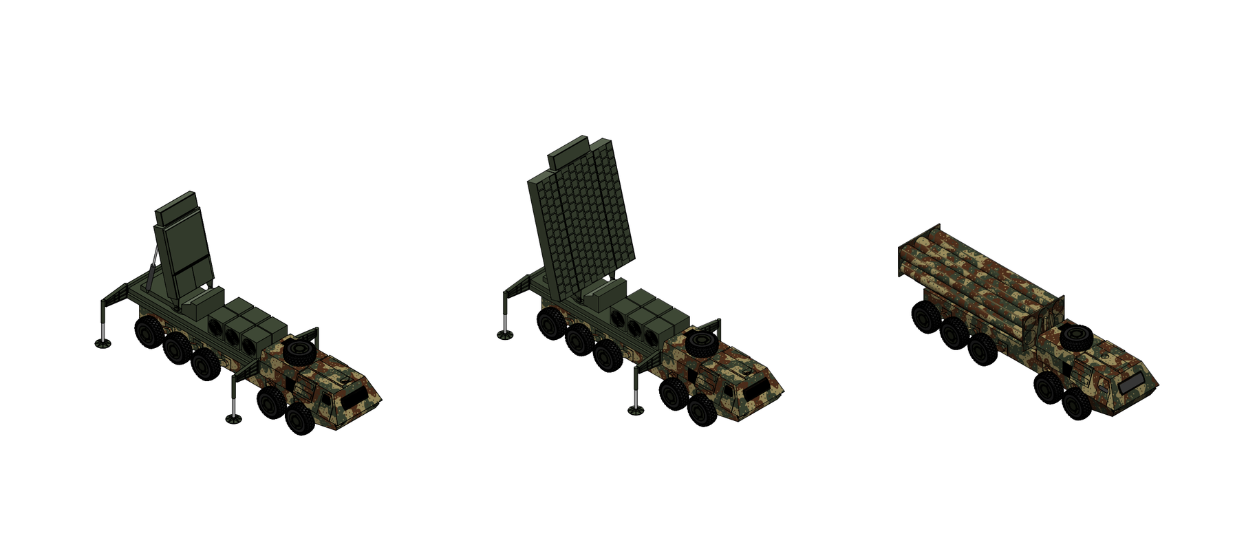
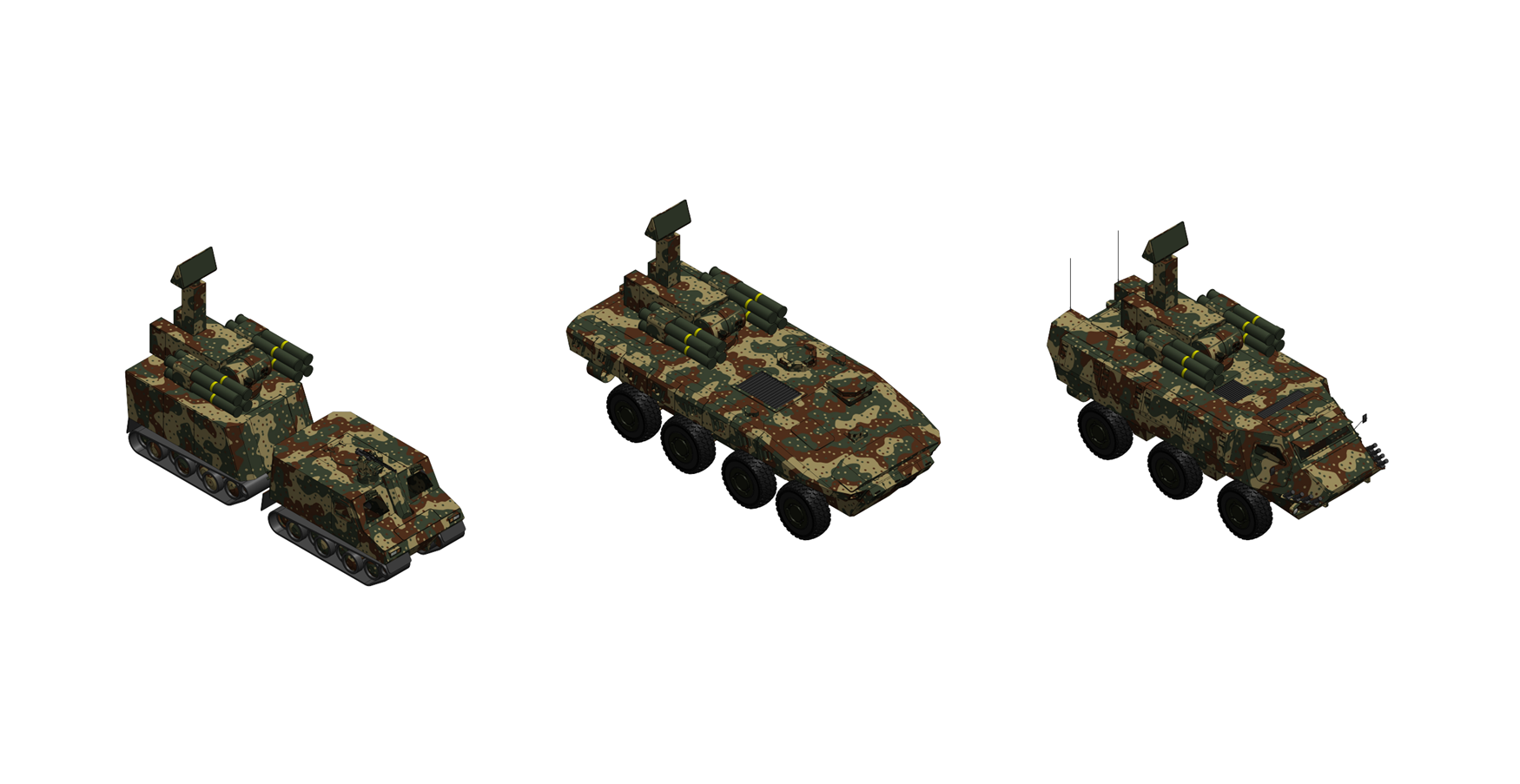
RBS 77 Extended Range Aerospace Defense System
System Overview:
The RBS 77 a rapidly deployable, mobile anti-ballistic missile and anti-hypersonic defense system designed by SDI Missile & Fire Control Systems. The RBS 77 system is designed to protect corps to field army units, military facilities, and civilian infrastructure from medium to intercontinental range ballistic missiles, hypersonic glide vehicles, hypersonic cruise missiles, maneuvering reentry vehicles by intercepting them in their terminal phase with hit-to-kill interceptors. A full RBS 77 ERADS Battery consists of eight TELs with six interceptors each, a trailer mounted X band extended long range acquisition and tracking radar which can track and discriminate incoming missiles and update tracking information for launched interceptors, and a fire control and communications vehicle which controls battery operation and which can communicate with other air defense sensors and systems to allow the RBS 77 system to be seamlessly integrated into a larger integrated air-defense network. The entire RBS 77 system is system is road mobile and can be transported by either ship, rail, or strategics airlifter aircraft in order to allow the entire system to be rapidly deployed around the globe where needed.
Rb 77 interceptor
- Weight: 2,000 kg
- Length: 7.0 m
- Diameter: 0.60 m
- Propulsion: Two-stage solid fuel rocket
- Operational Range: 1,000 km
- Intercept Altitude: 20-500 km
- Speed: 5.5 km/s (Mach 18)
- Warhead: none- KE hit to kill
- Guidance: dual-band infrared FPA
- Steering: Thrust-vectoring, solid DACS
- Launcher: Trailer based launcher with six canisters
The Rb 77 is a anti-ballistic missile interceptor designed to provide hit-to-kill terminal phase intercept of intercontinental ballistic missile (ICBM) and submarine-launched ballistic missile (SLBM) reentry vehicles, maneuvering reentry vehicles (MaRVs), and hypersonic glide vehicles (HGVs). The Rb 77 interceptor consists of a two-stage solid-fuel rocket booster and an endo/exo-atmospheric kill vehicle. The two booster stages employ graphite filament wound epoxy casings with 3-D carbon-carbon nozzles and employs a high performance HNF/AL/GAP composite propellant consisting of 60% HNF (Hydrazinium nitroformate) oxidizer, 20% Aluminum fuel, and 20% GAP (Glycidyl azide polymer) energetic binder. The first stage weighs 1,300 kilograms, has a specific impulse of 270 seconds, and burns for six seconds, accelerating the interceptor to a first stage burnout velocity of 2.4 km/s where the second stage separates and ignites. The first stage employs an electromechanical actuator (EMA) based gimballed nozzle with +/- 7.5° gimbal angle which is used for first-stage thrust vector control. The second stage weighs 450 kilograms, has a specific impulse of 290 seconds, and features a dual-pulse motor with two 4.5 second burns and provides additional acceleration and divert capability for the kill vehicle. The second stage features a thrust vectoring nozzle with a +/- 7.5° gimbal angle and features an integral warm-gas/cold-gas attitude control system (ACS) built into the aft end of the second stage motor which combines a cold-gas system (CGS) using compressed nitrogen thrusters and and warm-gas system (WGS) using solid-propellant gas generators and nozzles which provide roll, pitch, and yaw control while the second stage motor is firing or while the stage is coasting in between motor pulses. The interceptor's endo/exo-atmospheric kill vehicle weighs approximately 75 kg and employs a solid-propellant divert and attitude control system (DACS) for maneuvering. The kill vehicle DACS employs a total of 10 thrusters with variable-area pintle nozzles which allow each thruster to be throttled from 0-100% of maximum thrust for precise in-flight control. The 10 DACs thrusters provide roll, pitch, and yaw control during the terminal phase of intercepts and provide the kill vehicle with over 2.0 kilometers per second of divert delta-V with the ability to maneuver at up to 100 g.
The kill vehicle employs a dual-band imaging infrared (IIR) seeker which is used to provide endo and exo-atmopsheric target discrimination and tracking capability. The seeker uses a radiation hardened 512 x 512 pixel dual-band (MWIR and LWIR) digital-pixel focal plane array (FPA) with a 48 by 48° overall field of view mounted to a 2-axis stabilized AlBeMet alloy optical telescope assembly with selectable wide and narrow field-of view (WFOV and NFOV) modes which are selected in-flight based on whether the intercept is endo or exo-atmospheric. The optical assembly employs active line-of-sight (LOS) stabilization using the 2-axis stabilized telescope and a 6-axis laser-ring gyro IMU to provide sub-pixel image stabilization capability while the kill vehicle maneuvers at up to 100 g. Seeker acquisition range against a typical ICBM RV varies from 40 kilometers for endo-atmopsheric intercepts to over 300 kilometers for exo-atmospheric intercepts. The measurements from the seeker are combined with body orientation measurements from the 6-axis laser-ring gyro IMU based altitude reference system (ARS) built into the kill vehicle which when combined with the DACS thruster system steers the kill vehicle onto the correct interception trajectory after it has detected its target. The seeker window is mounted off-axis to the kill vehicle line of sight and employs a diamond/silicon optical window actively cooled with cold nitrogen gas pumped through internal micro-cooling channels for endo-atmospheric intercepts. The cooling system is designed to allow the infrared window to survive exposure to extreme hypersonic heating and also to provide minimal flow interference so that the infrared seeker can effectively acquire its target. For exo-atmospheric intercepts the seeker window is ejected with non-explosive actuators in order to remove residual heating effects and improve seeker sensitivity. The kill vehicle and interceptor have three selectable guidance modes depending on whether launch commit and target intercept happen in the endo or exo-atmospheric phases of flight including exo-commit/endo-intercept, endo-commit/endo-intercept, and exo-commit/exo-intercept:
Exo-commit/endo-intercept: In this mode a mid-course sensor tracks the target vehicle or target cluster in its midcourse phase while it is still travelling through the exoatmosphere and queues the interceptor to launch where the interceptor then launches and intercepts the target as it enters the upper endoatmosphere. After launch the first stage burns and is discarded where depending on the intercept range the second stage is either immediately ignited (for shorter range intercepts) or the interceptor coasts before igniting the second stage (for longer ranged intercepts). After the first pulse of the second stage burns out the interceptor coasts towards the target where the second stage warm-gas/cold-gas attitude control system is used to steer the vehicle towards the desired intercept point. When the interceptor closes to within seeker range the shroud over the kill vehicle seeker is jettisoned and the kill vehicle's dual-band infrared seeker begins a wide field-of-view (WFOV) sweep of the target area. The dual-band seeker is used to discriminate the warhead from decoys in the target cluster. When the seeker has locked onto the desired target the second pulse of the second stage is ignited and the kill vehicle's solid-propellant DACS thrusters are used to steer and accelerate the kill vehicle towards the target. After second pulse burnout the kill vehicle separates from the second stage and uses its DACS thrusters to perform the final steering and corrective maneuvers before hitting the target.
Endo-commit/endo-intercept: This mode is similar to exo-commit/endo-intercept except the interceptor is launched while the target is being tracked as it re-enters the atmosphere by a terminal sensor with the target intercept happening in the lower atmosphere. In this mode there is no coast between first and second stage motor burns or between the second stage pulses with kill-vehicle shroud jettison and kill-vehicle seeker target acquisition happening during first and second stage motor burn. After second stage burn the kill vehicle separates and the kill vehicle DACS for endgame maneuvering before impact with the target.
Exo-commit/exo-intercept: In this mode target tracking, discrimination, and commit and intercept happen while the target is travelling through the exo-atmosphere in its midcourse phase. Flyout and intercept are similar to exo-commit/endo-intercept mode except the coast between first stage burnout and second stage ignition is typically much longer. In this mode target discrimination is performed by the midcourse sensor with the interceptor correlating its seeker scene in NFOV mode with that of the midcourse sensor for terminal target acquisition and homing. This mode also lets the interceptor act as an ASAT (anti-satellite) missile with the capability to intercept satellite targets in low-earth orbit.
FMG 3300 Extended Range Acquisition and Tracking RadarThe FMG 3300 is an advanced X-band AESA radar designed for the RBS 77 system. The FMG 3300 performs long-range search and detection of ballistic missiles and hypersonic weapons, target discrimination to distinguish warheads from decoys and debris, and precision tracking and fire-control-quality state estimation for midcourse guidance of Rb 77 interceptors.The FMG 3300 The radar uses a trailer-mounted, single-faced 9.2 m2 wideband antenna with a total of 81,000 gallium-nitride (GaN) transmit/receive modules with a peak radiated power of approximately 1.2 megawatts and an average power of approximately 180 kilowatts. The FMG 3300’s antenna is a planar, direct-radiating AESA with each radiating element driven by its own dedicated digital transmit/receive channel with independent phase and amplitude control. The radiating aperture is approximately 3.70 meters wide and 2.5 meters tall, with a total illuminated area of approximately 9.25 square meters. The array employs over 81,000 GaN-on-diamond T/R modules arranged as quad-channel tile modules that integrate four T/R channels into a single compact package, allowing finer element spacing. The quad-channel tiles each contain four independent T/R channels sharing a common housing, DC power conditioning, control interface, and thermal baseplate. Each radiating element is a dual-polarized stacked-patch microstrip antenna, fabricated on a multilayer printed-circuit-board (PCB) substrate. Each element has two orthogonal feed ports (horizontal and vertical polarization), both connected to the T/R module, enabling the radar to transmit and receive in any combination of H, V, or simultaneous dual-polarization. The T/R modules are attached to a copper-molybdenum (CuMo) alloy heat spreader, which in turn is pressed against the liquid-cooled cold plate on the antenna’s backplane. This thermal path maintains the GaN junction temperature below 175° C under all operating conditions. The antenna is enclosed in a rigid composite radome that protects the aperture from weather, debris, and handling damage during transport. The radome is a multi-layer sandwich structure comprising an outer skin of woven quartz fabric in a cyanate-ester resin matrix, a syntactic-foam core, and an inner skin of Kevlar fabric in epoxy resin. The quartz outer skin provides low dielectric loss at X-band frequencies (loss tangent less than 0.001), while the Kevlar inner skin provides impact resistance and structural stiffness. The foam core’s thickness is tuned to provide a half-wave impedance match at the center frequency, minimizing reflection loss across the operating band to less than 0.3 dB. The radome’s outer surface is coated with a hydrophobic paint that sheds rain and prevents ice accumulation. For arctic operations, embedded resistive heating elements in the quartz skin can be activated to prevent ice formation, consuming approximately 5 kW of electrical power. The radome is attached to the antenna frame with quick-release latches that allow it to be removed for maintenance access to the subarray panels and T/R modules within approximately 30 minutes.
- Weight: 35,000 kg
- Length: 13.0 m
- Height: 3.6 m
- Frequency: 8.5-10.5 GHz (X-band)
- Peak Power: 1.2 MW
- Average Power: 180 kW
- Instrumented Range: 3,000 km
- Tracking Range (1m2 RCS ballistic missile): 2,000 km
- Tracking Range (0.01 m² HGV): 600 km
- Tracking Accuracy (1m2 RCS ballistic missile): < 5 m range, < 50 µrad angle at 1,000 km
- Azimuth: 120°(±60°)
- Elevation: 0° - 90°
- Target Capacity: 1,000 simultaneous
The FMG 3300 cooling system is a closed-loop liquid cooling system using polyalphaolefin (PAO) synthetic oil as the working fluid. The coolant is pumped at approximately 500 liters per minute through a manifold that distributes it to individual cold plates behind each subarray panel. The cold plates are brazed aluminum structures with micro-channel passages that maximize heat-transfer surface area while minimizing flow resistance. The heated coolant is returned to the trailer-mounted chiller unit, which uses a vapor-compression refrigeration cycle (R-410A refrigerant) to reject the heat to ambient air through a set of fan-cooled condenser coils. The chiller unit has a rated capacity of 400 kW, providing approximately 33 percent margin over the steady-state array heat load of approximately 300 kW at typical duty cycles (the 600 kW figure is the peak heat load at maximum duty cycle, which is sustained only during intense engagement scenarios). The chiller comprises two independent refrigerant circuits, each capable of 200 kW, providing redundancy: if one circuit fails, the radar can continue operating at reduced duty cycle (approximately 50 percent) without exceeding thermal limits. The electronics shelter’s additional 80 kW heat load is managed by a separate forced-air HVAC unit within the shelter, independent of the array cooling system.
The FMG 3300 radar's 1.0 GHz instantaneous bandwidth enables higher range resolution for target discrimination with the radar having the ability to generate high-range-resolution profiles (HRRPs) of detected objects, resolving individual scattering centers along the target’s range axis with a resolution of approximately 15 centimeters, sufficient to distinguish between RVs, heavy decoys, and lightweight balloon decoys based on their range-extent profiles. The radar also measures micro-Doppler signatures which provide additional discrimination cues. In high-PRF track mode, the radar transmits a train of coherent pulses and processes the returns through a Doppler filter bank, implemented as an FFT in the GPU processor. The radar's velocity resolution is approximately 0.015 m/s, enabling the radar to detect and measure micro-Doppler signatures caused by target spin, tumble, nutation, or structural vibration with extreme sensitivity. The onboard radar discrimination capability complements the kill vehicle’s seeker-based discrimination, providing a layered discrimination architecture that improves the probability of directing interceptors at real warheads. For hypersonic targets, the radar’s track-while-scan mode maintains continuous trajectory estimation even as the target maneuvers. The radar's track accuracy (less than 5 meters in range and less than 0.05° in angle at 1,000 km) provides the precision fire-control data needed to support the Rb 77 interceptor’s energy-management guidance law, which requires frequent updates of the target’s position, velocity, and acceleration vector. The radar can track more than 1,000 objects simultaneously, supporting the multi-target environments created by MIRV deployments or coordinated hypersonic salvos. The FMG 3300 processing engine is a cluster of eight ruggedized GPU compute nodes, each containing a high-performance GPU with approximately 50 TFLOPS of single-precision compute throughput, a host processor, high-bandwidth memory (HBM3, approximately 128 GB per node), and high-speed network interfaces. The nodes are interconnected by a low-latency fabric (<400 Gbps per link) that enables data sharing between nodes with microsecond latency. Two nodes are dedicated to digital beamforming and pulse compression, two nodes perform Doppler processing, CFAR detection, and monopulse angle estimation, one node runs the track processor (IMM Kalman filter, track management, state prediction), one node runs the discrimination algorithms (HRRP, ISAR, micro-Doppler, polarimetric analysis, and AI classifier), one node manages the adaptive resource scheduler, waveform generator control, and ECCM algorithms, and one node provides N+1 redundancy (its workload is redistributed across the remaining seven nodes in the event of a node failure). The nodes run a real-time operating system with deterministic scheduling that guarantees the hard-real-time latency requirements of the track and fire-control processing loops. The FMG 3300's ECCM functions includes adaptive digital nulling (ADN) which digitally forms nulls in the receive beampattern on jammer bearings while maintaining main-beam sensitivity, suppressing stand-off and escort jammers without degrading target detection with up to 12 simultaneous nulls, sidelobe blanking (SLB) with auxiliary widebeam antennas thar detects signals received through sidelobes and blanks those returns, rejecting sidelobe jamming and terrain clutter entering through the radar sidelobes, sidelobe cancellation (SLC) that subtracts sidelobe interference from the main beam to eliminate residual sidelobe jamming not fully suppressed by ADN and SLB, pulse-to-pulse and burst-to-burst frequency hopping across the full 2.0 GHz tunable bandwidth to defeats spot-frequency jammers, pseudo-random pulse compression code changing on a pulse-to-pulse basis with multiple simultaneous waveforms on different frequencies to defeat DRFM jamming, adaptive power management with transmit power scaled dynamically per beam position based on threat and jamming environment that can concentrates power on jammed sectors while reducing emissions in unjammed sectors, and AI-driven real-time assessment of the electromagnetic environment with automatic ECCM mode selection and parameter optimization to adapts to evolving jamming threats without operator intervention.
The FMG 3300 radar system elements include the phased array antenna, the electronic equipment unit, a 1.5 MW prime power unit, a cooling equipment unit which provides cooling for the antenna array, and an operator control unit which contains operator consoles for operations, maintenance and communications monitoring. The FMG 3300 is transported in two T 44 loads. The first load carries the antenna unit and its turntable pedestal on a specialized semi-trailer. The second load carries the electronics shelter (containing the radar processor, signal generator, waveform controller, and operator interface), the 1.5 MW diesel generator set, and the liquid cooling system’s chiller unit, each on separate trailers towed by HTTS prime movers. At the emplacement site, the antenna trailer is positioned and leveled, the antenna is erected from its horizontal transport position to its near-vertical operating position using integral hydraulic actuators, and cables are connected to the electronics shelter and generator. The entire radar emplacement process takes approximately 45 minutes from arrival to first radiation, with an additional 15 minutes for automated self-test and boresight calibration. Teardown is accomplished in approximately 30 minutes.