NATION

PASSWORD

SDI Aircraft Catalog [DO NOT POST]

A meeting place where national storefronts can tout their wares and discuss trade. [In character]
User avatar
The Technocratic Syndicalists
Minister
 
Posts: 2347
Founded: May 27, 2015
Inoffensive Centrist Democracy

SDI Aircraft Catalog [DO NOT POST]

Postby The Technocratic Syndicalists » Fri Apr 08, 2016 1:06 pm

Image


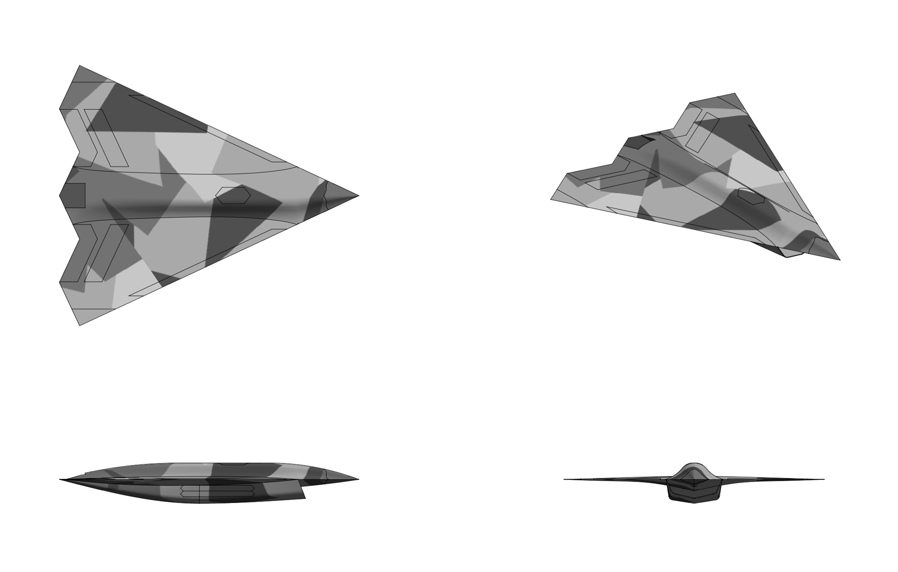
AEJ 36 Seraph

General Characteristics:
  • Role: Air Superiority Fighter
  • Crew: 1
  • Length: 21.0 m
  • Wingspan: 15.0 m
  • Height: 3.8 m
  • Wing area: 95 m2
  • Empty weight: 16,800 kg
  • Loaded weight: 29,100 kg
  • Fuel weight: 10,800 kg
  • Max takeoff weight: 38,700 kg
  • Powerplant: 2x SDI RM220 adaptive cycle afterburning turbofans, 205 kN each
Performance:
  • Maximum speed:
    • High altitude: Mach 2.9
    • Supercruise: Mach 2.2
  • Combat radius:
      1,200 km (Mach 2.2 @ 20,000 meters)
      2,000 km (Mach 0.85 @ 12,000 meters)
  • Ferry range: 5,600 km
  • Service ceiling: 22,700 m
  • Rate of climb: 470 m/s
  • Wing loading: 285 kg/m2
  • Thrust/weight: 1.44
  • Maximum g-loading: +9.0/-3.0 g
Armament:
Avionics:
  • SDI FMG 396 "Fenrir" X band AESA radar
  • SDI EOS 600 Advanced Infrared Search & Track System
  • SDI EOS 800 Multispectral Distributed Aperture System
  • SDI FMS 266 "Hammerhead" Electronic Warfare system
  • SDI FG 292 CNI system


Overview:
The AEJ 36 Seraph is an advanced, sixth generation, single seat, twin engine, all weather, stealth tactical fighter aircraft designed as a long ranged air-to-air combat aircraft with added versatility as a reconnaissance, electronic warfare, and strike platform.


Airframe & Construction:
Designed to both minimize radar cross section while maximizing supersonic aerodynamics and maneuverability the design of the Seraph is fairly unconventional with large, diamond shaped wings, highly angled all moving V-tail, and a highly area ruled fuselage designed to minimize transonic drag rise. The Seraph is intended to be highly maneuverable at both subsonic and supersonic speeds with an extremely high thrust to weight ratio, low wing loading, a high maximum angle-of-attack, high instantaneous turn rate, and an inherently designed relaxed static stability. Both the wing and V-tail of the Seraph use supercritical airfoils designed to have favorable lift, stall, and pitching moment characteristics at high mach numbers. The clipped diamond wings have an aspect ratio of 2.0, the similarly clipped diamond V-tail an aspect ratio of 2.5, with both having a leading and trailing edges having a sweep of 45 degrees. The aggressively chined forward fuselage section, in addition to having various radar very-low-observability benefits, generates large amounts of vortex lift at supersonic speeds which offsets the rearward shift of the aerodynamic center as the aircraft goes supersonic. The aircraft's relatively high L/D ratio at both subsonic and supersonic speeds due to its unconventional blended wing-body shape also allows for efficient cruise performance at both subsonic speeds and in supercruise. The aircraft's structure uses a semi-monocoque design constructed almost entirely of composites including a combination of forged and machined titanium metal matrix composites (MMCs) which make up approximately 50% of the structural weight and graphite-polyiamide and graphite-epoxy polymer composites (PMCs) formed using vacuum assisted resin transfer molding which represent 25% of the aircraft's weight. The use of significant amount of composites in the airframe reduces weight, improves airframe heat resistance for sustained supersonic flight, and reduces the aircraft's radar and infrared signature while also enabling the Seraph to be less maintenance intensive than previous generations of aircraft. Traditional aircraft materials such as aluminum make up only approximately 15% of the aircraft's weight while the remaining 10% consists of other miscellaneous materials.

The internal structure of the Seraph is constructed primarily from SCS-8 silicon carbide fiber reinforced Ti-5Al-5Mo-5V-3Cr (Ti-5-5-5-3) titanium metal matrix composite (MMC) structures. Compared to conventional titanium alloys the titanium metal matrix composite exhibits superior specific strength, specific stiffness, fracture toughness, wear resistance, creep and oxidation resistance which results in reduced airframe weight, superior resistance to ballistic damage, increased airframe durability and heat tolerance, and reduced maintenance requirements. The fuselage is constructed from eight titanium metal matrix longerons, five running on top of the wings and three along the bottom, which run from the front of the cockpit where they sweep either upward or downward and thicken at the intake and then run back all the way to the middle of the ruddervators. The fuselage is then divided longitudinally by nine titanium metal matrix bulkheads made from monolithic forgings which are directly connected to the longerons to better distribute structural loads. The bulkheads located in the middle of the fuselage are also joined to the titanium MMC spars in the wings. The monolithic forgings used for the fuselage and wing titanium MMC structures are additionally subject to Hot Isostatic Pressing (HIP) in order to eliminate any voids or gas pockets caused by the forging process before the components are joined together to create the airframe. The titanium MMC wing torsion-box spars are constructed from sinusoidal wave spars creating using super plastic forming and diffusion bonding (SPF/DB) which are connected to additional titanium MMC wing box frames. The titanium-MMC longerons, bulkheads, and wing spars are joined by a mixture of robotic laser welding using a pulsed Nd:YAG (neodymium-doped yttrium aluminium garnet) fiber-optic laser and robotic friction-stir welding under an inert argon atmosphere.

The skin panels, inlet ducts, landing gear and weapons bay doors, forward fuselage longerons, outer wing spars, and V-tail structure of the Seraph are constructed from laser aligned honeycomb sandwich panels several millimeters thick made from a polymer matrix composite consisting of a 3D weave of multi-walled carbon nanotubes (MWCNT) reinforced carbon fibers embedded into a high temperature polymer matrix. The matrix material used is a radar transparent polyimide resin which has a service temperature in excess of 400° C. The Seraph's weapons bay doors, empennage ribs and spars, and rear wing ribs and spars are constructed out of the same style composite but with an epoxy matrix replacing the polyimide for applications where the high service temperature of the polyimide matrix are unnecessary.


Vehicle Management System & Flight Control Surfaces:
Vehicle Management System (VMS): The Seraph's vehicle management system (VMS) is a quadruple redundant fully digital fly-by-wire control system responsible for controlling the aircraft in flight. The core of the VMS system are four vehicle management computers (VMCs) which interface using fiber-optic cables to the aircraft's control actuators, engines, cockpit controls, air data system, fuel system, and inertial navigation systems. The sensor subsystem of the VMS includes four air data computers (ADCs) and a low observable pneumatic air data system (LOPADS) which consists of four flush mounted pitot tubes located above the radome in front of the cockpit and four flush mounted static ports, two on each side of the fuselage, located aft of the radome above and below the forward fuselage chine and provides Mach, altitude, airspeed, angle-of-attack, and sideslip data to the VMS. The VMS system also includes a fuel-control system which can pump fuel from forward fuel tanks to aft ones and vice versa to allow the aircraft to change its CG and stability margin in flight.

Control surfaces: The control surfaces of the Seraph include twin all-moving V-tails, inboard and outboard variable camber flaperons (combined flaps and ailerons), and variable-camber leading edge flaps. The variable camber flaps and ailerons can be continuously deflected in flight to provide near-ideal wing camber for any flight condition and are smoothly blended into the wing to reduce both parasitic drag and the radar return of the control surfaces. The aircraft's control surfaces are controlled using a decoupled flight control architecture which the aircraft to maneuver in one plane without maneuvering in the other (such as turning without banking) and allows any of the aircraft's major control surfaces to provide any control surface function (roll, pitch, or yaw). Under normal flight conditions pitch is provided by deflecting the V-tails in opposite directions, yaw is provided by deflecting the V-tails in the same direction, and roll is provided by deflecting the wing ailerons in opposite directions. Yaw control can also be provided by differential thrust of the engines. The aircraft also features a virtual speedbrake capability achieved by deflecting the outboard flaperons up and deflecting the inboard flaperon and leading edge flaps down. The control surfaces of the Seraph are actuated using a series of self-contained electrohydrostatic actuators powered by the aircraft's electrical system and connected to the aircraft's vehicle management computers through fiber-optic cabling and replace the hydraulic actuators and pumps of a traditional fly-by-wire control system with self-contained actuators that convert the electrical power into localized hydraulic power for flight control purposes. Each control surface of the Seraph including left and right V-tails, inboard and outboard trailing edge flaperons, and leading edge flaps is independently actuated using a series of EHA-VPVM (electro-hydrostatic actuator with variable pump displacement and variable motor speed) actuators which employ variable speed brushless DC permanent magnet motors to drive a variable displacement servopump which is connected to the two chambers of a hydraulic cylinder that is used to actuate the aircraft's control surfaces.

Self-Repairing Flight Control System (SRFCS): A Self-Repairing Flight Control System (SRFCS) is integrated into the aircraft's Vehicle Management System is designed to detect damage or failure in the V-tails, flaperons, and leading edge flaps. When the system detects damage or loss of a flight control surface or actuator the system then compensates by reconfiguring the remaining flight control surfaces and changing the control laws of the flight control software so that aircraft remains controllable and can be landed safely by the pilot. The SRFCS displays all damage to flight control actuators and surfaces to the pilot through the multifunction display in the cockpit which indicates to the pilot the extent of the damage and any flight speed or maneuverability limitations imposed by the damage. The SRFCS combined with the Seraph's decoupled flight control system and lifting body fuselage allow the aircraft to potentially lose an entire wing or one of its V-tails and still maintain controlled flight. In the event all the aircraft's control surfaces are destroyed or disabled the Seraph's Vehicle Management System can command increasing or decreasing engine thrust to pitch up or down (respectively) and differential engine thrust to turn, proving enough control to steer the aircraft to an airfield and perform a safe landing.


Propulsion:
  • Name: SDI RM220
  • Type: Adaptive Cycle Afterburning Turbofan
  • Length: 5,080 mm
  • Diameter: 1,170 mm
  • Dry Weight: 1,800 kg
  • Bypass Ratio: variable
  • Compressor: Two stage fan, core driven fan stage (CDFS), five stage high pressure compressor
  • Combustor: Pressure-gain combustor
  • Turbine: single stage HPT, counter rotating single stage LPT
  • Maximum Thrust: 159 kN (dry), 205 kN (with afterburner)
  • Overall Pressure ratio: 26:1
  • Turbine inlet temperature: 1,980 °C
  • Specific fuel consumption: 20 g/Kn-s (dry), 40 g/Kn-s (afterburning)
  • Thrust-to-Weight Ratio: 9.0:1 (dry), 11.6:1 (with afterburner)
The Seraph is powered by a pair of SDI RM220 afterburning turbofans which each deliver up to 205 kN of thrust will full afterburner. The RM220 engine employs adaptive cycle engine (ACE) technology which allows the engine to change its overall bypass ratio and fan pressure ratio through the use of adaptive geometry devices in flight. The core of the RM220 is a two-spool turbofan with a low pressure spool consisting of two stage fan and single stage low pressure turbine and a high pressure spool consisting of five stage high pressure compressor with core driven fan stage (CDFS) and a single stage high pressure turbine. The two stage fan employs a blisk construction with rotor and highly swept wide-chord blades constructed from carbon fiber reinforced polyamide with Ti-6Al-4V titanium alloy reinforcement along the leading edges. The five stage high pressure compressor employs integrally bladed rotors (IBTs) is constructed from Ti-48Al-2Cr-Nb gamma titanium-aluminide (TiAL) alloy which provides comparable or better temperature and creep performance compared to conventional nickel super alloys while having half the density. The first stage of the high pressure compressor is a core driven fan stage (CDFS) and employs extended blade tips that act the third stage of the two stage fan and supercharges the flow entering the engine's bypass flow streams. The combustor of the engine is a double-dome annular combustor with two toroidal primary combustion zones and employs a combustion liner constructed from 3D woven SiC/SiC ceramic matrix composite (CMC) consisting of silicon carbide (SiC) fibers woven into a chemical vapor infiltrated (CVI) SiC matrix and a rare earth monosilicate environmental barrier coating (EBC) for increased oxidation resistance at higher temperatures. The high pressure turbine employs a rotor and blades constructed from 3D woven SiC/SiC with environmental barrier coating with internal blade cooling channels through which high pressure bleed from the compressor flows through after first being cooled by a heat exchanger located in the engine's triple-bypass FLADE duct. The internal cooling channels are combined with additional film cooling on the surface of he high pressure turbine blades to keep the Sic/Sic composite within it normal operating temperature limits. The counter-rotating low pressure turbine also employs 3D woven SiC/SiC construction but unlike the high pressure stage is not cooled.

The variable cycle features of the RM220 engine include the ability to alter fan pressure ratio through the use of a split variable-geometry fan with twin bypass streams and bypass ratio control altered through the use of a second airstream controlled using Variable Area Bypass Injectors (VABIs) that can either be used to provide additional air flow for higher fuel and propulsive efficiency or can be used to provide additional thrust by increasing core flow and and airflow for cooling the high temperature parts of the engine. The adaptive cycle RM220 adds an additional third bypass stream controlled by a row of variable inlet guide vanes and a single compression stage made by extending one row of main fan blades into the third bypass stream, a fan on blade or FLADE arrangement. Additionally the RM220 includes a core driven fan stage (driven by the high pressure turbine) which provides a boost in pressure to both the core stage and inner bypass flow streams, increasing the engine's overall pressure ratio. The split fan and Variable Area Bypass Injectors allow the RM220 to independently control both the high and low pressure rotor speeds to allow for higher airflow at subsonic speeds and higher specific thrust at supersonic speeds than would be possible with a conventional fixed-geometry mixed flow turbofan. To ensure efficient variable-cycle operation the RM220 also uses a variable-area low-pressure turbine nozzle (VATN) which allows the engine to operate with additional fan flow at low specific thrust settings to reduce engine noise during takeoff. The RM220 has three sets of VABIs. The first VABI is mounted aft of the frontal fan and allows the outer bypass duct to be open to operate in single or double bypass mode or closed to operate in zero-bypass mode. The second VABI is mounted aft of the rear split fan and permits fan operation in either single or double bypass modes. In single bypass mode the valve is closed so that the rear fan exhausts into the high-pressure compressor and into the inner bypass duct with the rear modulating VABI in the open position. When the second VABI valve is opened the engine operates in double-bypass mode where the rear fan air is discharged into both the inner and outer bypass ducts. The rear or exhaust VABI operates a a variable area bypass nozzle which injects the secondary bypass flow into the core stream behind the low pressure turbine into the afterburner or bypasses around the afterburner and inject the bypass into the variable-area low-pressure turbine nozzle (VATN) in either single or double bypass mode. The VABIs, which combined weigh only several kilograms, are individually actuated by lightweight Ti–Ni–Zr high-temperature shape memory alloy (HTSMA) actuators. The split-fan of the RM220 is additionally fitted with Variable Inlet Guide Vanes (VIGVs) which provide efficient thrust modulation across the engine's thrust envelope. For subsonic cruise the VIGV is used to reduce the flow entering the high pressure compressor with the rest bypassed to eliminate excessive spillage drag at low speeds and partial throttle settings. The VIGV are mounted in front of the high-pressure compressor and consists of stationary leading-edge vanes and variable trailing-edge flaps actuated with Ti–Ni–Zr high-temperature shape memory alloy (HTSMA) actuators that carry the mass flow rate of the engine as a function of engine cycle and freestream velocity. The RM220 has an additional set of Variable Inlet Guide Vanes which control the airflow into the third bypass stream (The FLADE duct) which bypasses boundary-layer flow around the core and injects it downwards of the turbine to cool the nozzle and reduce the infrared signature of the exhaust. The last ACE component, the variable-area low-pressure turbine nozzle (VATN), maintains engine efficiency at partial throttle settings by decreasing the nozzle area and thereby increasing the turbine inlet temperature to it's full-throttle state. Being able to operate in partial throttle settings is useful for low-speed loiter and for takeoff where the lower exhaust temperature due to the extra bypass air reduces the jet noise of the engine

The RM220 includes a fully digital FADEC (Full-Authority Digital Engine Control) system which includes a digital electronic control unit (DECU), ignition system, fuel control system, air flow control system (AFCS), adaptive cycle control system (ACCS), and various sensors. The FADEC system controls engine and afterburner fuel flow, variable inlet guide vane (VIGV) position, variable area bypass injector (VABI) position, variable-area turbine nozzle (VATN) position, and exhaust nozzle area as a function of throttle position and engine temperature and pressure sensor input in order to optimize the engine's thrust and fuel consumption over the aircraft's operating range while staying within the engines temperature and pressure limits. An integrated engine mode (IEM) in the FADEC also provides airspeed hold capability, providing a content acceleration or deceleration in response for a given forward or aft throttle displacement and an airspeed hold with the throttle placed into a center detent position. The core component of the FADEC system is the digital electronic control unit (DECU), a fuel-cooled computer system attached to the underside of the engine casing through vibration isolating mounts. The DECU contains two microprocessors independently connected through high speed serial links to the vehicle management system (VMS) and all engine actuators and sensors.

The Seraph uses a pair of of ASIs (Advanced Supersonic Inlets) on either side of the fuselage. The ASI is a divertless, three dimensional mixed compression inlets featuring a triangular shape designed to both maximize supersonic efficiency and minimize incident radar reflections. The ASI is similar in design to traditional divertless supersonic inlet (DSI) designs, with a contoured bump that diverts low-energy boundary layer air, but unlike the DSI which features external compression the ASI is a mixed-compression design with both external and internal supersonic compression. As mixed-compression inlets feature less drag and improved efficiency past supersonic mach numbers of 2.0 or higher the ASI, with a design mach number of approximately 2.5, allows for highly efficiency supersonic cruise at high mach numbers past the operating envelope of a simpler external compression diverterless inlet. In addition to the ASI's the aircraft has a a pair of auxiliary inlets located above the wing on either side of the fuselage. The inlet ducts are an S shaped and feature a spill door behind the engine face which vents above the wing. The exhausts are 2-D single expansion ramp nozzles (SERN) blended into the upper rear fuselage to reduce their radar signature and minimize the IR signature of the exhaust. The nozzle has a variable upper flap and a fixed lower half and is non-thrust vectoring. The nozzle troughs are made superplastic formed and diffusion bonded (SPF/DB) Ti-48Al-2Cr-Nb gamma titanium-aluminide (TiAL) alloy cooled using high pressure bypass air from the FLADE duct of each engine.


Power & Thermal Management:
The Adaptive Power and Thermal Management System (APTMS) of the Seraph combines the functions of an auxiliary power unit (APU), emergency power unit (EPU), environmental control system (ECS), and thermal management system (TMS), and electrical power generation system (EPGS) in one integrated, adaptive system which actively manages the aircraft's electrical power generation and cooling needs in real time across various flight conditions. The thermal management system (TMS) component of the APTMS employs a vapor cycle system (VCS) which handles the majority of the waste heat from the aircraft' avionics and other systems. The VCS employs a series of cooled cooling air heat exchanger (CCHX) modules located in the FLADE duct of each RM220 engine which combined provide several megawatts of cooling capacity. Cooled air from both the the FLADE duct heat exchanger modules and from a fuel to air heat exchanger is incorporated into the vapor cycle system condenser and is used for cooling the working fluid in the refrigeration loop of the vapor cycle system with waste heat from the VCS transferred into the aircraft's internal fuel through a heat exchanger using polyalphaolefin (PAO) as the working fluid. Cooled working fluid from the VCS is used to cool the avionics and other electrical systems before being passed back into the VCS condenser, itself the heat-exchanger connected to the aircraft's fuel system. At subsonic speeds an interfuel tank recirculation loop is used to recirculate fuel between the colder wing tanks and the hotter internal fuel tanks which are used as aheat sink by the VCS system, the loop being closed off at supersonic speeds to allow the wing tanks to act as heat sink to absorb the heating loads on the wings during sustained supersonic flight.

Replacing both the APU and the ECS in the aircraft's adaptive power and thermal management system is an Integrated Power Turbomachine (IPTM), a miniature twin-spool turboshaft engine connected to a high-reactance permanent magnet machine (HRPMM) motor/generator unit which is initially used to start the IPTM and then used to generate power after the IPTM transitions to self-sustaining operation. Electrical power from the IPTM is then used to power the starter/generator units attached to each main engine in order to start both main engines. After starting both main engines the IPTMs transitions into cooling mode where the fuel flow to the IPTM is cut and the IPTM's compressor inlet is closed where thereafter electrical power from the main engine generators is used to power the IPTM's in closed-loop mode. Back EMF from the aircraft's hydroelectric control systems can also be used to drive the IPTM in order to temporarily offload the main engine generators. In closed loop mode air from the IPTM compressor is first passed through microchannel titanium heat exchangers located in the FLADE duct of each RM220 engine and then through an air-fuel heat exchanger before then being passed back into the IPTM where it is then further cooled and expanded in the IPTM's cooling turbine. Cool air from the IPTM is then used to pressurize the cockpit and to provide cooling for both the cabin air and for the aircraft's fuel tanks. In emergency power mode the IPTM functions as an APU, the compressor inlet is opened and air is compressed by the compressor, combustive, and then uses to drive the power turbine which produces electrical power for critical avionics and for re-starting the main engines. To increase the ruggedness and efficiency of the system the IPTM itself employs self-acting hydrodynamic foil bearings , eliminating the need for lubricated bearings and associated oil pumps and filters, and a Variable Area Turbine Nozzle (VATN) which when operated as a turbogenerator maximizes the specific fuel consumption of the IPTM across a broad variety of operating conditions.


Stealth:
The Seraph is designed to have an extremely low radar cross section across multiple bands through the combination of airframe shaping and advanced radar absorbing materials. The Seraph is designed with broadband, all-aspect stealth in mind and features a combination of shaping features and radar absorbing structures and materials designed to counter 0.1-1 GHz long-range surveillance radars, 1.0–3 GHz AWACS radars, and 10 GHz fighter radars illuminating the aircraft simultaneously and from multiple directions. The aircraft is shaped using smoothly blended external geometry with a continuously varying curvature designed to minimize surface currents and scatter radar waves that hit the aircraft across its entire aspect. The leading and trailing surfaces of the wings, intakes and V-tail are all aligned parallel to each other at a 45 degree angle which concentrates specular radar returns into thin, narrow spikes on either side of the aircraft that minimize the chance an incident radar will get a strong return signal. The Seraph also lacks leading edge extensions and instead uses vortex lift generating chines blended into the fuselage which eliminates presenting corner reflections or vertical sides to radars while eliminating circular radar returns from the fuselage. The aircraft's large V-tails are positioned to eliminate corner reflections with the fuselage and sized to eliminate resonance or Raleigh scattering effects at lower UHF or VHF radar frequencies. Weapons bay doors, landing gear doors, and other access panels of the aircraft feature a saw-tooth shape designed to eliminate radar returns from traveling waves across the surface of the aircraft. Gaps between panels and joints on the aircraft are sealed using a combination of flexible conductive form-in-place (CFIP) sealant, conductive bulb seals, and conductive tape which is placed around ready access panels and used to seal the gaps between the the wing and the control surfaces. Reduction of the radar signature from the aircraft's inlets is achieved through the use of diverterless inlets blended into the leasing edge of the aircraft which eliminate the radar reflections caused by a traditional boundary layer diverter or other inlet structures. The diverterless inlets combined with S-duct serpentine intakes also serves to prevent line-of-sight view of the engine's turbine blades from any exterior view. Further reduction of the aircraft's radar signature comes from a hybrid dielectric/magnetic fiber-mat radar absorbing material which is cured into the aircraft's honeycomb composite skin. The RAM consists of randomly oriented carbon fibers infused with multiwall carbon nanotubes coated with a magnetic FeNi nanopowder which are aligned and then cured into an thermoset exposy resin to form a fiber-mat panel which is cured into the aircraft's composite skin. The RAM is made in two layers, the first designed to reduce reflected radar waves by having a thickness intended to optimize internal reflections and a second, more electrically conductive layer with a higher density of CNTs infused into the carbon fibers which dissipates the remaining radar energy as heat and electrical energy. The impedance of the fiber-mat RAM is matched to air at its outer surface and creates essentially a black body absorber from the VHF through W radar bands (0.1 - 60 MHz). Arrangement of the CNTs in multiple orientations allows the RAM to simultaneously absorb incident radar waves from multiple radar source impinging at different incidence angles. The 3D weave is cured into the aircraft's skin panels using a vaccum assisted resin transfer molding process to create each of the individual layers of the RAM (two in total) which are embedded with the composite skin of the aircraft and act as an additional structural member of the skin in addition to functioning as a radar absorbing structure. The RAM does not cover the entire aircraft and is placed in areas where the radar signature can not be reduced through shaping methods such as the wing and tail leading and trailing edges, inside the engine inlet ducts, and on the sides and underside of the fuselage. With the combination of stealth shaping and advanced RAM the Seraph has a radar cross section of around -45 dBSM across the frontal arc, -30 dBSM from the sides, and -35 dBSM from the rear.

In addition to low radar observability the Seraph also features a variety of infrared signature management technologies. The carbon nanotube RAM coating on the aircraft also functions as a moderately effective infrared absorber due to the high infrared absorptivity of CNTs, reducing the aircraft's skin infrared signature in long-wave infrared wavelength (8–12 microns) by around half where the where the RAM is present. The 2D ejector nozzles of the aircraft also serve to reduce the infrared signature of the exhaust by promoting greater mixing of the hot exhaust with ambient air. The hot exhaust from the aircraft's engines is cooled using bypass air and additional secondary air inlets before exiting through exhaust trenches blended into the rear fuselage located between the twin V-tails. The exhaust trenches or tunnels are made of titanium-aluminum alloy coated with low-emissivity carbon/carbon (C/C) ceramic composite tiles and serve to shield direct view of the hot exhaust from the sides or from below the aircraft. To reduce the infrared signature of the airframe itself the fuel and bypass air streams are used as heatsinks for the avionics such as the radar and jamming system which by themselves generate a tremendous amount of heat when active. Further reduction of infrared signature is achieved by circulating fuel around the leading edges of the aircraft which also serves to reduce the heat buildup from sustained supersonic flight. The aircraft also features a series of deployable air scoops along the wings designed to provide cooling air to the engine and power and thermal management system and a set of air scoops located alongside the wing/fuselage junction to provide additional cooling air flow to the engine nacelles.


Avionics:
The Seraph employs an Integrated Avionics System (IAS) architecture which uses sensor fusion from all the the aircraft's sensors and from and off-board data sources in order to achieve long range detection, high confidence BVR identification, and highly accurate target tracking for BVR weapons employment and/or threat avoidance before the Seraph is detected by enemy sensors. The system's air tactical situation model generates target track files of all air objects in the environment which are continually and automatically updated without pilot intervention. Detected air targets receive increasingly higher tracking accuracies as they penetrate a series of tactical engagement boundaries surrounding the aircraft which include the initial track and target ID, the engage/avoid decision, Rb 100 launch envelope, threat missile launch envelope, and threat missile lethal envelope/no escape zone. The boundaries are designed to provide the pilot with sufficient time to make decisions to engage or avoid targets without having to manually manage the aircraft's sensors. Data from the aircraft's sensors including radar, IRST, and EW data is automatically fused and correlated into a single integrated track file for each air and surface object with autonomous sensor tasking which selects the appropriate sensors and sensor modes to support the tracking accuracy requirements of each engagement boundary. The integrated track files for each air object including their kinematic and ID estimates and engagement boundaries are also displayed on the cockpit's multifunction display.

SDI FMG 396 Fenrir X band AESA Radar: The primary sensor of the Seraph is the FMG 396 Fenrir, a long range, low probability of intercept (LPI), fully digital multifunction X band (8-12 GHz) AESA radar which includes forward and side looking radar arrays mounted in the nose of the aircraft. Components of the FMG 396 radar include the chined frequency-selective surface (FSS) composite radome, main AESA, side AESAs, common beam steering computer, power supply, and radar support electronics enclosure. The radar system supports multiple simultaneous operation modes including long range search, long range cued search, all aspect medium range velocity range search, multiple target track, missile datalink capability, automatic target recognition, target cluster breakout/raid assessment, and weather detection. The radar also supports air-to-ground modes including high resolution synthetic aperture radar (SAR) mapping and ground and maritime moving target tracking (GMTI/MMTI) along with electronic warfare modes including electronics support measures (ESM) receiver and electronic-attack (EA) capability. The main array of the FMG 396 employs 2,400 full-duplex, multi-channel, dual-polarized transmit and receive (T/R) modules which each employ a gallium nitride (GaN) on diamond monolithic microwave integrated circuit (MMIC) front end with a silicon germanium (SiGe) Bipolar CMOS (BiCMOS) core chip. The side cheek arrays are smaller than the main array and each employ 600 of the same T/R modules as the main array with a conformal antenna blended into the side of the forward fuselage. The FMG 396 is fully digitized and includes a digital beam former (DBF) and digital receiver/exciter (DREX) module for every antenna element which contains a field-programmable gate array (FPGA), analog-to-digital converter (ADC), and digital-to-analog converter (DAC) which enable a variety of adaptive and dynamic beam-forming techniques to increase beam-scanning accuracy and increase electronic countermeasures resistance. The ECCM functionality of the FMG 396 include randomized burst-to-burst and pulse-to-pulse frequency-hopping, staggered multiple-PRF operation, randomized multiple-beam scan patterns designed to confuse hostile radar warning receivers, sidelobe blanking (SLB) and tapered illumination functions which reduces sidelobe emissions, adaptive null-steering and null-forming techniques for cancelling out directional jamming, and active jammer tracking on both elevation and azimuth. Low probability of interception/detection (LPD/LPI) operation is facilitated by frequency-modulated continuous wave (FMCW) operation which adaptively reduces radar power to the minimum necessary level to continue tracking targets. Automatic target recognition (ATR) techniques supported by the FMG 396 system include high range resolution profile (HRRP), inverse synthetic aperture radar imaging (ISAR), and jet engine modulation (JEM). Peak power output of the FMG 396 is 48 kW and maximum detection range is 400 km for a 1m2 target and 130 km for a 0.01 1m2 target in single-target track (STT) mode. High resolution SAR imagery with <0.3 meter spotlight and <1 meter stripmap mode resolution can be generated by the radar system out to 300 kilometers using enhanced real-beam ground map mode with optional doppler-beam sharpening for additional resolution improvement. The cooling system required to support the radar's high peak power output is a two-phase hydrofluoroether (HFE) based dielectric fluid based system using vapor chamber cold plates connected to the antenna modules which dumps the heat from the radar systems into the aircraft's vapor cycle system (VCS).

SDI EOS 600 Advanced Infrared Search & Track System: Mounted in faceted low-RCS housing underneath the nose is an SDI EOS 60 Advanced Infrared Search & Track (AIRST) system, a step-stare infrared search and track system which consists of a two-axis stabilized mirror assembly, four-panel conformal optical window, and a high-magnification mercury cadmium telluride (HgCdTe) starring focal plane array (FPA) imaging infrared (IIR) sensor providing entirely passive long-ranged electro-optical search and track capability to supplement the active scan capability of the FMG 396 radar. The 1280 × 1024 pixel HgCdTe array used in the sensor operates in both the MWIR (3–5 µm) and LWIR (8–15 µm) wavelengths and uses a hybrid complementary metal-oxide semiconductor (CMOS) FPA architecture with telescope optics providing three step-wise field-of-views; 8°x 6.4° narrow field-of-view (NFOV), 16° x 12.8° medium field-of-view (MFOV), and 30° x 24° wide field-of-view (WFOV). The infrared sensor system is cooled to 180 degrees K using a six-stage thermoelectric peltier cooler and is mounted on a vibration isolated gimbal system which provides each sensor with +20°/- 45° degree elevation and +/- 75 azimuth scan coverage. The AIRST system supports both single and multiple-target tracking with track-while-scan (TWS) functions against up to 200 targets with < 0.25 mrad tracking accuracy and can also display infrared sensor feed at into the pilot's helmet mounted display or cockpit head-down display at a rate of up to 60 Hz to act as a FLIR for navigation or targeting purposes. Multi-Ship Infrared Search and Track (MSIRST) capability is also supported by the AIRST system which allows two or more Seraph aircraft to passively triangulate targets by sharing bearing and elevation data of target tracks from their AIRST systems using the aircraft's high speed tactical datalink enabling the generation of completely passive 3-D tracks of airborne targets. Maximum detection ranges for the AIRST are 130-200 kilometers depending on target type and aspect. Data from the AIRST can also be be sensor-fused in real time with radar data from the APG-96 to provide highly accurate and jam-resistant detection, tracking, and fire control capability to the Seraph's weapon suite.

SDI EOS 800 Multispectral Distributed Aperture System: the Seraph's EOS 80 Multispectral Distributed Aperture System (MDAS) consists of six 1280 × 1024 pixel mercury cadmium telluride (HgCdTe) starring focal plane array IR imagers similar to the ones used in the EOS 600 placed around the aircraft which provide 360 degree spherical situational awareness infrared search and track (SAIRST), missile approach warning (MAW), and 360 degree spherical day/night pilot vision. One sensor system is placed in the nose pointing forward, two in the nose pointing sideways, one aft of the cockpit pointing upwards, and two on the lower fuselage pointing downwards. The system allows for simultaneous 360 degree spherical tracking of air and surface targets, 360 degree spherical missile approach warning (MAW) capability, and 360 degree spherical pilot vision around the aircraft in all weather conditions. The MDAS is capable of simultaneously tracking enemy aircraft, surface and ground targets, surface to air, air to air, and ballistic missiles, can automatically cue appropriate missile countermeasures, and allows high off bore launching of missiles in any direction relative to the aircraft.

SDI FMS 260 "Hammerhead" Electronic Warfare System The FMS 266 "Hammerhead" electronic warfare system is a comprehensive offensive and defensive electronic warfare (EW) and electronic support measures (ESM) suite which combines passive radar warning receivers, countermeasures dispersal, and intelligent, adaptive phased array jamming functions. The combined radar warning receiver (RWR) and electronic support measures system (ESM) of the FMS 266 consists of 24 conformal load-bearing antenna structures (CLAS) blended into the carbon-fiber composite skin of the fuselage, wings, and tails of the aircraft. The antennas include 18 mid/high band antennas covering the 2-40 GHz frequency range and six low band antennas covering the 0.1–2 GHz frequency range which feed into a network of ultra-wide bandwidth digital receivers for signal processing of received radar signals and provides 360° spherical broadband, all aspect detection, identification, geolocation, and tracking of radar emissions in the 0.1-40 GHZ range with 40 GHz of instantaneous bandwidth combined with less than 1 degree RMS angle-of-arrival (AoA) precision through the use of dual-baseline interferometer and time-difference-of-arrival (TDOA) direction-finding techniques. The high cruise altitude of the aircraft allows the passive receiver system to detect and track line-of-sight RF emissions from ground and ship radars out to 600 kilometers (radar horizon limited) and RF emissions from airborne radars out to over 1,000 kilometers. The passive receiver system also supports bistatic over-the-horizon RF intercept capability allowing RF signals from ground based radars which reflect off aircraft, missiles, satellites, or other air or space borne objects to be detected and tracked by the system at ranges exceeding 2,000 kilometers. The EW subsystem employs resource sharing of common hardware components to perform the simultaneous search, detection, RF measurement, signal analysis, direction finding, identification, geolocation, and tracking of RF signals while simultaneously supporting active jamming of radar threats through the use of adaptive emitter tuning in ECM heavy environments. Functions supported by the FMS 266 passive radar receiver system include specific emitter identification and verification (SEI/SEV) and intentional modulation on pulse (IMOP) detection capability which provides signal detection and analysis and characterization of incident radar pulses in extremely heavy ECM environments. Precision location strike system (PLSS) capability is also supported by the system which allows up to three Seraph aircraft operating together to geolocate RF emissions in real time through the use of the aircraft's tactical data link. To precisely locate emitters PLSS functionality uses time-difference-of-arrival (TDOA) techniques to precisely geolocate threat emitters, direction-of-arrival (DOA) techniques to filter and identify specific threats, and distance measuring equipment (DME) techniques to precisely determine the aircraft's position with the respect to the emitters.

The offensive EW capability of the FMS 266 Hammerhead system includes 18 active ECM antennas, six low band transceiver antennas covering the 0.5–2 GHz frequency band, six mid-band transceiver antennas covering the 2–6 GHz frequency band, and six high-band transceiver antennas covering the 6–40 GHz frequency band located on the wingtips and leading and trailing edges of the aircraft's wings, and two receive-only broadband 8-arm spiral antennas located on the top and bottom of the fuselage covering the 0.5-40 GHZ frequency range. Each transceiver antenna employs GaN-on-diamond based active electronically scanned array (AESA) antenna technology with digital beam-forming and digital receiver/exciter units and provides 360 degree DRFM deception jamming of radar threats around the aircraft. Each antenna employs a frequency-selective surface (FSS) which consists of an organic honeycomb sandwich structure with embedded wideband end-fire phased arrays employing GaN-on-diamond T/R modules which are structurally integrated into the aircraft's skin panels, reducing drag and radar cross-section over conventional non-structurally embedded and external antenna. The FMS 266 is a fully cognitive and adaptive system; by using emissions data collected from the FMS 266s radar warning receiver the DRFM jammers can automatically adapt in real time to unknown waveform characteristics, dynamically synthesize countermeasures, and jam the waveform accordingly, allowing the system to effectively jam digitally programmable LPI frequency modulation continuous wave radars employing highly agile waveforms. The DRFM Jammers of the system also include false target generation capability which takes incoming radar signals and injects a variable delay line into the signal before transmitting it back to the receiver, allowing false targets to be generated and their range and speed varied to simulate a real aircraft. The false target generator system can generate up to 32 simultaneous false targets at ranges from less than 150 meters to over 675 kilometers from the aircraft with RCS of false targets varying from near-invisible stealth targets to large size blimps to spoof hostile radar systems. Jet engine modulation (JEM) and high resolution range profile (HRRP) returns for false targets can also be synthesized in order to confuse and spoof hostile radar automatic target recognition (ATR) techniques. To prevent the jammer output from blinding the aircraft's own communications system the FMS 266 includes an Interference Cancellation System (INCAS) located in the forward fuselage of the aircraft behind the radar which selectivity cancels out the jammer interference in the path of radiated signals. This is done by collecting a sample of the jammer interference signal and using it to create an anti-interference signal which it then mixes into the receive path for the protected transceiver to cancel out the interference from the jamming. For maximal modularity the INCAS system is built into self-contained LRUs and lacks the need for direct interface to either transmitter or receiver elements.

SDI FG 292 system: The Seraph's FG 292 CNI (Communications, Navigation, Identification) system is a multipurpose sensor suite which includes encrypted data links and communications systems, IFF system with combined interrogator/transponder, instrument landing system, GPS receiver, inertial navigation system, and radar altimeter system. The primary communications system of the CNI system is a software defined radio (SDR) proving multi-band, multi-mode capable, encrypted voice, data, and video communications between the aircraft and other platforms. The SDR supports up to 10 programmable 2 MHz - 2 GHz channels with 40 individual waveforms including UHF, EHF, and VHF demand assigned multiple access satellite communications (DAMA SATCOM), HF, UHF, and VHF line-of-sight airborne communications, enhanced position location reporting system (EPLRS), and tactical air navigation (TACAN) waveforms. The aircraft's IFF system consists of a combined interrogator/transponder unit with integrated cryptological computer supporting mode 5 elementary and enhanced surveillance (ELS and EHS) interrogation capability.

For communicating in defended airspace the CNI system includes an SDI penetrating tactical datalink (PTDL), an LPI/LPD fast switching ultra-high bandwidth directional communications system operating in the Ku through V bands (18-50 GHz). The PTDL allows flights of AEJ 39 and other PTDL equipped aircraft to exchange information in flight such as targeting information, weapons remaining, and fuel status. Six conformal 256-element phased array antenna assemblies with 1 GHz of instantaneous bandwidth are blended into the outer surface of the aircraft to provide complete 360° spherical transmit and receive coverage around the aircraft. The PTDL employs frequency agility, randomized burst, spread spectrum techniques, emissions control, and low-power directional transmissions to minimize detection probability by hostile ECM/ELINT receivers. To minimize transmission distance and thus transmission power required the the PTDL employs a "daisy chain" transmission system where the communicating aircraft sends the directional signal to a second, closest aircraft which then relays the signals to a third next-closest aircraft, who then relays the signal to a fourth aircraft, and so on.

Precise aircraft velocity and altitude above ground level (AGL) information is provided by a interferometric synthetic aperture radar altimeter (InSARA) system. Two C band (4.24 to 4.36 GHz) synethic aperture radar antenna blended into the lower surface of the aircraft's fuselage image the terrain underneath the aircraft; the two images then being correlated and the phase difference between the two images used to precisely determine the aircraft's elevation. The InSARA system also acts as an automatic ground-collision avoidance system (Auto-GCAS).

For navigation purposes the aircraft is equipped with a GPS spatial temporal anti-jam receiver (GSTAR) including controlled reception pattern antenna (CRPA), high dynamic range RF (radiofrequency) front-end, digital beamformer and digital receiver unit. The GSTAR system includes a formal antenna with +/- 12 MHz of instantaneous bandwidth and supports up to 16 simultaneous beams with digital beam steering and nulling and features a 36-channel (24 military and 12 civilian) digital receiver unit. The GSTAR system supports both Y-code and M-code GPS and is highly jam resistant with greater than 125 dB jam/signal ratio tracking performance. The GSTAR receiver also supports wide area differential GPS (WADGPS) functionality with 0.5-2 meter 3-dimensional position accuracy in flight for navigation and weapon targeting functions. The GSTAR receiver is coupled with two SDI designed TNS 300 IMU (Inertial Measurement Unit) systems each containing integrated 3-axis non-dithered laser-ring gyro (LRG) and 3-axis pendulous integrating gyroscopic accelerometer (PIGA which provide linear and angular acceleration, velocity, linear and angular position, and true heading outputs. The two IMU units are placed on the aircraft's centerline directly aft of the radar assembly and are additionally operated off two separate data buses to provide independent measurement data. The IMUs provide continuous measurement of the aircraft's acceleration and roll rate which is combined with airspeed and altitude data from the aircraft's air-data system and then input to the aircraft's flight control software. IMU data including magnetic and true heading is also input to the aircraft's navigation software where the IMU data is combined with GPS data to provide highly accurate navigational capability for the aircraft. The IMU system also provides motion compensation capability for the FMG 396 radar and EOS 600 AIRST system.


Cockpit:
Canopy: The canopy of the Seraph is constructed from an organically modified sol-gel (ORMSOL) silica based nanocomposite which has excellent optical and thermal properties, high durability, high flexibility, and excellent ballistic performance at a substantially reduced weight compared to current glass/polycarbonate laminates. ORMSOL is made from a crosslink oriented nanocomposite made from a silica gel which has a higher optical transmission, higher tensile strength, higher heat tolerance, and less weight per unit of thickness compared to standard glass/polymer laminates. The canopy is specifically designed to be resistant to bird strikes and is rated to survive strikes from a 1.8kg object traveling at 230 meters per second. The canopy also features a thin layer of indium-tin-oxide nano particles designed to reflect radar emissions.

Cockpit displays and controls: The fully glass cockpit of the Seraph features a 50 x 20 centimeter Multifunction Colour Head Down Display (MCHDD) consisting of a panoramic 2560 x 1024 pixel active-matrix LCD (AMLCD) capacitive touch-screen display which can be configured to display relevant flight instrumentation, navigation, communication, and weapons system information and supports swipe and pinch-zoom capability with 5-point multi-touch capability allowing for the repositioning and enlarging or shrinking of the various display. The MCHDD also includes dual redundant LED backlights which support both daytime high-sunlight and nighttime NVG/NVIS compatible operation modes. Underneath the main MCHDD is an integrated control panel (ICP) which includes a keypad for entering entering communications, GPS, and autopilot data. The Seraph is also equipped with a direct voice input (DVI) system which allows the pilot to use voice commands to issue instructions to the flight control, navigation, communication, and/or weapon systems of the aircraft. The Seraph uses a right handed HOTAS (Hands on Throttle and Stick) layout with the control stick on the right and the throttle on the left of the cockpit.

Helmet mounted display: The pilot of the Seraph is equipped with the SDI Nemesis Advanced Helmet Mounted Display System (AHMDS), a fifth generation Helmet Mounted Display (HMD) which incorporates a curve wave guided holographic display (CWHD), built in night vision camera, high accuracy head and eye tracking system, laser eye protection, and a 3D-Audio/Active Noise Reduction system. The Nemesis features a shock absorbing liner made from a shear thickening non newtonian fluid and is constructed from a carbon nanotube reinforced carbon fiber composite which is custom molded to the head of each individual pilot. The panoramic, polarized visor of the nemesis is constructed from polycarbonate embedded with a nano-thin layer of tungsten oxide and tungsten bronze nanoparticles which provides both laser eye protection and anti-glare functions. The curve wave guided holographic display (CWHD) display of the Nemesis provides 80 x 40 degree field of view, 2560 x 1024 pixel resolution bi-occular imagery uses two LCOS (Liquid Crystal on Silicon) 1280 x 1024 pixel active-matrix liquid-crystal displays (AMLCDs) placed on either side of the helmet to display images onto a holographic optical waveguide built into the polycarbonate visor. For flying in low light conditions the Nemesis features a built in Electron Bombarded Active Pixel Sensor (EBAPS) based visible/near infrared (NIR) night vision camera with a 60 hertz refresh rate and a 1200 x 1600 pixel UXGA (Ultra Extended Graphics Array) resolution which incorporates advanced non-blooming, low halo technology with automatic gain control. The image from the night vision camera can be displayed directly onto the helmet’s visor, negating the need for the pilot to wear night vision goggles. The display also includes an LED backlight designed to increase the readability of the display in high-brightness conditions. A 9-axis internal measurement unit (IMU) and a substrate-guided wave (SGW) based eye tracking system built into the HMD provides precise tracking of pilot head and eye movementand allows both the X band radar and IRST to be slaved to the pilot's vision. Stitched, sensor fused output from the aircraft’s Multispectral Distributed Aperture System (MDAS) infrared cameras can also be displayed into the HMD to provide the pilot with 360 degree spherical day-and-night synthetic vision around the aircraft. The Nemesis also features a built in 3D-Audio/Active Noise Reduction (ANR) system with an additional built in binaural based threat warning system which reduces pilot fatigue and hearing loss, improves the clarity of radio transmissions, and alerts the pilot to threats around the aircraft.

Flight suit & life support: Seraph pilot wears a pneumatically controlled advanced anti-G-suit with partial-pressurization and assisted positive pressure breathing system that allows the pilot to briefly endure 9+ g turns without suffering g induced loss of consciousness as well as maintain breathing ability at altitudes exceeding 20,000 meters. The Seraph's life support system includes an on-board oxygen generation system (OBOGS) to generate oxygen for the pilot during flight. The OBOGS works by taking filtered engine bleed-air and passing it through a pressure-reducing valve to reduce the air to ambient pressure where the air is then passed over a zeolite-filled bed that absorbs the nitrogen molecules in the air which are purged from the bed and vented overboard . The 95% pure oxygen generated by the OBOGS is then fed into the pilot's breathing regulator. A back-up tank of liquid oxygen attached to the ejection seat is used to provide oxygen in case of an OBOGS or upon pilot ejection from the aircraft. Pilot ejection in the Seraph is via a SDI advanced rocket ejection seat) a rocket powered zero/zero capable ejection seat capable of ejection at any altitude from 0 to 30,000 meters and speed from 0 to mach 3.


Armament:
The Seraph has three internal weapons bays, one located on the underside of the fuselage and two located on the sides of the air intakes. The ventral bay can accommodate up to six Rb 100 Wyvern missiles for air superiority missions or two Wyvern missiles and two 1,200 kg munitions for strike missions. The two side bays each contain a deployable trapeze launcher designed to carry a single Rb 80 missile.
Last edited by The Technocratic Syndicalists on Fri Mar 24, 2023 7:13 pm, edited 153 times in total.
SDI AG
Arcaenian Military Factbook
Task Force Atlas
International Freedom Coalition


OOC: Call me Techno for Short
IC: The Kingdom of Arcaenia

User avatar
The Technocratic Syndicalists
Minister
 
Posts: 2347
Founded: May 27, 2015
Inoffensive Centrist Democracy

Postby The Technocratic Syndicalists » Fri Apr 08, 2016 1:09 pm

Image


AEJ 36C Sea Seraph

General Characteristics:
  • Role: Fleet Air Defense Fighter
  • Crew: 2 (pilot, radar/weapon systems officer)
  • Length: 21.5 m
  • Wingspan: 17.0 m
  • Height: 4.2 m
  • Wing area: 110 m2
  • Empty weight: 18,600 kg
  • Loaded weight: 33,050 kg
  • Fuel weight: 12,950 kg
  • Max takeoff weight: 39,950 kg
  • Powerplant: 2x SDI RM220 variable cycle afterburning turbofans, 205 kN each
Performance:
  • Maximum speed:
    • High altitude: Mach 2.9
    • Supercruise: Mach 2.2
  • Combat radius:
      1,200 km (mach 2.2 @ 20,000 meters)
      2,000 km (mach 0.85 @ 12,000 meters)
  • Ferry range: 5,800 km
  • Service ceiling: 22,700 m
  • Rate of climb: 410 m/s
  • Wing loading: 275 kg/m2
  • Thrust/weight: 1.27
  • Maximum g-loading: +7.5/-3.5 g
Armament:
Avionics:
  • SDI FMG 396 "Fenrir" X band AESA radar
  • SDI EOS 60 Advanced Infrared Search & Track System
  • SDI EOS 80 Multispectral Distributed Aperture System
  • SDI FMS 266 "Hammerhead" electronic warfare System
  • SDI FG 292 CNI system


Overview:
The AEJ 36C Sea Seraph is an advanced, sixth generation, twin seat, twin engine, all weather, stealth fleet air defense aircraft. A derivative of the land based Seraph, the Sea Seraph shares the same avionics, engines, and other systems which are repackaged into an airframe optimized for carrier operations. Major differences from the land based Serpah include a wider, folding wing, the addition of canards, ruggedized undercarriage, a two-seat cockpit, and the addition of 2D thrust vectoring nozzles.


Airframe & Construction:
Like Seraph the Sea Seraph's shaping is designed to minimize the aircraft's radar cross section while maximizing supersonic aerodynamics and maneuverability. To make the aircraft carrier compatible the design of the Seraph has been radically altered and features large rear mounted clipped diamond wings, outboard canted vertical tails, and clipped diamond canards with a pronounced dihedral. The Sea Seraph is intended to be highly maneuverable at both subsonic and supersonic speeds with an extremely high thrust to weight ratio, low wing loading, a high maximum angle-of-attack, high instantaneous turn rate, and an inherently designed relaxed static stability. Both the wing and canard of the Sea Seraph use supercritical airfoils designed to have favorable lift, stall, and pitching moment characteristics at high mach numbers by minimizing flow separation at high mach numbers. The clipped diamond wings have an aspect ratio of 2.2 and the canards have an aspect ratio of 2.6 with both having a leading and trailing wing sweep of 35°. The aggressively chined forward fuselage section, in addition to having various radar very-low-observability benefits, also generates large amounts of vortex lift at supersonic speeds which offsets the rearward shift of the aerodynamic center as the aircraft goes supersonic. The aircraft's relatively high L/D ratio at both subsonic and supersonic speeds due to its unconventional blended wing-body shape also allows for efficient cruise performance at both subsonic speeds and in supercruise. The aircraft's structure uses a semi-monocoque design constructed almost entirely of composites including a combination of forged and machined titanium metal matrix composites (MMCs) which make up approximately 50% of the structural weight and graphite-polyiamide and graphite-epoxy polymer composites (PMCs) formed using vacuum assisted resin transfer molding which represent 25% of the aircraft's weight. The use of significant amount of composites in the airframe reduces weight, improves airframe heat resistance for sustained supersonic flight, and reduces the aircraft's radar and infrared signature while also enabling the Sea Seraph to be less maintenance intensive than previous generations of aircraft. Traditional aircraft materials such as aluminum make up only approximately 15% of the aircraft's weight while the remaining 10% consists of steel other miscellaneous materials.

The internal structure of the Sea Seraph is constructed primarily from a silicon carbide fiber reinforced Ti-5Al-5Mo-5V-3Cr (Ti-5-5-5-3) titanium metal matrix composite structures. Compared to conventional titanium alloys the titanium metal matrix composite exhibits superior specific strength, specific stiffness, fracture toughness, wear resistance, creep and oxidation resistance which results in reduced airframe weight, superior resistance to ballistic damage, increased airframe durability and heat tolerance, and reduced maintenance requirements. The fuselage is constructed from eight titanium metal matrix longerons, five running on top of the wings and three along the bottom, which run from the front of the cockpit where they sweep either upward or downward and thicken at the intake and then run back all the way to the middle of the ruddervators. The fuselage is then divided longitudinally by nine titanium metal matrix bulkheads made from monolithic forgings which are directly connected to the longerons to better distribute structural loads. The bulkheads located in the middle of the fuselage are also joined to the titanium MMC spars in the wings. The monolithic forgings used for the fuselage and wing titanium MMC structures are additionally subject to Hot Isostatic Pressing (HIP) in order to eliminate any voids or gas pockets caused by the forging process before the components are joined together to create the airframe. The titanium MMC wing torsion-box spars are constructed from sinusoidal wave spars creating using super plastic forming and diffusion bonding (SPF/DB) which are connected to additional titanium MMC wing box frames. The titanium-MMC longerons, bulkheads, and wing spars are joined by a mixture of robotic laser welding using a pulsed Nd:YAG (neodymium-doped yttrium aluminium garnet) fiber-optic laser and robotic friction-stir welding under an inert argon atmosphere.

The skin panels, inlet ducts, landing gear and weapons bay doors, forward fuselage longerons, outer wing spars, control surfaces, and vertical tail and canard structure of the Sea Seraph are constructed from laser aligned honeycomb sandwich panels several millimeters thick made from a polymer matrix composite consisting of a 3D weave of multi-walled carbon nanotubes (MWCNT) reinforced carbon fibers embedded into a high temperature polymer matrix. The matrix material used is a radar transparent polyimide resin which has a service temperature in excess of 400 degrees C. The Sea Seraph's weapons bay doors, empennage ribs and spars, and rear wing ribs and spars are constructed out of the same style composite but with an epoxy matrix replacing the polyimide for applications where the high service temperature of the polyimide matrix are unnecessary.


Vehicle Management System & Flight Control Surfaces:
Vehicle Management System (VMS): The Sea Seraph's vehicle management system (VMS) is a quadruple redundant fully digital fly-by-wire control system responsible for controlling the aircraft in flight. The core of the VMS system are four vehicle management computers (VMCs) which interface using fiber-optic cables to the aircraft's control actuators, engines, cockpit controls, air data system, fuel system, and inertial navigation systems. The sensor subsystem of the VMS includes four air data computers (ADCs) and a low observable pneumatic air data system (LOPADS) which consists of four flush mounted pitot tubes located above the radome in front of the cockit and four flush mounted static ports, two on each side of the fuselage, located aft of the radome above and below the forward fuselage chine and provides Mach, altitude, airspeed, angle-of-attack, and sideslip data to the VMS. The VMS system also includes a fuel-control system which can pump fuel from forward fuel tanks to aft ones and vice versa to allow the aircraft to change its CG and stability margin in flight.

Control surfaces: The control surfaces of the Sea Seraph include twin all-moving vertical tails, all-moving canards, inboard and outboard variable camber flaperons (combined flaps and ailerons), variable-camber leading edge flaps, and the aircraft's twin 2-D thrust vectoring nozzles. The variable camber flaps and ailerons can be continuously deflected in flight to provide near-ideal wing camber for any flight condition and are smoothly blended into the wing to reduce both parasitic drag and the radar return of the control surfaces. The aircraft's control surfaces are controlled using a decoupled flight control architecture which the aircraft to maneuver in one plane without maneuvering in the other (such as turning without banking) and allows any of the aircraft's major control surfaces to provide any control surface function (roll, pitch, or yaw). Under normal flight conditions pitch is provided by deflecting the inboard and outboard flaperons up or down, yaw is provided by deflecting the vertical tails, and roll is provided by deflecting the outboard wing flaperons in opposite directions. Pitch and roll control is also augmented by the aircraft's 2-D thrust vectoring nozzles and yaw control can also be augmented by differential thrust of the engines. The aircraft also features a virtual speedbrake capability achieved by deflecting the outboard flaperons up and deflecting the inboard flaperon and leading edge flaps down. The control surfaces of the Sea Seraph are actuated using a series of self-contained electrohydrostatic actuators powered by the aircraft's electrical system and connected to the aircraft's vehicle management computers through fiber-optic cabling and replace the hydraulic actuators and pumps of a traditional fly-by-wire control system with self-contained actuators that convert the electrical power into localized hydraulic power for flight control purposes. Each control surface is independently actuated using a series of EHA-VPVM (electro-hydrostatic actuator with variable pump displacement and variable motor speed) actuators which employ variable speed brushless DC permanent magnet motors to drive a variable displacement servopump which is connected to the two chambers of a hydraulic cylinder that is used to actuate the aircraft's control surfaces.

Self-Repairing Flight Control System (SRFCS): A Self-Repairing Flight Control System (SRFCS) is integrated into the aircraft's Vehicle Management System is designed to detect damage or failure in the aircraft's control surfaces. When the system detects damage or loss of a flight control surface or actuator the system then compensates by reconfiguring the remaining flight control surfaces and changing the control laws of the flight control software so that aircraft remains controllable and can be landed safely by the pilot.The SRFCS displays all damage to flight control actuators and surfaces to the pilot through the multifunction display in the cockpit which indicates to the pilot the extent of the damage and any flight speed or maneuverability limitations imposed by the damage. The SRFCS combined with the Seraph's decoupled flight control system and lifting body fuselage allow the aircraft to potentially lose an entire wing or one of its V-tails and still maintain controlled flight. In the event all the aircraft's control surfaces are destroyed or disabled the Sea Seraph's Vehicle Management System can use the aircraft's 2-D thrust vectoring nozzles to provide pitch and roll control and use differential engine for yaw control, proving enough control to steer the aircraft to an airfield and perform a safe landing.


Propulsion:
  • Name: SDI RM220
  • Type: Adaptive Cycle Afterburning Turbofan
  • Length: 5,080 mm
  • Diameter: 1,170 mm
  • Dry Weight: 1,800 kg
  • Bypass Ratio: variable
  • Compressor: Two stage fan, core driven fan stage (CDFS), five stage high pressure compressor
  • Combustor: Pressure-gain combustor
  • Turbine: single stage HPT, counter rotating single stage LPT
  • Maximum Thrust: 159 kN (dry), 205 kN (with afterburner)
  • Overall Pressure ratio: 26:1
  • Turbine inlet temperature: 1,980 °C
  • Specific fuel consumption: 20 g/Kn-s (dry), 40 g/Kn-s (afterburning)
  • Thrust-to-Weight Ratio: 9.0:1 (dry), 11.6:1 (with afterburner)
The Sea Seraph is powered by twin SDI RM220 adaptive cycle turbofan engines which each delivers up to 205 kN of thrust in afterburner. The RM220 is a two-spool afterburning turbofan with a low pressure spool consisting of two stage fan and single stage low pressure turbine and a high pressure spool consisting of five stage high pressure compressor with core driven fan stage (CDFS) and a single stage high pressure turbine. The engine employs adaptive cycle engine (ACE) technology allowing the engine to change its overall bypass ratio and fan pressure ratio in flight through the use of adaptive geometry devices.

Like the land based Seraph the Sea Seraph uses a pair of of ASIs (Advanced Supersonic Inlets) on either side of the fuselage. The ASI is a divertless, three dimensional mixed compression inlets featuring a triangular shape designed to both maximize supersonic efficiency and minimize incident radar reflections. The ASI is similar in design to traditional divertless supersonic inlet (DSI) designs, with a contoured bump that diverts low-energy boundary layer air, but unlike the DSI which features external compression the ASI is a mixed-compression design with both external and internal supersonic compression. As mixed-compression inlets feature less drag and improved efficiency past supersonic mach numbers of 2.0 or higher the ASI, with a design mach number of approximately 2.5, allows for highly efficiency supersonic cruise at high mach numbers past the operating envelope of a simpler external compression diverterless inlet. In addition to the ASI's the aircraft has a a pair of auxiliary inlets located above the wing on either side of the fuselage. The inlet ducts are an S shaped and feature a spill door behind the engine face which vents above the wing. Unlike the Seraph which has non thrust-vectoring nozzles the Sea Serpah's nozzles use a fluidic thrust vectoring (FTV) system which can deflect engine thrust in the pitch directions via a secondary fluidic injection system located in the engine nozzles. The primary advantage of fluid injectors for thrust vector control rather than mechanically steered nozzles is lighter and less complex system compared to traditional mechanically vectored systems which induce weight and complexity penalties on the airframe while also not having a drag or radar cross section penalty while the thrust vectoring system is active. The FTV system used on the Sea Seraph makes use of a Dual Throat Nozzle (DTN) design where the flow is manipulated by injecting bleed air from the engine asymmetrically upstream of a recessed cavity placed in between two throats of a convergent-divergent nozzle. The asymmetric injection of bleed air from the engine, high pressure on one side and low pressure on the other, causes flow separation on the high pressure injection side which in turn vectors the flow in the direction of the low pressure injection side. The flow can be vectored 15 degrees off axis in the pitch or yaw directions with the total thrust penalty of the system while active being less than 2 percent. Maximum defection rate of the FTV system is 60 degrees per second, the system able to change from maximum negative deflection to maximum positive deflection in 0.5 seconds. The design pressure ratio of the DTN nozzle is around 14.6 which results in good nozzle performance from subsonic speeds up to supersonic speeds. In addition to improvements in roll authority and trim control with the FTV system active the Sea Seraph is capable of sustaining maximum angle of attack (AoA) of 70 degrees versus 55 degrees when the FTV system is inactive.


Power & Thermal Management:
The Adaptive Power and Thermal Management System (APTMS) of the Sea Seraph combines the functions of an auxiliary power unit (APU), emergency power unit (EPU), environmental control system (ECS), and thermal management system (TMS), and electrical power generation system (EPGS) in one integrated, adaptive system which actively manages the aircraft's electrical power generation and cooling needs in real time across various flight conditions. The thermal management system (TMS) component of the APTMS employs a vapor cycle system (VCS) which handles the majority of the waste heat from the aircraft' avionics and other systems. The VCS employs a series of cooled cooling air heat exchanger (CCHX) modules located in the FLADE duct of each RM220 engine which combined provide several megawatts of cooling capacity. Cooled air from both the the FLADE duct heat exchanger modules and from a fuel to air heat exchanger is incorporated into the vapor cycle system condenser and is used for cooling the working fluid in the refrigeration loop of the vapor cycle system with waste heat from the VCS transferred into the aircraft's internal fuel through a heat exchanger using polyalphaolefin (PAO) as the working fluid. Cooled working fluid from the VCS is used to cool the avionics and other electrical systems before being passed back into the VCS condenser, itself the heat-exchanger connected to the aircraft's fuel system. At subsonic speeds an interfuel tank recirculation loop is used to recirculate fuel between the colder wing tanks and the hotter internal fuel tanks which are used as aheat sink by the VCS system, the loop being closed off at supersonic speeds to allow the wing tanks to act as heat sink to absorb the heating loads on the wings during sustained supersonic flight.

Replacing both the APU and the ECS in the aircraft's adaptive power and thermal management system is an Integrated Power Turbomachine (IPTM), a miniature twin-spool turboshaft engine connected to a high-reactance permanent magnet machine (HRPMM) motor/generator unit which is initially used to start the IPTM and then used to generate power after the IPTM transitions to self-sustaining operation. Electrical power from the IPTM is then used to power the starter/generator units attached to each main engine in order to start both main engines. After starting both main engines the IPTMs transitions into cooling mode where the fuel flow to the IPTM is cut and the IPTM's compressor inlet is closed where thereafter electrical power from the main engine generators is used to power the IPTM's in closed-loop mode. Back EMF from the aircraft's hydroelectric control systems can also be used to drive the IPTM in order to temporarily offload the main engine generators. In closed loop mode air from the IPTM compressor is first passed through microchannel titanium heat exchangers located in the FLADE duct of each RM220 engine and then through an air-fuel heat exchanger before then being passed back into the IPTM where it is then further cooled and expanded in the IPTM's cooling turbine. Cool air from the IPTM is then used to pressurize the cockpit and to provide cooling for both the cabin air and for the aircraft's fuel tanks. In emergency power mode the IPTM functions as an APU, the compressor inlet is opened and air is compressed by the compressor, combustive, and then uses to drive the power turbine which produces electrical power for critical avionics and for re-starting the main engines. To increase the ruggedness and efficiency of the system the IPTM itself employs self-acting hydrodynamic foil bearings , eliminating the need for lubricated bearings and associated oil pumps and filters, and a Variable Area Turbine Nozzle (VATN) which when operated as a turbogenerator maximizes the specific fuel consumption of the IPTM across a broad variety of operating conditions.


Stealth:
The Sea Seraph is designed to have an extremely low radar cross section across multiple bands through the combination of airframe shaping and advanced radar absorbing materials. The Seraph is designed with broadband, all-aspect stealth in mind and features a combination of shaping features and radar absorbing structures and materials designed to counter 0.1-1 GHz long-range surveillance radars, 1.0–3 GHz AWACS radars, and 10 GHz fighter radars illuminating the aircraft simultaneously and from multiple directions. The aircraft is shaped using smoothly blended external geometry with a continuously varying curvature designed to minimize surface currents and scatter radar waves that hit the aircraft across its entire aspect. The leading and trailing surfaces of the wings, intakes and V-tail are all aligned parallel to each other at a 45 degree angle which concentrates specular radar returns into thin, narrow spikes on either side of the aircraft that minimize the chance an incident radar will get a strong return signal. The Seraph also lacks leading edge extensions and instead uses vortex lift generating chines blended into the fuselage which eliminates presenting corner reflections or vertical sides to radars while eliminating circular radar returns from the fuselage. The aircraft's vertical tails are positioned to eliminate corner reflections with the fuselage and sized to eliminate resonance or Raleigh scattering effects at lower UHF or VHF radar frequencies. Weapons bay doors, landing gear doors, and other access panels of the aircraft feature a saw-tooth shape designed to eliminate radar returns from traveling waves across the surface of the aircraft. Gaps between panels and joints on the aircraft are sealed using a combination of flexible conductive form-in-place (CFIP) sealant, conductive bulb seals, and conductive tape which is placed around ready access panels and used to seal the gaps between the the wing and the control surfaces. Reduction of the radar signature from the aircraft's inlets is achieved through the use of diverterless inlets blended into the leasing edge of the aircraft which eliminate the radar reflections caused by a traditional boundary layer diverter or other inlet structures. The diverterless inlets combined with S-duct serpentine intakes also serves to prevent line-of-sight view of the engine's turbine blades from any exterior view. Further reduction of the aircraft's radar signature comes from a hybrid dielectric/magnetic fiber-mat radar absorbing material which is cured into the aircraft's honeycomb composite skin. The RAM consists of randomly oriented carbon fibers infused with multiwall carbon nanotubes coated with a magnetic FeNi nanopowder which are aligned and then cured into an thermoset exposy resin to form a fiber-mat panel which is cured into the aircraft's composite skin. The RAM is made in two layers, the first designed to reduce reflected radar waves by having a thickness intended to optimize internal reflections and a second, more electrically conductive layer with a higher density of CNTs infused into the carbon fibers which dissipates the remaining radar energy as heat and electrical energy. The impedance of the fiber-mat RAM is matched to air at its outer surface and creates essentially a black body absorber from the VHF through W radar bands (0.1 - 60 MHz). Arrangement of the CNTs in multiple orientations allows the RAM to simultaneously absorb incident radar waves from multiple radar source impinging at different incidence angles. The 3D weave is cured into the aircraft's skin panels using a vaccum assisted resin transfer molding process to create each of the individual layers of the RAM (two in total) which are embedded with the composite skin of the aircraft and act as an additional structural member of the skin in addition to functioning as a radar absorbing structure. The RAM does not cover the entire aircraft and is placed in areas where the radar signature can not be reduced through shaping methods such as the wing and tail leading and trailing edges, inside the engine inlet ducts, and on the sides and underside of the fuselage. With the combination of stealth shaping and advanced RAM the Seraph has a radar cross section of around -45 dBSM across the frontal arc, -25 dBSM from the sides, and -30 dBSM from the rear.

Designed with full spectrum stealth in mind the Sea Seraph also features a variety of infrared signature management technologies. The carbon nanotube RAM coating on the aircraft also functions as a moderately effective infrared absorber due to the high infrared absorptivity of CNTs, reducing the aircraft's skin infrared signature in long-wave infrared wavelength (8–12 microns) by around half where the where the RAM is present. The 2D ejector nozzles of the aircraft also serve to reduce the infrared signature of the exhaust by promoting greater mixing of the hot exhaust with ambient air. To reduce the infrared signature of the airframe itself the fuel and bypass air streams are used as heatsinks for the avionics such as the radar and jamming system which by themselves generate a tremendous amount of heat when active. Further reduction of infrared signature is achieved by circulating fuel around the leading edges of the aircraft which also serves to reduce the heat buildup from sustained supersonic flight. The aircraft also features a series of deployable air scoops along the wings designed to provide cooling air to the engine and power and thermal management system and a set of air scoops located alongside the wing/fuselage junction to provide additional cooling air flow to the engine nacelles.


Avionics:
The Sea Seraph employs an Integrated Avionics System (IAS) architecture which uses sensor fusion from all the the aircraft's sensors and from and off-board data sources in order to achieve long range detection, high confidence BVR identification, and highly accurate target tracking for BVR weapons employment and/or threat avoidance before the Seraph is detected by enemy sensors. The system's air tactical situation model generates target track files of all air objects in the environment which are continually and automatically updated without pilot intervention. Detected air targets receive increasingly higher tracking accuracies as they penetrate a series of tactical engagement boundaries surrounding the aircraft which include the initial track and target ID, the engage/avoid decision, Rb 100 launch envelope, threat missile launch envelope, and threat missile lethal envelope/no escape zone. The boundaries are designed to provide the pilot with sufficient time to make decisions to engage or avoid targets without having to manually manage the aircraft's sensors. Data from the aircraft's sensors including radar, IRST, and EW data is automatically fused and correlated into a single integrated track file for each air and surface object with autonomous sensor tasking which selects the appropriate sensors and sensor modes to support the tracking accuracy requirements of each engagement boundary. The integrated track files for each air object including their kinematic and ID estimates and engagement boundaries are also displayed on the cockpit's multifunction display.

FMG 396 "Fenrir" X band AESA Radar: The primary sensor of the Sea Seraph is the FMG 396 Fenrir, a long range, low probability of intercept (LPI), fully digital multifunction X band (8-12 GHz) AESA radar which includes forward and side looking radar arrays mounted in the nose of the aircraft. Components of the FMG 396 radar include the chined frequency-selective surface (FSS) composite radome, main AESA, side AESAs, common beam steering computer, power supply, and radar support electronics enclosure. The radar system supports multiple simultaneous operation modes including long range search, long range cued search, all aspect medium range velocity range search, multiple target track, missile datalink capability, automatic target recognition, target cluster breakout/raid assessment, and weather detection. The radar also supports air-to-ground modes including high resolution synthetic aperture radar (SAR) mapping and ground and maritime moving target tracking (GMTI/MMTI) along with electronic warfare modes including electronics support measures (ESM) receiver and electronic-attack (EA) capability. The main array of the FMG 396 employs 2,400 full-duplex, multi-channel, dual-polarized transmit and receive (T/R) modules which each employ a gallium nitride (GaN) on diamond monolithic microwave integrated circuit (MMIC) front end with a silicon germanium (SiGe) Bipolar CMOS (BiCMOS) core chip. The side cheek arrays are smaller than the main array and each employ 600 of the same T/R modules as the main array with a conformal antenna blended into the side of the forward fuselage. The FMG 396 is fully digitized and includes a digital beam former (DBF) and digital receiver/exciter (DREX) module for every antenna element which contains a field-programmable gate array (FPGA), analog-to-digital converter (ADC), and digital-to-analog converter (DAC) which enable a variety of adaptive and dynamic beam-forming techniques to increase beam-scanning accuracy and increase electronic countermeasures resistance. The ECCM functionality of the FMG 396 include randomized burst-to-burst and pulse-to-pulse frequency-hopping, staggered multiple-PRF operation, randomized multiple-beam scan patterns designed to confuse hostile radar warning receivers, sidelobe blanking (SLB) and tapered illumination functions which reduces sidelobe emissions, adaptive null-steering and null-forming techniques for cancelling out directional jamming, and active jammer tracking on both elevation and azimuth. Low probability of interception/detection (LPD/LPI) operation is facilitated by frequency-modulated continuous wave (FMCW) operation which adaptively reduces radar power to the minimum necessary level to continue tracking targets. Automatic target recognition (ATR) techniques supported by the FMG 396 system include high range resolution profile (HRRP), inverse synthetic aperture radar imaging (ISAR), and jet engine modulation (JEM). Peak power output of the FMG 396 is 48 kW and maximum detection range is 400 km for a 1m2 target and 130 km for a 0.01 1m2 target in single-target track (STT) mode. High resolution SAR imagery with <0.3 meter spotlight and <1 meter stripmap mode resolution can be generated by the radar system out to 300 kilometers using enhanced real-beam ground map mode with optional doppler-beam sharpening for additional resolution improvement. The cooling system required to support the radar's high peak power output is a two-phase hydrofluoroether (HFE) based dielectric fluid based system using vapor chamber cold plates connected to the antenna modules which dumps the heat from the radar systems into the aircraft's vapor cycle system (VCS).

EOS 600 Advanced Infrared Search & Track System: Mounted in faceted low-RCS housing underneath the nose of the aircraft is an SDI EOS 60 Advanced Infrared Search & Track (AIRST) system, a step-stare infrared search and track system which consists of a two-axis stabilized mirror assembly, four-panel conformal optical window, and a high-magnification mercury cadmium telluride (HgCdTe) starring focal plane array (FPA) imaging infrared (IIR) sensor providing entirely passive long-ranged electro-optical search and track capability to supplement the active scan capability of the FMG 396 radar. The 1280 × 1024 pixel HgCdTe array used in the sensor operates in both the MWIR (3–5 µm) and LWIR (8–15 µm) wavelengths and uses a hybrid complementary metal-oxide semiconductor (CMOS) FPA architecture with telescope optics providing three step-wise field-of-views; 8°x 6.4° narrow field-of-view (NFOV), 16° x 12.8° medium field-of-view (MFOV), and 30° x 24° wide field-of-view (WFOV). The infrared sensor system is cooled to 180 degrees K using a six-stage thermoelectric peltier cooler and is mounted on a vibration isolated gimbal system which provides each sensor with +20°/- 45° degree elevation and +/- 75 azimuth scan coverage. The AIRST system supports both single and multiple-target tracking with track-while-scan (TWS) functions against up to 200 targets with < 0.25 mrad tracking accuracy and can also display infrared sensor feed at into the pilot's helmet mounted display or cockpit head-down display at a rate of up to 60 Hz to act as a FLIR for navigation or targeting purposes. Multi-Ship Infrared Search and Track (MSIRST) capability is also supported by the AIRST system which allows two or more Seraph aircraft to passively triangulate targets by sharing bearing and elevation data of target tracks from their AIRST systems using the aircraft's high speed tactical datalink enabling the generation of completely passive 3-D tracks of airborne targets. Maximum detection ranges for the AIRST are 130-200 kilometers depending on target type and aspect. Data from the AIRST can also be be sensor-fused in real time with radar data from the APG-96 to provide highly accurate and jam-resistant detection, tracking, and fire control capability to the Seraph's weapon suite.

EOS 800 Multispectral Distributed Aperture System: the Sea Seraph's EOS 800 Multispectral Distributed Aperture System (MDAS) consists of six 1280 × 1024 pixel mercury cadmium telluride (HgCdTe) starring focal plane array IR imagers similar to the ones used in the EOS 60 placed around the aircraft which provide 360 degree spherical situational awareness infrared search and track (SAIRST), missile approach warning (MAW), and 360 degree spherical day/night pilot vision. One sensor system is placed in the nose pointing forward, two in the nose pointing sideways, one aft of the cockpit pointing upwards, and two on the lower fuselage pointing downwards. The system allows for simultaneous 360 degree spherical tracking of air and surface targets, 360 degree spherical missile approach warning (MAW) capability, and 360 degree spherical pilot vision around the aircraft in all weather conditions. The MDAS is capable of simultaneously tracking enemy aircraft, surface and ground targets, surface to air, air to air, and ballistic missiles, can automatically cue appropriate missile countermeasures, and allows high off bore launching of missiles in any direction relative to the aircraft.

FMS 266 "Hammerhead" Integrated Electronic Warfare System The FMS 266 "Hammerhead" electronic warfare system is a comprehensive offensive and defensive electronic warfare (EW) and electronic support measures (ESM) suite which combines passive radar warning receivers, countermeasures dispersal, and intelligent, adaptive phased array jamming functions. The combined radar warning receiver (RWR) and electronic support measures system (ESM) of the FMS 266 consists of 24 conformal load-bearing antenna structures (CLAS) blended into the carbon-fiber composite skin of the fuselage, wings, and tails of the aircraft. The antennas include 18 mid/high band antennas covering the 2-40 GHz frequency range and six low band antennas covering the 0.1–2 GHz frequency range which feed into a network of ultra-wide bandwidth digital receivers for signal processing of received radar signals and provides 360° spherical broadband, all aspect detection, identification, geolocation, and tracking of radar emissions in the 0.1-40 GHZ range with 40 GHz of instantaneous bandwidth combined with less than 1 degree RMS angle-of-arrival (AoA) precision through the use of dual-baseline interferometer and time-difference-of-arrival (TDOA) direction-finding techniques. The high cruise altitude of the aircraft allows the passive receiver system to detect and track line-of-sight RF emissions from ground and ship radars out to 600 kilometers (radar horizon limited) and RF emissions from airborne radars out to over 1,000 kilometers. The passive receiver system also supports bistatic over-the-horizon RF intercept capability allowing RF signals from ground based radars which reflect off aircraft, missiles, satellites, or other air or space borne objects to be detected and tracked by the system at ranges exceeding 2,000 kilometers. The EW subsystem employs resource sharing of common hardware components to perform the simultaneous search, detection, RF measurement, signal analysis, direction finding, identification, geolocation, and tracking of RF signals while simultaneously supporting active jamming of radar threats through the use of adaptive emitter tuning in ECM heavy environments. Functions supported by the FMS 266 passive radar receiver system include specific emitter identification and verification (SEI/SEV) and intentional modulation on pulse (IMOP) detection capability which provides signal detection and analysis and characterization of incident radar pulses in extremely heavy ECM environments. Precision location strike system (PLSS) capability is also supported by the system which allows up to three Seraph aircraft operating together to geolocate RF emissions in real time through the use of the aircraft's tactical data link. To precisely locate emitters PLSS functionality uses time-difference-of-arrival (TDOA) techniques to precisely geolocate threat emitters, direction-of-arrival (DOA) techniques to filter and identify specific threats, and distance measuring equipment (DME) techniques to precisely determine the aircraft's position with the respect to the emitters.

The offensive EW capability of the FMS 266 Hammerhead system includes 18 active ECM antennas, six low band transceiver antennas covering the 0.5–2 GHz frequency band, six mid-band transceiver antennas covering the 2–6 GHz frequency band, and six high-band transceiver antennas covering the 6–40 GHz frequency band located on the wingtips and leading and trailing edges of the aircraft's wings, and two receive-only broadband 8-arm spiral antennas located on the top and bottom of the fuselage covering the 0.5-40 GHZ frequency range. Each transceiver antenna employs GaN-on-diamond based active electronically scanned array (AESA) antenna technology with digital beam-forming and digital receiver/exciter units and provides 360 degree DRFM deception jamming of radar threats around the aircraft. Each antenna employs a frequency-selective surface (FSS) which consists of an organic honeycomb sandwich structure with embedded wideband end-fire phased arrays employing GaN-on-diamond T/R modules which are structurally integrated into the aircraft's skin panels, reducing drag and radar cross-section over conventional non-structurally embedded and external antenna. The FMS 266 is a fully cognitive and adaptive system; by using emissions data collected from the FMS 266s radar warning receiver the DRFM jammers can automatically adapt in real time to unknown waveform characteristics, dynamically synthesize countermeasures, and jam the waveform accordingly, allowing the system to effectively jam digitally programmable LPI frequency modulation continuous wave radars employing highly agile waveforms. The DRFM Jammers of the system also include false target generation capability which takes incoming radar signals and injects a variable delay line into the signal before transmitting it back to the receiver, allowing false targets to be generated and their range and speed varied to simulate a real aircraft. The false target generator system can generate up to 32 simultaneous false targets at ranges from less than 150 meters to over 675 kilometers from the aircraft with RCS of false targets varying from near-invisible stealth targets to large size blimps to spoof hostile radar systems. Jet engine modulation (JEM) and high resolution range profile (HRRP) returns for false targets can also be synthesized in order to confuse and spoof hostile radar automatic target recognition (ATR) techniques. To prevent the jammer output from blinding the aircraft's own communications system the FMS 266 includes an Interference Cancellation System (INCAS) located in the forward fuselage of the aircraft behind the radar which selectivity cancels out the jammer interference in the path of radiated signals. This is done by collecting a sample of the jammer interference signal and using it to create an anti-interference signal which it then mixes into the receive path for the protected transceiver to cancel out the interference from the jamming. For maximal modularity the INCAS system is built into self-contained LRUs and lacks the need for direct interface to either transmitter or receiver elements.


FG 292 CNI system: The Sea Seraph's FG 292 CNI (Communications, Navigation, Identification) system is a multipurpose sensor suite which includes encrypted data links and communications systems, IFF system with combined interrogator/transponder, instrument landing system, GPS receiver, inertial navigation system, and radar altimeter system. The primary communications system of the CNI system is a software defined radio (SDR) proving multi-band, multi-mode capable, encrypted voice, data, and video communications between the aircraft and other platforms. The SDR supports up to 10 programmable 2 MHz - 2 GHz channels with 40 individual waveforms including UHF, EHF, and VHF demand assigned multiple access satellite communications (DAMA SATCOM), HF, UHF, and VHF line-of-sight airborne communications, enhanced position location reporting system (EPLRS), and tactical air navigation (TACAN) waveforms. The aircraft's IFF system consists of a combined interrogator/transponder unit with integrated cryptological computer supporting mode 5 elementary and enhanced surveillance (ELS and EHS) interrogation capability.

For communicating in defended airspace the CNI system includes an SDI penetrating tactical datalink (PTDL), an LPI/LPD fast switching ultra-high bandwidth directional communications system operating in the Ku through V bands (18-50 GHz). The PTDL allows flights of AEJ 39 and other PTDL equipped aircraft to exchange information in flight such as targeting information, weapons remaining, and fuel status. Six conformal 256-element phased array antenna assemblies with 1 GHz of instantaneous bandwidth are blended into the outer surface of the aircraft to provide complete 360° spherical transmit and receive coverage around the aircraft. The PTDL employs frequency agility, randomized burst, spread spectrum techniques, emissions control, and low-power directional transmissions to minimize detection probability by hostile ECM/ELINT receivers. To minimize transmission distance and thus transmission power required the the PTDL employs a "daisy chain" transmission system where the communicating aircraft sends the directional signal to a second, closest aircraft which then relays the signals to a third next-closest aircraft, who then relays the signal to a fourth aircraft, and so on.

Precise aircraft velocity and altitude above ground level (AGL) information is provided by a interferometric synthetic aperture radar altimeter (InSARA) system. Two C band (4.24 to 4.36 GHz) synethic aperture radar antenna blended into the lower surface of the aircraft's fuselage image the terrain underneath the aircraft; the two images then being correlated and the phase difference between the two images used to precisely determine the aircraft's elevation. The InSARA system also acts as an automatic ground-collision avoidance system (Auto-GCAS).

For navigation purposes the aircraft is equipped with a GPS spatial temporal anti-jam receiver (GSTAR) including controlled reception pattern antenna (CRPA), high dynamic range RF (radiofrequency) front-end, digital beamformer and digital receiver unit. The GSTAR system includes a formal antenna with +/- 12 MHz of instantaneous bandwidth and supports up to 16 simultaneous beams with digital beam steering and nulling and features a 36-channel (24 military and 12 civilian) digital receiver unit. The GSTAR system supports both Y-code and M-code GPS and is highly jam resistant with greater than 125 dB jam/signal ratio tracking performance. The GSTAR receiver also supports wide area differential GPS (WADGPS) functionality with 0.5-2 meter 3-dimensional position accuracy in flight for navigation and weapon targeting functions. The GSTAR receiver is coupled with two SDI designed TNS 300 IMU (Inertial Measurement Unit) systems each containing integrated 3-axis non-dithered laser-ring gyro (LRG) and 3-axis pendulous integrating gyroscopic accelerometer (PIGA)which provide linear and angular acceleration, velocity, linear and angular position, and heading outputs. The two IMU units are placed on the aircraft's centerline directly aft of the radar assembly and are additionally operated off two separate data buses to provide independent measurement data. The IMUs provide continuous measurement of the aircraft's acceleration and roll rate which is combined with airspeed and altitude data from the aircraft's air-data system and then input to the aircraft's flight control software. IMU data including magnetic and true heading is also input to the aircraft's navigation software where the IMU data is combined with GPS data to provide highly accurate navigational capability for the aircraft. The IMU system also provides motion compensation capability for the FMG 396 radar and EOS 600 AIRST system..


Cockpit:
Canopy: The canopy of the Sea Seraph is constructed from an organically modified sol-gel (ORMSOL) silica based nanocomposite which has excellent optical and thermal properties, high durability, high flexibility, and excellent ballistic performance at a substantially reduced weight compared to current glass/polycarbonate laminates. ORMSOL is made from a crosslink oriented nanocomposite made from a silica gel which has a higher optical transmission, higher tensile strength, higher heat tolerance, and less weight per unit of thickness compared to standard glass/polymer laminates. The canopy is specifically designed to be resistant to bird strikes and is rated to survive strikes from a 1.8kg object traveling at 230 meters per second. The canopy also features a thin layer of indium-tin-oxide nano particles designed to reflect radar emissions.

Cockpit displays and controls: Both the pilot and RSO (Radar System Operator) stations of the aircraft include a 50 x 20 centimeter Multifunction Colour Head Down Display (MCHDD) consisting of a panoramic 2560 x 1024 pixel active-matrix LCD (AMLCD) capacitive touch-screen display which can be configured to display relevant flight instrumentation, navigation, communication, and weapons system information and supports swipe and pinch-zoom capability with 5-point multi-touch capability allowing for the repositioning and enlarging or shrinking of the various display.The MCHDD also includes dual redundant LED backlights which support both daytime high-sunlight and nighttime NVG/NVIS compatible operation modes. Underneath the main MCHDD is an integrated control panel (ICP) which includes a keypad for entering entering communications, GPS, and autopilot data. The Sea Seraph is also equipped with a direct voice input (DVI) system which allows the pilot and RSO to use voice commands to issue instructions to the flight control, navigation, communication, and/or weapon systems of the aircraft. The Sea Seraph uses a right handed HOTAS (Hands on Throttle and Stick) layout with the control stick on the right and the throttle on the left of the cockpit.

Helmet mounted display: The pilot and RSO of the Sea Seraph are equipped with the SDI Nemesis Advanced Helmet Mounted Display System (AHMDS), an advanced combined Helmet Mounted Display (HMD) and partial-pressure helmet which incorporates a curve wave guided holographic display (CWHD), built in night vision camera, high accuracy head and eye tracking system, laser eye protection, and a 3D-Audio/Active Noise Reduction system. The Nemesis is constructed from a two-piece shell including an inner and outer helmet assembly which are constructed from carbon nanotube reinforced carbon fiber composite with an internal shock absorbing liner custom molded to the head of each pilot made from a shear thickening non newtonian fluid which is designed to provide pilot head protection at ejection speeds up to 600 knots equivalent airspeed (KEAS) along with protection against cabin depressurization at altitudes above 20,000 meters. The helmet also includes a pressure sensor which senses the cabin pressure and will automatically snaps the visor down to seal the pilot's face in the event of ejection or a sudden depressurization event. The outer helmet assembly houses the display visor, night vision camera, HMD umbilical connector, and eye trackers while the inner helmet assembly includes the internal shock absorbing liner, inner pressure bladder, 3D audio and active noise reduction system, and integral oxygen mask assembly with a connector for an oxygen supply hose. The inner shell also includes a central frontal hinged mouth flap for eating and drinking in flight. The panoramic, polarized visor of the nemesis is constructed from polycarbonate embedded with a nano-thin layer of tungsten oxide and tungsten bronze nanoparticles which provides both laser eye protection and anti-glare functions. The curve wave guided holographic display (CWHD) display of the Nemesis provides 80° x 40° field of view, 2560 x 1024 pixel resolution bi-occular imagery using two 1280 x 1024 pixel active-matrix liquid-crystal displays placed on either side of the helmet to display images onto a holographic optical waveguide built into the polycarbonate visor. The visor also includes a wave-guided holographic eye tracker which illuminates each eye with an infrared beam delivered from a set of NIR LEDs, the reflected light from the eye then diffracted to a high-speed camera which determines the fixation point of the pilot's eyes within milliseconds. For flying at night or in low light conditions the Nemesis features a built in electron bombarded active pixel sensor (EBAPS) based visible/near infrared (NIR) night vision camera with a 60 Hz refresh rate and a 1640 x 1280 pixel UXGA (Ultra Extended Graphics Array) resolution which is mounted in the center of the helmet above the visor and incorporates advanced non-blooming, low halo technology with automatic gain control. The image from the night vision camera can be displayed directly onto the helmet’s visor, negating the need for the pilot to wear night vision goggles. The display also includes an LED backlight designed to increase the readability of the display in high-brightness conditions. A 9-axis internal measurement unit (IMU), 6-axis optical LED head tracking system, and the substrate-guided wave (SGW) based eye tracking system built into the HMD provides precise tracking of pilot head and eye movements to provide off-boresight weapon targeting and allows stitched, sensor fused output from the aircraft’s multispectral distributed aperture system infrared imagers to be displayed into the HMD to provide the pilot with 360° spherical day-and-night synthetic vision around the aircraft. The Nemesis also features a built in 3D-Audio/Active Noise Reduction (ANR) system with an additional built in binaural based threat warning system which reduces pilot fatigue and hearing loss, improves the clarity of radio transmissions, and alerts the pilot to threats around the aircraft.

Flight suit & life support: Both the Sea Seraph pilot and RSO wear a pneumatically controlled advanced anti-G-suit with partial-pressurization and assisted positive pressure breathing system that allows the pilot to briefly endure 9+ g turns without suffering g induced loss of consciousness as well as maintain breathing ability at altitudes exceeding 20,000 meters. The aircraft's life support system includes an on-board oxygen generation system (OBOGS) to generate oxygen for the pilot during flight. The OBOGS works by taking filtered engine bleed-air and passing it through a pressure-reducing valve to reduce the air to ambient pressure where the air is then passed over a zeolite-filled bed that absorbs the nitrogen molecules in the air which are purged from the bed and vented overboard . The 95% pure oxygen generated by the OBOGS is then fed into the pilot's breathing regulator. A back-up tank of liquid oxygen attached to the ejection seat is used to provide oxygen in case of an OBOGS or upon pilot ejection from the aircraft. Pilot and RSO ejection in the Sea Seraph is via a SDI ARES (Advanced Rocket Ejection Seat), a rocket powered zero/zero (capable of ejecting at zero airspeed and zero altitude) ejection seat capable of ejection at any altitude from 0 to 30,000 meters and speed from 0 to mach 3.


Armament:
The Sea Seraph has three internal weapons bays, one located on the underside on the underside of the fuselage and two located on the sides of the air intakes. The ventral bay can accommodate up to six ]Rb 100 Wyvern missiles for air superiority missions or two Wyvern missiles and a two 1,200 kg munitions for strike missions. The two side bays each contain a deployable trapeze launcher with a single Rb 80 Rattlesnake missile.
Last edited by The Technocratic Syndicalists on Sat Nov 11, 2023 9:03 pm, edited 61 times in total.
SDI AG
Arcaenian Military Factbook
Task Force Atlas
International Freedom Coalition


OOC: Call me Techno for Short
IC: The Kingdom of Arcaenia

User avatar
The Technocratic Syndicalists
Minister
 
Posts: 2347
Founded: May 27, 2015
Inoffensive Centrist Democracy

Postby The Technocratic Syndicalists » Fri Apr 08, 2016 4:40 pm

Image


AEJ 39 Lich

General Characteristics:
  • Role: Carrier launched hypersonic interceptor
  • Crew: 2 (pilot, weapon systems officer)
  • Length: 24.0 m
  • Wingspan: 16.2 m
  • Height: 5.0 m
  • Wing area: 168 m2
  • Empty weight: 24,900 kg
  • Fuel weight: 20,000 kg
  • Max takeoff weight: 46,500 kg
  • Powerplant: 2x SDI RM250 variable cycle turboramjets, 205 kN each
Performance:
  • Maximum speed: Mach 5.5
  • Combat radius: 1,800 km (mach 5.0 @ 25,000 meters)
  • Ferry range: 4,200 km
  • Service ceiling: 30,000 m
  • Rate of climb: 250 m/s
  • Wing loading: 275 kg/m2
  • Thrust/weight: 0.90
  • Maximum g-loading: +7.5/-3.5 g
Armament:
Avionics:
  • SDI FMG 710 X band AESA radar
  • SDI EOS 400 infrared search & track system
  • SDI EOS 560 infrared missile warning system
  • SDI FMS 940 electronic warfare system
  • SDI FG 240 CNI system


Overview:
The AEJ 39 Lich is an advanced carrier based hypersonic interceptor and strike aircraft designed by SDI Aerospace Systems. The AEJ 39 is intended primarily to act as a deck launched interceptor, being maintained in an alert status on the deck of the carrier and launching to augment the carrier's combat air patrol when incoming naval strike aircraft or anti ship cruise missiles are detected approaching the battlegroup. Additionally the AEJ 39 can also function as a high speed, long range strike aircraft and a high speed, high altitude reconnaissance aircraft to provide pre mission targeting information and post-strike bomb damage assessment (BDA) capability. .


Airframe & Construction:
The AEJ 39 features a blended wing-body design with a hypersonic waverider shaped fuselage blended into a cranked-arrow wing planform which is designed to give the aircraft a high hypersonic lift to drag (L/D) ratio while still maintaining adequate transonic and subsonic control and performance. To withstand the heat of sustained hypersonic cruise the aircraft is built with a hot structure thermal protection system with integral insulated fuel tanks providing high structural efficiency. The aircraft's forward fuselage contains the radome, cockpit, and primary avionics systems and is built from titanium honeycomb skin around chined titanium side beams and upper longerons. The canopy for both crew stations features a windshield made from fused silica glass providing zone 1 optical quality to the front and sides of the aircraft. The mid fuselage acts as as the structural core of the aircraft and contains the aircraft's twin tandem fuselage missile bays, most of the aircraft's fuel storage volume, the aircraft inlet ducts, and the main landing gear bays. The aft fuselage contains the engines and single expansion ramp nozzles. The cranked delta wing sof the aircraft are optimized for hypersonic cruise while good transonic and subsonic performance and are constructed from titanium sinewave shaped spars and longerons with titanium and titanium aluminide metal matrix composite honeycomb skins. Attached to the wings on either side of the aft fuselage are the aircraft's twin all-moving vertical tails which are constructed from Ti3Al-SiC (titanium aluminide - silicon carbide) metal matrix composite honeycomb panels and are actiated using hot isostatic pressed titanium drive shafts.

The aircraft is subjected to skin temperatures of between 400 °C and 500 °C in flight and is constructed primarily from Ti-6242 near-alpha titanium alloy honeycomb sandwich panels formed using superplastic forming/diffusion bonding (SPF/DB) welded to Ti-6242 alloy intermediate frames. The wing and tail leading edges of the aircraft, which can reach temperatures over 800 °C in flight, along with the wing and tail control surfaces are constructed from superplastic forming/diffusion bonding (SPF/DB) made intermetallic metal matrix composite honeycomb sandwich panels consisting of silicon carbide fibers embedded in a rapid solidification rate (RSR) formed Ti–24Al–11Nb Ti3Al-based titanium aluminide alloy matrix. Other high temperature structures include the aircraft's radome and other external antenna surfaces which are constructed from slip-cast fused silica. The aircraft's fuel is stored in flexible self-sealing fuel cells located in the wings and fuselage constructed from flexible fluoropolymer elastomer with a layer of molded endothermic microporous fiber insulation and a layer of polyimide fiber felt insulation to minimize heat transfer to the fuel.


Vehicle Management System & Flight Control Surfaces:
The AEJ 39 vehicle management system (VMS) is a quadruple redundant fully digital fly-by-wire control system responsible for controlling the aircraft in flight. The core of the VMS system are four vehicle management computers (VMCs) which interface using fiber-optic cables to the aircraft's control actuators, engines, cockpit controls, air data system, fuel system, and inertial navigation systems. The aircraft's control surfaces include inboard and outboard trailing edge elevons for pitch and roll control, leading edge flaps for additional lift at low speeds, and two all-moving vertical tail fins for yaw control. Each control surface is independently VMC controlled and can be operated differentially with respect to one another with servo-actuators providing proportional control displacement in response to quadruple redundant VMC commands.

The control surfaces of the aircraft are actuated by a two independent main hydraulic systems operating at 55 MPa (8,000 PSI) which can maintain full control surface performance following the loss of a single engine or hydraulic system and can land the aircraft in the event of a dual engine flameout or loss of both primary hydraulic systems. The hydraulic system includes two 300 liter per minute, 55 MPa (8,000 PSI) variable displacement primary hydraulic pumps and two 21 MPa (3,000 psi) 150 liter per minute utility pumps which are driven by the accessory drive gearboxes mounted to each of the aircraft's engines. Each primary pump additionally has its own reservoir while the twin backup utility pumps share a common reservoir. The hydraulic system uses MLO-7277B petroleum oil with a service temperature of 230° C as the working fluid which is kept within its operating temperature range by a series of heat exchangers within the hydraulic circuit which exchange heat from the MLO-7277B fluid into the aircraft's polyalphaolefin (PAO) coolant circuit which in turn dumps the heat from the hydraulic system into the aircraft's fuel.


Propulsion:
  • Name: SDI RM250
  • Type: Adaptive cycle turboramjet
  • Length: 5,600 mm
  • Diameter: 1,200 mm
  • Dry weight: 1,800 kg
  • Bypass ratio: 1.5
  • Compressor: Two stage fan, core driven fan stage (CDFS), five stage high pressure compressor
  • Combustor: Pressure-gain combustor
  • Turbine: single stage HPT, counter rotating single stage LPT
  • Maximum thrust: 159 kN (dry), 205 kN (with afterburner)
  • Overall pressure ratio: 26:1
  • Turbine inlet temperature: 1,980 °C
  • Specific fuel consumption: 20 g/Kn-s (dry), 40 g/Kn-s (afterburning)
  • Thrust-to-Weight Ratio: 9.0:1 (dry), 11.6:1 (with afterburner)
The AEJ 39 is powered by twin SDI RM250 adaptive cycle turboramjet engines providing 159 kilonewtons dry and 205 kilonewtons augmented thrust each. The RM250 engine consists of an SDI designed RM220 triple-bypass adaptive cycle turbofan engine which has been augmented with a ramjet afterburner (hyperburner) which allows the engine to function as a single or double bypass afterburning turbofan at subsonic to low supersonic speeds before transitioning to pure ramjet operation at higher mach numbers. Like the RM220 the core of the RM250 consists of a two-spool afterburning turbofan with a low pressure spool consisting of two stage fan and single stage low pressure turbine and a high pressure spool consisting of five stage high pressure compressor with core driven fan stage (CDFS) and a single stage high pressure turbine. The engine employs adaptive cycle engine (ACE) technology allowing the engine to change its overall bypass ratio and fan pressure ratio in flight through the use of adaptive geometry devices. Changes made from the base RM220 engine core to accommodate the higher design speed of the RM250 include a new, larger diameter fan and fan frame to allow for a higher engine bypass ratio (BPR) along with a new core driven fan stage (CDFS) and upgraded fan and compressor with higher temperature silicon carbide reinforced Ti-48Al-2Cr-Nb gamma titanium-aluminide (TiAL) alloy metal matrix composite rotors and guide vanes. The afterburner of the RM220 is replaced with a new hyperburner and a convergent slave exhaust system instead of the convergent-divergent nozzle of the RM220. The flow to the hyperburner is controlled using a bypass duct around the engine with a set of variable area bypass injectors (VABIs) which controls the transition from turbofan to ramjet operation. At takeoff the engine operates in single bypass with one of the forward VABI's closed and the other VABI open where the majority of the air delivered to the hyperburner is from the core, the hyperburner and core effectively functioning as a typical low bypass turbofan. As the aircraft accelerates past mach 2 the second frontal VABI is opened and the engine operates in double-bypass mode, with the hyperburner thrust augmented by additional air mass flow from the outer fan bypass duct. At mach 3 the turbine engine is shut down and the engine operates purely as a ramjet with the compressor allowed to windmill to continue driving the engine's auxiliary gearbox. Like the RM220 the RM250 engine includes a fully digital FADEC (Full-Authority Digital Engine Control) system which includes a digital electronic control unit (DECU), ignition system, fuel control system, air flow control system (AFCS), adaptive cycle control system (ACCS), and various sensors. The FADEC system controls engine and afterburner/ramburner fuel flow, variable inlet guide vane (VIGV) position, variable area bypass injector (VABI) position, variable-area turbine nozzle (VATN) position, and exhaust nozzle area as a function of throttle position and engine temperature and pressure sensor input in order to optimize the engine's thrust and fuel consumption over the aircraft's operating range while staying within the engines temperature and pressure limits. An integrated engine mode (IEM) in the FADEC also provides airspeed hold capability, providing a content acceleration or deceleration in response for a given forward or aft throttle displacement and an airspeed hold with the throttle placed into a center detent position. The FADEC's digital electronic control unit (DECU) consists of a fuel-cooled computer system attached to the underside of the engine casing through vibration isolating mounts. The DECU contains two microprocessors independently connected through high speed serial links to the vehicle management system (VMS) and all engine actuators and sensors.

The aircraft's inlets consist of a pair of two-dimensional variable geometry mixed-compression convergent-divergent inlets similar to those on SDI's B80 supersonic bomber which for the AEJ 39 aircraft have been sized for Mach 5.0 cruise at 25,000 meters altitude. Each inlet is mechanically independent and contains three fixed external compression ramps and three movable panels which allow the throat area of each inlet to be varied in flight. For take-off and subsonic flight the intake ramps are fully retracted in order to maximize the intake throat area and thus provide the maximal possible air flow rate to the engines. For operation between Mach 1 and 2 the forward compression ramps are actuated to create external oblique shocks that decelerate the flow upstream of the terminal normal shock positioned outside the inlet duct to subsonic speeds at the inlet face (external compression mode). As the aircraft accelerates past Mach 2 the forward compression ramps and throat ramps are further actuated to create both external and internal oblique shocks that decelerate the flow to approximately Mach 1.3 at the inlet throat where the terminal normal shock is swallowed into the intake where it can be stabilized in the divergent portion of the inlet (mixed compression mode). As the aircraft further accelerates past Mach 2 to its cruise speed of Mach 5 the throat width is dynamically varied to prevent inlet unstart and reduce the spillage drag. Turbulent boundary layer air is removed from the inlet and discharged overboard through a boundary layer control system based on porous wall aspiration which sucks boundary layer air into ducts where the air is ducted aft and used to cool the engine compartment before being discharged overboard through vents on the upper surface of the wing. The nozzles consist of twin variable geometry SERN (single expansion ramp nozzle) type two-dimensional nozzles with a 15:1 expansion ratio.

The aircraft's fuel system consists of the fuel pumps along with fuel/oil and fuel/hydraulic heat exchangers. The aircraft's fuel is used as a heat sink for cooling the propulsion system and other aircraft components including the avionics, environmental control system, and hydraulic system and is used to cool the boost pumps and main fuel pumps. The fuel pumps for each engine include a centrifugal boost pump and high and low range positive displacement vane pumps which driven by an air-bleed turbine drive which uses compressor bleed air during turbofan operation and inlet bleed air during ramjet operation. The boost pump provides fuel flow from the aircraft' fuel tank to the engine mounted positive displacement pumps at between 1 and 2.75 Bar depending upon altitude. The twin positive displacement vane pumps are typically operated in parallel with the high range pump providing up to 50,000 kg/hour fuel flow at 7,500 RPM and the low range pump providing up to 15,000 kg/hour fuel flow at 14,000 RPM with a 35 Bar peak pressure rise. A fuel driven hydraulic motor drives oil and scavenge pumps and maintains lubricant oil flow during both turbofan and ramjet modes of operation.


Power & Thermal Management:
The Lich's thermal management system (TMS) is designed to cool the airframe, turboramjet, avionics, and crew compartment during mach 5 hypersonic cruise. The aircraft's avionics avionics and cockpit are cooled using a polyalphaolefin (PAO) coolant circuit which cools the aircraft's avionics before being passing through the air cycle cooler of the cockpit environmental control system (ECS) and then into two sets of wing fuel tank heat exchangers which rejects the heat from the coolant circuit into the aircraft's J9high density, high heat capacity synthetic fuel. The aircraft's fuel is pumped using an engine accessory gearbox driven pump through the wing fuel tank heat exchangers where it is then used to both to directly cool the RM250 ramburner and nozzle and passed into a catalytic heat exchanger reactor (CHER) where heat from a polydimethylsiloxane (PDMS) heat transfer fluid used to cool the inlets and forward engine bay. J9 fuel used to cool RM250 ramburner and nozzle is passed through a series of catalyst coated Ti3Al-SiC metal matrix composite cooling panels where the heat transfer to the J9 fuel causes the fuel to undergo an endothermic reaction with the fuel decomposes into combustible constituent molecules while absorbing a tremendous amount of heat, the now thermally decomposed fuel then being injected into the turboramjet combustor. Part of the fuel is also diverted into a catalytic heat exchanger reactor (CHER) where fuel from a PMDS loop used to cool the inlet ramps and forward engine bay is exchanged into the fuel where it likewise undergoes an endothermic reaction, cooling the PMDS cooling fluid before the decomposed fuel products are then passed through the fuel turbine and injected into the ramburner combustion chamber.

The aircraft's power system consists of two turboramjet engine mounted accessory drives which provide mechanical shaft power to drive an oil cooled variable displacement AC alternator connected to the aircraft's 115-volt, three-phase, 400-hertz AC electrical electrical distribution system along with a 300 liter per minute, 55 MPa (8,000 PSI) variable displacement primary hydraulic pump and a 21 MPa (3,000 psi) 150 liter per minute utility pump connected to one of the aircraft's twin main hydraulic systems. The AC alternators and hydraulic pumps are driven by an engine shaft driven accessory gearbox mounted on each turboramjet engine. The auxiliary power generation system (APGS) used to start each engine and to provide emergency inflight power consists of a 330 kW turbine APU coupled to a stored energy system using compressed air bottles for APU self-starting.


Avionics:
SDI FMG 710 X band AESA Radar: The primary sensor of the AEJ 39 is SDI's FMG 710, a long range fully digital X band (8-12 GHz) AESA radar mounted in the nose of the aircraft. The FMG 710 forms the core of the aircraft's integrated multisensor avionics system which uses a set of common integrated processor to control and process all the aircraft's sensor and combines radar and other sensor data to identify targets and present a completed air combat picture to the crew. The FMG 710 radar is similar in design and construction to SDI's FMG 396 Fenrir radar installed in the AEJ 36 and AB 38 aircraft minus the FMG 396's low probability of intercept (LPI) modes and side looking radar arrays and consists of a high temperature ceramic radome, active electronically scanned array (AESA), digital beam steering computer, array power supply, and radar support electronics box. The FMG 710 radar system supports multiple simultaneous operation modes including long range search, long range cued search, all aspect medium range velocity range search, multiple target track, missile datalink capability, automatic target recognition, target cluster breakout/raid assessment, and weather detection. The radar also supports air-to-ground modes including high resolution synthetic aperture radar (SAR) mapping and ground and maritime moving target tracking (GMTI/MMTI) along with electronic warfare modes including electronics support measures (ESM) receiver and electronic-attack (EA) capability. The AESA radar array employs a total of 2,400 gallium nitride (GaN) on diamond transmit and receive (T/R) modules installed on a silicon germanium (SiGe) Bipolar CMOS (BiCMOS) core chip back end. The radar includes a digital beam former (DBF) and digital receiver/exciter (DREX) module for every T/R module which includes a digital programmable gate array (FPGA), analog-to-digital converter (ADC), and digital-to-analog converter (DAC).

The ECCM functions of the FMG710 include randomized burst-to-burst and pulse-to-pulse frequency-hopping, staggered multiple-PRF operation, randomized multiple-beam scan patterns, sidelobe blanking (SLB) and tapered illumination functions which reduces sidelobe emissions, adaptive null-steering and null-forming techniques for cancelling out directional jamming, and active jammer tracking on both elevation and azimuth. Automatic target recognition (ATR) techniques supported by the FMG 710 include high range resolution profile (HRRP), inverse synthetic aperture radar imaging (ISAR), and jet engine modulation (JEM). Peak power output of the FMG 710 is 48 kW and maximum detection range is 400 km for a 1m2 target and 130 km for a 0.011m2 target in single-target track (STT) mode. High resolution SAR imagery can be generated by the radar system out to 300 kilometers using enhanced real-beam ground map mode with optional doppler-beam sharpening for additional resolution improvement. The cooling system required to support the radar's high peak power output is a two-phase hydrofluoroether (HFE) based dielectric fluid based system using vapor chamber cold plates connected to the antenna and power modules which dumps the heat from the radar systems into the aircraft's twin polyalphaolefin (PAO) avionic coolant circuits using a pair of beryllium heat exchangers.

SDI EOS 400 Infrared Search & Track System: Mounted on either side of the aircraft's FMG 710 radar are two SDI EOS 400 dual-band longwave and medium-wave Infrared Search & Track System (IRST) units which provide passive, long range air-air role detection capability with the ability to detect, tracks, classify, and prioritize multiple airborne targets under all aspects at both low and high altitudes. Like the FMG 710 radar the EOS 400 system is integrated into the aircraft's integrated multisensor avionics system which controls the search behavior of the IRST, radar, and other sensor data and fuses their track data to correctly identify targets and present a completed air combat picture to the crew. The EOS 400 system consists of three line replaceable units (LRUs) including two sensor units and an ancillary electronics unit located in the aircraft's main avionics bay behind the cockpit. The twin EOS 400 IRSTs can operate in multiple pilot or WSO/RSO selectable IRST modes including multi target track, slaved acquisition, and single target track to supplement the scan capability of the FMG 710 radar along with multiple imaging modes including landing aif, flying aid, and SIRH (Steerable IR picture on Helmet) modes which which allows the IRST to be used as a navigation FLIR when flying in adverse weather or night time conditions. Images from the twin IRST sensors are can also be displayed on the pilot's heads up display (HUD) and the multifunction head down displays of both cockpits.

Each EOS 400 IRST sensor unit consists of a 13 cm diameter dome blended into the left and right forward fuselage chines on either side of the main radar array which each contain a dual-band, dual-FOV infrared detector and 2-axis image motion stabilization subassembly. Each sensor head employs a diamond/silicon composite optical window with a diamond like carbon (DLC) surface coating with each window being actively cooled using nitrogen gas pumped through internal micro-cooling channels in order to minimize aero-optical and aero-thermal disturbances caused by sustained hypersonic flight. The WFOV of each sensor is 22.5° by 30° with 1x magnification while the NFOV is 4° X 5.4° with a 6x magnification. Switch time between WFOV and NFOV modes is less than 200 milliseconds. The azimuth and elevation drives for each sensor head are located inside the forward chines and provide each sensor with +60° to -60° elevation and -20° to +70° azimuth coverage, giving the system a total +/- 140° azimuth field of regard with +/-10° of overlap in the frontal sector. Slew rate for each sensor is 180°/sec with 2000 °/s2 acceleration in azimuth and 900 °/s2 in elevation. When not in use each sensor head can also be rotated 180° backwards for storage.

SDI EOS 560 Infrared Missile Warning System: The SDI EOS 560 Missile Launch Detector (MLD) system is a passive infrared missile warning system which is designed to provide long range detection and tracking of air-to-air and surface-to-air missiles launched at the aircraft. The system consists of a pair of infrared signal processors and six optical apertures blended into the forward fuselage each containing a cryogenically cooled 256 x 256 pixel high operating temperature (HOT) mid wave infrared (MWIR) staring focal plane array detector operating at a frame rate of 60 Hz in the 3–5 µm spectral range. One sensor system is placed in the nose pointing forward, two in the nose pointing sideways, one aft of the cockpit pointing upwards, and two on the lower fuselage pointing downwards which provide overlapping 360° spherical coverage around the aircraft. One infrared signal processor line replaceable module (LRM) is integrated into each of the aircraft's common integrated processor units and preforms infrared signal processing and filtering for up to three infrared missile warning systems each. The processors use a correlation tracker and combination of spectral and spatial filtering algorithms designed to enhance the signal-to-noise ratio of potential threats within each infrared image to enhance target detection and identification and clutter rejection and reduce the false alarm rate of the system. The infrared signal processors also include algorithms that add additional situational awareness and defensive short range infrared search and track (IRST) capability to the EOS 560 system.

SDI FMS 940 Electronic Warfare System: SDI FMS 940 electronic warfare system is a digital electronic warfare system which combines radar warning, electronic support measures, and electronic attack functions into a single integrated system designed to protect the aircraft from radar threats. The FMS 940 system provides airborne and ground-based radar emitter detection, tracking, identification, and location to the aircraft's integrated multisensor avionics system for integrated target tracking with the aircraft's radar and IRST sensors and provides automatic self protection jamming and flare/chaff dispersal. Processing for the electronic warfare system is handled by a set of standardized electronics modules on the aircraft's two common integrated processors which preform simultaneous search, detection, RF signal measurement, signal analysis, direction finding, identification, and tracking of RF signals. The complete FMS 940 system consists of the EW apertures and arrays blended into the wings and fuselage, array electronics (AEs) units near for low noise amplification and filtering, a remote antenna interface unit which connects all RF lines to and from the EW system integrated avionics racks, and the EW integrated avionics racks (IARs) on the aircraft's common integrated processors which house modules for RF signal reception, and processing.

Radar warning and situational awareness (SA) detection of RF threats around the aircraft is provided by a total of 24 spiral antennas blended into the aircraft's wing and fuselage which provide 360° detection and direction finding capability of signals in the 0.5 to 40 GHz range. Radar warning capability is provided by a total of six spiral antennas, two on either side of the fuselage forward and aft and one each on the top and bottom which cover the 2-18 and 26-40 GHz frequency bands. Situational awareness (SA) capability is provided by twelve medium and high band SA spiral antennas, six each in each wing leading and trailing edge covering the 2-18 and 26-40 GHz bands and six low band spiral antennas, three on each side of the fuselage operating over the 0.5–2 GHz frequency range. Outputs from the radar warning and situational awareness are designed to be combined to provide both azimuth and elevation direction finding on the emitting source, allowing highly accurate angular measurements of emitters to be correlated with radar returns stored in a threat library on the system's processor modules. The system also includes two 2–18 and 18-40 GHz spiral antennas designed to detect jamming directed at the aircraft with retaliatory electronic attack capability provided by a total of 12 log periodic (LP) antennas blended into the wing leading edges inclusion six antennas transmitting in the 2–6 GHz frequency band and another six transmitting in the 6-18 and 26-40 GHZ bands.

SDI FG 240 CNI system: The Aircraft's FG 240 CNI (Communications, Navigation, Identification) system is a multipurpose sensor suite which includes secure VHF and UHF voice communications, penetrating tactical datalink (PTDL), Cooperative engagement capability, dual inertial reference systems with GPS, instrument landing system (ILS) with glideslope, localizer, and marker receivers, differential GPS (DGPS) aircraft precision approach and landing system, UHF SATCOM, and IFF interrogator and transponder systems. Like the aircraft's common integrated processors the CNI system used a set of modular, liquid-cooled racks with standard electronics modules which perform multiple CNI RF digital signal processing functions. The primary communications system of the CNI system is a software defined radio (SDR) proving multi-band, multi-mode capable, encrypted voice, data, and video communications between the aircraft and other platforms. The SDR supports up to 10 programmable 2 MHz - 2 GHz channels with 40 individual waveforms including UHF, EHF, and VHF demand assigned multiple access satellite communications , HF, UHF, and VHF line-of-sight airborne communications, enhanced position location reporting system (EPLRS), and tactical air navigation (TACAN) waveforms. The aircraft's IFF system consists of a combined interrogator/transponder unit with integrated cryptological computer supporting mode 5 elementary and enhanced surveillance (ELS and EHS) interrogation capability.

For communicating in defended airspace the CNI system includes an SDI penetrating tactical datalink (PTDL), an LPI/LPD fast switching ultra-high bandwidth directional communications system operating in the Ku through V bands (18-50 GHz). The PTDL allows flights of AEJ 39 and other PTDL equipped aircraft to exchange information in flight such as targeting information, weapons remaining, and fuel status. Six conformal 256-element phased array antenna assemblies with 1 GHz of instantaneous bandwidth are blended into the outer surface of the aircraft to provide complete 360° spherical transmit and receive coverage around the aircraft. The PTDL employs frequency agility, randomized burst, spread spectrum techniques, emissions control, and low-power directional transmissions to minimize detection probability by hostile ECM/ELINT receivers. To minimize transmission distance and thus transmission power required the the PTDL employs a "daisy chain" transmission system where the communicating aircraft sends the directional signal to a second, closest aircraft which then relays the signals to a third next-closest aircraft, who then relays the signal to a fourth aircraft, and so on.

For navigation purposes the aircraft is equipped with a GPS spatial temporal anti-jam receiver (GSTAR) including controlled reception pattern antenna (CRPA), high dynamic range RF (radiofrequency) front-end, digital beamformer and digital receiver unit. The GSTAR system includes a formal antenna with +/- 12 MHz of instantaneous bandwidth and supports up to 16 simultaneous beams with digital beam steering and nulling and features a 36-channel (24 military and 12 civilian) digital receiver unit. The GSTAR system supports both Y-code and M-code GPS and is highly jam resistant with greater than 125 dB jam/signal ratio tracking performance. The GSTAR receiver also supports wide area differential GPS (WADGPS) functionality with <1 meter 3-dimensional position accuracy in flight for navigation and weapon targeting functions. The GSTAR receiver is coupled with two SDI designed SN-100 IMU (Inertial Measurement Unit) systems each containing an integrated 3-axis non-dithered laser-ring gyro (LRG) and 3-axis pendulous integrating gyroscopic accelerometer (PIGA) which provide linear and angular acceleration, velocity, linear and angular position outputs. The two IMU units are placed on the aircraft's centerline directly aft of the radar assembly and are additionally operated off two separate data buses to provide independent measurement data. The IMUs provide continuous measurement of the aircraft's acceleration and roll rate which is combined with airspeed and altitude data from the aircraft's air-data system and then input to the aircraft's flight control software. IMU data including magnetic and true heading is also input to the aircraft's navigation software where the IMU data is combined with GPS data to provide highly accurate navigational capability for the aircraft. The IMU system also provides motion compensation capability for the FMG 710 radar and EOS 400 IRST system.


Cockpit:
Canopy: The Lich has a tandem cockpit with the pilot cockpit forward and the weapon system officer (WSO) cockpit aft. The cockpit windows are constructed from a high temperature aluminum silicate and fused silica glass composite divided into three planes; an inner pressure plane, center optical plane, and outer thermal plane which is designed to survive the 800 °C temperature the canopy window can exceed during mach 5 hypersonic cruise. The cockpit is fitted with a nitrogen pressurization system which maintains cockpit pressure at 10 kilometer altitude, with both pilots wearing a full pressure suit. Both cockpits also include an air conditioning system using which rejects heat from the cockpit into the aircraft's fuel using the aircraft's air cycle machine system. Each crewmember sits on an SDI advanced rocket ejection seat, a rocket powered zero/zero capable ejection seat capable of ejection at any altitude from 0 to 40,000 meters and speed from 0 to mach 5 assuming the pilot's helmet and oxygen system remains intact.

Cockpit displays and controls: Both the pilot and WSO (Weapon System Operator) stations of the aircraft include a 50 x 20 centimeter Multifunction Color Head Down Display (MCHDD) consisting of a panoramic 2560 x 1024 pixel active-matrix LCD (AMLCD) capacitive touch-screen display which can be configured to display relevant flight instrumentation, navigation, communication, and weapons system information and supports swipe and pinch-zoom capability with 5-point multi-touch capability allowing for the repositioning and enlarging or shrinking of the various displays.The MCHDD also includes dual redundant LED backlights which support both daytime high-sunlight and nighttime NVG/NVIS compatible operation modes. Underneath the main MCHDD is an integrated control panel (ICP) which includes a keypad for entering entering communications, GPS, and autopilot data. The aircraft is also equipped with a direct voice input (DVI) system which allows the pilot and WSO to use voice commands to issue instructions to the flight control, navigation, communication, and/or weapon systems of the aircraft. The LIch uses a center stick HOTAS (Hands on Throttle and Stick) layout with the control stick in the center and the throttle on the left of the cockpit.

Flight suit & life support: In order to safely operate at extremely altitudes both crewmembers of the AEJ 39 are outfitted with an SDI high pressure suit (HPS) which are designed to protect the wearer in the event of sudden cabin depressurization at extremely high altitude. The HPS originally designed as a space suit for astronauts, is made from a nomex fiber and is pressurized with nitrogen to 0.24 atm, equivalent to the air pressure at 10 km altitude. The pressure includes a carbon fiber composite helmet custom molded to fit the head of each individual crewmember which features a clear polycarbonate visor and a retractable sun visor with a thin gold coating. Oxygen is fed into the helmet through a flexible hose which runs down the suit and out through the wearer's thigh where it then connects into the cockpits internal life support system. The helmet also features a GPS transponder and emergency radio system as well as a built in 3D-Audio/Active Noise Reduction (ANR) system with a binaural based threat warning system which reduces pilot fatigue, improves the clarity of radio transmissions, and alerts the pilot to threats around the aircraft. The pressure suit also carries a built in backup life support system which can supply up to 10 minutes of oxygen if the primary vehicle powered life support system fails. The pressure suit also includes a survival backpack with flares and an inflatable life raft should the wearer eject over the ocean. The suit's gloves are constructed from nomex with a texture d polyurethane palm and are fully pressurized and attached to the suit through a locking ring with a series of hydrostatic bearings which allows the user to swivel their wrists. A liquid cooling and ventilation garment (LCVG) is worn underneath the pressure suit which circulates a 50/50 mix of ethylene glycol and water (EGW) cooled using a thermoelectric chiller through a series of flexible ethylene vinyl acetate tubes which wrap around the wearer's body. The LCVG also features a series of crush-resistant ventilation ducts designed to vent sweat and moisture from the wearer's extremities. The base layer of the LCVG is constructed from a sweat wicking, fire retardant, and anti micro-bacterial nomex based fabric.


Armament:
The AEJ 39 has two internal weapons bay located in tandem on the underside of the fuselage. Each weapons bay is 4.25 meters long, 1.0 meters wide, and 0.5 meters deep and can amodate up to four Rb 100 Wyvern missiles or two RBS 92 Shrike missiles on pneumatic ejection racks. Both weapons bays are covered by a pair of hydraulically actuated sliding doors; sliding both doors aft uncovers the forward weapons bay while sliding just the rear door aft uncovers the rear weapons bay.
Last edited by The Technocratic Syndicalists on Mon Oct 13, 2025 12:48 pm, edited 24 times in total.
SDI AG
Arcaenian Military Factbook
Task Force Atlas
International Freedom Coalition


OOC: Call me Techno for Short
IC: The Kingdom of Arcaenia

User avatar
The Technocratic Syndicalists
Minister
 
Posts: 2347
Founded: May 27, 2015
Inoffensive Centrist Democracy

Postby The Technocratic Syndicalists » Mon Aug 01, 2016 11:14 pm

Image


A 12 Valkyrie

General Characteristics:
  • Role: Hypersonic Reconnaissance Aircraft
  • Crew: 2
  • Length: 35.0 m
  • Wingspan: 20.0 m
  • Height: 6.0 m
  • Wing area: 300 m2
  • Empty Weight: 32,500 kg
  • Loaded Weight: 78,500 kg
  • Fuel Weight: 44,000 kg
  • Max Takeoff Weight: 88,750 kg
  • Powerplant: Turbine Based Combined Cycle Propulsion:
    • 4x SDI RM257 Variable Cycle Hyperburning Turboramjets, 205 kN each
    • 4x SDI SJM160 Dual Mode Scramjets, 120 kN each
Performance:
  • Cruise speed: Mach 9.0
  • Zone range: 7,400 km (Mach 9.0 @ 36,500 m)
  • Ferry range: 16,700 km
  • Service ceiling: 39,600 m
  • Rate of climb: 220 m/s
  • Wing loading: 262 kg/m2
  • Thrust/weight: 0.90
  • Maximum g-loading: +2.5/-1.0 g
Avionics:
  • SDI FMG 388 Advanced Synthetic Aperture Radar System
  • SDI LK 90 Optical Bar Camera System
  • SDI FMS 186 RWR/ECM/ELINT System
  • SDI TNS 37 Astro-Inertial Navigation System
  • SDI FMB 33 Communications Intelligence System


Overview:
The A 12 Valkyrie is a hypersonic reconnaissance aircraft designed to penetrate heavily defended airspace and gather imagery, signals, measurement and signature intelligence using a variety of advanced onboard sensor systems.


Airframe & Construction:
The Valkyrie is designed to cruise at nine times the speed of sound and features a waverider shape combining high hypersonic L/D ratio and high volumetric efficiency with a hot-strucutre thermal protection system made from a mixture of titanium superalloys and intermetallic composites designed to allow the aircraft to survive the extreme heat flux of sustained hypersonic flight through the atmosphere. The outer fuselage of the Valkyrie is made from two layers of Ti2-4Al-11Nb titanium aluminide truss-core sheets formed using superplastic forming and diffusion bonding which sandwich several layers of high-temperature aluminoborosilicate foil insulation. This multi-layer metallic thermal protection serves both to resist aerothermal loads and to shield the inner metallic structure and cryogenic fuel tanks of the aircraft from the extreme heat flux and high temperature gases induced by sustained hypersonic flight through the atmosphere. The titanium-aluminide and multi-layer insulation sandwich composite panels are connected to the inner titanium fuselage through Inconel superalloy support brackets designed to accolade the thermal expansion of the sandwich panels during flight with a small air gap between the panels and the skin of the aircraft's fuselage. The metallic strucutre is also structurally integrated with the aircraft's externally stiffened cryogenic fuel tanks, themselves constructed from a welded aluminum-lithium alloy.

A thermal protection system support (TPSS) consisting of foil-gauge titanium aluminide metal spot welded into a box-like lattice structure which is mechanically attached to both the outer TPS and to the stringers of the cryogenic fuel tank. The air gap between the cryogenic polyimide foam insulation bonded to the outside surface of the tank and the TPS structure is purged with nitrogen in flight, minimizing heat flux into the cryogenic tanks and neutralizing any potential leaks of the hydrogen fuel. The leading edges of the aircraft, where temperatures can approach 1,600° C in flight, are constructed from carbon fiber (CF) reinforced carbon-silicon carbide (C/C-SiC) ceramic matrix composite. Behind the leading edge of the wing is a hexagonal honeycomb cellular lattice constructed from a graphite fiber/copper matrix (Gr/Cu) composite metallurgically bonded to the inside of the aircraft's metallic skin panels through which hydrogen fuel is pumped from the aircraft's fuel tanks, removing heat from the leading edges of the aircraft via convective cooling during flight. The internal structure of the Valkyrie employs a conventional skin/stringer/frame design and is constructed primarily from titanium alloys. The forward fuselage structure which contains the pressurized crew compartment is constructed from forged and superplastically formed/diffusion bonded Ti-5533 titanium (5Al-5Mo-5V-3Cr) skin-stringer panels, frames and bulkheads which are joined together using a friction stir welding process. The crew compartment is constructed from Ti-5533 alloy plate with internals stiffening stringers and framing which is friction-stir welded together to form the pressure-tight structure. A total of only four inconel alloy struts connect the crew compartment to the forward fuselage in order to minimize the transmission of vibrational and thermal loads from the hot structure. The aircraft's wing is constructed from forged and superplastically formed/diffusion bonded titanium alloy ribs, spars, and honeycomb skin covers. The corrugated structure of the titanium wing spars also serve as the attachment points for the aircraft's titanium-aluminide composite thermal protection system structure. To reduce weight the toque box for the wing structure is constructed from an ultra lightweight aluminium-beryllium metal matrix composite alloy (62% Be -38% Al) formed via powder metallurgy using hot isostatic pressing (HIP) and cold isostatic pressing (CIP). Wing secondary structures including the elevons and rudders are made from carbon fiber reinforced silicon carbide (C/SiC) ceramic matrix composite (CMC).


Vehicle Management System & Flight Control Surfaces:
The Valkyrie vehicle management system (VMS) is a quadruple redundant fully digital fly-by-light control system responsible for controlling the aircraft in flight. The core of the VMS system are four vehicle management computers (VMCs) which interface using fiber-optic cables to the aircraft's control actuators, engines, cockpit controls, air data system, fuel system, and inertial navigation systems. The aircraft's control surfaces include trailing edge elevons for pitch and roll control and two all-moving vertical tail fins for yaw control. The control surfaces are actuated by a four independent main hydraulic systems operating at 55 MPa (8,000 PSI) which use MLO-7277B petroleum oil with a service temperature of 230° C as the working fluid. The hydraulic system keeps the working fluid within its operating temperature range by a series of heat exchangers within the hydraulic circuit which exchange heat from the MLO-7277B fluid with an ethylene glycol-water coolant loop which then passes through a series of heat exchangers within the fuel system that dump the heat from the hydraulic system into the aircraft's fuel.


Propulsion:
  • Name: SDI RM257
  • Type: Variable Cycle Hyperburning Turboramjet
  • Length: 5,080 mm
  • Diameter: 1,170 mm
  • Dry Weight: 1,800 kg
  • Bypass Ratio: variable
  • Compressor: Two stage fan, core driven fan stage (CDFS), five stage high pressure compressor
  • Combustor: Annular combustor
  • Turbine: single stage HPT, counter rotating single stage LPT
  • Maximum Thrust: 159 kN (dry), 205 kN (with afterburner)
  • Overall Pressure ratio: 26:1
  • Turbine inlet temperature: 1,980 °C
  • Specific fuel consumption: 20 g/Kn-s (dry), 40 g/Kn-s (afterburning)
  • Thrust-to-Weight Ratio: 9.0:1 (dry), 11.6:1 (with afterburner)
  • Name: SDI SJM160
  • Type: Dual-mode scramjet
  • Length: 6,000 mm
  • Diameter: 1,000 mm
  • Dry Weight: 1,480 kg
  • Maximum Thrust: 120 kN
  • Specific fuel consumption: 55 g/Kn-s
  • Thrust-to-Weight Ratio: 8.0:1
The Valkyrie employs a dual-fuel turbine-based combined cycle (TBCC) propulsion system which uses J9 high density synthetic hydrocarbon fueled turboramjet engines for low-speed (Mach 0-4.5) operations and liquid hydrogen fueled dual-mode scramjets capable of operating in both subsonic mode (air flowing through the combustion is subsonic as in a ramjet) or supersonic (as in a scramjet) mode for high-speed operations (Mach 4-5-9). The engines are contained in a nacelle underneath the fuselage in an over/under engine arrangement; the turboramjets in the over position with dual mode scramjets in the under positions with a set of 2D variable geometry inlet ducts for both propulsion systems. The engines are integrated with the airframe such that the aircraft forebody serves as a pre-compression surface for the engine inlets while the aftbody acts as a high expansion ratio nozzle. Inlet strakes are used to separate each over/under turboramjet/scramjet module to isolate inlet unstart or engine-out conditions to one module, with the outboard strakes extended forward to control side spillage. Flow to each module is controlled by a variable geometry splitter vane which controls the flow split between the turboramjet and scramjet. A boundary layer diverter system for operation during turboramjet mode is included in each propulsion module and consists of an inlet duct located forward of the external inlet ramp which sucks boundary layer air into a ducts where the air is ducted aft and used to cool the turboramjet engine before being discharged overboard through vents on the upper surface of the wing.

tab=25][/tab]Stating at takeoff the aircraft is powered by its turboramjet engines which accelerate the vehicle to a speed of mach 4.0 where the scramjet engine is then started, both the turboramjet engines and scramjets operating from mach 4.0-4.5 to provide maximum thrust during the turboramjet/scramjet engine transition. At mach 4.5 the turboramjet engines are shut down and the aircraft accelerates under pure scramjet power to a cruise speed of mach 9.0 at a cruise altitude of over 35,000 meters. The aircraft can cruise at mach 9.0 for a distance of up to 7,400 kilometers after which the scramjets are shut off and the vehicle glides unpowered down to a speed of mach 0.9 at an altitude of 10,000 meters where the turboramjets are then restarted. The aircraft retains enough J9 fuel for 10 minutes of loiter and can then either land or rendezvous with a tanker where both its J9 tanks and now empty liquid hydrogen tanks can be refilled with J9 fuel, the aircraft then accelerating to a cruise speed of Mach 4.5 and a cruise altitude of 40,000 meters where it can cruise for a distance of 5,600 kilometers before refueling again or landing.

For takeoff up to Scramjet transition (Mach 4.0-4.5) the aircraft is powered by four SDI RM257 variable cycle turboramjet engines providing 159 kilonewtons dry and 205 kilonewtons augmented thrust each. The RM257 engine combines the modified core section of the SDI designed RM220 triple-bypass adaptive cycle engine with a ramjet afterburner, referred to as a hyperburner, which allows the engine to function as a single or double bypass afterburning turbofan at subsonic to low supersonic speeds before transitioning to ramjet operation at high supersonic speeds. Changes made from the base RM220 engine core to accommodate the higher design speed of the RM257 include a new, larger diameter fan and fan frame to allow for a higher engine bypass ratio (BPR) along with a new core driven fan stage (CDFS) and upgraded compressor with higher temperature titanium-aluminide (TiAl) and inconel superalloy blade and vane materials. The afterburner of the RM220 is additionally replaced with a new hyperburner and a convergent slave exhaust system instead of the divergent-convert nozzle of the RM220. The flow to the hyperburner is controlled through the variable area bypass injectors (VABIs) located in the RM220 derived core section which serves to maintain ideal core-hyperburner work balance during flight. At takeoff the engine operates in single bypass with one of the forward VABI's closed and the other VABI open where the majority of the air delivered to the hyperburner is from the core, the hyperburner and core effectively functioning as a typical low bypass turbofan. As the aircraft accelerates past mach 2 the second frontal VABI is opened and the engine operates in double-bypass mode, with the hyperburner thrust augmented by additional air mass flow from the outer fan bypass duct.

The four SJM160 dual mode scramjet engines that power the Valkyrie at hypersonic speeds are capable of operating as either a ramjet or scramjet, known as "dual-mode" operation. The SJM160 scramjet consists of four sections, an inlet, a constant volume isolator, a combustor, and a nozzle. The dual-mode scramjet is first lit at mach 4.0 and initially operates as a ramjet, decelerating the flow to subsonic speeds before combustion with combustion taking place at constant pressure. As the mach number is increased past 5.0 the the subsonic ramjet transitions into the dual-mode regime, where the combustor inlet Mach number is increased enough such that a thermal throat is created in the combustor and a pre-combustion shock train is generated. The isolator is designed to prevent this shock train from reaching the inlet to prevent inlet unstart which would choke the engine of airflow. In this regime the combustor operates in a mixed subsonic/supersonic, or dual-mode. As the Mach number is further increased past about 6 the pre-combustion shock train moves out of the isolator and the combustor operates in the supersonic mode with combustion taking place at a constant volume, rather than at a constant pressure like in the subsonic combustion regime. Liquid hydrogen fuel is first passed through a set of ceramic matrix composite heat exchangers in the walls of the engine before being injected into the combustion chamber in a gaseous state via a series of ramp injectors recessed into the walls of the scramjet. The ramp injectors are designed to provide the minimum possible flow losses and maximize fuel mixing with supersonic airflow to maximize combustion efficiency. The SJM160 scramjet engine is constructed from 3D printed copper using direct metal laser sintering (DMLS), an additive manufacturing technique. GRCop-84, a high temperature copper alloy composed of 88% copper, 8% chromium and 4% percent niobium, is placed in powdered form on a bed and fired upon by a ytterbium fiber optic laser which fuses the powder together layer by layer to create the final solid part. The part is built up in individual layers roughly 20 micrometers thick and like other additive machining manufacturing the DMLS process allows complex internal and external geometry to be created which would otherwise be impossible with traditional casting or machining methods with almost no wasted material. The finished laser printed part has over a 99.5% density and is extremely durable and lightweight compared to a machined or cast part. As temperatures in the scramjet can reach 3000 degrees C the SJM160 is actively cooled using cryogenic hydrogen fuel pumped through a series of heat exchangers integral to the walls of the engine which both vaporizes the hydrogen fuel before combustion and keeps the engine walls within acceptable temperature limits. To prevent excessive heat transfer to the uncooled fuselage the scramjets are insulated with an Advanced Flexible Reusable Surface Insulation (AFRSI) blanket constructed from amorphous silica fibers sandwiched in between high temperature silica and glass fabric sewn together with silica threads. The insulation blanket is bonded to the copper surface of the scramjet using RTV silicon adhesive, a thin glue with a very low coefficient of thermal expansion.

The aircraft has two separate fuel systems with a J9 hydrocarbon fuel system supplying the turboramjet engines and a liquid hydrogen fuel system supplying the dual mode scramjet engines. The J9 fuel system employs a total of three tanks contained inside the fuselage. Aircraft CG during J9 fueled turboramjet operation is managed using a digitally controlled fuel transfer and feed sequence from each tank which adjusts aircraft CG as fuel is burned and as the aircraft center of pressure changes during flight. During initial operation and acceleration to scramjet operation the J9 fuel tanks are pressurized to 1.5 bar and inserted using helium, switching to pressurization via ram air on the return flight after scramjet cruise. J9 tanks are insulated from the liquid hydrogen tanks using 15 centimeters of q-felt micro-quartz fiber Insulation. The liquid hydrogen fuel system has two fuel tanks located forward and aft each with a self-contained chill system and are pressurized to 2.0 bar with helium gas. The liquid hydrogen fuel tanks are constructed from an aluminum-lithium alloy while the liquid hydrogen feedlines use stainless steel with 5-6 mm of foam insulation. Both J9 and liquid hydrogen fuel lines employ boost pumps which boost the fuel pressure to 14 bar before being fed into main engine pumps which boost the fuel pressure to 70 bar. The J9 main engine pumps are driven by the turboramjet engine shaft while the liquid hydrogen main engine pumps are driven by a fuel expansion turbine using boiled off liquid hydrogen from the scramjet combustor heat exchangers.


Power & Thermal Management::
The Valkyrie's thermal management system (TMS) is designed to cool the airframe, dual-mode scramjet engines, avionics, and crew compartment during hypersonic cruise. During Mach 9 cruise liquid hydrogen fuel from the aircraft's fuel tanks is pumped using a boost pump through heat exchangers which transfer heat loads from the avionics, cockpit environmental control system, and hydraulics system into the fuel. After leaving the heat exchanger the fuel is then pumped through the fuselage and wing leading edges to keep the aircraft's leading edge thermal protection system within its structural temperature limit. The fuel is then routed to the propulsion active cooling system where it then cools the scramjet combustor walls and nozzle through heat exchangers embedded in the combustor and nozzle walls before finally being injected into the combustor. High temperature hydrogen gas from the scramjet combustor wall heat exchangers is also used to drive a series of four fuel turbines which in turn drive the boost pumps, main fuel pumps, hydraulic pumps, and auxiliary power units. The avionics, cockpit environmental control system, and hydraulic system are cooled using using an ethylene glycol/water coolant loop which exchanges heat with the liquid hydrogen fuel pumped out of the tanks through a series of hydrogen/ethylene glycol-water heat exchangers. During Mach 4.5 cruise the J9 fuel is first pumped using an engine shaft driven pump through a series of J9/ethylene glycol-water heat exchangers connected to the same ethylene glycol/water coolant loop that cools the avionics, cockpit environmental control system, and hydraulic system. The J9 fuel is then pumped through a catalytic heat exchanger reactor where heat from a polydimethylsiloxane heat transfer fluid used to cool the nozzles and ramjet combustion chamber of RM257 turboramjet engines is exchanged with the J9 fuel. Inside the catalytic heat exchanger reactor the combination of a catalyst and the heat transfer to the J9 fuel causes the J9 fuel to undergo an endothermic reaction, the fuel decomposing into combustible constituent molecules while absorbing a tremendous amount of heat, the now thermally decomposed J9 fuel then being injected into the turboramjet combustor.

The aircraft's power system employs a total of four power turbines and four turboramjet engine mounted accessory drives which provide mechanical shaft power to drive both an oil cooled variable displacement AC alternator connected to the aircraft's 115-volt, three-phase, 400-hertz ac electrical electrical distribution system and a 55 MPa (8,000 PSI) variable displacement hydraulic pump connected to one of the aircraft's four main hydraulic systems. The power turbines operate while the aircraft is in scramjet mode and are driven by a rankine cycle power system using hot, high pressure gaseous hydrogen from the scramjet heat exchangers. High pressure liquid hydrogen fuel pumped through heat exchangers in the scramjet walls and nozzle where it boils off and passes through a proportioning valve which sends most of the fuel to the scramjet combustor where it is then injected into the scramjet combustion chamber. A small amount of boiled off fuel is bypasses by the proportioning valve back into the scramjet heat exchangers where it is superheated before flowing through one of the four power turbines. The gaseous exhaust from the power turbine is then passed through a heat exchanger where the fuel exchanges heat with the cryogenic liquid hydrogen fuel where it returns to the liquid state and is then pumped back into the liquid hydrogen fuel tanks. During turboramjet operation the power turbines are not used and both the AC alternators and main hydraulic pumps are directly driven by an engine shaft driven accessory gearbox mounted on each turboramjet engine. The aircraft also contains four hydrazine-fueled, turbine-driven auxiliary power units which can drive the generators and hydraulics pumps if both turboramjet and scramjet engines are inoperative.


Avionics
FMG 388 Advanced Synthetic Aperture Radar System: The FMG 388 X band active electronically scanned array (AESA) synthetic aperture radar system designed to generate high-resolution radar imagery at standoff ranges and in all weather conditions. The FMG 388 consists of an antenna assembly mounted in the nose of the aircraft which contains the electronically scanned array antenna, transmitter, two-channel receiver/exciter, and analog signal converter along with a digital cassette recorder-incremental (DCRSi) and radar signal processor mounted in the fuselage avionics bays, and a radar display unit unit installed inside the aircraft's cockpit. The electronically scanned antenna can scan +/- 30° forward and back in the pitch direction and is mounted to a 2-axis stabilized gimbal which allows the antenna to be rotated +/- 90° in the roll direction to enable the antenna to scan on either side of the aircraft. The radar system can operate in either stripmap or spotlight mode with stripmap mode providing 0.3 meter resolution across a swath 20 kilometers wide and 40 to 185 kilometers long up at ranges up to 185 kilometers on either side of the aircraft and spotlight mode providing 0.3 meter resolution on an approximately 2 x 2 kilometer square at ranges up to 160 kilometers on either side of the aircraft. Radar imagery recorded by the system is stored on a digital cassette recorder-incremental (DCRSi) unit which can record up to an hour worth of radar imagery corresponding to about 7,400 kilometers of along-track imgaery. Imagery from the radar can also be transmitted using a Ku band (14.40-14.93 transmit and 15.15-15.35 GHz receive) SDI tactical high bandwidth datalink (THBD) antenna which which can stream recorded radar imagery at up to 274 Mbps at line-of-sight ranges up to 300 kilometres. The datalink system is comprised of three line-replaceable units (LRUs),an airborne modem assembly (AMA), a radio-frequency electronics (RFE) assembly, and a 24 centimeter 2-axis stabilized antenna located inside a radome on the underside of the fuselage.

LK 90 Optical Bar Camera: For daytime reconnaissance missions the aircraft has the option to replace the FMG 388 radar system in the nose of the aircraft with an an optical bar camera (OBC) for high resolution, panoramic daytime surveillance. The OBC consists of a 76 centimeter focal length eight-element, field-flattened petzval type lens polished to within several nanometers which continuously rotates 360° with imagery being recorded from 5° to 70° on either side of vertical, the entire assembly rocking back and forth 1.6° with every revolution. The OBC is stabilized in the pitch direction via a 2-axis stabilized gimbal assembly and in the roll direction by varying the optical tube roll rate of the camera. At 40,000 meters the OBC can scan an area 220 kilometers wide and can scan over 1.5 million square kilometers of land in one hour of flight. Each OBC frame is 36 gigapixels (42k x 862k) with a 3.7 micron resolution. 3,200 meters of color film 168 mm wide is fed into the OBC at a rate of 5.7 meters per second with a set of servo-controlled tensioned rollers.

LK 366 Electro-optical Reconnaissance Camera System: The LK 366 (Multispectral - 366 centimeter focal length) is a hyperspectral camera system which combines visible and near-infrared (VNIR), short-wave infrared sensors (SWIR), and long-wave infrared (LWIR) sensors for day and night all weather imaging capability which allows for the detection and identification of targets based on their spectral signature. The hyperspectral sensor system works by collecting an image from each distinct band and fusing it together to form a 3-D hyper-spectral image with spatial data in the XY plane and spectral data in the Z plane. The VNIR system uses a gallium nitride based charged coupled device (GaN CCD) and can record 244 unique spectral bands covering the spectral range of 400 nm to 1000 nm with a 2.9 nm resolution, the SWIR sensor uses a HgCdTe (Mercury cadmium telluride) photodetector and a Micro-Electro-Mechanical-System (MEMS) based tunable Fabry Perot (FP) filter integrated into a silicon CCD imager which can record 254 unique spectral bands from 970 to 2500 nm with an 8.9 nm resolution, and the LWIR scanner which uses a HgCdTe (Mercury cadmium telluride) photodetector with a stirling cryocooler that operates in the 8-14 micron (8,000 - 14,000 nm) spectral range with 84 unique spectral bands and a 100 nm resolution. The Hyperspectral array generates images up to 185 kilometers wide containing several hundred unique spectral bands which are fused into a 3-D hyper-spectral image before being transmitted in real time to ground based stations via secure datalink for analysis.

FMS 186 RWR/ECM/ELINT System: The FMS 186 RWR/ECM/ELINT System is an advanced electronic warfare and surveillance system which includes emitter location and identification systems and standoff DRFM based jammers along with signal processing equipment which provides real-time electronic order of battle (EOB) surveillance and electronic signal analysis functions. The FMS 186 employs a series of wideband (K to ULF band) RF antennae smoothly blended into the fuselage of the aircraft which use amplitude-comparison monopulse based direction finding tp provide precise geolocation of ground, air, or sea based radar emissions. Received signals can then be digitized and analyzed and identified using emitter identification algorithms based on a programmable library stored in the aircraft's computer systems. The DRFM jamming system of the FMS 186 is designed to defeat surface-to-air and air-to-air missiles and uses AESA (active electronically scanned array) jammers embedded into the wings and vertical control surfaces of the aircraft. The DRFM jammers can automatically adapt in real time to unknown waveform characteristics, dynamically synthesize countermeasures, and jam the waveform accordingly which allows jamming of digitally programmable radars which use highly agile waveforms. The DRFM jammers of the FMS 186 are also capable of active radar cancellation, the incident radar wave frequency, phase, amplitude, waveform characteristics, polarization, and radar space position determined and measured and using the FPGA circuit a precise replication of the waveform, with the phase reversed, is emitted by the DFRM jammers in a pulse that is time-coincident with the opposing waveform.

TNS 37 Astro-inertial Navigation System: The TNS 37 is an advanced strapdown astro-inertial navigation system (SAIN) with additional GPS capability. The TNS 37 consists of an inertial navigation unit coupled to an Optical Wide-Angle Lens Startracker (OWLS) which employs a holographic lens blended into the upper surface of the fuselage behind the cockpit. The OWLS employs three megapixel CCD FPAs operating in the far red band (0.6-0.8 μm) which can simultaneously image three separate 3 degree fields of view to provide all-aspect, day or night stellar coverage down to sea level in all weather conditions. The OWLS system is able to achieve stellar fixes enabling highly accurate GPS independent navigation with position fixes accurate to within 20 meters in broad daylight using the 61 star catalog stored in the system's computer. The inertial measurement unit contained in the system employs a triad of four-mode multioscillator ring laser gyroscopes (RLGs) and a triad of pendulous integrating gyroscopic accelerometers providing highly accurate free-inertial navigation with position errors of less than 1 kilometer/hour. Additional GPS capability is enabled in the AVN-37 system which includes a SAASM (Selective Availability Anti-Spoofing Module)-based receiver with zero-age differential GPS (ZDGPS) capability and space-time adaptive processing (STAP) providing up to 120 dB of GPS jamming resistance.


Cockpit
The Valkyrie has a tandem cockpit with the Pilot in the forward cockpit and a reconnaissance systems officer (RSO) in the rear cockpit. The windows in the cockpit are made from an aluminum silicate glass and fused silica glass composite and consist of three separate planes, an internal pressure pane, an optical pane, and an external thermal pane. The use of high temperature glass-ceramic composites for the cockpit windows is necessary as the temperature on the exterior of the windows can approach 1000° C on a typical mission. The cockpit is fitted with a nitrogen pressurization system which can pressurize the cockpit to altitudes of 10 km with a pressure suit being worn by both crew members to operate at higher altitudes. Both cockpits use a air conditioning system using which takes heat from the cabin and dumps it into the fuel using a series of ethylene glycol heat exchangers. Each crewmember sits on an SDI ARES (Advanced Rocket Ejection Seat), a rocket powered zero/zero (capable of ejecting at zero airspeed and zero altitude) ejection seat capable of ejection at any altitude from 0 to 40,000 meters and speed from 0 to mach 8 assuming the pilot's helmet and oxygen system remains intact.

In order to safely operate at extremely altitudes altitude both crewmembers of the Valkyrie are outfitted with tailor-made SDI Mark V pressure suit which are designed to protect the wearer in the event of sudden cabin depressurization at extremely high altitude. The Mark V, originally designed as a space suit for astronauts, is made from a nomex fiber and is pressurized with nitrogen to 0.24 atm, equivalent to the air pressure at 11 km altitude. The Mark V pressure includes a carbon fiber composite helmet custom molded to fit the head of each individual crewmember which features a clear polycarbonate visor and a retractable sun visor with a thin gold coating. Oxygen is fed into the helmet through a flexible hose which runs down the suit and out through the wearer's thigh where it then connects into the cockpits internal life support system. The helmet also features a GPS transponder and emergency radio system as well as a built in 3D-Audio/Active Noise Reduction (ANR) system with a binaural based threat warning system which reduces pilot fatigue, improves the clarity of radio transmissions, and alerts the pilot to threats around the aircraft. The Mark V carries a built in backup life support system which can supply up to 10 minutes of oxygen if the primary vehicle powered life support system fails. The Mark V suit also includes a survival backpack with flares, a fulton recovery balloon, and an inflatable life raft should the wearer eject over the ocean. The suit's gloves are constructed from nomex with a texture d polyurethane palm and are fully pressurized and attached to the suit through a locking ring with a series of hydrostatic bearings which allows the user to swivel their wrists. A Liquid Cooling and Ventilation Garment (LCVG) is worn underneath the pressure suit which circulates a 50/50 mix of ethylene glycol and water (EGW) cooled using a thermoelectric chiller through a series of flexible ethylene vinyl acetate tubes which wrap around the wearer's body. The LCVG also features a series of crush-resistant ventilation ducts designed to vent sweat and moisture from the wearer's extremities. The base layer of the LCVG is constructed from a sweat wicking, fire retardant, and anti micro-bacterial nomex based fabric.

The Valkyrie uses glass cockpit technology with both the pilot and RSO cockpits being equipped with multiple Multifunction Colour Head Down Displays (MCHDDs) each consisting of a 2000 dpi Thin-film-transistor Liquid-Crystal-Display (TFT LCD) which can be configured to display relevant flight instrumentation, navigation, communication, and sensor system information. The pilot's cockpit is equipped with a integrated control panel (ICP) located underneath the cockpit window which is equipped with a keypad and is used to manually enter in navigation, communications, and autopilot information. On either side of the ICP are two 10 x 10cm displays which are primarily used as flight instrument displays. Directly underneath the ICP is a 20 x 20cm primary multi-function display (PMFD) which is used for navigational data with three 16x16cm secondary multifunction displays mounted on either side and directly underneath the PMFD used for displaying sensor data. The Valkyrie uses a center-stick HOTAS (Hands On Throttle and Stick) system which places all the buttons and switches needed for important flight controls on the throttle and stick. The rear cockpit for the RSO features a single large 50 x 20cm primary multi-function display (PMFD) used to display sensor and navigation data. The RSO cockpit also contains various keypads and controls for operating the aircraft's various sensor and radio systems and a keypad for inputting information into the aircraft's astro-inertial navigation system.
Last edited by The Technocratic Syndicalists on Sat Mar 25, 2023 11:47 am, edited 44 times in total.
SDI AG
Arcaenian Military Factbook
Task Force Atlas
International Freedom Coalition


OOC: Call me Techno for Short
IC: The Kingdom of Arcaenia

User avatar
The Technocratic Syndicalists
Minister
 
Posts: 2347
Founded: May 27, 2015
Inoffensive Centrist Democracy

Postby The Technocratic Syndicalists » Sun Jan 08, 2017 11:10 pm

Image


RB 80 Vampire

General Characteristics:
  • Role: Strategic Bomber
  • Crew: 4 (pilot, copilot, bombardier, navigator/electronic warfare officer
  • Length: 56.8 m
  • Wingspan: 32.0 m
  • Height: 9.4 m
  • Wing area: 585 m2
  • Empty Weight: 86,590 kg
  • Loaded Weight: 246,620 kg
  • Fuel Weight: 157,720 kg
  • Max Takeoff Weight: 251,290 kg
  • Powerplant: 6x SDI RM98 variable-cycle turboramjets, 150 kN each
Performance:
  • Maximum speed: Mach 4.25
  • Cruise speed: Mach 4.0
  • Ferry range: 10,500 km
  • Combat radius: 5,000 km (Mach 4.0 @ 25,000 meters)
  • Service ceiling: 30,000 m
  • Rate of climb: 140 m/s
  • Wing loading: 403.9 kg/m2
  • Thrust/weight: 0.37
Armament:
Avionics:
  • SDI FMG 80 Advanced Phased Array Attack Radar
  • SDI FMG 219 Airborne Doppler Velocity Sensor
  • SDI FMG 225 Radar Altimeter
  • SDI TNS 36 Astroinertial Navigation System
  • SDI FMS 95 Defensive ECM System
  • SDI DB 213 Digital Dual-Band Camera System


Overview:
The B 80 is a supersonic strategic bomber designed by SDI Aerospace Systems.


Airframe & Construction:
The Vampire is a large, canard delta-wing, multi-engine supersonic bomber designed for sustained supersonic cruise at Mach 4.0 at speeds at altitudes in excess of 25,000 meters. The airframe structure subsystem consisted of the forward fuselage, intermediate fuselage, aft fuselage, horizontal stabilizer (canard) and flaps, wings, vertical stabilizers and the structural provisions for the other air vehicle subsystems. The fuslege starts as a circular and elliptical cross section forward of the wing, transitioning through the wing carry-through structure to a flat bottom, wedge shaped cross section over the inlet and engine installation. An all moving forward swept canard is mounted on the forward fuselage. Two vertical tails canted inboard from the vertical are mounted on the shoulders of the propulsion nacelle outboard of the exhaust nozzles. The aircraft features a thin, low aspect ratio delta wing with a 1.75 aspect ratio, 65°sweep-back angle, and constant 5 degree dihedral, twin vertical stabilizers with rudders, and forward swept all-moving canards. The wing features variable-geometry wingtips with the outer 6.0 meters of each wing which fold downwards at supersonic speeds to increase directional stability and to offset the rearward shift of the aircraft's aerodynamic center at supersonic speeds. The tips are normally folded to 30° above Mach 1.4 and to 70° above Mach 2.2. The fold restores the directional stability lost as Mach number increases and the vertical tail effectiveness falls, traps the elevated pressure field generated beneath the wing by the inlet shock system to increase effective wing lift, and reduces the span loading and therefore the wing root bending moment at high dynamic pressure.Segmented elevons are mounted on the trailing edge of each which provide pitch and roll control. The forward-swept canards are mounted just behind the cockpit of the aircraft and provide longitudinal trim during flight as well as additional pitch control during takeoffs and landings. The aircraft's landing gear includes a twin wheel nose gear which retracts in between the inlet ducts and two four-wheel main gears which retract into either side of the fuselage.

To withstand the high temperatures of sustained Mach 4 flight the RB 80 is constructed almost entirely from high temperature stainless steel, maraging steel, and titanium alloys. The aircraft adopts a hot structure approach with an uncooled heatsink structure, with the exception of of compartments containing temperature sensitive equipment no part of the primary structure is actively cooled. The wing and fuselage skins of the aircraft are primarily constructed from brazed 15-7 Mo semi-austenitic precipitation-hardening stainless steel honeycomb sandwich panels which retain excellent strength characteristics at elevated temperatures up to 480 °C. Face sheets range from from 0.2 mm thickness on the outboard upper surface to 0.8 mm thickness over the carry through while the core foil runs from 0.038 to 0.100 thickness with core depths from a 5 to 25 mm. The panels are attached to the underlying structure with machined edge channels brazed into the panel and mechanically fastened to the spar or rib cap. The leading and trailing edges of the wing, canard, vertical tails, and the inlet cowls are constructed from triangular panels of graphite loaded pyroceram, a high temperature ceramic glass with radar absorbing properties, alternating with triangular ribs of René 41 held in place by notched stainless steel ribs. Ti-4Al-3Mo-1V alpha-beta titanium and Ti-6Al-4 titanium alloys are used for the forward fuselage, canards, engine bay, vertical stabilizers, and internal structure of the wings. The forward fuselage is a a riveted and welded titanium semi-monocoque structure with with longerons constructed from machined Ti-6Al-4V sections and Ti-6Al-4V honeycomb skins. 18Ni maraging steel, an ultra-high-strength, low-carbon iron-nickel alloy steel that is both ultra-high strength and high-temperature capable, with a nickel-zinc electroplate coating for corrosion resistance, is used for the landing gear and internal structure including the wing carry-through structure. The center fuselage is an integral tank structure welded and brazed throughout with four longerons of 18Ni and frames at 1.0 meter pitch. The wing carry-through is a single welded 18Ni box of fourteen spanwise webs welded in the solution annealed condition, machined to final dimension, and aged at 480 °C s in a single furnace cycle. Rene 41, a nickel-chromium superalloy, is used for the engine inlets, nacelle exhaustsm and other high-temperature structural components in the engine bay due to its excellent mechanical properties temperatures up to and exceeding 600 degrees C. The aft fuselage and nacelle is an 18Ni keel-and-frame structure carrying the six engine mount frameswith René 41 used in the the engine bay and the nozzle carriage. The throat and forward ramp of the inley is constructed from in René 41honeycomb sidewalls with an Inconel 718 ramp structure with René 41 ramp faces . The aft duct is constructed from brazed PH15-7Mo honeycomb integrated with the wing lower surface. Axial growth due to thermal expansion is accomoded by six piston-ring slip joints per duct constructed from Hastelloy X and by corrugated Inconel 718 sidewall segments. The perforated throat bleed plate is chemically milled and electron-beam drilled René 41. Be-38Al (62% beryllium and 38% aluminum) alloy is used extensively in the RB 80 structure as a mass saving mechanism in areas that see sustained temperature below 315°C. With a specific modulus four times that of steel and with its high thermal conductivity the Be-38Al structures additionally act as distributed heat sinks and conduction paths. The primary applications of Be-38Al are the escape capsule shells and doors, the crew compartment floor beams, seat rails, and console structure;, the equipment bay bulkheads, racks, chassis, and cold plates, the weapon bay door sinternal structure and the rotary launcher frames, the elevon and rudder ribs and internal spars the canard actuator armsets and the control system bellcranks and idlers, the inlet ramp and nozzle actuation linkages, and the bay cooling ducts and equipment shelving The weight saved relative to conventional titanium and steel secondary structure is over 5,000 kg.


Vehicle Management System & Flight Control Surfaces:
The RB 80 features an Electrical Command System (ECS), a partial early iteration of Fly-By-Wire (FBW) control, necessitated by extreme aerodynamic forces and hinge moments at Mach 4.0 flight which make manual pilot reversion physically impossible. The control column and rudder pedal inputs are converted to electrical signals at the crew station, processed by a set of central command computers, and transmitted to electro-hydraulic servo valves at each actuator. There is no mechanical connection between the pilot's controls and the elevons, the canard, or the rudders. he system is quadruply redundant with four entirely independent electrical command channels provided each with its own transducers, signal conditioning, command computer, wire routing, and its own electrical power source. The signal path in each control channel from four independent linear variable differential transformers at the control column or pedals, through four command computers, to four servo amplifiers per actuator, to four electro-hydraulic servo valves per actuator, force-summed on a common summing linkage. Each channel is continuously compared against the average of the others by a cross-channel comparison monitor, a channel deviating beyond threshold for longer than the nuisance-rejection delay is automatically disengaged and its servo valve hydraulically bypassed and centered. The system is fail-operational, fail-operational, fail-safe, two successive channel failures leave full authority and the third leaves the aircraft in a degraded but controllable state.

The command computers are analog units employing magnetic amplifier and solid state operational amplifier sections housed in four separate liquid cooled cases in the forward equipment bay. Gain scheduling is by function generators driven by Mach number and dynamic pressure from the central air data computer with a hard wired failure schedule fixed at the low speed gains on loss of air data. Each channel takes power from a different source, channels A and B from the left hand and right hand main buses respectively and channels C and D from the essential bus through separate conversion paths. Any channel will operate on either emergency generator alone and each tandem actuator has one half supplied from one primary hydraulic system and one half from the other primary system with separate servo valves on each half so that loss of either primary system leaves half the actuator force and full authority at reduced rate. Control column and pedal forces are generated by a dynamic pressure-scheduled artificial feel system with bob weight and trim followup giving constant stick force per g across the envelope. Feel is generated mechanically from the utility hydraulic system and is independent of the electrical channels so that control feel is unchanged after any electrical failure. Three axis rate damping operates on rate gyro feedback with scheduled gain and is flight-critical above Mach 2.5. Pitch rate command with attitude hold is provided in which stick force commands pitch rate and the system holds the resulting attitude on stick release, compensating for the aft center of gravity excursion and for the region of static instability at low supersonic speed. Turn coordination and Dutch roll suppression operate on lateral accelerometer and yaw rate feedback to the rudders.A structural mode suppression function operates on accelerometers placed throughout the fuselage, driving the canard flaps and the two innermost elevon segments to suppress the first fuselage bending mode. Without this function crew station vertical acceleration in moderate turbulence at cruise exceeds the level at which a display can be read. Inlet unstart compensation operates on a hard-wired discrete from the air induction control system of each duct, applying a precomputed rudder and differential elevon input within sixty milliseconds. This reduces the double unstart yaw transient at Mach 4.0 f and is the fastest-acting loop in the airplane and is implemented in dedicated hardware outside the main computation cycle. Mach and altitude hold functions maintain the Mach 4.00 cruise-climb schedule from 25,000 to 30,000 meters automatically. An autothrottle function commands the six propulsion control systems in unison including automatic mode transition sequencing. Coupling to the bombing/navigation subsystem provides automatic flight to the release point in three axes plus thrust and an approach coupler provides instrument approach to a 60 meter decision height. A single reversionary mechanical run is provided from the control column and rudder pedals to the two innermost elevon segments and to the two rudders consisting of pushrod and cable system with tension regulators and thermal compensators at four stations, normally disconnected at a clutch, and engaged automatically on loss of all four electrical channels or manually by the pilot. In mechanical reversion the airplane has no augmentation and is flyable subsonically and to approximately Mach 1.6 with careful handling and requires an approach flown fifteen knots above the normal speed. The reversion exists so that total electrical failure at cruise is survivable by decelerating, descending, and landing and is not a degraded operating mode as no mission can be completed in it. No mechanical reversion is provided to the canard as the canard is a high-authority surface on a long moment arm, and an uncommanded input in reversion would be unrecoverable, the surface is therefore hydraulically centered and locked when reversion engages.

The control surfaces of the B 80 include 12 elevons, all-moving canards, and twin rudders actuated by four redundant hydraulic systems. Pitch and roll control is provided twelve elevon segments, six per side, actuating from +15° to -25, each segment being individually actuated and individually commandable which allows differential use for roll while retaining symmetric pitch authority, allowing the outboard segments to be locked out with the tips folded, and providing graceful degradation with loss of any two segments per side tolerated at cruise without restriction. Pitch trim is provided by the all-moving canards travelling from plus +6° to 0° with a full-span trailing edge flap that can travel from +0° to -20°. The canard is used to trim the airplane so that the elevons may be scheduled near zero deflection at cruise which eliminates most trim drag. On approach the canard flaps are deployed to augment the forward lifting moment which drives the elevons downward to balance the airplane, reduces the angle of attack required for a given lift, and improves forward visibility over the nose. Directional control is by two full surface rudders above the hinge line which can be actuated ±12°. The control surfaces are actuated by four completely independent and simultaneously operating 300 bar constant pressure hydraulic systems (two primary and two utility) each capable of operation from -50 °C to +250°C bulk fluid temperature. The hydraulic system is powered by 12 fixed displacement hydraulic pumps, two installed on each engine accessory drive system including six primary system pumps rated at 1,200 liters per minute at 5,200 RPM and six utility pumps rated at 800 liters per minute at 6,200 RPM. All hydraulic pumps are axial piston, fixed angle, variable output units operating at 280 to 300 bar pressure. Each system uses three pumps on three separate gearboxes distributed across both engine banks so that the loss of an entire bank leaves all four systems operating. With six engines operating an excess hydraulic power exists in all normal operating modes and self generated hydraulic heating rather than aerodynamic heating becomes the primary source of heat that must be dissipated to hold bulk fluid and pump inlet temperatures below their limits. A master and slave arrangement is therefore employed where in each three pump system one pump is designated master and supplies the continuous demand while the other two slaves are held at minimum output, depressurized to approximately 20 bar, pumping only the flow required for their own lubrication and cooling. The working fluid is a chlorinated phenyl methyl silicone designed to operate at up to 250°C continuous bulk fluid temperature. No elastomeric seals are used anywhere in the system with all sealing being metallic piston rings or bellows. The servo valves at the elevon and rudder actuators are qualified to 325°C fluid and 370°C ambient temperature and employ all-metallic sealing. Electrical wiring for the hydraulic system is mineral insulated and metal sheathed in an inconel jacket in high temperature zones and shielded with polyimide conduit in lower temperature zones. Pump inlet temperature is controlled by oil-to-fuel heat exchangers integral to the reservoirs installed in the engine inlet fuel cooling loop in fuselage fuel tank which is the heat sink for the hydraulic systems. Each reservoir carries a thermally controlled bypass valve, a temperature-compensated capacitance level probe, internal swirl deaeration, relief valves, nitrogen pressurization and inserting at 4.5 bar and trapped oil features permitting operation at negative Gs.


Propulsion:
  • Name: SDI RM98
  • Type: Variable-Cycle Turbojet
  • Length: 4,600 mm
  • Diameter: 1,300 mm
  • Dry Weight: 2,600 kg
  • Compressor: 9 stage axial
  • Combustor: Annular straight-through-flow
  • Turbine: two stage axial
  • Maximum Thrust: 110 kN (dry), 150 kN (with afterburner)
  • Overall Pressure ratio: 12.5:1
  • Specific fuel consumption: 25 g/Kn-s (dry), 45 g/Kn-s (afterburning)
  • Thrust-to-Weight Ratio: 4.5:1 (dry), 6.0:1 (with afterburner)

The Vampire is powered by six SDI RM98 afterburning turbojet engines. The RM98 is a single shaft, axial flow turbojet engine which produces 150 kN of thrust in afterburner and 110 kN of thrust without afterburner.The RM98 engine employs a single-shaft rotor using an 9 stage axial compressor with variable inlet guide vane (VIGVs) and a variable bypass system which diverts up to 40% of the air entering the 4th compressor stage around the combustion chamber through six external bypass tubes and injects in into the afterburner. The valves which let air enter the bypass tubes open up starting at mach 2.5 and become fully open at mach 3.2 where the gas generator portion of the engine ceases to generate thrust. The air bled from the compressor is passed through the outer casing of the afterburner to cool the afterburner walls being injected into the reheat chamber to produce additional thrust. The variable compressor bleed reduces the pressure ratio of the engine in flight and also serves to prevent choking of the flow in the compressor as the aircraft speed increases from past mach 2.5 up to mach 3.2 .The combustor is of a can-annular design and the turbine uses two stages employing both convective and boundary later cooling. Bleed air from the compressor is used to cool the turbine blades by passing high pressure compressor bleed air through internal channels in the blades to cool them via convection before the air is vented through small holes in the turbine blades to create a boundary layer of air around the blades. The nozzle system used is fully variable converging-diverging exhaust nozzle. The inlet guide vanes and first compressor stage of the engine are constructed from Ti-13V-11Cr-3Mo titanium alloy. The remainder of the engine is constructed from high temperature nickel superalloys. Inconel X-750 and 718 precipitation-hardened nickel-chromium alloys are used for the blades and stators of the remaining compressor stages while Hastelloy X nickel-chromium-iron-molybdenum alloy as well as IN-100 and MAR-M200 superalloys are used for the combustor and the single-crystal turbine blades. L-605 solid-solution, cobalt-nickel-chromium-tungsten alloy sprayed with a ceramic thermal barrier coating is used for the afterburner casing and nozzle. The six RM98 engines are fed from a total of 11 internal tanks (three in each wing and five in the fuselage) pressurized and inerted by dry nitrogen gas which combined can hold over 157,000 kg of JP-7 thermally stable jet fuel (TSJF).

Air is fed into the six engines using twin symmetrical two-dimensional, variable-geometry, convergent-divergent mixed-compression inlet ducts located in a nacelle underneath the aircraft's center-line which together form the aircraft's Air Induction Subsystem (AIS). Each inlet controls the airflow to three engines and features it's own mechanically independent control system. The inlets use a rectangular cross section and employ both external and internal compression to slow the supersonic free-stream air entering the inlets to subsonic speeds at the engine faces. Each inlet features two fixed external ramps and four variable-throat ramps which are used to modulate the airflow through the ducts during flight to maximize engine performance throughout the aircraft's speed range. The variable-geometry throat ramps are controlled by the aircraft's Air Induction Control System (AICS) which automatically positions the four variable-geometry ramps in each inlet to maximize pressure recovery, minimize inlet drag, and provide steady airflow to the engine faces during flight. Each inlet features six variable-area bypass doors located just upstream of the engine faces which bypass air around the engines in flight to prevent spillage drag in the engine faces as the aircraft's speed increases. All variable bypass panels and doors in the inlet are actuated by hydraulically actuators with control being fully automatic by the AICS. Each inlet additionally contains a Boundary Layer Control System (BLC) which removes the turbulent boundary-layer air from the inlet and discharges it overboard. The walls in the inlet throat are are porous and bleed the boundary layer air into ducts where the air is ducted aft and used to cool the engine compartment before being discharged overboard through vents on the upper surface of the wing.

An accessory drive gearbox is attached to each RM98 engine which includes a primary hydraulic pump, utility hydraulic pump, and an oil cooled AC generator driven by power take off from the engine. The 60 kVa oil-cooled AC alternator provides three-phase 240/416 volt power at 440 Hz and is designed for operations at altitudes up to 30,000 meters with a temperature rating of -50° C to 165° C. The generator uses a brushless exciter with a rotating rectifier and is pressurized with dry nitrogen to prevent arcing and corona discharge due to atmospheric particle contamination.


Avionics:
FMG 80 Advanced Phased Array Attack Radar: The FMG 80 is an X band (8-12 GHz) active electronically scanned array (AESA) attack radar system used by the Vampire with electronic beam steering with synthetic aperture radar ground mapping, ground moving target indicator and ground moving target track (GMTI/GMTT), terrain following, weather detection, and precision altimeter and doppler navigation capability. This radar system replaces the pulse-doppler, mechanically scanned navigation and attack radars of the original Vampire bomber. The FMG 80 radar system employs a phased array antenna with over 2,000 individual GaAs (Gallium Arsenide) X band transmit/receive (T/R) modules. The radar antenna is mounted facing forward and can scan +/- 60 degrees in both azimuth and elevation and can additionally be swiveled up to 45 degrees to either side allowing radar coverage of up to 105 degree coverage on either side of the aircraft's center line. The FMG 80 is capable of generating radar maps at ranges up to 300 km in front of or on either side of the aircraft with selectable patch size and range resolution and with additional doppler-beam sharpening (DBS) capability for generating high-resolution imagery (<0.3m resolution) for identifying specific targets or terrain features. A motion sensor subsystem (MSS) is coupled directly to the aircraft and compensates for aircraft motion during synthetic aperture radar operation. For weapons delivery the radar provides doppler velocity updates to the inertial navigation system as well as high-altitude radar altimeter functionality. In addition to air-to-ground modes the FMG 80 features an air-to-air search mode with a maximum range of 460 kilometers which can be used for tanker rendevouz.

FMG 219 Airborne Doppler Velocity Sensor: The FMG 219 Airborne Doppler Velocity Sensor is a Ku band (13-15 GHz) radar system which provides highly accurate velocity measurements in flight for the aircraft's onboard bombing and navigation system. The FMG 219 employs two adjacent planar waveguide arrays with a traveling-wave-tube (TWT) transmitter and standing wave receiver assembly. The FMG 129 provides velocity data accurate to within 0.15% RMS at speeds up to 2,500 knots at altitudes up to 30,000 meters. Doppler velocity information from the sensor is fed into the aircraft's bombing and navigation system and is also displayed on a GroundSpeed/Drift Indicator (GSDI) inside the cockpit.

FMG 225 Radar Altimeter: The FMG 225 is a solid state C band (4.3 GHz) radar altimeter system which provides all-weather airborne low-level terrain tracking and height above ground level (AGL) sensing from 0 to 1500 meters altitude. The FMG 225 system tracks terrain below the aircraft and will audibly warn the crew when the aircraft's altitude above ground level falls below a certain pre-selected value or when the aircraft's absolute altitude rapidly changes.

TNS 36 Astro-inertial Navigation System: The TNS 36 is an astro-inertial navigation system with additional GPS capability. The TNS 36 together with the FMG 80 radar and the aircraft's Doppler velocity sensor, radar altimeter and attitude heading and reference system form the aircraft's integrated bombing and navigation system. The TNS 36 is mounted in the nose behind the FMG 80 radar system and consisting of an inertial navigation unit coupled to a CCD star-tracker camera which looks upward through a circular window located just ahead of the cockpit. The star tracker employs a stabilized telescope and is able to achieve stellar fixes enabling highly accurate GPS independent navigation with position fixes accurate to within 90 meters in broad daylight using a pre-programmed 57 star catalog. The inertial measurement unit contained in the system employs a triad of four-mode multioscillator ring laser gyroscopes (RLGs) and a triad of pendulous accelerometer providing highly accurate free-inertial navigation with position errors of less than 1 kilometer/hour. Additional GPS capability is enabled in the TNS 36 system which includes a SAASM (Selective Availability Anti-Spoofing Module)-based reciver with zero-age differential GPS (ZDGPS) capability and space-time adaptive processing (STAP) providing up to 120 dB of GPS jamming resistance.

FMS 95 Defensive ECM System: The FMS 95 is a defensive electronic counter-measures (ECM) system which combines radar warning receiver and radar jamming systems to protect the aircraft against radar based threats by detecting, identifying, and defeating threat radar emissions. The system is designed to counter ground and air based radars and provides detection and jamming in the 0.2 to 20 GHz range. The system includes over 30 omnidirectiona RF antennas positioned around the aircraft which feed the radar signals into four wideband superheterodyne receivers where the radar signal parameters are measured and encoded into a digital signal which is received by the aircraft's digital computer unit for processing and threat evaluation. Radar signatures are compared to an on-board threat library for identification with the identified signal and it's angle-of-arrival (AOA) displayed graphically to the crew on their multi-function displays. Displayed radar signatures determined to be a threat by the onboard processor will be accompanied by an audible warning. Threat signals are automatically jammed by the system's high-power jamming transmitters located in the wingtips and atop the vertical tails which can jam a threat radar within milliseconds of it being detected by the aircraft's radar warning receivers. The radar receivers are designed to work with the active jamming transmitters and are tuned to look through the jamming signal to detect new incoming radar signals while the system is jamming in the same frequency band. The jamming system is a deception radio-frequency pulse/continuous wave repeater deceptive jamming system which supports Range Gate Pull Off (RGPO), Velocity Gate Pull Off (VGPO), anti-monopulse crosseye jamming, terrain bounce, and scatter jamming techniques. The FMS 95 system additionally features a built-in system monitoring network which automatically monitors and reports any electronic warfare system degradation or computer failures and automatically routes electronic signals around failed or battle damaged components via a databus to retain full system performance in high-threat environments.

DB 213 Digital Dual-Band Camera System: For pre and post-strike reconnaissance missions the Vampire can be equipped with a side-looking DB 213 long-range oblique photography (LOROP) camera system mounted on a self-contained electro-optical sensor pallet which can be placed in either left or right side camera bays outboard of the inlet air ducts on either side of the aircraft's bomb bay. The DB 213 camera uses a 30 centimeter diameter reflecting telescope with a 127/213 centimeter visible/infrared focal length which features both a 25 megapixel (5k x 5k) 0.4-0.9 μm Silicon CCD visible band detector and a 4 megapixel (2k x 2k) 3-5-μm InSB (Indium Antimonide) mid-wave infrared (MWIR) band FPA detector. The side-looking camera is capable of imaging targets out to a slant range of over 120 kilometres in both spot collection mode (2 x 2 kilometer spot) and wide-area search mode (10 kilometer wide swath) and can provide NIIRS level 5 or better resolution (0.75 - 1.2 m) out to 74 kilometers (visible) or 26 kilometers (infrared) slant ranges. The camera is stabilized using a 2-axis roll and pitch gimbal which provides +/- 20°degree azimuth and +/-80° roll FOV and can maintain camera line-of-sight (LOS) stabilization up to aircraft motion frequencies of 20 Hz. An image processing unit (IPU) mounted in the electro-optical sensor pallet alongside the DB 213 camera provides image processing and camera control and routes the processed image feed to a solid-state recorder and to the aircraft's data link system at a rate of up to 650 Mbps. The electro-optical sensor pallet also includes a power conversion unit (PCU) which converts and transforms power from the aircraft's electrical power distribution system to power the camera and image processing unit.


Cockpit
The Vampire has a crew of four, a pilot and co-pilot who sit side-by-side at the front of the cockpit and a bombardier and navigator/electronic warfare officer who sit side-by-side at the rear. Forward of the cockpit is a variable-geometry visor which is raised for supersonic flight to streamline the nose profile and lowered for subsonic flight to improve crew visibility down over the nose. The upgraded RB-80C features a partial glass cockpit with a total of four AMLCD (active matrix liquid crystal display) multifunction displays for the pilot and copilot and six AMLCD multifunction displays for the bombardier and navigator/electronic warfare officer supplementing the analog instruments of the original Vampire. A door for crew ingress and egress is located at the aft of the cockpit on the port side of the fuselage. Cockpit air temperature and pressure is regulated by two Freon refrigeration units driven by high pressure engine bleed air which are mounted in an environmental control system bay directly behind the cockpit.

Instead of conventional ejection seats the Vampire uses individual escape capsules for each crew member. Use of an escape capsule is primarily to enable the flight crew to survive mach 3 ejection at altitudes over 25,000 meters while operating in a shirt-sleeve environment without the need to wear bulky pressure suits. In case of sudden cabin depressurization the ejection capsule has a set of clamshell doors actuated by pair of handles on either side of each seat which also tighten the straps attached to hands and feet of each crewmember to pull their limbs together and up into the seat before the clamshell doors close. The upper clamshell door includes a window large enough to permit seeing most of the instrument panel with both the pilot and copilot capsules enclosing the flight control sticks, enabling limited control of the plane with the capsule closed to allow the aircraft to be flown to a lower altitude where the clamshell doors can be opened again. Squeezing either lever again initiates capsule ejection, firing a series of rocket motors which eject the capsule from the aircraft followed by a drogue chute which deploys as soon as the capsule clears the aircraft which stabilizes it before the main parachute is displayed. An impact attenuation airbag located under the capsule deploys shortly before impact with the ground to cushion the landing and also serves as a flotation device for water landings.


Armament:
The Vampire has two bomb bays mounted in tandem separated by a bulkhead. Each weapons bay is 5.0 meters long and can accommodate either a single store weighing up to 10,000 kg or a single rotary launcher which can suspend and eject up to eight munitions with a weight up to 1,500 kg and length up to 4.5 meters. Both weapons bays are covered by a pair of hydraulically actuated sliding doors; sliding both doors aft uncovers the forward weapons bay while sliding just the rear door aft uncovers the rear weapons bay.
Last edited by The Technocratic Syndicalists on Fri Sep 18, 2026 5:00 pm, edited 35 times in total.
SDI AG
Arcaenian Military Factbook
Task Force Atlas
International Freedom Coalition


OOC: Call me Techno for Short
IC: The Kingdom of Arcaenia

User avatar
The Technocratic Syndicalists
Minister
 
Posts: 2347
Founded: May 27, 2015
Inoffensive Centrist Democracy

Postby The Technocratic Syndicalists » Mon Jan 09, 2017 12:18 am

Image

A 19 Gorgon

General Characteristics:
  • Role: High-Altitude Long Endurance (HALE) UAV
  • Crew: 0 onboard
  • Length: 21.5 m
  • Wingspan: 62.5 m
  • Height: 3.6 m
  • Wing area: 336 m2
  • Empty Weight: 21,950 kg
  • Loaded Weight: 56,700 kg
  • Fuel Weight: 31,750 kg
  • Powerplant: 2x SDI RM440 turbofans, 89 kN each
Performance:
  • Maximum speed: Mach 0.85
  • Cruise speed: Mach 0.65
  • Flight Endurance: 40 hours at 3,700 km
  • Ferry Range: 33,300 km
  • Service ceiling: 24,400 m
  • Wing loading: 170 kg/m2
  • Thrust/weight: 0.30
Avionics:
  • SDI FMG 700 X band Synthetic Aperture Radar System
  • SDI FMG 770 UHF band Synthetic Aperture Radar System
  • SDI DB 213 Digital Dual-Band Camera System
  • SDI FMB 330 ESM/ELINT System
  • SDI TNS 370 Astro-inertial Navigation System


Overview:
The A 19 Gorgon is an ultra-low-observable, high-altitude, long-endurance (HALE)designed by SDI Aerospace Systems. The Gorgon is designed to be fully autonomous and is capable of taking off, flying to a target area, gather and transmit sensor data, then fly back to base and land without any human intervention.


Airframe & Construction:
The Gorgon features a tailless flying-wing design with a blended fuselage and extremely high aspect ratio wing designed to both minimize the aircraft's radar signature and to maximize it's flight range and endurance. The aircraft features a high-aspect laminar-flow ratio swept wing with a 62.5 meter span, 35° sweep angle, and an aspect ratio 17. The wing airfoil is a custom supercritical/laminar-flow hybrid airfoil airfoil designed for efficient cruise at Mach 0.65 at altitudes above 18,000 meters. The airfoil section has a thickness-to-chord ratio of approximately 12 to 14% at the
root (providing adequate depth for internal fuel volume, engine installation, and payload bays) tapering to approximately 8–10% at the tip.The wing includes a swept wing laminar flow control (SWLFC) system consisting of micrometer-sized discrete roughness elements (DREs) on the upper and lower surfaces of the wing which maintain laminar flow on 45% of the chord on the upper wing surface and 75% of the chord on the lower wing surface at typical cruise conditions, reducing total cruise drag by up to 15%. Large hydraulically-actuated split elevons and split ruddervons on the trailing edge of the wing are used for roll, pitch, and yaw control and provide active gust load alleviation (GLA) in flight. The control surfaces employ a flexible fiber-reinforced elastomer which is used to seal the gap between the hingeline and the forward edge of the control surface, creating a smooth transition from the wing to the control surface which reduces parasitic drag and reduces any potential radar reflection due to gaps between the wing and moving control surfaces.

To reduce radar cross section and structural weight the Gorgon features an almost all-composite construction with over 90% of the aircraft's empty weight being graphite-epoxy composite structures, essentially everything except the landing gear, engines, actuators, and avionics. The primary structures of the wing and fuselage are constructed from graphite/epoxy composites using SDI's proprietary ICARUS (Innovative Composite Architecture for Reliable Unitary Structures) composite manufacturing technology. ICARUS uses seamless co-cured structural panels formed through-thickness stitching of dry composite preforms which are resin infused using controlled atmospheric pressure resin infusion (CAPRI) and then cured in an out-of-autoclave process to create large, highly structurally efficient and damage tolerant composite structures which eliminate the need for mechanical fasteners and have significantly reduced part counts and fabrication and assembly times compared to conventional composite structures. ICARUS composite panels contain carbon fibers that are pre-kitted in multi-ply stacks with a 44/44/12 percent distribution of 0, 45, and 90° plies that are are used to build up the desired thickness and configuration. The panels are bi-directionally stiffened using unidirectional pultruded carbon rods to provide structurally efficient stiffening in one direction while foam-filled frames are positioned perpendicular to the rod-stiffeners to provide stiffening in the other direction. All stiffener flanges are stitched to the skin and no mechanical fasteners are used for joining. The integral stiffeners increases the structurally efficiency of each panel while the use of stitches instead of fasteners provides significantly more damage tolerance. ICARUS panels are created and cured entirely at atmospheric pressure and temperature, eliminating the need for curing ovens and autoclaves and allowing significantly larger composite structures to be created compared to legacy composite manufacturing methods. To minimize the aeroelastic responses from gust loads the extremely high aspect ratio wings feature an aeroelastically tailored design with the carbon fiber laminate consisting of alternating layers of ±45 fiber orientation laminates which provide favorable bend-twist coupling by allowing the wings to bend up and down under gust loads without twisting, severely limited the shear stress at the wing fuselage junction and thus limiting the required structural mass of the wing structure.


Vehicle Management System & Flight Control Surfaces:
The aircraft's Vehicle Management System (VMS) is quadruple redundant fly-by-wire system which provides control of all the aircraft flight subsystems. The fly-by-wire system is necessary due to the aircraft's extreme static and dynamic instability which requires constant correction from the aircraft's control surfaces to keep the aircraft in level flight. The VMS consists of four vehicle management computers (VMCs), an interface to the aircraft's inertial navigation and GPS system, two flush mounted LPI (low probability of intercept) radar altimeters, and a low observable pneumatic air data system (LOPADS). The low observable pneumatic air data system (LOPADS) which consists of four flush-mounted air data ports located underneath the nose and eight flush mounted static ports, four on each side of the fuselage located aft of the inlet, and provides Mach, altitude, airspeed, angle-of-attack, and sideslip data to the VMS.

The control surfaces of the aircraft include inboard elevons (combined elevator/aileron surfaces) on the trailing edge of the wing section for pitch control. Symmetric deflection of the elevons provides pitch authority. Roll control is provided by differential deflection of the elevons, supplemented by spoilers on the upper wing surface for roll augmentation at low speeds. Yaw control is provided by split drag rudders (clamshell-type surfaces that open differentially on the wingtips to create asymmetric drag) and differential thrust from the engines. The control surfaces employ a flexible fiber-reinforced elastomer which is used to seal the gap between the hingeline and the forward edge of the control surface, creating a smooth transition from the wing to the control surface which reduces parasitic drag and reduces any potential radar reflection due to gaps between the wing and moving control surfaces. All control surfaces of the aircraft are actuated using electric power from two 270 VDC HVDC electrical systems powered by a pair of engine driven alternators.


Propulsion
  • Name: SDI RM440
  • Type:Twin-spool non-afterburning turbofan
  • Length: 2,550 mm
  • Diameter: 1,180 mm
  • Dry Weight: 1,450 kg
  • Bypass ratio: 0.87
  • Compressor: 3 stage fan, core-driven fan stage (CDFS), 7 stage high pressure compressor
  • Combustor: Annular
  • Turbine: 1 stage high pressure turbine, 2 stage low pressure turbine
  • Maximum thrust: 84.5 kN
  • Overall pressure ratio: 35:1
  • Specific fuel consumption: 20 g/kN-s
  • Thrust-to-weight ratio: 6.0:1
The Gorgon is is powered by twin SDI RM440 engines embedded into the fusalege, with serpentine (S-duct) inlet ducts that route incoming air through a curved path before reaching the engine face. The RM440 is a twin spool, low-bypass, axial flow, non-afterburning turbofan capable of producing up to 90 kN of static, sea level thrust. The RM440 features a three-stage, long chord blisk fan powered by a two-stage, uncooled low-pressure turbine along with a core-driven fan stage (CDFS) and five-stage high-pressure compressor powered by a one-stage high-pressure turbine. Variable stator vanes and variable inlet guide vanes are fitted to the three fan stages, core-driven fan stage, and the first three stages of the high-pressure compressor. The three stage fan features highly loaded, long chord, highly swept fan blades and uses a blisk design for lower fan noise and increased damage tolerance. Nominal fan pressure ratio is 4.2 and nominal overall bypass ratio (OBR) is 0.87. The fan blades including the core driven fan stage are designed using 3D aerodynamics and are constructed from 3D graphite/polyamide composite with titanium reinforcement along the leading edges of the first stage fan blades. The high pressure compressor is 7-stage axial compressor and is designed for a 8.33:1 overall pressure ratio. The compressor inlet guide vanes and the staters in the first three compressor stages are variable. The 7 compressor stages employ single piece blisks with the first three stages employing highly swept airfoils designed to operate at transonic tip speeds. The remaining four stages of rotor blisks and all stages of compressor stator vanes were designed to operate at subsonic flow speeds. The compressor blisks are all constructed from metal matrix composites with the first five stages employing SiC fiber/Ti-1100 beta titanium alloy metal matrix composite construction while the remaining two stages employ SiC fiber/Ti24.5Al-12.5Nb-1.5Mo alpha-2/beta titanium aluminide (Ti3Al) alloy metal matrix composite. The compressor blade tips are coated with an abradable plasma-sprayed aluminum-silicon (AlSi)/polyester coating coating to allow for close blade tip clearances. The inlet guide vanes and stators in stages 1 through 3 are constructed from A286 stainless steel while the stators in stages 4 through 7 are constructed from Ti24.5Al-12.5Nb-1.5Mo alpha-2/beta titanium aluminide (Ti3Al). The compressor case is manufactured from forged Ti-6Al-2Sn-4Zr-2Mo (Ti-6242) near-alpha titanium alloy with externally welded bleed manifolds at the fifth and seventh compressor stages. The internal blade tip track of the compressor case surfaces are coated with an amorphous chromium carbide (a-CrC) prebond/environmental barrier coating followed by an overlay of nickel graphite abradable material. The combustor is a short-length, double-annular design. The outer pilot zones are tuned for low fuel-air ratios and are used at low power levels while at higher power levels both zones are used, the inner inner main zone being tuned for higher fuel-air ratios. Compressor discharge airflow is directed to the combustor by a split duct prediffuser with 50% of the compressor discharge air directed to the outer passage of the prediffuser toward the pilot stage dome and the remaining 50% directed toward the main stage dome by the inner passage of the prediffuser. Fuel injection for each combustor zone is provided by duplex-type fuel pressure atomizing nozzles. The combustor casing and diffuser are constructed from transpiration cooled Inconel 718 alloy. The high pressure turbine is a 2-stage axial turbine and features active clearance control to reduce blade tip clearances during cruise and to open clearances during flight conditions where blade tip rubs are likely to occur. Blade tip clearances are closed by impinging hot compressor discharge air onto the HPT case. During the takeoff in turboshaft mode the impingement air is shut off so that clearances will be large enough to accommodate thermal excursions and engine deflections. During cruise in turbofan mode the impingement air is then turned on to contract the casing and reduce the blade tip clearances. The high pressure turbine casing is constructed from Ti-48Al-2Cr-2Nb gamma/alpha titanium aluminide while the high pressure turbine blades and vanes are constructed from fifth generation 6.4 wt% Re, 5.0 wt% Ru single crystal nickel superalloy with the turbine wheels constructed from from AF115 precipitation-strengthened nickel-base superalloy. Air is drawn from the center of the split combustor diffuser where the flow reversal into the center of the diffuser separates foreign particles from the air where the airflow is accelerated tangentially by a radial inflow inducer nozzle prior to entering the turbine shroud where it purges the rotor cavities and cools the high pressure turbine blades and vanes through combined impingement and film cooling. Bleed air from the seventh compressor stage is used to cool the low pressure urbine vanes while bleed air from the 5th stage purges the aft turbine wheel space cavity after passing through the LPT turbine Stage 1 vanes. The second stage turbine blades are not cooled. The two stage low pressure turbine (LPT) also features active clearance control and uses compressor bleed air routed to a distribution manifold for impingement on the low pressure turbine casing. The active clearance control valve is controlled by the engine's full authority digital electronic control (FADEC) system. Fan speed, fuel flow, and compressor exit temperature and pressure are the FADEC inputs used to control the LPT ACC system. The low pressure turbine employs single piece turbine blisks constructed from Ti-48Al-2Cr-2Nb gamma/alpha titanium aluminide alloy. The low pressure turbine casing is constructed from Ti-48Al-2Cr-2Nb gamma/alpha titanium aluminide. Each engine exhaust passes through a two-dimensional exhaust nozzle that flattens the exhaust plume into a thin sheet, rapidly mixing with the cold ambient air (-60°C at 18,000 meters) and reducing the plume's IR intensity. The exhaust nozzles are located on the upper surface of the wing, shielding the hot exhaust from ground-based and sea-level IR sensors, which see only the cold lower surface of the aircraft. The upper-surface exhaust is then further masked by the aircraft's own structure from most observation angles.

The RM440 engine also includes a fully digital FADEC (Full-Authority Digital Engine Control) system which includes a digital electronic control unit (DECU), ignition system, fuel control system, air flow control system (AFCS), and various sensors. The FADEC system controls engine fuel flow rate, variable inlet guide vane (VIGV) position, variable-area turbine nozzle (VATN) position, and exhaust nozzle area as a function of throttle position and engine temperature and pressure sensor input in order to optimize the engine's thrust and fuel consumption over the aircraft's operating range while staying within the engines temperature and pressure limits. The core component of the FADEC system is the digital electronic control unit (DECU), a fuel-cooled computer system attached to the underside of the engine casing through vibration isolating mounts. The DECU contains two microprocessors independently connected through high speed serial links to the vehicle management system (VMS) and all engine actuators and sensors.


Stealth:
The Gorgon is designed as a VLO (very low observable) stealth aircraft with an emphasis on multispectral, broadband, all-aspect signature reduction principles. A combination of shaping techniques and radar absorbing materials and structures are designed to counter 0.1-1 GHz long-range surveillance radars, 1.0–4.0 (S/L band) GHz AWACS radars, and 8-12 GHz (X band) fighter radars while nozzle shaping and various coatings are designed to reduce the aircraft's signature to IRST and FLIR detectors. The Gorgon is the stealthiest aircraft designed by SDI with an average frontal RCS (+/- 15 degrees from centerline) of -50 dBsm (0.00001 m2) against centimeter band radars and -40 dBsm (0.0001 m2) against meter band radars. Planform alignment is the primary RCS reduction method with all leading edges, trailing edges, panel joints, and surface discontinuities aligned to two primary sweep angles (the inboard and outboard
leading-edge sweeps), causing radar energy to be reflected into narrow angular spikes concentrated away from the threat sectors (nose-on and broadside). The aircraft appears as a brief, intermittent flash rather than a continuous radar return, making it extremely difficult for air defense radars to establish and maintain a track.The high-aspect ratio wing and blended wing-body fuselage are almost completely featureless when viewed from below and employ continuous curvature shaping which reflects radar energy away from the source. The various panels on the aircraft employ serrated edges to scatter travelling waves and all panel gaps on the aircraft are sealed with a flexible conductive form-in-place (CFIP) sealant or conductive tape to eliminate any gaps in the aircraft surface. All sensor apertures are covered by radar-frequency-transparent windows or are recessed behind shaped openings with treated edges.The low-profile dorsal mounted divertless intake features a serrated leasing edge and connects to the twin engine faces with a serpentine shaped duct which completely blocks radar line-of-sight view of the engine compressor faces from any aspect. Both engines are buried deep in the fuselage and exhaust through a two dimensional nozzle blended into the trailing edge of the fuselage which shields line-of-sight view of the hot exhaust from below.

To eliminate edge diffraction the leading edges of the wing and fuselage as well as the forward lip of the inlet duct feature a comprehensive leading edge treatment consisting of a leading edge extension several centimeters thick made from an RF transparent kapton skin enclosing a fiber honeycomb composite radar absorbing structure (RAS). The honeycomb structure is made with a carbon loaded foam core enclosed by composite sheets made from randomly oriented carbon fibers infused with multiwall carbon nanotubes coated with a magnetic FeNi nanopowder which are aligned and then cured into an thermoset epoxy resin to form a fiber-mat panel which is cured into the honeycomb structure. The material is made in two layers, the first designed to reduce reflected radar waves by having a thickness intended to optimize internal reflections and a second, more electrically conductive layer with a higher density of CNTs infused into the carbon fibers which dissipates the remaining radar energy as heat and electrical energy. The impedance of the fiber-mat RAM is matched to air at its outer surface and creates essentially a black body absorber from the VHF through W radar bands (0.1 - 60 MHz). Additional RAM coatings made from the same material are used to line the inlet duct to prevent radar waves from reaching the engine faces.

The Infrared signature of the aircraft is mitigated through a combination of coatings and nozzle features. The aircraft's carbon nanotube RAM coating on the aircraft functions as a moderately effective infrared absorber due to the high infrared absorptivity of CNTs and reduces aircraft's skin infrared signature in long-wave infrared wavelength (8–12 microns) by around half where the where the RAM is present. The aircraft's blended 2D nozzle reduces the infrared signature of the exhaust by promoting greater mixing of the hot exhaust with ambient air and prevents the exhaust form being view from below. The exhaust from the aircraft's engines is passed through an S shaped exhaust duct where it is cooled using bypass air re-injected into the exhaust flow and with ambient air from additional secondary air inlets before exiting through an exhaust trench blended into the rear fuselage of the aircraft. The aircraft's visual signature is mitigated by a grey camouflage scheme which is designed to blend into the sky at the aircraft's typical cruising altitudes.


Avionics
The Gorgon air vehicle is designed to use SDI's Aerospace System's NEXUS flight autonomy system, a fully autonomous flight control system designed for integration into modern unmanned combat air vehicles (UCAVs) and collaborative combat aircraft (CCA). NEXUS features a layered autonomy architecture, hierarchical reinforcement-learning-trained behavioral models, multi-spectra; sensor fusion, and a modular open-system architecture interface layer and is designed to perform complex flight operations including takeoff, route planning, terrain following and obstacle avoidance, air-to-air combat and air-to-ground combat, and landings in degraded or hazardous environments. The Gorgon's operational concept includes penetration of defended airspace, multi-sensor collection against a dynamic target set, and autonomous threat avoidance. NEXUS is used for pre-mission planning where the mission commander loads the priority intelligence requirements, the target area, the threat database, and the rules of engagement. NEXUS then generates a detailed mission plan, route, collection plan, sensor schedule, communications windows, and presents it for approval. The commander can modify and approve the plan before launch. During autonomous execution, once airborne, Gorgon then executes the mission autonomously. NEXUS manages all aspects of flight, sensor operation, data collection, threat avoidance, and reporting. As Gorgon's sensor suite is too complex and too prolific for human operators to manage in real time NEXUS;s autonomous collection management system handles sensor management and continuously optimizes the allocation of sensor time, processing capacity, and data storage across the five sensor systems. The collection manager operates on a hierarchy of inputs. Standing collection requirements (the pre-loaded list of intelligence priorities — target types, areas of interest, emitter signatures of concern) provide the baseline. Dynamic re-tasking (commands received via SATCOM) provides real-time priority adjustments. Self-generated cues (targets and emitters detected by one sensor that warrant investigation by others) drive the cross-cueing behavior. Threat and environmental awareness (the assessed threat level, weather conditions, contrail risk, and remaining fuel) constrain the collection options. From these inputs, NEXUS generates a minute-by-minute sensor schedule that determines which sensors are active (e.g., X-band SAR in spotlight mode on Target A, while the optical system collects hyperspectral data on Target B, while the ELINT system monitors a priority frequency band), what operating parameters each sensor uses (resolution mode, dwell time, bandwidth, power level), and how the aircraft maneuvers to support the collection (adjusting the orbit to position the optical system's field of regard over the target, or to triangulate an ELINT bearing). Although designed to operate autonomously the vehicle checks in with the ground station during scheduled communications windows (typically every 2 to 4 hours), transmitting a compressed status report and any priority intelligence. Between windows, the vehicle is entirely self-directed. Adaptive re-planning occurs continuously as NEXUS re-evaluates the situation and adjusts the plan as needed. If a high-priority target of opportunity is detected (e.g., a mobile missile launcher that appears during a SAR sweep), NEXUS autonomously re-prioritizes the collection plan to focus on the new target. If a new threat is detected (a previously unknown SAM battery), the route is adjusted to maintain survivability. These adaptations are reported to the ground station at the next communications window. The ground station retains the ability to re-task the vehicle at any time via SATCOM, changing the collection priorities, designating new targets, ordering the vehicle to a different operating area, or recalling it to base. Gorgon can complete a complex, multi-target intelligence collection mission entirely autonomously if communications are unavailable.

Gorgon's onboard computing architecture is designed to handle the high data acquisition rates of all its sensors while operating in the elevated radiation environment of the upper stratosphere. Each major sensor system (X-band SAR, UHF SAR, optical/hyperspectral, ELINT, DAS, ECM) has a dedicated processing node consisting of multiple FPGAs (for real-time signal processing, pulse extraction, and beamforming) and GPU accelerators (for AI inference, image processing, and classification). These nodes are radiation-hardened (using triple-modular redundancy and error-correcting memory) to withstand the cosmic radiation flux at 20,000 meters, which is approximately 100× sea level intensity and can cause single-event upsets unprotected digital electronics. The central AI processing hub runs on a radiation-hardened server with multiple SDI Lattice GPU accelerators providing a combined throughput of approximately 500 TOPS. This module performs intelligence fusion, autonomous collection planning, threat assessment, and mission management. It communicates with each sensor processing node via a100 Gbps fiber-optic ring bus. Gorgon carries approximately 500 terabytes of radiation-hardened solid-state storage, distributed across multiple physical units for redundancy. At typical collection rates (all sensors
operating simultaneously), the system generates approximately 10–15 TB per hour, providing approximately 35–50 hours of storage capacity, matched to the vehicle's maximum endurance. All stored data is encrypted, and each storage unit is equipped with a thermite-based emergency data destruction system that can be activated if the vehicle is at risk of being lost. As the volume of data collected during a 40 hour on-station mission (potentially 400–600 TB) far exceeds what can be transmitted via SATCOM during the mission, Gorgon uses a tiered data exfiltration strategy. The highest-priority intelligence products, new air defense radar deployments, intercepted communications of immediate tactical relevance, imagery of time-sensitive targets, are compressed, encrypted, and transmitted via SATCOM in near-real-time. The wideband Ka-band SATCOM system (stealth-treated, electronically-steered phased-array antenna on the upper fuselage) provides approximately 50 Mbps sustained uplink bandwidth, sufficient for transmitting compressed SAR images, selected optical imagery, and ELINT reports. The remaining 390–590 TB of collected data is stored onboard and downloaded after the vehicle returns to base, using a high-speed ground data terminal (fiber-optic connection, 100+ Gbps) at the recovery airfield. Bulk data, including the complete SAR image archive, full-resolution optical imagery, raw ELINT recordings, and hyperspectral datacubes, is then distributed for detailed exploitation that may continue for weeks after the mission. If SATCOM bandwidth is insufficient for a surge of priority intelligence, Gorgon can transmit data to a relay aircraft via a stealth-treated, narrow-beam directional datalink, which then retransmits to the ground network via its own higher-bandwidth communications.

FMG 700 Synthetic Aperture Radar System: The Gorgon carries an advanced airborne SAR system consisting of a dual-band conformal radar operating in UHF (300–1,000 MHz) and X-bands (8–12 GHz). The X-band radar provides the ultra-high-resolution surface imaging for identifying vehicles, structures, and equipment. UHF provides foliage penetration (FOPEN) capability, seeing through forest canopy, jungle cover, and camouflage to reveal what is hidden beneath. The FMG 700 X-band radar system uses a pair of conformal active electronically scanned array (AESA) antennas embedded in the forward lower fuselage and wing-root skins. The array consists of approximately 8,000 transmit/receive (T/R) modules distributed across a 12 square meter antenna (approximately 6m × 2 m, spanning the lower center fuselage). Each T/R module contains a gallium nitride (GaN)-on-diamond power amplifier, a low-noise receiver, a digital beamformer channel, and a phase/amplitude controller. The array is conformal to the fuselage, the T/R modules are mounted on flexible circuit boards that conform to the curved lower fuselage skin, maintaining the vehicle's low-observable profile. The X-band SAR achieves spotlight-mode resolution of 0.15 meters with a stripmap-mode resolution is approximately 0.5
meters at high area coverage rates exceeding 10,000 square kilometers per hour. In GMTI mode, the radar detects and tracks individual moving vehicles at speeds as low as 2 km/h (slow walking pace) across the full collection swath. Maximum imaging range is approximately 150 nautical miles from the aircraft's operating altitude (limited by the radar horizon from 60,000+ feet). The X-band subsystem provides seven operating modes. Stripmap SAR sweeps a continuous image strip along the aircraft's ground track at 0.3–1.0 m resolution, covering vast areas during sustained collection passes. Spotlight SAR concentrates the beam on a specific target area for an 3xtended dwell, achieving 0.15 m resolution over a patch approximately 1 km × 1 km. Sliding spotlight provides a 0.2–0.3 m resolution over a wider area
than conventional spotlight. GMTI mode detects and tracks moving targets, providing position, velocity, and heading for each target. Maritime surveillance mode is optimized for detection and ISAR imaging of surface vessels. Coherent change detection (CCD) compares SAR images of the same area collected on different passes (potentially hours apart during a 40-hour on-station period), detecting sub-wavelength changes that indicate activity such as vehicle movements, construction, excavation, or the placement of objects. Interferometric SAR (InSAR) uses multiple collection passes at slightly different
altitudes to generate high-resolution digital elevation models (DEMs) of the terrain.

FMG 770 Synthetic Aperture Radar System: The FMG 770 radar is a conformal, wide-band UHF phased array embedded in the wing leading edges, spanning approximately 40 meters of total aperture (20 meters per wing). The array elements are cavity-backed slot antennas machined into the leading-edge structure, with the slot dimensions and spacing designed to maintain the wing's aerodynamic profile and radar cross-section characteristics. The elements are fed by a distributed
digital beamforming network using GaN-on-diamond power amplifiers optimized for UHF. The UHF SAR achieves stripmap FOPEN resolution of approximately 0.5–1.0 meters through single-canopy forest (attenuation approximately 3–5 dB) and approximately 1.0–2.0 meters through double-canopy jungle (attenuation approximately 8–12 dB). The system operates across the 200–1,000 MHz band using ultra-wideband (UWB) waveforms to achieve the range resolution needed to separate targets from foliage clutter. Polarimetric capability (full quad-pol: HH, HV, VH, VV) enables enhanced discrimination between natural foliage returns and man-made metallic objects, which have distinctly different polarimetric scattering signatures. FOPEN stripmap SAR produces continuous imagery of the terrain beneath the forest canopy along the aircraft's ground track. FOPEN change detection compares sequential FOPEN images to detect new objects (vehicles, equipment, structures) that have been moved under the canopy since the last collection pass. FOPEN GMTI detects and tracks vehicles and personnel moving beneath foliage. Ground-penetrating mode (GPEN) extends the collection capability below the earth's surface, detecting buried objects (bunkers, tunnels, caches, mines) at depths up to several meters depending on soil composition and moisture content.

DB 600 Digital Dual-Band Camera System: Gorgon carries a conformal large-diameter optical imaging which combines a large-aperture telescope with multispectral imaging (visible, near-infrared, short-wave infrared, mid-wave infrared, long-wave infrared), and hyperspectral imaging (continuous spectral coverage across hundreds of narrow bands for material identification and chemical detection capability The optical system is housed in the lower fuselage behind a set of faceted optical windows fabricated from multi-spectral sapphire, transparent from visible through LWIR wavelengths, which are conformal with the lower fuselage outer mold line. The optical windows are heated to prevent fogging and icing at stratospheric temperatures (-60°C), and their exterior surfaces are coated
with hydrophobic and anti-static treatments to prevent contamination along with a gold nanoparticle coating to block radar energy. The primary telescope is a three-mirror anastigmat design that using three aspheric mirrors to achieve diffraction-limited performance across a wide field of view while keeping the optical path compact enough to fit within the aircraft. The TMA design uses three mirrors (primary, secondary, and tertiary) arranged in a folded configuration. The mirrors are fabricated from silicon carbide (SiC) with mirror surfaces are polished to better than lambda/20 (27.5 nm RMS surface error) and coated with protected gold, providing high reflectivity from visible through LWIR wavelengths. The primary mirror diameter is 90 cm with an effective focal length of 600 cm. The aperture provides a theoretical diffraction-limited resolution at visible wavelengths (550 nm) of approximately 0.15 arcseconds, corresponding to a ground sample distance (GSD) of approximately 6 cm from 20,000 meters. The adaptive optics system consists of a Shack-Hartmann wavefront sensor (sampling the incoming wavefront at approximately 1 kHz) and a deformable mirror (DM) with approximately 1,000 embedded actuators, placed in the optical path between the tertiary mirror and the focal plane. The DM's surface is continuously adjusted to cancel the measured atmospheric distortion, restoring near-diffraction-limited image quality. The AO correction operates in two modes. Natural guide star mode uses a bright star or point source in or near the field of view to measure the atmospheric distortion. Downlink-beacon mode uses a coded laser beacon reflected from the ground (via a separate low-power laser projector) to create an artificial guide star in the lower atmosphere for wavefront measurement. The AO system enables the optical system to achieve its full 6 cm GSD resolution under typical atmospheric conditions, rather than the 15–25 cm that would result from uncorrected seeing. The entire optical assembly is mounted on a two-axis inertially stabilized platform that isolates it from airframe vibrations and provides precision pointing control. The stabilized platform uses a hemispherical resonator gyroscope (HRG) as the inertial reference, providing drift rates below 0.001 degrees per hour. The stabilization platform achieves line-of-sight stability better than 0.5 microradians RMS, needed for maintaining the 6 cm GSD resolution during image integration. The stabilized platform provides a pointing range of ±45° in roll and ±30° in elevation, enabling the optical system to image targets up to approximately 80 nm off-track from the aircraft's ground position. Slew rates exceed 30°/s, enabling rapid retargeting between collection passes.

The telescope feeds a multi-channel focal plane assembly (FPA) through a dichroic beamsplitter cascade that separates the incoming light into five spectral channels, each directed to an optimized detector array. The Visible/Panchromatic Channel (450–900 nm) employs a large-format CMOS detector with 16,384 × 16,384 pixels (268 megapixels) at 5-micron pixel pitch. This is the primary high-resolution imaging channel, providing the 6 cm GSD panchromatic imagery. The detector uses time-delay integration (TDI) to compensate for the vehicle's ground speed, as the image sweeps across the detector, the charge is transferred along the columns in synchronization with the image motion, effectively increasing the exposure time without motion blur. The channel produces both strip-map imagery (continuous coverage along the ground track) and spot-mode imagery (high-resolution, multi-frame stacking on a stationary target for enhanced signal-to-noise ratio).The Near-Infrared (NIR) channel (900–1,700 nm) uses an InGaAs detector array with 4,096 × 4,096 pixels, providing imagery in the SWIR/NIR band at approximately 25 cm GSD. This channel enables imaging through haze and light fog (shorter wavelength atmospheric scattering is reduced in the NIR), camouflage detection (vegetation and camouflage materials have distinctive NIR reflectance signatures), and low-light imaging (exploiting atmospheric airglow and starlight, which provide significant NIR illumination even on moonless nights).The Mid-Wave Infrared (MWIR) channel (3–5 μm) employs a cooled InSb detector array with 2,048 × 2,048
pixels, Stirling-cooled to 77 K, providing thermal imagery at approximately 50 cm GSD. The MWIR channel detects thermal signatures through haze and smoke, identifies recently operated vehicles, detects underground facilities (thermal exhaust plumes), and provides night imaging independent of any illumination. The Long-Wave Infrared (LWIR) Channel (8–14 μm) uses a cooled mercury cadmium telluride (HgCdTe) detector array with 1,024 × 1,024 pixels, providing thermal imagery at approximately 1 m GSD. The LWIR channel complements the MWIR by providing sensitivity to ambient-temperature objects (buildings, terrain, personnel) where the MWIR is optimized for hot objects (engines, exhaust). The Hyperspectral Imaging channel (400–2,500 nm) employs a pushbroom hyperspectral imager with 1,024
spatial pixels and 256 contiguous spectral bands, providing continuous spectral coverage from visible through SWIR at approximately 8 nm spectral resolution and approximately 2 m spatial GSD. The hyperspectral channel identifies materials by their spectral reflectance signatures, enabling chemical/biological agent detection (identifying the spectral signature of chemical contamination on surfaces or in atmospheric plumes), camouflage defeat (distinguishing real foliage
from artificial camouflage by their spectral differences, which may be invisible in broadband imagery), mineral and soil analysis (detecting recently disturbed earth, identifying construction materials, characterizing terrain), weapons of mass destruction (WMD) facility indicators (detecting materials associated with nuclear fuel processing, chemical weapons manufacture, or biological agent production), and crop health and agricultural intelligence (assessing food production, detecting
deliberate crop destruction, and monitoring land use).

The SDI DB 213 (Dual band 600 centimeter focal length) is a side-looking, dual-band, long-range oblique photography (LOROP) camera system mounted in a self-contained electro-optical sensor pallet in the nose of the aircraft. The DB 213 camera uses a 30 centimeter diameter reflecting telescope with a 127/213 centimeter visible/infrared focal length which features both a 25 megapixel (5k x 5k) 0.4-0.9 μm Silicon CCD visible band detector and a 4 megapixel (2k x 2k) 3-5-μm InSB (Indium Antimonide) mid-wave infrared (MWIR) band FPA detector. The side-looking camera is capable of imaging targets out to a slant range of over 120 kilometres in both spot collection mode (2 x 2 kilometer spot) and wide-area search mode (10 kilometer wide swath) and can provide NIIRS level 5 or better resolution (0.75 - 1.2 m) out to 74 kilometers (visible) or 26 kilometers (infrared) range. The camera is stabilized using a 2-axis roll and pitch gimbal which provides +/- 20°degree azimuth and +/-80° roll FOV perpendicular to the aircraft's centerline and can maintain camera line-of-sight (LOS) stabilization up to aircraft motion frequencies of 20 Hz. An image processing unit (IPU) mounted in the electro-optical sensor pallet alongside the DB 213 camera provides image processing and camera control and routes the processed image feed to a solid-state recorder and to the aircraft's data link system at a rate of up to 650 Mbps. The electro-optical sensor pallet also includes a power conversion unit (PCU) which converts and transforms power from the aircraft's electrical power distribution system to power the camera and image processing unit.

FMB 330 ESM System: The Gorgon's FMB 330 ELINT suite is a strategic SIGINT system capable of detecting, characterizing, geolocating, and recording the full spectrum of electromagnetic emitters across a theater of operations. The system provides comprehensive coverage of the radio frequency spectrum from 2 MHz to 40 GHz, enabling intercept and analysis of every significant class of military and civil emitter: air defense radars (from VHF early warning through X/Ku-band fire control),
communications systems (HF, VHF, UHF, SHF tactical and strategic), navigation and identification systems (radar altimeters, IFF, TACAN, GPS jammers), electronic warfare systems (jammers, decoys, meaconing), weapons guidance systems (missile seeker radars, datalinks), and space-related emissions (satellite uplinks, telemetry, ground station transmissions).The system's antenna architecture exploits the Gorgon's enormous wing area to provide aperture sizes that would be physically impossible on any smaller platform. The antennas are divided into three subsystems optimized for different portions of the spectrum. The Low-Band Array (2 MHz – 500 MHz) employs conformal, wideband notch antenna elements embedded in the wing leading edges and trailing edges, spanning the full 60+ meter wingspan. This array intercepts HF, VHF, and UHF communications and early-warning radar emissions. The long baseline of the array (62.5 meters tip-to-tip) enables precision direction-finding with angular accuracy better than 0.5° at VHF frequencies, sufficient for geolocation of emitters to within approximately 1 km at ranges of 100 km. The Mid-Band Array (500 MHz – 18 GHz) employs conformal wideband spiral antenna elements distributed across the lower fuselage and wing undersurface, with approximately 200 elements providing full 360°azimuthal coverage. This array intercepts the majority of threat radar systems (surveillance, tracking, and fire control radars), tactical communications, and datalinks. The array uses digital beamforming to form multiple simultaneous receive beams, enabling the system to monitor dozens of emitters
simultaneously while maintaining high-sensitivity reception on priority signals. The High-Band array (18 GHz – 40 GHz) employs conformal horn antenna elements and lens-coupled wideband receivers mounted in the lower fuselage, providing coverage of millimeter-wave emissions — radar seekers, point-to-point communications, advanced fire control radars, and emerging 5G/6G military communications operating in the millimeter-wave bands. The high-band array has a narrower field of
view (approximately ±60° in azimuth) but extremely high sensitivity, enabling intercept of low-power millimeter-wave emitters at strategic distances.

The ELINT receiver chain is designed for simultaneous wideband intercept across the entire 2 MHz –40 GHz coverage range, with the instantaneous bandwidth to capture agile and spread-spectrum emitters that evade narrowband receivers. The mid-band and high-band signals are digitized at the antenna elements using high-speed analog-to-digital converters (ADCs) operating at rates up to 40 Gsamples/s, then processed by a bank of FPGA-based digital channelizers that split the wideband input into thousands of narrowband channels. Each channel is independently monitored for signal activity by a detection processor. This architecture provides probability of intercept (POI) approaching 100% for any emitter operating within the coverage band that is above the receiver's sensitivity threshold, even frequency agile, burst-mode, or spread-spectrum emitters that would escape conventional scanning superheterodyne receivers. The system's sensitivity is designed to detect emitters at ranges exceeding 500 km (the radio horizon from 18,000 meters is approximately 320 nm / 590 km). At this range, the system can intercept a 1-watt VHF handheld radio, a 10-watt UHF tactical datalink, and a 1-kilowatt surveillance radar, providing coverage of essentially every military emitter within a theater-sized area from a single orbital position. The intercepted signals are processed through an AI-driven analysis pipeline running on dedicated FPGA and GPU hardware within the ELINT processing subsystem. For radar signals, the system extracts the pulse parameters including frequency, pulse width, pulse repetition interval (PRI), amplitude, angle of arrival, and time of arrival for every detected pulse. Processing is provided by a bank of FPGA-based pulse extraction processors operating
at rates exceeding 10 million PDWs per second. For emitter De-interleaving and Identification the system's embedded neural network models process the extracted
PDW streams to de-interleave the pulses belonging to individual emitters from the combined pulse environment. The de-interleaved pulse trains are then matched against a comprehensive emitter database containing the known signatures of thousands of radar and electronic warfare systems. Matches produce an identification with associated confidence scores. Geolocation of emitter positions is achieved using multiple techniques. Single-aircraft geolocation uses the time-difference-of-arrival (TDOA) between antenna elements on different parts of the aircraft (exploiting the 62.5-meter wingspan baseline) combined with amplitude-comparison direction-finding. For high-priority emitters, the flight control system can maneuver the aircraft to collect bearings from multiple positions along the flight path, triangulating the emitter's position through sequential angle-of-arrival measurements. Geolocation accuracy is approximately 50 to 100 meters CEP for most emitter types at typical intercept ranges. The final product of the ELINT suite is a comprehensive, continuously updated Electronic Order of Battle (EOB) consisting of a georeferenced map of every detected emitter, identified by type, location, operating mode, and activity pattern. Over a 40-hour on-station period, Gorgon is desifnted to build a detailed EOB capturing the locations of air defense radars and the the full spectrum of military electronic activity: tactical communications networks (revealing unit locations, command relationships, and operational tempo), weapons system radars (revealing the deployment and readiness status of SAM systems, fighter aircraft, and naval vessels), electronic warfare systems (revealing the adversary's EW capability and doctrine), navigation and identification systems (tracking aircraft and ship movements across the theater), and logistics and support emissions (revealing supply routes, maintenance activities, and rear-area infrastructure).

The Gorgon's electronic countermeasures (ECM) system shares antenna apertures with the ELINT suite, eliminating the need for dedicated ECM antennas and providing the full 360° coverage of the ELINT arrays for ECM transmission. The ECM transmitter chain uses high-power gallium nitride (GaN) on diamond solid-state power amplifiers distributed across the mid and high band conformal arrays, providing effective radiated power (ERP) sufficient to jam or deceive threat radar systems. The distributed nature of the amplifiers, spread across many array elements rather than concentrated in a single high-power transmitter, provides both power and spatial diversity, enabling the ECM system to generate jamming beams from multiple directions simultaneously. The ECM system employs a comprehensive library of electronic attack techniques, selected automatically by NEXUS based on the identified threat type and the tactical situation. The system uses Digital Radio Frequency Memory (DRFM) technology, with supported deception jamming techniques including Range gate pull-off (RGPO) that creates a false target return that initially coincides with the aircraft's actual range, then gradually moves the apparent range gate away, dragging the radar's track to a false position. Velocity gate pull-off (VGPO) similarly deceives the radar's Doppler racking. Angle deception uses the distributed array to create apparent target scintillation or angular glint, inducing tracking errors in the radar's angle tracking loops. The system also supports cross-eye jamming using pairs of widely separated array elements to transmit phase-modulated signals that create a monopulse angle error in the threat radar, causing its track to wander off the aircraft's true position. False target generation capability integrated into the system uses DRFM-based repeaters create multiple convincing false target returns at various ranges, velocities, and angles from the aircraft's true position, creating a
cluster of apparently identical targets and cannot determine which one is real. The aircraft's NEXUS autonomy software coordinates the ECM response with evasive maneuvering and emission control. When a threat is detected by the ELINT suite NEXUA assesses the threat level, selects the appropriate ECM technique(s), activates the ECM system on the relevant array sectors, simultaneously commands an evasive maneuver (typically a heading change to minimize the aircraft's radar cross-section presented to the threat), and monitors the threat radar's response to assess whether the ECM is effective (looking for signs that the radar has lost track or is tracking a false target). If the initial ECM technique is ineffective, NEXUS automatically switches to alternative techniques or escalates to higher-power modes. During active operations the ECM system mitigates EMCON counter-detection through precisely directed beams (using the phased array to focus the ECM transmission into a narrow beam aimed at the specific threat radar, minimizing side-lobe emissions that other receivers might detect), minimum
necessary power, and time-limited transmission.

EOS 800 Multispectral Distributed Aperture System: Gorgon carries an SDI EOS 800 Infrared Distributed Aperture System, a distributed staring infrared sensor system distributed around the airframe that provides continuous, 360° spherical situational awareness in the infrared spectrum. Unlike the primary optical imaging system (which looks downward at ground targets through a single aperture), the DAS looks outward in all directions simultaneously, providing threat warning, missile detection, air traffic awareness, and atmospheric characterization. Each EOS 800 sensor head contains a 4 megapixel (2,048 x 2,048 pixel), 15 µm pitch, dual-band MWIR/LWIR HgCdTe on Si sensor which operates simultaneously in the MWIR and LWIR bands. Each sensor head measures 16.5 x 16.5 x 12.5 cm and weighs less than 4 kilograms. Sensor locations include forward dorsal (upper fuselage, forward of the wing leading edge), aft dorsal (upper fuselage, behind the wing trailing edge), forward ventral (lower fuselage, forward), aft ventral (lower fuselage, aft), left lateral (left wing root underside), and right lateral (right wing root underside), providing overlapping 360° degree spherical coverage around the aircraft. The windows are flush-mounted with IR-transparent coatings and radar-absorbing edge treatments, maintaining the vehicle's low-observable profile. The window apertures are shaped to match the airframe's faceted geometry, with serrated edges aligned to the primary stealth angles.The extremely high resolution and dual-band operating capability of each sensor is designed to enable extended detection range, low false alarm rate, enhanced threat separation, and expanded launch detection capability with the ability to detect incoming missiles both pre and post motor burnout. The EOS 800 also functions as situational awareness infrared search and track (SAIRST) system with the ability to passively track up to 128 aerial targets at distances up to 100 kilometers and uses SDI's "Sentient" AI-powered object detection and tracking software to detects and identifies targets and other objects of interest in the the sensor feed. The machine learning algorithms are trained on a library of multispectral data for both search characteristics and feature extraction. Sentient is capable of detecting objects as small as 2x2 pixels with persistent tracking functionality that separate tracks for each detected object even when they overlap or pass behind temporary obstructions. Objects of interest in the scene are surrounded by a color coded box which includes the detected target probable identification with a real time updating confidence interval assessment. Missile warning and SAIRST capability employs both MWIR and LWIR sensors simultaneously while external vision capability can either be MWIR only (better for very dark conditions with no or minimal external light sources), LWIR only, or fuzed MWIR/LWIR. The system also monitors the atmospheric conditions around the aircraft for the formation of contrails, the most significant visual signature risk for a high-altitude aircraft. If the systemS detects contrail formation behind the engines, the flight control system can adjust altitude (climbing or descending to a different temperature/humidity layer) or adjust engine power settings to eliminate the contrail.

TNS 370 Astro-inertial Navigation System: The TNS 370 is an advanced strapdown astro-inertial navigation system (SAIN) with additional GPS capability. The TNS 37 consists of an inertial navigation unit coupled to an Optical Wide-Angle Lens Startracker (OWLS) which employs a holographic lens blended into the upper surface of the fuselage behind the aircraft's dorsal inlet. The OWLS employs three CCD FPAs operating in the far red band (0.6-0.8 μm) which can simultaneously image three separate 3-degree fields of view to provide all-aspect, day or night stellar coverage down to sea level in all weather conditions. The OWLS system is able to achieve stellar fixes enabling highly accurate GPS independent navigation with position fixes accurate to within 20 meters in broad daylight using the 61 star catalog stored in the system's computer. The inertial measurement unit contained in the system employs a triad of four-mode multioscillator ring laser gyroscopes (RLGs) and a triad of pendulous integrating gyroscopic accelerometers providing highly accurate free-inertial navigation with position errors of less than 1 kilometer/hour. Additional GPS capability is enabled in the TNS 370 system which includes a SAASM (Selective Availability Anti-Spoofing Module)-based receiver with zero-age differential GPS (ZDGPS) capability and space-time adaptive processing (STAP) providing up to 120 dB of GPS jamming resistance.
Last edited by The Technocratic Syndicalists on Wed Apr 29, 2026 7:38 am, edited 23 times in total.
SDI AG
Arcaenian Military Factbook
Task Force Atlas
International Freedom Coalition


OOC: Call me Techno for Short
IC: The Kingdom of Arcaenia

User avatar
The Technocratic Syndicalists
Minister
 
Posts: 2347
Founded: May 27, 2015
Inoffensive Centrist Democracy

Postby The Technocratic Syndicalists » Wed Jan 11, 2017 9:41 pm

Image

AEJ 33 Revenant

General Characteristics:
  • Role: STOVL Strike Fighter
  • Crew: 1
  • Length: 15.6 m
  • Wingspan: 10.7 m
  • Height: 3.6 m
  • Wing area: 42.7 m2
  • Empty Weight: 14,700 kg
  • Loaded Weight: 22,000 kg
  • Fuel Weight: 6,100 kg
  • Max Takeoff Weight: 27,200 kg
  • Powerplant: 1x SDI RM220 variable cycle turbofan, 205 kN
  • Powerplant: 1x SDI RM99 lift turbofan, 71 kN
Performance:
  • Maximum speed: Mach 1.8
  • Combat Radius: 1,100 km
  • Ferry Range: 2,220 km
  • Service ceiling: 15,000 m
  • Rate of climb: 250 m/s
  • Wing loading: 515 kg/m2
  • Thrust/weight: 0.95 (loaded weight with 100% fuel)
  • Design g-loading: +7.0/-3.0 g
Armament:
Avionics:
  • SDI FMG 391 X band AESA Radar
  • SDI EOS 66 Electro-Optical Sensor System
  • SDI EOS 80 Multispectral Distributed Aperture System
  • SDI FMB 970 Multi-Purpose Passive Receiver System
  • SDI FMK 90 Fiber-Optic Towed Decoy Countermeasure System
  • SDI FG 292 CNI System


Overview:
The AEJ 33 Revenant is a short take-off and vertical landing (STOVL) strike aircraft designed by SDI Aerospace Systems. The Revenant is designed to operate from amphibious assault ships and aircraft carriers and combines stealth shaping with supersonic speed with sensors and internal weapons bays with dual capability for both air-to-ground strike and air superiority missions.


Airframe & Construction:
The Revenant employs a fairly unconventional airframe design with a chined fuselage with strong wing-body blending, a lambda shaped wing, highly canted V-tails, and diamond shaped canards which combine to provide low radar observeability, large internal fuel capacity and payload volume, high agility, high angle-of-attack capability, and low transonic and supersonic drag. The aircraft has twin bifurcated S-duct duct inlets angled to align with the leading and trailing edges of the wing and tail and a yaw/pitch vectoring low observable axisymmetric exhaust nozzle. Control effectors include the all-moving canards, inboard and outboard wing elevons, leading edge vortex flaps, and the pitch and yaw vectoring nozzle.

The aircraft's construction is filly conventional and employs aluminum, titanium, and composite construction. 35% of airframe weight of the the aircraft is made of composite materials including the skin, control surfaces, V-tails, cooling ducts, inlet ducts, access panels, and weapons bay and landing gear doors which are made from vacuum assisted resin transfer molded (VARTM) graphite//bismaleimide (BMI) and graphite/epoxy sandwich composite structures. Machined 7085 aluminum alloy and 2397 aluminium-lithium alloy forgings and hot isostatic pressing (HIP) processed and superplastic forming and diffusion bonded (SPF/DB) Ti-6AI-6V-2Sn titanium alloy structures are used for the majority of internal load bearing structures including bulkheads, longerons, wing ribs, and wing spars.


Vehicle Management System & Flight Control Surfaces:
Vehicle Management System (VMS): The Revenant's vehicle management system (VMS) is a quadruple redundant fully digital fly-by-wire control system responsible for controlling the aircraft in flight. The core of the VMS system are four conduction cooled vehicle management computers (VMCs) which interface using fiber-optic cables to the aircraft's control actuators, engines, cockpit controls, air data system, fuel system, and inertial navigation systems. The sensor subsystem of the VMS includes four air data computers (ADCs) and a low observable pneumatic air data system (LOPADS) which consists of four flush mounted pitot tubes located above the radome in front of the cockit and four flush mounted static ports, two on each side of the fuselage, located aft of the radome above and below the forward fuselage chine and provides Mach, altitude, airspeed, angle-of-attack, and sideslip data to the VMS.

Control surfaces: The control surfaces of the Revenant include split inboard and outboard elevons, leading edge vortex flaps, all-moving canards, and the aircraft's pitch and yaw vectoring nozzle. Pitch control is provided by deflecting the canards and elevons up or down, roll control is provided by deflecting the wing elevons in opposite directions, and yaw control is provided by opening the left or right split elevons. Pitch and yaw control is also augmented by the aircraft's pitch and yaw vectoring nozzle. The aircraft also features a virtual speedbrake capability achieved by deflecting the outboard elevons up and deflecting the inboard elevons and leading edge flaps down. The leading edge vortex flaps act as high-lift devices at low speeds by generating vortex lift across the wing and provide decoupling of fuselage chine and wing vortices at high angles of attack at high sideslip angles, reducing the aircraft's drag and improving its maneuverability and post-stall characteristics at high angles of attack. The aircraft also features two forebody spoilers mounted above and behind the inlet face on each side of the fuselage which can be deflected in flight to provide additiona; yaw control at high angles of attack by generating asymmetric vortex flows about the aircraft's forebody.

Control surface actuators: The control surfaces of the Revenant are actuated using a series of self-contained electrohydrostatic actuators powered by the aircraft's electrical system and connected to the aircraft's vehicle management computers through fiber-optic cabling and replace the hydraulic actuators and pumps of a traditional fly-by-wire control system with self-contained actuators that convert the electrical power into localized hydraulic power for flight control purposes. Each control surface including elevons, flaps, and canards is actuated independently using a series of EHA-VPVM (electro-hydrostatic actuator with variable pump displacement and variable motor speed) actuators which employ variable speed brushless DC permanent magnet motors to drive a variable displacement servopump which is connected to the two chambers of a hydraulic cylinder that is used to actuate the aircraft's control surfaces.

Self-Repairing Flight Control System (SRFCS): A Self-Repairing Flight Control System (SRFCS) is integrated into the aircraft's Vehicle Management System and is designed to detect damage or failure in the aircraft's elevons, canards, and leading edge flap control surfaces. When the system detects damage or loss of a flight control surface or actuator the system then compensates by reconfiguring the remaining flight control surfaces and changing the control laws of the flight control software so that aircraft remains controllable and can be landed safely by the pilot.The SRFCS displays all damage to flight control actuators and surfaces to the pilot through the multifunction display in the cockpit which indicates to the pilot the extent of the damage and any flight speed or maneuverability limitations imposed by the damage. In the event all the aircraft's control surfaces are destroyed or disabled the Revenant's Vehicle Management System can use the aircraft's pitch and yaw vectoring nozzle to steer the aircraft, proving enough control to steer the aircraft to an airfield and perform a safe landing.


Propulsion:
SDI RM220
  • Type: Adaptive Cycle Afterburning Turbofan
  • Length: 5,080 mm
  • Diameter: 1,170 mm
  • Dry Weight: 1,800 kg
  • Bypass Ratio: variable
  • Compressor: Two stage fan, core driven fan stage (CDFS), five stage high pressure compressor
  • Combustor: Pressure-gain combustor
  • Turbine: single stage HPT, counter rotating five stage high pressure compressor LPT
  • Maximum Thrust: 159 kN (dry), 205 kN (with afterburner)
  • Overall Pressure ratio: 26:1
  • Turbine inlet temperature: 1,980 °C
  • Specific fuel consumption: 20 g/Kn-s (dry), 40 g/Kn-s (afterburning)
  • Thrust-to-Weight Ratio: 9.0:1 (dry), 11.6:1 (with afterburner)

SDI RM99
  • Type: Turbofan
  • Length: 1,500 mm
  • Diameter: 1,200 mm
  • Dry Weight: 360 kg
  • Bypass Ratio: 0.68
  • Compressor: Two stage fan, five stage high pressure compressor
  • Combustor: Annular combustor
  • Turbine: single stage HPT, counter rotating two-stage LPT
  • Maximum Thrust: 71 kN
  • Overall Pressure ratio: 30:1
  • Specific fuel consumption: 25 g/Kn-s
  • Thrust-to-Weight Ratio: 20:1
The Revenant is powered by a single SDI RM220 adaptive cycle turbofan engine which delivers up to 205 kN of thrust in afterburner. The RM220 is a sixth generation engine originally developed for SDI's Seraph aircraft which has been retrofitted to the Revenant to improve the speed, agility, and range of the aircraft. The RM220 is a two-spool afterburning turbofan with a low pressure spool consisting of two stage fan and single stage low pressure turbine and a high pressure spool consisting of five stage high pressure compressor with core driven fan stage (CDFS) and a single stage high pressure turbine. The engine employs adaptive cycle engine (ACE) technology allowing the engine to change its overall bypass ratio and fan pressure ratio in flight through the use of adaptive geometry devices. Unlike the RM220 on the Seraph which uses a non thrust vectoring two-dimensional nozzle blended into the aft fuselage the RM220 on the Revenant employs a three-dimensional low-observable axisymmetric thrust vectoring nozzle which is integrated into the aircraft's artificial stability system. The nozzle is actuated by four independent fueldraulic actuators controlled by a central thrust vector control unit (TVCU) which can vector the engine thrust in both pitch and yaw up to +/- 20° off the aircraft's centerline at a rate of up to 110°/sec. In addition to drastically improving the aircraft's maneuverability the thrust vectoring capability is also used to keep the aircraft in level flight by integrating the thrust vector control unit (TVCU) with the aircraft's vehicle management system (VMS). As the aircraft's extremely high stability instability margin requires near constant control surface actuation to remain in level flight the use of thrust vectoring for stability control limits the actuation required by the aircraft traditional flight control surfaces and thus minimizes both the drag and radar reflection of moving control surfaces.

For V/STOL operation the Revenant uses a lift plus lift/cruise system with vertical thrust provided by both an RM99 lift engine and an aft lift module (ALM) with a diverter valve and two retractable rear lift nozzles which vector thrust from the RM220 cruise engine downwards during vertical operations. In V/STOL mode the ALM closes the cruise exhaust system and opens a passageway allowing the core and fan streams of the RM220 to exit through two lift nozzles on either side of the fuselage which vector the engine thrust downwards to provide lift. A series of movable vanes in each lift nozzle also provide pitch and roll control while hovering. The lift engine is a 71kN thrust SDI RM99 turbofan engine 1.5m high and 1.2m in diameter which is mounted behind the cockpit. The RM99 is a twin-spool low bypass ratio turbofan with 10 stages; a 2 stage fan with tip shrouded high aspect ratio fan blades, a five-stage high-pressure (HP) compressor, a single-stage HP turbine, and a two-stage low-pressure turbine. The RM99 uses a variable area vane box nozzle to provide vectoring of the lift engine exhaust for additional pitch control while hovering. The nozzle uses six highly cambered vanes actuated by tandem linear hydraulic actuators which can vector the lift engine thrust +/- 40° fore and aft at a rate of up to 40° per second. Independent control of the vanes allows the effective nozzle throat area of the engine to be varied which along with variable inlet guide vanes (VIGVs) in the compressor are used to modulate engine thrust and stall margin of the engine during vertical operations. The thrust vectoring nozzle also allows the aircraft to fly at forward speed up to 310 km/h which gives the aircraft an emergency return to base capability in case of main engine failure. The RM99 uses an air impingement starting system which takes high pressure bleed air from the RM220 engine compressor and directs it through a set of nozzles in the turbine section of the engine.


Stealth:
As a stealth aircraft the Revanant features an extensive radar very low observable (VLO) design with extensive airframe shaping and radar absorbing materials and structures. The aircraft's shaping and radar absorbing materials are designed to counter both 1.0–3 GHz (L - S Band) AWACS radars and 10 GHz (X Band) fighter radars with the aircraft having a frontal radar cross section of around -35 dBSM against centimeter band radars. The aircraft has a faceted fuselage and nose shape and parallel aligned canards, wings, and tails which are shaped and aligned to reflect incident radar energy away from the aircraft. The Revenant also lacks any traditional vertical tail surfaces or any other features which would create corner reflections with the wings and/or fuselage. The aircraft's twin S-duct serpentine intakes prevent line-of-sight view of the engine's turbine blades from any exterior view while the aircraft's low-observable, axisymmetric thrust-vectoring nozzle features a serrated trailing edge to break up traveling reflections. The aircraft's weapons bay doors, landing gear doors, and other access panels feature a saw-tooth shape designed to eliminate radar returns from traveling waves across the surface of the aircraft. Gaps between panels and joints on the aircraft are sealed using a combination of flexible conductive form-in-place (CFIP) sealant, conductive bulb seals, and conductive tape which is placed around ready access panels and used to seal the gaps between the the wing and the control surfaces.

Further reduction of the aircraft's radar signature comes from a hybrid dielectric/magnetic fiber-mat radar absorbing material which is cured into the aircraft's honeycomb composite skin. The RAM consists of randomly oriented carbon fibers infused with multiwall carbon nanotubes coated with a magnetic FeNi nanopowder which are aligned and then cured into an thermoset exposy resin to form a fiber-mat panel which is cured into the aircraft's composite skin. The RAM is made in two layers, the first designed to reduce reflected radar waves by having a thickness intended to optimize internal reflections and a second, more electrically conductive layer with a higher density of CNTs infused into the carbon fibers which dissipates the remaining radar energy as heat and electrical energy. The impedance of the fiber-mat RAM is matched to air at its outer surface and creates essentially a black body absorber from the VHF through W radar bands (0.1 - 60 MHz). Arrangement of the CNTs in multiple orientations allows the RAM to simultaneously absorb incident radar waves from multiple radar source impinging at different incidence angles. The 3D weave is cured into the aircraft's skin panels using a vaccum assisted resin transfer molding process to create each of the individual layers of the RAM (two in total) which are embedded with the composite skin of the aircraft and act as an additional structural member of the skin in addition to functioning as a radar absorbing structure. The RAM does not cover the entire aircraft and is placed in areas where the radar signature can not be reduced through shaping methods such as the wing and tail leading and trailing edges, inside the engine inlet ducts, and on the sides and underside of the fuselage.

Designed with full spectrum stealth in mind the Reverent also features a variety of infrared signature management technologies. The carbon nanotube RAM coating on the aircraft also functions as a moderately effective infrared absorber due to the high infrared absorptivity of CNTs, reducing the aircraft's skin infrared signature in long-wave infrared wavelength (8–12 microns) by around half where the where the RAM is present. To reduce the infrared signature of the airframe both the fuel tanks and bypass air streams of the engine are used as heatsinks for the avionics such as the radar and jamming system which by themselves generate a tremendous amount of heat when active. Further reduction of infrared signature is achieved by circulating fuel around the leading edges of the aircraft which also serves to reduce the heat buildup from supersonic flight. The aircraft also features a series of deployable air scoops along the wings designed to provide cooling air to the engine and power and thermal management system and a set of air scoops located alongside the wing/fuselage junction to provide additional cooling air flow to the engine nacelles.


Avionics:
FMG 391 Radar: The FMG 391 is an X band active electronically scanned array (AESA) radar system mounted in the nose of the aircraft which provides all-weather air-to-ground, air-to-air, and electronic warfare capability. The radar employs over 1,500 transmit and receive (T/R) modules which use a gallium nitride (GaN) on diamond monolithic microwave integrated circuit (MMIC) architecture and is electronically steered with a 120° field of view in both azimuth and elevation. Peak transmitted power of the FMG 391 radar is 20 kW and detection range against a 1 m² RCS (0 dBsm) target is about 250 km. Radar modes of the FMG 391 include air-to-air target detection and track, ground moving targeting detection and track, maritime moving target detection and track, high resolution synethic aperture radar (SAR) mapping, high-gain ESM and electronic attack. ECCM functionality include randomized burst-to-burst and pulse-to-pulse frequency-hopping, staggered multiple-PRF operation, randomized multiple-beam scan patterns designed to confuse hostile radar warning receivers, sidelobe blanking (SLB) and tapered illumination functions which reduces sidelobe emissions, adaptive null-steering and null-forming techniques for cancelling out directional jamming, and active jammer tracking on both elevation and azimuth. Low probability of interception/detection (LPD/LPI) operation is facilitated by frequency-modulated continuous wave (FMCW) operation which adaptively reduces radar power to the minimum necessary level to continue tracking targets. Automatic target recognition (ATR) techniques supported by the FMG 391 system include high range resolution profile (HRRP), inverse synthetic aperture radar imaging (ISAR), and jet engine modulation (JEM).

EOS 66 Electro-Optical Sensor System: The EOS 66 Electro-Optical Sensor System or EOSS is a multi-spectral electro-optical targeting sensor fitted underneath the nose of the aircraft which provides FLIR, IRST, laser designation, laser spot tracking, and target geo-location functionality enabling air-to-air and air-to-ground surveillance, target tracking, and precision guided weapon delivery. The EOSS assembly is located in a low-RCS faceted dome constructed from seven sapphire glass panels located on the underside of the fuselage behind the nose of the aircraft. The third generation FLIR used in the EOSS is a 1280 × 1024 pixel HgCdTe array operating in both the MWIR (3–8 µm) and LWIR (8–15 µm) wavelengths and features continuous electronic zoom and four selectable fields of view (wide, medium, narrow and ultra-narrow). The FLIR sensor is supplemented with a 2-Megapixel (1920 × 1080 pixels) dual FPA (Visible/NIR) color HDTV camera and a 1280 x 1024 pixel InGaAs SWIR sensor. The EOSS also includes 40 kilometer range 2.08 μm holmium:YLF (YLiF4) eye-safe laser rangefinder with <1 m range resolution, 1.06 μm and 1.57 µm Nd:YAG laser designators, 0.808 µm NVG/NVIS compatible laser illuminator, and 1.06 μm and 1.57 µm laser spot trackers. For targeting INS/GPS guided weapons the EOSS includes far target location (FTL) capability using the laser rangefinder on the sensor and an onboard 9-axis IMU and GPS-based attitude (GPS/A) sensor which allows the 10-digit GPS grid location of targets illuminated by the system's laser rangefinder to be generated. The EOSS is cooled using Polyalphaolefin (PAO) coolant fed from the aircraft's liquid avionics cooling system.

EOS 80 Multispectral Distributed Aperture System : the aircraft's EOS 80 Multispectral Distributed Aperture System (MDAS) consists of six 1280 × 1024 pixel mercury cadmium telluride (HgCdTe) starring focal plane array IR imagers similar to the ones used in the ASQ-60 placed around the aircraft which provide 360 degree spherical situational awareness infrared search and track (SAIRST), missile approach warning (MAW), and 360 degree spherical day/night pilot vision. One sensor system is placed in the nose pointing forward, two in the nose pointing sideways, one aft of the cockpit pointing upwards, and two on the lower fuselage pointing downwards. The system allows for simultaneous 360 degree spherical tracking of air and surface targets, 360 degree spherical missile approach warning (MAW) capability, and 360 degree spherical pilot vision around the aircraft in all weather conditions. The MDAS is capable of simultaneously tracking enemy aircraft, surface and ground targets, surface to air, air to air, and ballistic missiles, can automatically cue appropriate missile countermeasures, and allows high off bore launching of missiles in any direction relative to the aircraft.

FMB 970 Multi-Purpose Passive Receiver System: The FMB 970 is the primary electronic warfare system carried by the F/A-33 aircraft. The FMB 970 provides radar warning, direct finding and geolocation, multi-ship emitter triangulation, and supports electronic attack capability through the aircraft's radar and towed decoys. The FMB 970 employs two 200 element wide-band synthetic arrays (WBSAs) on the wing leading edges covering the 6–18 GHz range , two 64 element wide-band synthetic arrays on the wing trailing edges covering the 2-6 GHz range, two single arm spiral antennas on the top and bottom of the fuselage covering the 2–18 GHz range, and four 8-arm spiral antennas on the top and bottom of the fuselage covering the 0.2-2 GHz range. Each array is interconnected via a fiber-optic RF interconnect to a group of frequency converters which convert the received RF signals to an intermediate frequency (IF) which then feed the signal through an IF interconnect to the EW receiver modules. The system empoys 12 wideband EW receivers grouped into three sets of four recivers each covering the low, mid, and high bands. The EW recicvers convert the IF signal and convert it into digital signal which is sent to the aircraft's integrated core processor (ICP) for processing. In addition to displaying the pilot the location and characteristics of detected emitters on his multiplication cockpit display the FMB 970 also interfaces with the aircraft's radar system, countermeasure dispensers, and towed decoys and provides multiple self-defense against radar threats that are illuminating the aircraft including dispersal of chaff and/or jamming of the radar using the aircraft's towed decoys or AESA radar system.

FMK 90 Fiber-Optic Towed Decoy Countermeasure System: For self-protection against radar guided missiles and fire control radars the Revenant aircraft carries four FMK 90 fiber-optic towed decoys contained in retractable reel-in/reel-out capable employers deployers in two sets of trap-door bays located on either side of the aircraft's rear landing gear doors. The deployed ALE-90 decoy is connected to the host aircraft through a 100 meter long kevlar strengthened fiber-optic cable which transmits specific deception techniques from an on-board threat library to be emitted through the decoy's integral embedded radar technique generator and digital RF Memory (DRFM) jammer system with GaN (Gallium Nitride) based solid-state transmitters and power amplifiers. The towed decoy units employ four electro-mechanically actuated variable drag fins for aerodynamic stability which open and close in response to varying air pressures and aircraft speeds to maintain constant decoy separation and attitude relative to the host aircraft across varying flight conditions. The FMK 90 decoys employ range and velocity gate pull-off (RGPO/VGO) and cross-eye based deceptive jamming techniques to prevent radar lock- and tracking of the host aircraft. The decoys can also operate in seduction mode which simulates the radar signature of the host aircraft to the lure the incoming missile(s) towards the decoy instead of the aircraft.


Cockpit:
Cockpit displays and controls: The aircraft's cockpit features a 50 x 20 centimeter Multifunction Colour Head Down Display (MCHDD) consisting of a panoramic 2560 x 1024 pixel active-matrix LCD (AMLCD) capacitive touch-screen display which can be configured to display relevant flight instrumentation, navigation, communication, and weapons system information and supports swipe and pinch-zoom capability with 5-point multi-touch capability allowing for the repositioning and enlarging or shrinking of the various display.The MCHDD also includes dual redundant LED backlights which support both daytime high-sunlight and nighttime NVG/NVIS compatible operation modes. Underneath the main MCHDD is an integrated control panel (ICP) which includes a keypad for entering entering communications, GPS, and autopilot data. The cockpit is also equipped with a direct voice input (DVI) system which allows the pilot to use voice commands to issue instructions to the flight control, navigation, communication, and/or weapon systems of the aircraft. The aircraft uses a right handed HOTAS (Hands on Throttle and Stick) layout with the control stick on the right and the throttle on the left of the cockpit.

b]Helmet mounted display:[/b] The Revenant aircraft is designed to be flown using the SDI Nemesis Advanced Helmet Mounted Display System (AHMDS), a fifth generation Helmet Mounted Display (HMD) which incorporates a curve wave guided holographic display (CWHD), built in night vision camera, high accuracy head and eye tracking system, laser eye protection, and a 3D-Audio/Active Noise Reduction system. The Nemesis features a shock absorbing liner made from a shear thickening non newtonian fluid and is constructed from a carbon nanotube reinforced carbon fiber composite which is custom molded to the head of each individual pilot. The panoramic, polarized visor of the nemesis is constructed from polycarbonate embedded with a nano-thin layer of tungsten oxide and tungsten bronze nanoparticles which provides both laser eye protection and anti-glare functions. The curve wave guided holographic display (CWHD) display of the Nemesis provides 80 x 40 degree field of view, 2560 x 1024 pixel resolution bi-occular imagery uses two LCOS (Liquid Crystal on Silicon) 1280 x 1024 pixel active-matrix liquid-crystal displays (AMLCDs) placed on either side of the helmet to display images onto a holographic optical waveguide built into the polycarbonate visor. For flying in low light conditions the Nemesis features a built in Electron Bombarded Active Pixel Sensor (EBAPS) based visible/near infrared (NIR) night vision camera with a 60 hertz refresh rate and a 1200 x 1600 pixel UXGA (Ultra Extended Graphics Array) resolution which incorporates advanced non-blooming, low halo technology with automatic gain control. The image from the night vision camera can be displayed directly onto the helmet’s visor, negating the need for the pilot to wear night vision goggles. The display also includes an LED backlight designed to increase the readability of the display in high-brightness conditions. A 9-axis internal measurement unit (IMU) and a substrate-guided wave (SGW) based eye tracking system built into the HMD provides precise tracking of pilot head and eye movement and allows both the X band radar and IRST to be slaved to the pilot's vision. Stitched, sensor fused output from the aircraft’s Multispectral Distributed Aperture System (MDAS) infrared cameras can also be displayed into the HMD to provide the pilot with 360 degree spherical day-and-night synthetic vision around the aircraft. The Nemesis also features a built in 3D-Audio/Active Noise Reduction (ANR) system with an additional built in binaural based threat warning system which reduces pilot fatigue and hearing loss, improves the clarity of radio transmissions, and alerts the pilot to threats around the aircraft.

Flight suit & life support: The Revenant is intend to be flown using a pneumatically controlled anti-G-suit with partial-pressurization and assisted positive pressure breathing system that allows the pilot to briefly endure 7+ g turns without suffering g induced loss of consciousness as well as maintain breathing ability at high altitudes. The aircraft life support system includes an on-board oxygen generation system (OBOGS) to generate oxygen for the pilot during flight. The OBOGS works by taking filtered engine bleed-air and passing it through a pressure-reducing valve to reduce the air to ambient pressure where the air is then passed over a zeolite-filled bed that absorbs the nitrogen molecules in the air which are purged from the bed and vented overboard . The 95% pure oxygen generated by the OBOGS is then fed into the pilot's breathing regulator. A back-up tank of liquid oxygen attached to the ejection seat is used to provide oxygen in case of an OBOGS or pilot ejection from the aircraft. Pilot ejection is via a SDI ARES (Advanced Rocket Ejection Seat), a rocket powered zero/zero (capable of ejecting at zero airspeed and zero altitude) ejection seat which is rated for ejection at any altitude from 0 to 30,000 meters and speed from 0 to mach 3.
Last edited by The Technocratic Syndicalists on Tue Nov 02, 2021 5:34 pm, edited 24 times in total.
SDI AG
Arcaenian Military Factbook
Task Force Atlas
International Freedom Coalition


OOC: Call me Techno for Short
IC: The Kingdom of Arcaenia

User avatar
The Technocratic Syndicalists
Minister
 
Posts: 2347
Founded: May 27, 2015
Inoffensive Centrist Democracy

Postby The Technocratic Syndicalists » Mon Jan 30, 2017 9:18 pm

Image

AKH 80 Reaper

General Characteristics:
  • Role: Reconnaissance and attack helicopter
  • Crew: 2
  • Length: 13.2 m
  • Height: 4.7 m
  • Disc area: 113 m2
  • Empty Weight: 3,400 kg
  • Fuel Weight: 700 kg
  • Max Takeoff Weight: 6,500 kg
  • Powerplant:2x SDI TSM1000 turboshafts, 2,250 kW each
  • Main Rotor Diameter: 12.0 m
  • Propeller: 6-bladed variable-pitch, 2.5 m diameter
Performance:
  • Maximum speed: 250 knots (460 km/h)
  • Cruise speed: 235 knots (435 km/h)
  • Combat radius: 275 km with 2.5 hour loiter
  • Endurance: 3.5 hours
  • Ferry range: 2,200 km
  • Service ceiling: 6,100 m
  • HOGE ceiling: 3,000 m @ 35°C
  • Rate of climb: 16 m/s
  • Disc loading: 57.5 kg/m2
  • Power/mass: 0.35 kW/kg
  • Maximum g-loading: +3.5/-1.0 g
Armament:
  • 1x 20 mm MK 203 three-barrel rotary cannon, 500 rounds
  • 2x Internal weapons bays wit the ability to carry any combination of:
  • Optional stub wings: 2x hardpoints with the ability to carry any combination of:
Avionics:
  • SDI EOS 700 Multispectral Target Acquisition System (MTAS)
  • SDI EOS 640 Distributed Aperture System
  • SDI LWG 700 Laser Warning System
  • SDI FMB 560 Radar Frequency Interferometer System
  • SDI FMS 260 Integrated RF Countermeasure System
  • SDI TKW 680 Countermeasures Dispenser System
  • SDI Helicopter Active Defense System


Overview:
The AKH 80 Reaper is a high speed reconnaissance and attack helicopter designed by SDI Aerospace Systems


Design & Construction:
The Reaper employs a single-piece, composite semi-monocoque fuselage constructed from graphite/epoxy and kevlar/epoxy laminates and honeycomb sandwich composites which combined constitute approximately 80% of the airframe weight. The fuselage has a faceted shape with prominent nose chines designed to reduce the helicopter's radar cross section. Ballistically resistant kevlar/epoxy laminates and kevlar/epoxy honeycomb sandwich strictures are used for the majority of the external fuselage while graphite/epoxy composite structures are used for the majority of the internal load bearing structures. An aluminium wire mesh is laminated into the outer composite skin panels to provide lightning strike protection. The main fuselage structure consists of kevlar/epoxy laminate skin with kevlar/epoxy honeycomb skin stiffeners and internal graphite/epoxy honeycomb sandwich panel stringers, beams and frames. The floor of the helicopter contains kevlar/epoxy honeycomb crush structures designed to deform and absorb energy upon impact and are designed to absorb the impact of a 12 m/s vertical velocity crash landing. Kevlar/epoxy laminates with rubber backed boron carbide (B4C) tiles embedded into the epoxy resin are used around the cockpit structure and in the crew seats of the helicopter which provide multi-hit protection against 15mm AP ammunition at 100 meters range. The fuel cells are located in the fuselage and are supported with fiber-reinforced ballistic foam. The tailcone structure is built as a single co-cured component and is constructed from filament wound graphite/epoxy composite and contains a set of blow-out panels designed to relieve the internal pressure caused by the internal detonation of a 30 mm high explosive incendiary (HEI) projectile. The tail cone section is also designed to break off during crashes to minimize the weight the fuselage crush-structures have to absorb on impact. The empennage structure consist of a horizontal stabilizer with outboard inward cranked vertical tail fins and a single ventral rudder and is constructed from kevlar/epoxy sandwich composite skins with internal tubular spars constructed from filament wound graphite/epoxy composites designed to withstand the overpressure of a 30 mm HEI round detonation.


Propulsion:
  • Name: TSM1000
  • Type: Turboshaft
  • Length: 1,190 mm
  • Diameter: 410 mm
  • Dry Weight: 207 kg
  • Compressor: 6 stage axial, 1 stage centrifugal
  • Combustor: annular axial-flow
  • Turbine: 2 stage HPT, 3 stage PT
  • Maximum power output: 2,250 kW
  • Overall pressure ratio: 25:1
  • Power-to-weight ratio: 10.8 kW/kg
  • Turbine inlet temperature:[/b 1,430 °C
  • [b]Specific fuel consumption: 0.22 kg/kW-hr
Engine: The Reaper is powered by a pair of SDI TSM1000 turboshaft engines providing 2,250 kW of power each. The TSM1000 engine consist of four removable modules; an inlet particle separator (IPS) module, accessory gearbox module, gas generator module, and a power turbine module. The inlet particle separator (IPS) module is designed to prevent engine ingestion of sand, dirt, dust, and other debris and consists of an engine driven axial flow separator with a flow splitter, scavenge air vanes, and graphite-epoxy composite scroll fan designed to filter inlet air with minimum inlet pressure loss. The accessory gearbox module is driven by the high pressure spool using a radial driveshaft and contains the mounting points for the starter, IPS blower, oil pump, and fuel control unit. The gas generator module consist of an axial-centrifugal compressor with six axial stages and one centrifugal stage, an axial-flow annular combustion chamber, and a cooled two-stage high-pressure turbine. The six transonic axial-flow stages employ single piece Ti-1100 beta titanium alloy blisks with highly swept airfoils while the single centrifugal stage employs Ti-62222S alpha-beta titanium alloy construction. The engine features a set of variable inlet guide vanes (VIGV) located in front of the first compressor stage and variable stator vanes located after the first and second axial compressor stages which are automatically adjusted in-flight as a function of compressor RPM and inlet temperature to ensure an adequate surge margin for the engine across varying flight conditions. The combustor is an axial-flow type and employs 15 fuel­-atomizing nozzles and supplies hot, high pressure combustion products to the turbine section of the engine. The two-stage high pressure (HP) turbine drives the compressor and employs Udimet 720 nickel superalloy turbine disks with turbine blades constructed from monolithic single crystal superalloy castings and employs impingement and film cooling using bleed-air from the fifth axial compressor stage. After exiting the second high pressure turbine stage the gases flow into the power turbine module which consist of a three-stage free power turbine which extracts most of the remaining energy of the hot combustion gasses to drive the aircraft's rotors and pusher propeller. The three-stage power turbine employs three rows of uncooled nickel-chromium superalloy blades and three Udimet 720 nickel superalloy turbine disks. After the gases have passed through the power turbine section the gases are vented upwards into the atmosphere through the engine exhaust duct which vents the exhaust upwards through slots built into an inverted shelf on the sides of the tail-boom. The TSM1000 engine control system includes a dual-channel FADEC (full-authority digital engine control) with all electrical and optical connections to the aircraft's digital flight control system and and an engine health monitoring system to expedite engine maintenance and repair. To reduce aircraft IR signature the engine exhaust gases are routed through a two-stage infrared suppression system integrated into the upper airframe fairing between the main rotor mast and the tail empennage. The first stage mixes ambient air with the hot exhaust through a lobed film-cooling mixer, reducing peak exhaust gas temperatures by approximately 65%. The second stage routes the mixed gases through a serpentine duct that shields the hot metal components from direct line-of-sight observation from below and to the sides. The exhaust efflux is discharged through a wide, flattened slot oriented upward, where it is further diluted by the downwash from the upper rotor disc. The complete system reduces the aircraft’s 3–5 micron band IR signature by greater than 90% relative to an unsuppressed installation.

Rotor system: The Reaper uses SDI's compound coaxial helicopter propulsion system which employs a lift-offset coaxial rotor design with two contra-rotating rigid main rotors and a clutchable pusher propeller assembly. The lift-offset rotor design offloads the lift from the retreating blades by using the aerodynamic lift of the advancing blade, eliminating the potential of stall of the retreating blades and thus allowing for higher speed horizontal flight. In addition the two contra-rotating coaxial rotors produce opposing torques, eliminating the need for a tail rotor. Each of the coaxial main rotors is 12 meters in diameter and and has four rigid wide-chord active rotor blades attached to the rotor hub using a series of elastomeric pitch bearings. The rotor blades are tapered in thickness from the tip to root and employ a continuous wound carbon fiber skin bonded to a hollow graphite/epoxy honeycomb composite structure. An additional polyurethene abrasion strip is bonded to the leading edge of each rotor blade. Each hollow blade additionally contains a graphite/epoxy composite flexbeam which extends from the rotor hub to the mid-span of the blade which provides ballistic tolerance to internal detonations of HEI rounds up to 30 mm in caliber and increases the rigidity and flapping stiffness of the rotor blade to allow for closer spacing of the coaxial rotors to minimize drag in forward flight. Each rotor blade features an active vibration control system (AVCS) consisting of a trailing edge flap on each rotor blade actuated by double X-frame actuator with four single-crystal piezoelectric stack columns embedded in each rotor blade capable of defecting the trailing edge flap +/- 3°. The active flaps allow the lift generated by each rotor blade to be varied and blade-vortex interaction (BVI) induced noise and vibration to be significantly reduced by eliminating pressure fluctuations on the leading edges of the blades. A composite fairing covers each rotor hub to reduce parasitic drag in flight. Each coaxial rotor is fitted with its own rotor control system which are located concentric with the twin coaxial rotors. Each rotor control system contains four electro-mechanical servomotor actuators and a swashplate and pitch control rod assembly used to adjust the pitch of the four rotor blades of each rotor in flight. A noise and vibration reducing electronic synchrophaser mechanism is located inside the rotor control system assembly and matches the rpm and phase of both coaxial rotors by adjusting the speed of each rotor and the relative positions of each individual blade.

Transmission system: The transmission system of the helicopter is rated for 5,500 kW (6,000 PS) of power and transfers power from the turboshaft engines to the coaxial main rotors, the pusher propeller, and the accessory drive system. The main gearbox of the transmission system is constructed from magnesium to reduce weight and provides a speed reduction between the turboshaft engine and the pusher propeller and coaxial rotor drive shafts and is connected to the fuselage using four elastomeric isolator mounts which provide vibration isolation in the roll, pitch, and yaw directions. Power from the turboshaft engines enters the main gearbox using a pair of turboshaft-to-gearbox drive shafst fitted with flexible couplings that allow for slight misalignment between the engine output shaft and the gearbox housing. Inside the gearbox the engine output shaft connects to an overrunning clutch and connects to both the pusher propeller shaft and a spiral bevel gear reduction set which rotates the power output 90 degrees from horizontal to vertical and then connects to a compound spur planetary gear reduction set which drives the twin coaxial main rotors. The upper rotor is driven by the lower planetary ring gear and rotates counter-clockwise while the lower rotor is driven by the lower planetary carrier and rotates clockwise. A differential rotor speed drive located inside the main gearbox is used to transfer torque from the yaw control motor to the upper planetary ring gear and permits differential rotor rpm to produce differential torque about the yaw axis. A spur gear connected to the ring gear drives an oil lubricated rotary vane pump and provides cooling oil flow to the gears and bearings of the main gearbox. Power take-off from the transmission system is also used to drive two 30 kW 270VDC oil-cooled electric generators and two 21 MPa hydraulic pumps which provide electrical and hydraulic power for the aircraft and two HPMGs (Hydraulic Permanent Magnet Generators) which power the flight control computers. The rear pusher propeller is driven by an composite drive shaft constructed from transversely wound carbon fiber reinforced PEEK (Polyether ether ketone) and which runs from the main gearbox and connects to the pusher propeller gearbox located in the tail of the aircraft. A disconnecting clutch is contained in the pusher propeller gearbox which allows the pusher propeller to be disengaged for hovering or low-speed flight. The overruning clutch located in the main gearbox activates past a certain rotor RPM and disengages the rotor drive system from the gearbox, transferring all the engine power to the pusher propeller and letting the main rotors auto-rotate for high speed forward flight.

Auxiliary power unit:The aircraft is equipped with an SDI TSM100 125 kW Auxiliary power unit which is used to start the main engine, provide bleed air for the aircraft's environmental control system (ECS) and also to drive a third 30 kW 270VDC oil-cooled electric generator and 21 MPa hydraulic pump as a backup to the two electric generators and hydraulic pumps driven by the main transmission system. The TSM100 features a single-stage centrifugal compressor, reverse-flow combustor with effusion cooled combustor liner, and single axial turbine stage and provides up to 0.5 kg/s of bleed air flow and can start in the engine in mid-air at altitudes up to 4,500 meters.


Avionics:
EOS 700 Multispectral Target Acquisition System (MTAS): The EOS 700 MTAS is a combined electro-optical surveillance and fire control sensor system designed by SDI Fire Control Systems which combines high-resolution electro-optical and infrared imaging, real-time hyperspectral sensing, and eye-safe LiDAR into a single gimbaled turret that provides target detection and surveillance, precision weapon targeting, and navigation functions day and night and in adverse weather conditions. The EOS 700 contains an internal edge-AI processor which performs real-time multi-sensor fusion, automatic target recognition (ATR), camouflage and concealment defeat through hyperspectral signature analysis, and LiDAR-derived obstacle avoidance. In Degraded Visual Environment (DVE) conditions (brownout, whiteout, fog, smoke, and night) the turret also provides the aircrew with a fused synthetic 3D scene. The EOS 700 turret assembly features a two-axis actuated and actively stabilized external gimbal with an inner 6-axis passive vibration isolated payload raft which carries all system optical benches on a dry-lubricated, flexure-supported platform isolated from structure-borne vibration. The turret can rotate +/-120° in azimuth and +30°/-80° degrees in elevation at up to 60°/s. Fine line-of-sight (LOS) correction is achieved by a fast-steering mirror (FSM) in the common optical path, driven by the turret assemblies integral fiber-optic inertial measurement unit. The turret sensors include a 1280 × 1024 pixel dual-band third-generation FLIR images simultaneously in the mid-wave infrared (MWIR, 3–5 μm) and long-wave infrared (LWIR, 8–12 μm) spectral bands, a 4K (3840 x 2160 pixel) visible light/near-infrared CMOS imager, a 1920 x 1200 pixel InGaAs SWIR imager, 1.06 μm and 1.57 µm Nd:YAG dual-mode laser designator/rangefinders, 0.808 µm NVG/NVIS compatible laser illuminator, and a Nd:YAG 3D LiDAR scanner. The optical bench features a single boresighted aperture for the EO, MWIR/LWIR, and SWIR channels, using dichroic beam splitters to divide incoming radiation by waveband. The laser designator/rangefinders and illuminator share the same aperture via a polarization beam combiner. The LiDAR occupies an adjacent aperture on the same inner vibration isolated raft and is boresighted to the imaging and other laser channels. The dual-band third-generation FLIR incorporates a dual-band mercury cadmium telluride (HgCdTe) photovoltaic detector array with a two-color stacked-layer architecture, the upper layer absorbing MWIR photons (3.0–5.0 μm) while LWIR photons (8.0–12.0 μm) pass through to a second layer beneath. Both detectors are cooled using a two stage Stirling cryocooler which maintains MWIR substrate temperature at 77K and LWIR substrate temperature at 68K. The dual-band FLIR has four selectable fields of view including super narrow (0.3°), narrow (1.2°), medium (4.8°), and wide (19.2°). The real-time hyperspectral imaging capability integrated the EOS 700 operates over 128 contiguous bands in the 0.4–2.5 μm spectral range (visible through SWIR) and employs a tomographic imaging spectrometer (CTIS) architecture, which captures the full spatial-spectral data cube in a single snapshot exposure, eliminating the motion artifacts and dwell-time penalties inherent in legacy pushbroom or whiskbroom hyperspectral scanners. The CTIS uses a diffractive optical element positioned in the sensor’s optical path to produce multiple spectrally dispersed projections of the scene onto a single large-format focal plane array, from which the full hyperspectral 3D data cube is computationally reconstructed in real time by dedicated FPGA hardware in the turret electronics module. The generated hyperspectral data cube has a spatial resolution 640 x 480 pixels per spectral frame, with 10 nm (VNIR) and 15 nm (SWIR) spectral resolution. The hyperspectral data cube is processed through a multi-stage spectral analysis pipeline executing on the ICP’s GPU cluster. The first stage performs atmospheric correction, removing the effects of atmospheric absorption and scattering to recover the true reflectance spectrum of each pixel. The second stage applies spectral unmixing algorithms to decompose mixed pixels constituent spectral endmembers and their fractional abundances. The third stage performs spectral matched-filter detection and spectral angle mapping against the onboard spectral reference library, flagging pixels whose spectral signatures match known threat-relevant materials. The spectral reference library contains several thousand laboratory-measured and field-collected reflectance signatures spanning military vehicles (by paint type, condition, and age), camouflage materials (nets, paints, foliage treatments), natural terrain and vegetation species, construction materials, explosive residues, chemical agents, and industrial effluents. The library is field-updatable via secure data transfer, enabling theater-specific spectral signatures to be loaded before deployment. A machine-learning-based spectral classification engine continuously refines and expands the library by incorporating new spectral observations collected during operational sorties, improving classification confidence over time.

The EOSS further incorporates an integral three-dimensional laser radar (LiDAR) subsystem operating at a 1.55 μm eye-safe wavelength, co-boresighted with the primary EO/IR optical path. The system incorporates a micro-electromechanical systems (MEMS) mirror based scanner which sweeps a fan-pattern raster across a 60° × 40° sensor field of regard that tracks the turret's optical line-of-sight, but can also be decoupled for independent terrain mapping. The LiDAR subsystem uses a Geiger-mode avalanche photodiode (GmAPD) detector array paired with a fiber-laser transmitter operating at a pulse repetition frequency of up to 200 kHz, producing dense three-dimensional point clouds of the scene with centimeter-level range resolution at operationally relevant stand-off distances. The LiDAR operates in two primary modes. In terrain mapping mode, the sensor performs a wide-area raster scan producing a georeferenced three-dimensional elevation model of the terrain ahead of and beneath the aircraft. This data is fused with the digital terrain elevation database in the mission computer to provide real-time terrain-referenced navigation update, detect terrain obstacles not present in the stored database (such as newly erected structures, antenna masts, power lines, and cable spans), and generate high-fidelity nap-of-the-earth flight profiles for the terrain-following/terrain-avoidance autopilot. Wires, antennas, and poles are detected by a dedicated linear-feature classifier, the output being displayed on the aircraft's synthetic vision display that renders ground contour, obstacles, and personnel as conformal symbology on the helmet-mounted display and the primary flight display. The symbology continues to update even when the optical sensors are fully obscured, limited only by LiDAR penetration depth, which in heavy brownout or whiteouts conditions remains in excess of 100 meters. For en-route obstacle avoidance the LiDAR scans a volume ahead and below the aircrafts, tagging returns with a collision probability based on closure rate, turn performance, and mission-planned trajectory. In targeting mode, the LiDAR focuses its energy on a narrow field of regard centered on the EOTS’s current line of sight, generating an extremely dense three-dimensional point cloud of the designated target and its immediate surroundings. This 3D model provides precise geometric measurements—length, width, height, turret angle, hull shape—that are unavailable from conventional two-dimensional EO/IR imagery. The 3D data is processed by the AI classification engine to perform volumetric template matching against a library of known vehicle 3D models, enabling positive identification of specific vehicle types even when the target is partially obscured by vegetation, terrain features, or camouflage structures, the LiDAR’s having the ability to penetrate sparse canopy and measure the structure beneath for detecting concealed vehicles and equipment in forested or vegetated terrain. The LiDAR subsystem also serves as a precision rangefinder and provides accurate three-dimensional target coordinates for weapons delivery. By generating a dense 3D model of the target area, the system can compute aim-point coordinates that account for target geometry and orientation. Target geolocation coordinate accuracy from the LiDAR is on the order of 1 meter CEP at 5 kilometers, significantly exceeding the performance achievable through conventional laser rangefinder / GPS methods.

The EOS 700 optical system includes an AI-driven target detection and classification engine),executing on the ICP’s GPU cluster. The sensor fusion engine is designed to designed to detect, locate, and identify camouflaged, concealed, and deceptively positioned targets and employs a multi-layered deep neural network architecture combining convolutional neural networks (CNNs) for spatial feature extraction, transformer-based attention mechanisms or spectral sequence analysis, and graph neural networks (GNNs) for reasoning about the three-dimensional spatial relationships between objects in the LiDAR point cloud. The network is trained on a dataset comprising millions of labeled sensor frames collected from operational theaters, high-fidelity synthetic sensor simulations, and controlled field tests against calibrated target arrays in diverse terrain and environmental conditions. The sensor fusion engine provides real-time sub-pixel registration of hyperspectral imagery (HSI) generated by the system's EO/IR sensors with LiDAR data collected by the system's LiDAR sensor. The fusion and ATR system starts with generation of VNIR and SWIR hyperspectral cubes along with generation of the LiDAR point cloud. Initial detections are obtained by applying a sub-space RX (SSRX) algorithm to the sensor's HSI data stream while in parallel a LiDAR generated digital elevation map (DEM) of the scene is segmented and coordinates of objects within each specific elevation range and size are returned to the HSI processor for spectral signature extraction. Extracted signature anomalies not detected detected by SSRX are then used in secondary HSI detection employing an adaptive cosine estimator (ACE) algorithm. The output of the registration stage is a unified 'hyper-tile' covering the current field of view, in which every pixel carries the atmospherically corrected hyperspectral reflectance channels ( VNIR + SWIR) with associated LiDAR range, intensity, and number-of-returns, and absolute geographic coordinates from the turret pointing solution plus the range. Every detection produced by the ATR pipeline is then delivered to the crew as a color coded box around the detected object or target which includes a A ranked classification (e.g. 'armored vehicle - MBT') with a calibrated probability, a Per-modality confidence score with contributions (so the operator can see which sensor(s) drove the detection), and georeferenced coordinates and range.

EOS 640 Distributed Aperture System: The EOS 460 is distributed aperture system (DAS) consisting of six ultrahigh resolution sensor heads each with a 123.5° x 98.8° degree field of view mounted around the aircraft which provide combined 360° degree spherical coverage along with a a central processing algorithm which inputs and analyses signals from the six sensor heads to detect and classify threats and provide visual and aural threat warnings to the crew. The EOS 640 system allows for simultaneous 360° spherical missile approach warning, hostile fire detection, air and surface target detection, and 360° pilot vision around the aircraft in all weather conditions. Each EOS 640 sensor head contains a 5 megapixel (2560 x 2048), 5 µm pitch High Operating Temperature (HOT) XBn-InAsSb mid-wave infrared (MWIR) detector covering 3.6-4.2 μm with a 60Hz frame rate an an integral rotary cryocooler and a 5 megapixel (2560 x 2048), 3.45 µm pitch, short-wave infrared (SWIR) camera covering the 400 nm to 1700 nm spectral range with a 115Hz frame rate and in integral thermoelectric cooler, both sensors being matched pixel-by-pixel. Each sensor head measures 12 x 11 x 10 cm and weighs less than 2 kilograms. The extremely high resolution of each sensor is designed to enable extended detection range, low false alarm rate, enhanced threat separation, and expanded launch detection capability with the ability to detect incoming missiles both pre and post motor burnout in addition to providing high resolution external vision capability with the ability to stitch the sensor feeds from each optical sensor head together and display it in each pilot's helmet mounted display (HMD), allowing them look through the airframe for 360° situational awareness in order to detect obstacles, terrain hazards, or other threats around the aircraft in all light and weather conditions. The EOS 640 also functions as situational awareness infrared search and track (SAIRST) system with the ability to passively track up to 128 aerial targets and uses SDI's "Sentient" AI-powered object detection and tracking software to detects and identifies targets and other objects of interest in the the sensor feed. Objects of interest in the scene are surrounded by a color coded box which includes the detected target probable identification with a real time updating confidence interval assessment. Missile warning and SAIRST capability employs both MWIR and SWIR sensors simultaneously while external vision capability can either be MWIR only (better for very dark conditions with no or minimal external light sources), SWIR only, or fuzed MWIR/SMIR with different sensor fusion options including white-hot fused overlay and outline modes. When combined with the aircraft's HeliCore synthetic vision system the symbology of known terrain and obstacles (derived from digital terrain elevation data) is superimposed on the DAS imagery to provide enhanced situational awareness in degraded visual environment (DVE) conditions including “brown-out”, “white-out, fog and low light conditions . The system also includes a 3D audio system integrated into the cockpit and each HMD display system that issues audial cues to the threat position, threat type, and time-to-impact predictions for weapons fired at the aircraft and both type and position alerts for other threat objects detected by the system.

LWG 700 Laser Warning System: To alert the aircraft from laser threats the AKH 80 is equipped with the SDI LWG 700 Laser Warning System. The LWG 700 system consists of a central processing unit and a total of four sensor heads placed in the nose and tail of the aircraft providing 360° horizontal and 110° (± 50˚)vertical FOV coverage and detects laser threats including laser designators, laser rangefinder, and laser beamriding guidance systems aimed at the aircrafts. The sensor heads employ multi-color infrared photodetectors with 0.5μm to 1.8μm and 8-12 µm wavelength coverage with <1°RMS rms vertical and horizontal direction of arrival accuracy (<22.5°RMS for 8-12 µm lasers). Threat detection is provided through the use of an onboard threat library which can classify laser threats based on their wavelength and PRF (Pulse Repetition Frequency).

FMB 560 Radar Frequency Interferometer System: The FMB 560 radar frequency interferometer system consists of four short-baseline and long-baseline dual-polarized four-element interferometer antenna arrays, twin four-channel amplitude and three channel phase digitized quadrant receiver with digital signal processing (DSP) and instantaneous frequency measurement (IFM) capability, and a central digital signal measurement and radar data processor unit. The complete system provides 360 degree spherical detection, identification, and high accuracy direction finding of radar signals in the UHF through W band (0.7-40 GHz) including radar directed air defense threats such both pulse Doppler and continuous wave (CW) surface-to-air missile and anti-aircraft artillery search and tracking radars. The system can also automatically dispense appropriate countermeasures and warn the crew through cockpit displays and a synthetic voice warning system to take evasive action when a threat radar system is illuminating the aircraft.

FMS 260 Integrated RF Countermeasure System: The FMS 260 is a comprehensive airborne electronic warfare suite which includes which includes wideband DRFM (Digital Radio Frequency Memory) jamming system and central electronic warfare control processor unit. The active jamming capability of the FMS 260 includes a set of two low band and two high band solid state phased array (SSPA) DRFM jammers employing gallium nitride (GaN) lightweight circuit boards and conformal broad-band antenna units providing 360 degree jamming coverage around the aircraft covering the 0.7-40 GHz frequency bands and providing narrow beam, high power self-protection deceptive jamming capability effective against pulse Doppler, monopulse, and continuous wave radars. The DRFM jammer system employs phase front distortion, range gate pull-off (RGPO), velocity gate pull-off (VGPO), and other deceptive jamming techniques and includes an on-board threat library which identifies and prioritizes threat emitters and jams them order of perceived threat to the host aircraft. When threat signals are detected and identified by the systems radar interferometer sensors jamming of the emitter automatically begins and continues until the threat radar signal is no longer detected by the system's receiver arrays.

TKW 680 Countermeasures Dispenser System: The TKW 680 is an airborne countermeasures dispenser system designed to dispense chaff, flares, and other expendable decoys to increase aircraft survivability. The TKW 680 system consists of two tail mounted cartridge dispenser modules (CDMs) each capable of containing up to 32x 5.0 cm x 2.5 cm x 8.0 cm countermeasures each and a central defensive aids controller (DAC) unit with inputs from both the RWG 64 missile/laser warning system and FMB 560 system. When a threat missile is detected by the aircraft's RLG 640 missile/laser warning system or FMB 560 systems the defensive aids controller of the TKW 680 automatically selects appropriate expendable countermeasures to be released by the system's dispensers to decoy or spoof away the incoming missile. Countermeasures supported including pyrophoric spectral flares for decoying IR missiles and chaff, and active digital radio frequency memory (DRFM) decoys for decoying RF guided missiles.

SDI Helicopter Active Defense System: To defend the helicopter against man portable air-defense system missile and short-range surface-to-air missiles the Reaper is equipped with SDI's Helicopter Active Defense System. The system consists of an interface to the helicopters missile and laser warning system, ca central active protection system control processor, two missile tracking sensors mounted in gimbals on either side of the fuselage, and eight interceptor launch tubes which are blended into the tail boom of the aircraft. The system uses an interface to the aircraft's RLG 640 missile and laser warning system which is used to provide the initial detection of a missile launch against the aircraft. The azimuth and elevation track of the incoming missiles from the RLG 640 system is then used to queue one of the missile tracking sensors to acquire and begin generating a continuous 3D track of the incoming missile. Each of the two missile tracking sensors weighs 16 kilograms and consists of a clear hemispherical housing 14 centimeters in diameter housing a step-stare mid-wave infrared sensor mounted to an electromechanically actuated 2-axis stabilized gimbal possessing 360° continuous azimuth and -10°/+ 95°degree elevation coverage capability with a maximum slew rate of 1,200° /s, maximum slew time of less than 300 milliseconds, and the ability to track targets moving at an angular velocity of up to 30°/s with less than 0.3 milliradians pointing accuracy. The step-stare infrared sensor mounted to each use gimbal uses a cryogenically cooled 256 x 256 pixel mercury cadmium telluride infrared detector operating in the MWIR spectrum (2 to 5 µm) with an 30° x 30° IFoV (Instantaneous Field of View) which is capable of post-burnout tracking of shoulder-fired surface-to-air missiles. Co-boresighted with each step-stare sensor is a 1.06 um Nd:YAG laser rangefinder/designator with a maximum range of 10 kilometers which is used to provide a 3D track of incoming missiles and to illuminate them for the system's semi-active laser guided interceptors. The system has a total of eight interceptors, four on either side of the aircraft which are stored in horizontal launch cells angled 45°forward which are located in the tail of the aircraft. Each interceptor is 70 mm in diameter, 610 mm in length, and weighs 2.2 kilograms at launch. The interceptor powered by a solid-fuel rocket motor and has a maximum intercept range of 3 kilometers from the aircraft. The guidance system of the interceptor consists of four 1.06 µm conformal body-laser detectors mounted in a quadrant arrangement in the nose of the missile which along with an internal MEMS based 6-axis IMU is used for semi-active laser (SAL) interceptor guidance to targets illuminated by the missile trackers. The interceptor lacks a warhead and instead directly hits incoming missiles and destroys them using kinetic energy. The entire system weighs 40 kilograms (64 kilograms with eight loaded interceptor canisters) and provides complete 360° spherical defense around the aircraft and is capable of handling up to four incoming missile threats at once.

ICNIA (Integrated Communications Navigation Identification Avionics) System: The Aircraft is designed with an SDI ICNIA system which combined software defined radio communications system, embedded global positioning system/inertial navigation system (EGI), and IFF interrogator and transponder unit. The primary communications system of the aircraft is an SDI software defined radio (SDR) proving multi-band, multi-mode capable, encrypted voice, data, and video communications between the aircraft and other platforms. The SDR supports up to 10 programmable channels in the 2 MHz -2 GHz frequency range with 40 individual waveforms including UHF, EHF, and VHF demand assigned multiple access satellite communications (DAMA SATCOM), VHF-FM, VHF-AM and UHF-FM, line-of-sight communications, HF non-line of sight communications, UHF, L, S, C, and Ku band tactical two-way datalinks, enhanced position location reporting system (EPLRS), and tactical air navigation (TACAN) waveforms.For navigation the aircraft is equipped with twin redundant embedded GPS/INS navigation systems each combining a SAASM (Selective Availability Anti-spoofing Module) and SPS (Standard Positioning Service) capable dual frequency anti-jam GPS receiver with a strapdown INS unit containing 3 axis digital ring laser gyros (RLG) and 3-axis quartz flexure accelerometers (QFA) which supports highly accurate free-inertial and blended GPS/INS navigation modes and gyrocompass, stored heading, and in-flight alignment modes. The navigation system also includes an SDI SN/APN-188 low probability of intercept altimeter which is a solid-state, frequency modulated continuous wave (FMCW) radar altimeter system operating in the C band (4.2-4.4 GHz) which provides highly accurate (<0.3 meter accuracy) altitude measurement from 0 to 2,500 meters altitude. The IFF system integrated into the ICNIA suite consists of a combined interrogator/transponder unit with integrated cryptological computer supporting mode 5 elementary and enhanced surveillance (ELS and EHS) interrogation capability. The ICNIA system is managed by a trio of SDI multi-core mission processors with 512 GB of memory, 80 1.8GHz cores and four graphics processor units each which provide mission computing and central processing for all the aircraft's ICNIA system.

Integrated Flight and Fire Control (IFFC) System: The integrated fire and flight control (IFFC) system is a combined fire control and flight control software system which allows for combined evasive maneuvering and unguided rocket and turreted gun system firing against moving aerial and ground targets and for guided missile launch against targets off-axis from the aircraft's current flight direction. When engaged the IFFC system will use the automatic target tracking function of aircraft's multispectral target acquisition system (MTAS) to automatically lock on to a target and compute a firing solution when the target is selected by the pilot. When the pilot presses the attack button on his stick the IFFC system will then interface with the aircraft's fly-by-wire flight control system to automatically turn and maneuver the aircraft into weapon range, point the aircraft or gun turret in the direction of the target, and fire the weapon without any further pilot input. When the cannon is selected the IFCC will use the angle tracker of the MTAS system in combination with the laser rangefinder to precisely compute target speed, range, angle, automatically slew the gun turret to a position ahead and above the target (as a function of target range and speed), and fire a burst of rounds. When using unguided rockets the IFFC system will instead point the entire aircraft to align the rocket launch axis with the computed fire control system solution. When firing guided missiles the IFFC will instead just spin or turn the aircraft towards the target, pitch the nose up or down (depending on target range), and fire the missile. In all weapon modes the IFCC supports automatic evasive maneuvering which when selected performs a series of +3/-1 G pseudo-random evasive maneuvers as the aircraft turns towards the target and fires its weapon in order the reduce the probably of the aircraft being hit by anti-aircraft fire.


Cockpit & Flight Control:
Canopy: The cockpit canopy is constructed from two layers of acrylic/polycarbonate laminate with an optical grade thermoplastic polyurethane interlayer which provides high ballistic and thermal shock tolerance with high light transmittance and optical quality. A fogging/deicing system consisting of two layers of transparent indium tin oxide (ITO) coatings on either side of the polyurethane interlayer which are heated using an AC waveform to remove ice and fogging from the canopy. The indium tin oxide coating also provides electromagnetic shielding for the cockpit and prevents radar waves from entering the cockpit. The cockpit also features an outer anti-reflective dielectric coating which prevents static build up and collection of dust particles on the exterior of the cockpit glass. The two halves of the canopy are separated by a thin trapezoidal shaped graphite/epoxy windshield post which results in minimal visual obstruction for the flight crew.

Cockpit displays:The aircraft employs a side-by-side cockpit seating arrangement which lets both pilots share the same displays.The aircraft features a fully glass cockpit design which includes two 50 x 20 centimeter active matrix LCD multifunction displays (MFD), a control display unit (CDU) with a 9 x 9 centimeter active matrix LCD display, a video processing module (VPM), data transfer unit (DTU), and an integrated vehicle health management system (IVHMS) with a crash survivable memory unit (CSMU).The two 50 x 20 centimeter 2560 x 1024 pixel active matrix LCD infrared touchscreen displays are mounted side-by-side, one for each of the pilots, and are each divided electronically into two 25 by 20 centimeter side-by-side screen element. The touch screen displays supports swipe and pinch-zoom capability with 5-point multi-touch capability allowing for the repositioning and enlarging or shrinking of the various display. Each screen features dual redundant LED backlights which support both daytime high-sunlight and nighttime NVG/NVIS compatible operation modes. Below the two touchscreen displays is the control display unit which includes a NVIS/NVG compatible 9 x 9 centimeter active matrix LCD display and a high tactile feedback full alphanumeric sealed keyboard and provides for centralized display and management of navigation and radio communication information for both pilots. The video processing module includes a general purpose processor and a dedicated graphics engine and provides analog and digital video management and mission computing and supports up to five analog video and six HDTV digital inputs while providing up to six 1.485 Gbit/s high-definition serial digital interface (HD-SDI) outputs. The data transfer unit is a microprocessor based mass memory storage unit which can record, store, and playback video and audio files with up to 548 GB of data storage capability. The data transfer unit also serves to store digital moving map data and can access and transfer digital map data files to the main flight displays in real time. The digital map storage capability of the DTU when combined with the aircraft's INS/GPS navigation system allows the aircraft's position to be continuously displayed in real time on 300 x 300 kilometer color 3-D digital terrain map with selectable 1:50,000, 1:250,000, 1:1,000,000, or 1:2,000,000 map scales.

Helmet mounted display: The aircraft is designed to be used with the SDI Raptor advanced rotor-wing helmet mounted display system, an advanced helmet mounted display system which incorporates a virtual retinal display, built in night vision cameras, high accuracy head and eye tracking system, laser eye protection, and a 3D-Audio/Active Noise Reduction system. The helmet consists of two parts, the basic helmet which provides ballistic and impact to the head with integral audio-communications and head tracking system and custom molded internal liner, and a display system that fits onto the helmet and contains the optical system consisting of the two image intensifier imagers, backup battery, and the twin virtual retinal displays and their associated electronics. The helmet is constructed from ultra-high-molecular-weight polyethylene and a custom fit protective liner (CFPL) with non-Newtonian fluid shock absorbing inserts which is created using a 3D scan of each pilots head. The panoramic, polarized display visor of the HMD is constructed from a polycarbonate laminate embedded with a nano-thin layer of tungsten oxide and tungsten bronze nanoparticles which provides both laser eye protection and anti-glare functions. Total helmet weight is 2.4 kg. The cockpit systems include a an electronic assembly that generates the symbology and the video image to be displayed onto the HMD along with a combined optical and electromagnetic tracker unit which tracks the orientation of the HMD. The Raptor uses twin 1920 x 1200 pixel, 60 Hz refresh rate, 80° x 40° field of view virtual retinal displays, one for each eye, which use a low power laser to project images directly onto the retina, creating a high resolution, full motion, full color image without the use of screens or display with a 100° x 40° total field of view and 40° of binocular overlap. The virtual retina display uses fiber optic bundles to bring the laser based images to the HMD's twin optical assemblies which contain high speed microscanners which project a rastered image via relay optics directly onto to the eye, using four laser beams in parallel to create the 1920 x 1200 pixel image projected onto each retina. For flying at night or in low light conditions the helmet features a pair of electron bombarded active pixel sensor (EBAPS) based visible/near infrared (NIR) night vision cameras with a 40° x 30° field of view and a 60 hertz refresh rate and a 1600 x 1200 pixel UXGA (Ultra Extended Graphics Array) resolution which incorporates advanced non-blooming, low halo technology with automatic gain control. The images from each night vision cameras are projected onto the pilot's eyes using the virtual retina displays, eliminating the need for the pilot to wear night vision goggles. The HMD also supports combined vision system (CVS) capability which combines enhanced vision system (EVS) and synthetic vision system (SVS) capability. The combined vision system takes sensor fused FLIR and LLTV imagery from the aircraft's MTAS, distributed aperture system, and LADAR obstacle warning sensor systems and projects it over synthetic 3D terrain imagery including buildings and terrain features generated using stored 3D topographic data from a 3-D digital moving map database which is then displayed into the pilot's eyes using the virtual retinal displays on top of normal HMD symbology for flying high-speed terrain following flight profiles in reduced or zero-visibly weather conditions. A 9-axis internal measurement unit (IMU) and and eye tracking system built into the HMD provides precise tracking of pilot head and eye movement and allows the aircraft's MTAS and cannon armament to be slaved to the pilot's head and eye motions. The Raptor also features a built in 3D-Audio/Active Noise Reduction (ANR) system with an additional built in binaural based threat warning system which reduces pilot fatigue and hearing loss, improves the clarity of radio transmissions, and through an interface to the aircraft's missile, laser, and radar warning sensor provides directional aural warning tones to alert the pilot to threats around the aircraft.

Cognitive Decision–Aiding System (CDAS): The Cognitive Decision–Aiding System (CDAS) is an AI based information management and mission planning software system integrated into the aircraft's cockpit which is designed to reduce pilot workload. The CDAS system includes six different software modules; Data Fusion, External Situation Assessment (ESA), Internal Situation Assessment (ISA), Mission Planner, Cockpit Information Manager (CIM), and Mission Processor. The data fusion module of the CDAS suite is responsible for combining sensor and data feed from the aircraft's various surveillance, targeting and navigation sensors into a single unified situational awareness display (SAD) for the pilot on their multifunction cockpit displays. External Situation Assessment (ESA) uses information form the aircraft's targeting and surveillance sensors to create an external threat assessment for the aircraft. Internal Situation Assessment (ISA) interfaces with the aircraft's Health and Usage Monitoring System (HUMS) sensors and other status-monitoring systems to create an internal health assessment of the aircraft. Data from the ESA and ISA software modules is then used by the system's mission planner module to present the pilot with route planning, survivability, communications, sensor management, and weapon system employment suggestions on their multifunction displays and/or heads up display. The Cockpit Information Manager (CIM) acts as the intelligent user interface (IUI) of the CDAS system and is responsible for displaying CDAS task and mission suggestions to the crew and for acting as the primary pilot interface to the CDAS system. The CIM will generate various pop up displays on the cockpit multifunction displays and in the pilot's HMD displaying threat location and type, route planning information, vehicle health status, etc. The CIM will also automatically change the moving map scale based on current mission tasks such a shifting to a wider scale for ingress/egress and shifting to a smaller, more detailed scale when maneuvering or engaging pop-up targets.

Flight Controls: The aircraft features two sets of identical flight controls which allow the aircraft to be piloted from either seat. Each pilot station features a sidestick cyclic pitch controllers on the left side of the seat and a center mounted active collective levers. The sidestick cylic controller features a thumb lever used to control the pitch of the tail pusher propeller which can pushed forward to provide positive thrust or pulled back to provide reverse thrust via negative prop pitch to slow the aircraft down. A thumb botton on the cyclic controller also actuates the the pusher propeller clutch which when depressed disconnects the pusher propeller from the gearbox for hovering or for low speed flight. At higher flight speeds (past 180 knots) the main rotor system is disconnected using an overrunning clutch and the the collective control is locked into place, the aircraft then been flown exclusively with the cyclic side stick and rudder pedals. Both sets of flight controls input into a quadruplex (dual digital plus dual analog redundant) fly-by-wire system which consists of the twin cyclic sticks and active collective levers, two sets of rudder pedals, two air data computers (ADCs), two attitude and heading reference systems (AHRS), two GPS units, four flight control computers (FCC), and flight control actuators including twin coaxial rotor control systems, differential yaw control power system, twin rudder actuators, and elevator actuator. The flight controls are actuated using a dual redundant 3000 psi hydraulic system which uses twin hydraulic pumps driven by the rotor and pusher propeller transmission s which provide hydraulic power through two redundant hydraulic lines to drive the hydraulic actuators used by the elevator, twin rudders, and twin rotor control systems. The fly-by-wire flight control system features two default control settings; rate command/attitude hold (RCAH) mode which provides crisp, highly responsive flight control for high speed, low level flying in daylight VFR conditions and an attitude command/velocity hold (ACVH) mode with a more dampened flight control response for nighttime or IFR condition flying. Autopilot features of the flight control system include auto hover, automatic bob-up/bob-down, flight envelope cueing, automatic terrain- following/terrain-avoidance (TF/TA), and integrated fire and flight control (IFFC) with automatic evasive maneuvering and weapon launch capability.

Environmental control system: The environmental control system (ECS) provides NBC protection for the crew and provided cooled air flow filtered of any chemical contaminants to the cockpit and to the aircraft's avionics. The ECS takes high pressure bleed air from the APU and passes it through a high efficiency particulate air (HEPA) filter and a dual bed self-purging pressure swing absorber (PSA) which removes any particulate matter, NBC contaminants, or water vapor from the bleed air before it enters the air cycle machine (ACM) which provides cool air flow into the cockpit to cool the cockpit and various cockpit avionics. The air cycle machine also provides constant 0.5 psi overpressure to the crew cabin to prevent any potential NBC contaminants from entering the cockpit due to ballistic or environmental damage to the canopy glass or cockpit structure.


Armament:
Turreted Gun System (TGS): The turreted gun system (TGS) consists of a chin mounted MK 203 lightweight rotary cannon, turret housing with composite fairing, electronics control units, and linkless ammunition feed system. The cannon is capable of traversing +/-120° in azimuth and +15°/-45° degrees in elevation. When not in use the cannon can also be rotated back 180 degrees and retracted into the composite fairing to reduce the aircraft's drag and radar cross section. The MK 203 cannon used with the TGS is a three-barred, electrically powered rotary cannon with a weight of 36.5 kilograms which is driven by a 270 VDC brushless permanent-magnet motor through a integral gearbox with pilot selectable rate of fire of either 750 or 1500 RPM. The cannon is designed to fire 20 x 140 mm SAPHEI-T (semi-armor-piercing high-explosive incendiary - tracer) cased telescoped (CT) ammunition which is fed from a linkless ammunition feed system with 500 rounds of ammunition contained in a storage drum behind the cockpit. Each 20 x 140mm round consists of an aluminum case 40 mm in diameter and 140 mm in length which contains an aft molded propellant grain, a forward molded grain that houses the 25 mm telescoped projectile, a black powder booster charge, and a primer. The complete SAPHEI-T round weighs 270 grams and contains a 100 gram projectile along with 75 grams of single base IM propellant. The projectile contains 5 grams of Hexal P30 (73% RDX, 23% Al, 4% wax) and when fired at a muzzle velocity of approximately 1,200 m/s can penetrate 20 mm of RHA at a range 1,000 meters. Ammunition can be loaded into the feed system through a swing-away access door in the fuselage which allows all 500 rounds to be reloaded by a team of ground personnel in less than 15 minutes.

Internal weapon bays:The helicopter contains twin I-RAMS (Integrated Retractable Munitions Systems) sideways opening electro-mechanically actuated internal weapons bays located behind the cockpit of the aircraft which which can each carry either four RBS 93 or RBS 93ER missiles or sixteen 81 mm BR 30 Viper air-to-ground guided rockets. Internal weapons carriage is used to decrease drag during high speed forward flight and to minimize the helicopter's radar cross section. For ferry missions a 425 liter fuel tank can be placed into each internal weapons bay to increase the helicopter's fuel capacity for long range self-deployment flights.

Stub wings:For additional payload capability the aircraft is capable of mounting two external stub wings located above the internal weapons bays doors as part of its EFAMS (external fuel and armament management subsystem) capability. Each stub wing has a single hard point allowing the carriage of up to four RBS 93 or RBS 93ER missiles, 44 BR 30 Viper rockets in two 22 rocket pods, or a 1,700 liter external fuel tank for self-deployment.
Last edited by The Technocratic Syndicalists on Fri May 01, 2026 6:47 am, edited 73 times in total.
SDI AG
Arcaenian Military Factbook
Task Force Atlas
International Freedom Coalition


OOC: Call me Techno for Short
IC: The Kingdom of Arcaenia

User avatar
The Technocratic Syndicalists
Minister
 
Posts: 2347
Founded: May 27, 2015
Inoffensive Centrist Democracy

Postby The Technocratic Syndicalists » Fri Feb 03, 2017 9:50 pm

Image

B 90 Wraith

General Characteristics:
  • Role: Supersonic Stealth bomber
  • Crew: 2
  • Length: 43.6 m
  • Wingspan: 36.4 m
  • Height: 5.2 m
  • Wing area: 560 m2
  • Empty Weight: 71,800 kg
  • Fuel Weight: 102,200 kg
  • Max Takeoff Weight: 194,000 kg
  • Powerplant: 4x SDI RM220 adaptive cycle turbofans, 205 kN each
Performance:
  • Maximum speed: Mach 2.5
  • Cruise speed: Mach 2.2
  • Combat Radius: 5,600 km (Mach 2.2 @ 20,000 meters)
  • Ferry Range: 13,000 km
  • Service ceiling: 24,000 m
  • Rate of climb: 170 m/s
  • Wing loading: 346 kg/m2
  • Thrust/weight: 0.43
    Maximum g-loading: +3.0/-1.0 g
Armament:
Avionics:
  • SDI FMG 396 "Fenrir" Multimode AESA Radar
  • SDI FMS 287 "Rampart" Electronic Warfare system
  • SDI RWG 810 Missile Warning System
  • SDI TKW 790 Countermeasures Dispenser System
  • SDI TNS 37 Astro-Inertial Navigation System


Overview:

The B 90 Wraith is a supersonic, low observable strategic bomber designed by SDI Aerospace Systems


Design & Construction:
The Wraith is a large, blended wing-body, multi-engine supersonic strategic incorporating low-observable stealth technology for penetrating hostile air defense networks. The Wraith features a highly swept, low aspect ratio cranked arrow wing with a 70 degree inboard, 50 degree outboard leading edge sweep, and a saw-tooth trailing edge which is smoothly blended into the trapezoidal shaped fuselage. Turbulent drag over the wing surface is minimized by a unique active laminar flow control (LFC) system which pulls the turbulent boundary layer air through a porous skin built into the upper mold line of the wing. The LFC system is powered by two sets of turbo-compressors in each wing driven by compressor bleed air from the aircraft's engines.

The Wraith employs a semi-monoque construction with an outer-load carrying honeycomb composite skin reinforced with internal composite bulkheads, ribs, and spars. The outer skin of the aircraft employs a composite sandwich panel construction with graphite- bismaleimide (Gr/BMI) face-sheets sandwiching an SCS-8/RSR (rapid solidification rate) aluminum-silicon carbide (Al-Sic) metal matrix composite honeycomb core. The leading and trailing wing edges feature an interlocking saw-tooth wedge construction with the outward wedges constructed from SCS-8/RSR AL alloy and the inward pointing wedges constructed from a carbon-loaded glass fiber honeycomb radar absorbing structure (RAS). Superplastically formed, diffusion-bonded (SPF/DB) Ti-15V-3Cr-3Sn-3Al alloy titanium account for approximately 25% of the aircraft's dry mass and is used for the internal bulkheads, engine bays, wing box structure, and 25% of wing spars (every fourth wing spar) which employ a sine-wave structure. Graphite/epoxy composites formed using vacuum assisted resin transfer molding (VARTM ) comprise approximately 20% of the aircraft's dry mass and are used for the fuel tank skins, 75% of the wing spars, and the internal structure of the twin vertical tails. Other materials include aluminum-lithium alloy which is primarily used for the cockpit structure and 18Ni maraging steel which is used for the landing gear.


Vehicle Management System & Flight Control Surfaces:
Vehicle Management System (VMS): The Seraph's vehicle management system (VMS) is a quadruple redundant fully digital fly-by-wire control system responsible for controlling the aircraft in flight. The core of the VMS system are four vehicle management computers (VMCs) which interface using fiber-optic cables to the aircraft's control actuators, engines, cockpit controls, air data system, fuel system, and inertial navigation systems. The sensor subsystem of the VMS includes four air data computers (ADCs) and a low observable pneumatic air data system (LOPADS) which consists of four flush mounted pitot tubes located above the radome in front of the cockit and four flush mounted static ports, two on each side of the fuselage, located aft of the radome above and below the forward fuselage chine and provides Mach, altitude, airspeed, angle-of-attack, and sideslip data to the VMS. The VMS system also includes a fuel-control system which can pump fuel from forward fuel tanks to aft ones and vice versa to allow the aircraft to change its CG and stability margin in flight.

Control surfaces: The aircraft's control surfaces consist of trailing edge inboard and outboard split elevons for pitch and roll-control, twin all-moving vertical tails for yaw control, and full-span leading edge vortex flaps on the inboard and outboard leading edges of the wing to improve the aircraft's low-speed handling characteristics. All control surfaces of the aircraft are actuated using a hydraulic system with the aircraft's hydraulic power generation and distribution system (HPGDS) having four independent main hydraulic systems and one auxiliary system. The hydraulic system operates at 350 bar (5,000 psi) and uses four pumps each rated at 300 liters per minute output with two pumps installed on each engine accessory drive gearbox.

Self-Repairing Flight Control System (SRFCS): A Self-Repairing Flight Control System (SRFCS) is integrated into the aircraft's Vehicle Management System is designed to detect damage or failure in the aircraft's control surfaces. When the system detects damage or loss of a flight control surface or actuator the system then compensates by reconfiguring the remaining flight control surfaces and changing the control laws of the flight control software so that aircraft remains controllable and can be landed safely by the pilot.The SRFCS displays all damage to flight control actuators and surfaces to the pilot through the multifunction display in the cockpit which indicates to the pilot the extent of the damage and any flight speed or maneuverability limitations imposed by the damage. In the event all the aircraft's control surfaces are destroyed or disabled the aircraft's Vehicle Management System can command increasing or decreasing engine thrust to pitch up or down (respectively) and differential engine thrust to turn, proving enough control to steer the aircraft to an airfield and perform a safe landing.


Propulsion:
  • Name: SDI RM220
  • Type: Adaptive Cycle Afterburning Turbofan
  • Length: 5,080 mm
  • Diameter: 1,170 mm
  • Dry Weight: 1,800 kg
  • Bypass Ratio: variable
  • Compressor: Two stage fan, core driven fan stage (CDFS), five stage high pressure compressor
  • Combustor: Pressure-gain combustor
  • Turbine: single stage HPT, counter rotating single stage LPT
  • Maximum Thrust: 159 kN (dry), 205 kN (with afterburner)
  • Overall Pressure ratio: 26:1
  • Turbine inlet temperature: 1,980 °C
  • Specific fuel consumption: 20 g/Kn-s (dry), 40 g/Kn-s (afterburning)
  • Thrust-to-Weight Ratio: 9.0:1 (dry), 11.6:1 (with afterburner)
The Wraith is powered by four SDI RM220 afterburning turbofans which each deliver up to 205 kN of afterburning thrust. The RM220 engine is an advanced sixth generation engine which uses adaptive cycle engine (ACE) technology that allows the engine to change its overall bypass ratio and fan pressure ratio through the use of adaptive geometry devices. The high pressure spool of the RM220 features a 5 stage axial compressor with variable stators and is driven by a single stage turbine. The first compressor stage has extended tips and acts as a core driven fan stage (CDFS). The counter-rotating low pressure spool employs a two-stage fan employing wide-chord unshrouded blades and is driven by a single stage low-pressure turbine. The fan pressure ratio is changed through the use of a split variable-geometry fan with twin bypass streams while the bypass ratio is altered through the use of a third airstream controlled using Variable Area Bypass Injectors (VABIs) that can either be used to provide additional air flow for higher fuel and propulsive efficiency or can be used to provide additional thrust by increasing core flow and and airflow for cooling the high temperature parts of the engine. The adaptive cycle RM220 adds an additional third bypass stream controlled by a row of variable inlet guide vanes and a single compression stage made by extending one row of main fan blades into the third bypass stream, a fan on blade or FLADE arrangement. Additionally the RM220 includes a variable core driven fan stage (driven by the high pressure turbine) placed ahead of the high pressure compressor which provides a boost in pressure to both the core stage and inner bypass flow streams, increasing the engine's overall pressure ratio.The split fan and Variable Area Bypass Injectors allow the RM220 to independently control both the high and low pressure rotor speeds to allow for higher airflow at subsonic speeds and higher specific thrust at supersonic speeds than would be possible with a conventional fixed-geometry mixed flow turbofan. To ensure efficient variable-cycle operation the F220 also uses a variable-area low-pressure turbine nozzle (VATN) which allows the engine to operate with additional fan flow at low specific thrust settings to reduce engine noise during takeoff. The RM220 has three sets of VABIs. The first VABI is mounted aft of the frontal fan and allows the outer bypass duct to be open to operate in single or double bypass mode or closed to operate in zero-bypass mode. The second VABI is mounted aft of the rear split fan and permits fan operation in either single or double bypass modes. In single bypass mode the valve is closed so that the rear fan exhausts into the high-pressure compressor and into the inner bypass duct with the rear modulating VABI in the open position. When the second VABI valve is opened the engine operates in double-bypass mode where the rear fan air is discharged into both the inner and outer bypass ducts. The rear or exhaust VABI operates a a variable area bypass nozzle which injects the secondary bypass flow into the core stream behind the low pressure turbine into the afterburner or bypasses around the afterburner and inject the bypass into the variable-area low-pressure turbine nozzle (VATN) in either single or double bypass mode. The split-fan of the RM220 is additionally fitted with Variable Inlet Guide Vanes (VIGVs) which provide efficient thrust modulation across the engine's thrust envelope. For subsonic cruise the VIGV is used to reduce the flow entering the high pressure compressor with the rest bypasses to eliminate excessive spillage drag at low speeds and partial throttle settings. The VIGV are mounted in front of the high-pressure compressor and consists of stationary leading-edge vanes and variable trailing-edge flaps that vary the mass flow rate of the engine as a function of engine cycle and free-stream velocity. The RM220 has an additional set of Variable Inlet Guide Vanes which control the airflow into the third bypass stream (The FLADE duct) which bypasses boundary-layer flow around the core and injects it downwards of the turbine to cool the nozzle and reduce the infrared signature of the exhaust. The last ACE component, the variable-area low-pressure turbine nozzle (VATN), maintains engine efficiency at partial throttle settings by decreasing the nozzle area and thereby increasing the turbine inlet temperature to it's full-throttle state. Being able to operate in partial throttle settings is useful for low-speed loiter and for takeoff where the lower exhaust temperature due to the extra bypass air reduces the jet noise of the engine

The RM220 features a variety of advanced materials and construction techniques designed to increase engine performance and reduce weight and maintenance requirements. The highly swept wide-chord blades of the engine's split-fan are constructed from a carbon fiber-polyamide composite with titanium reinforcement along the leading edges for increased foreign object debris (FOD) damage tolerance . Following the two-stage fan the high pressure compressor blisks (also referred to as integrally bladed rotors or IBTs) in the 5-stage high pressure compressor of the RM220 are all constructed from a Ti-48Al-2Cr-Nb gamma titanium-aluminium (Ti-AL) alloy. This alloy has similar temperature and creep performance to conventional nickel super alloys while having half the density. The turbine blades, turbine vanes, and combustor section of the engine are constructed from a monocrystalline Sic/SiC ceramic matrix composite with a HfO2 aluminosilicate coating for increased oxidation resistance at higher temperatures. To support the extremely high 1,980 °C degree K turbine inlet temperature the the high pressure turbine blades and vanes of the RM220 feature internal cooling channels through which high pressure bleed from the compressor flows through after first being cooled by a heat exchanger located in the engine's triple-bypass FLADE duct. The internal cooling channels are combined with additional film cooling on the surface of the blades and vanes to keep the Sic/Sic composite within it normal operating temperature limits.

Each RM220 includes a fully digital FADEC (Full-Authority Digital Engine Control) system which includes a digital electronic control unit (DECU), ignition system, fuel control system, air flow control system (AFCS), adaptive cycle control system (ACCS), and various sensors. The FADEC system controls engine and afterburner fuel flow, variable inlet guide vane (VIGV) position, variable area bypass injector (VABI) position, variable-area turbine nozzle (VATN) position, and exhaust nozzle area as a function of throttle position and engine temperature and pressure sensor input in order to optimize the engine's thrust and fuel consumption over the aircraft's operating range while staying within the engines temperature and pressure limits. The core component of the FADEC system is the digital electronic control unit (DECU), a fuel-cooled computer system attached to the underside of the engine casing through vibration isolating mounts. The DECU contains two microprocessors independently connected through high speed serial links to the vehicle management system (VMS) and all engine actuators and sensors.

[/tab Each RM220 engine also mounts an accessory drive gear box which powers a 150 kVA oil cooled variable displacement AC alternator connected to the aircraft's 115-volt, three-phase, 400-hertz ac electrical electrical distribution system and a 350 bar (5,000 psi) variable displacement hydraulic pump which drives on of the aircraft's four hydraulic systems. Power from the four AC alternators is transmitted to the electronic rack in the fuselage where it is converted to 115/200 VAC, 400 Hz three-phase power for distribution. The electrical system is designed to be highly fault tolerant and damage resistant with the ability to maintain all types of flight with two generators inoperative and maintain subsonic flight with up to three generators inoperative. The aircraft also contains two APUs one mounted on each side of the engine bay. Each APU is a 400 PS (300 kW) unit with a single rotor and constant speed turbine and is designed for both bleed and shaft power extraction and is started by hydraulic power from an APU mounted accumulator.

[tab=25]
Air is fed into the four RM220 engines through twin three-dimensional, mixed compression, quarter-cone divertless inlets optimized for supersonic cruise performance. Each inlets features a quarter-spike shaped contoured centerbody which diverts turbulent boundary layer flow over the sides of the inlet cowl while also generating a series of upstream shocks inside the inlet which decelerate the incoming supersonic air to subsonic speeds. The inlets feature a long, serpentine shaped subsonic diffuser section aft of the centerbody which is designed to hide the engine compressor faces from illumination by radar. A series of bypass doors inside the subsonic diffuser ducts are used to vary the flow of bypass air around the engines in flight to match engine air-flow requirements throughout the aircraft's flight regime. An additional set of suck-in doors are located on the upper wing surface immediately forward of the engines which provide additional mass flow to the engines for takeoff. The engine exhausts are a two-dimensional, variable-geometry, convergent-divergent ejector nozzle system which provides optimal flow expansion at supersonic speeds and minimizes the infrared signature of the engines through mixing of hot engine exhaust with ambient air sucked in by the ejector nozzle system.


Stealth:

The Wraith is designed to have an extremely low radar cross section across both centimetric and metric radar bands through the combination of airframe shaping and advanced radar absorbing materials. The aircraft is shaped using smoothly blended external geometry with a continuously varying curvature designed to scatter radar waves that hit the aircraft across its entire aspect. The use of diverterless inlets serves to eliminate the radar reflections caused by a traditional boundary layer diverter system. The long serpentine shaped intake ducts also serves to prevent line-of-sight view of the engine's turbine blades from any exterior view. The inlet ducts are additionally lined with radar absorbing material to suppress any radar energy that could bounce off the duct walls to reach the engine faces. The inlet cowls as well as the various fuselage seams and panels of the aircraft all feature a W-shaped serrated design designed to refract radar waves away from their source. Further reduction of the aircraft's radar signature comes from a fiber-mat composite radar absorbing material which is cured into the aircraft's composite skin. The fiber-mat RAM consists of carbon fibers infused with multiwall carbon nanotubes embedded with ferrite nanoparticles which are aligned and then cured into an thermoset epoxy resin to form a fiber-mat panel which is embedded within the aircraft's composite skin panels. The RAM is made in two layers, the first designed to reduce reflected radar waves by having a thickness intended to optimize internal reflections and a second, more electrically conductive layer with a higher density of CNTs infused into the carbon fibers which dissipates the remaining radar energy as heat and electrical energy. The refractive index of the fiber-mat RAM is close to air and creates essentially a black body absorber from the K through VHF radar bands.

The radar cross section of the Wraith is actively managed by an on-board aircraft signature management suite (ASMS) which actively tracks and controls the aircraft's electromagnetic emissions in order to reduce the chance of hostile detection. The ASMS will then adjust the aircraft's flightplan in order minimize favorable radar detection angles and finely tune the aircraft's SRR RAM coating to absorb incoming radar waves. The ASMS will also monitor the aircraft's electronic emissions including the aircraft own radar and RF emissions in order to limit probability of hostile detection. The flightpath of the Wraith will be optimized by the ASMS to fly at high altitude directly at emitting radars as the aircraft's radar cross section is lowest when viewed from the lower front which usually results in the Wraith flying in a "zig-zag" pattern in between hostile radars. When entering hostile airspace the Wraith will transition into "Low observable" or "LO" mode which involves retracting all external radio antennae and suppressing the aircraft's RF emissions. In LO mode the Synthetic aperture radar (SAR) and GPS navigation system is usually turned off or used only briefly to update the astro-inertial navigation system. In "LO" mode the Wraith's radar will operate exclusively in "low probability of intercept"or "LPI" mode where the onboard AESA radar uses narrow and highly agile waveforms to reduce the chance of detection by passive radar detection systems. When penetrating hostile airspace the Wraith will usually keep its radar turned completely off, using it only to briefly illuminate targets to generate targeting data for the aircraft's precision guided munitions.

In addition to radar stealth the aircraft features a variety of features designed to reduce the aircraft's infrared signature. The carbon nanotube RAM coating on the aircraft also functions as a moderately effective infrared absorber due to the high infrared absorptivity of CNTs, reducing the aircraft's skin infrared signature in long-wave infrared wavelength (8–12 microns) by around half where the where the RAM is present. The 2D exhaust nozzles of the aircraft also serve to reduce the infrared signature of the exhaust by promoting greater mixing of the hot exhaust with ambient air. Further reduction of the exhaust IR signature is achieved by drawing cold air into the 2D rectangular exhaust and allowing it to mix with the hot exhaust gases before leaving the nozzle. To reduce the infrared signature of the airframe itself the fuel and bypass air streams are used as heatsinks for the avionics such as the radar and jamming system which by themselves generate a tremendous amount of heat when active. The aircraft also features a series of deployable air scoops along the wings designed to provide cooling air to the engine and power and thermal management system and a set of air scoops located alongside the wing/fuselage junction to provide additional cooling air flow to the engine nacelles. Further reduction of infrared signature is achieved by circulating fuel around the leading edges of the aircraft which also serves to reduce the heat buildup from sustained supersonic flight.


Avionics:
FMG 396 "Fenrir" Multimode AESA Radar:The FMG 396 "Fenrir" is a long range, low probability of intercept (LPI), multifunction X band (8-12 GHz) AESA radar system the Wraith shares with the Seraph fighter aircraft which includes forward and side looking radar arrays mounted in the nose of the aircraft. The FMG 396, modified for use in the Wraith bomber, forms the core component of the aircraft's Offensive Avionics System (OAS) and supports variable-resolution synthetic aperture radar mapping, real-beam ground-mapping, Ground-Moving Target Indicate/Ground Moving Target Track (GMTI/GMTT), terrain following/terrain avoidance, weather detection, beacon search, air-to-air search, and airborne velocity and radar altimeter functions for precision weapons delivery. The main array of the FMG 396 uses 2,400 full-duplex radio integrated circuit transmit and receive (T/R) modules (with 500 T/R modules for each side-array) which employ gallium nitride (GaN) complementary metal-oxide semiconductors (CMOS) on a diamond substrate integrated into 10-bit field-programmable gate array circuits for extremely high throughout processing and high-bandwidth data transferring. Using full-duplex radio integrated technology allows each transmit and receive module to simultaneously transmit and receive the same frequency, giving the radar twice the spectral efficiency of conventional half-duplex systems. The front and side-looking arrays are electronically scanned in both azimuth and elevation with +/- 60 degree vertical and horizontal scan capability which with the side-looking arrays allows for +/- 130 degree radar coverage on either side of the aircraft's center-line. Peak power output of the FMG 396 is 48 kW. SAR imagery with <0.3 meter resolution can be generated out to 300 kilometers using enhanced real-beam ground map mode. The cooling system required to support the radar's high peak power output is a two-phase nanofluid based system using vapor chamber cold plates fitted with carbon nanotube micro cooling fins attached to each antenna array. The FMG 396 uses a cognitive signal processing system which consists of a closed feedback loop between the radar transmitter and receiver as well as sensor fusion between the radar and the various other EW sensors of the aircraft. Radar returns are processed by various neuro-dynamic artificial intelligence algorithms using the aircraft's central integrated processors (CIPs) which fuze radar data with sensor data acquired by the aircraft's various other RF sensors to counter attempted barrage jamming attacks by shifting the radar waveform to unaffected frequencies in real time. LPI and ECCM functionality of the FMG 396 includes randomized multiple-beam scan patterns designed to confuse hostile radar warning receivers, sidelobe cancellation (SLC), and a tapered illumination function which reduces sidelobe emissions to less than -45 dB. The radar also includes a 'freeze' setting for its various air-to-ground modes which completely cuts off all radar emissions for radar-silent approaches to the target.

FMS 287 Electronic Warfare system: The primary electronic warfare system of the Wraith is the FMS 287 "Rampart" cognitive electronic warfare system, a comprehensive offensive and defensive electronic warfare (EW) and electronic support measures (ESM) suite which combines passive radar warning receivers and phased array jamming functions for electronic warfare, SIGINT, and ELINT functions. Based on the FMS 266 "Hammerhead" of the Seraph the radar warning system consists of over 30 solid state wide-band phase interferometer arrays blended into the fuselage and leading and trailing edges of the wings and vertical tails which feed into a series of channelized fast scanning superheterodyne receivers. The system provides 360 degree spherical broadband, all aspect detection of radar emissions with precise emitter location down to 0.1 degree angle-of-arrival (AoA) with single-ship geolocation and threat identification capability. Radar signals are processed by the system's cyclostationary signal processing algorithms which are specifically designed to process and filter low-probability-of-intercept (LPI) waveforms emitted by hostile frequency modulation continuous wave (FMCW) radars. The FMS 287 system also includes low, mid, and high band active electronically scanned array (AESA) gallium nitride based Digital Radio Frequency Memory (DRFM) jammers located in the leading and trailing wing roots for offensive electronic warfare purposes. The FMS 287 is a fully cognitive and adaptive system; by using ELINT data collected from the FMS 287s radar warning receiver and processed by adaptive neurodynamic algorithms the DRFM jammers can automatically adapt in real time to unknown waveform characteristics, dynamically synthesize countermeasures, and jam the waveform accordingly. The FMS 287 is designed with the capability to jam digitally programmable LPI frequency modulation continuous wave radars such as modern AESA systems which employ highly agile waveforms to counter traditional jamming attacks. The DRFM Jammers of the FMS 287 also include false target generation capability allowing the FMS 287 to generate up to 32 simultaneous false targets to spoof hostile radar systems.

RWG 800 infrared Missile Approach Warning System: Detection of threat missile launches in the Wraith is provided by the RWG 800 infrared Missile Approach Warning System (MAWS) which consists of six mercury cadmium Trelluride (HgCdTe) staring focal plane array (FPA) imagers operating in the SWIR (1-3 μm) and MWIR (3-5μm) bands housed in six separate low observable window assemblies smoothly blended into the exterior of the aircraft that provide combined 360 degree detection and tracking of both surface and air launched missiles around the aircraft. The RWG 800 can also queue the aircraft's TKW 790 countermeasures dispenser system which can dispense both flares and expendable active radar decoys as necessary to lure away infrared and radar guided missiles from the aircraft.

TKW 790 Countermeasures Dispenser System: The TKW 790 is an airborne countermeasures dispenser system designed to dispense chaff, flares, and other expendable decoys to increase aircraft survivability. The TKW 790 system consists of eight cartridge dispenser modules (CDMs) mounted above and behind the cockpit each capable of containing up to 12x 7.0 cm diameter x 24.6 cm long countermeasures and a central defensive aids controller (DAC) unit with inputs from both the RWG 80 missile warning system and FMS 287 system. When a threat missile is detected by the aircraft's RWG 800 missile/laser warning system or FMS 287 EW systems the defensive aids controller of the TKW 790 automatically selects appropriate expendable countermeasures to be released by the system's dispensers to decoy or spoof away the incoming missile. Countermeasures supported including pyrophoric spectral flares for decoying IR missiles and chaff, and active digital radio frequency memory (DRFM) decoys for decoying RF guided missiles.

TNS 37 Astro-inertial Navigation System: The TNS 37 is an advanced strapdown astro-inertial navigation system (SAIN) with additional GPS capability. The TNS 37 together with the FMG 396 radar and the aircraft's Doppler velocity sensor, radar altimeter and attitude heading and reference system form the aircraft's integrated bombing and navigation system. The TNS 37 consists of an inertial navigation unit coupled to an Optical Wide-Angle Lens Startracker (OWLS) which employs a holographic lens blended into the upper surface of the fuselage behind the cockpit. The OWLS employs three megapixel CCD FPAs operating in the far red band (0.6-0.8 μm) which can simultaneously image three separate 3 degree fields of view to provide all-aspect, day or night stellar coverage down to sea level in all weather conditions. The OWLS system is able to achieve stellar fixes enabling highly accurate GPS independent navigation with position fixes accurate to within 20 meters in broad daylight using the 61 star catalog stored in the system's computer. The inertial measurement unit contained in the system employs a triad of four-mode multioscillator ring laser gyroscopes (RLGs) and a triad of pendulous integrating gyroscopic accelerometers providing highly accurate free-inertial navigation with position errors of less than 1 kilometer/hour. Additional GPS capability is enabled in the TNS 37 system which includes a SAASM (Selective Availability Anti-Spoofing Module)-based receiver with zero-age differential GPS (ZDGPS) capability and space-time adaptive processing (STAP) providing up to 120 dB of GPS jamming resistance.

FMG 188 Low Probability of Intercept Altimeter: The FMG 188 is a solid-state, frequency modulated continuous carrier wave (FMCW) radar altimeter system operating in the C band (4.2-4.4 GHz) which provided highly accurate (+/- 1%) altitude measurement from 0 to 20,000 meters. The FMG 188 provides low probability of intercept (LPI) through spread-spectrum frequency hopping and by active control of the power output by the system which automatically adjusts the transmitter power to the minimum value needed to maintain normal altimeter operation given the terrain, aircraft attitude, and attitude.

Integrated Core Processor: The integrated core processor or ICP is the brains of the aircraft and is responsible for centralized signal processing for the aircraft's various sensors and avionics systems. The ICP is packaged in two racks of 30 modules located in a compartment behind the aft weapon's bay. The computer modules used in the ICP are single-board computers employing four dual-core 1 GHz processors and 2 GB of DDR2 SDRAM. The ICP is liquid cooled polyalphaolefin (PAO) dielectric coolant pumped using brushless DC motor pumps which pump the coolant through aluminum-beryllium alloy liquid flow through heat exchanger modules which are laminated to the PCBs (printed circuit boards) of the ICP modules. The PAO coolant is first passed through the aircraft's engine bleed-air driven air-cycle machine (ACM) and then pumped through the ICP modules where the coolant then flows through heat-exchanges in the wing which dumps heat from the ICP modules into the wing fuel tanks,


Cockpit:
The Wraith is piloted by a crew of two who sit side-by-side in the cockpit at the front of the aircraft. The pilot sits on the left while the co-pilot and mission systems operator (MSO) responsible for navigation, weapons delivery, and electric warfare sits on the right. Both crew stations are identical and feature full flight controls. The aircraft features a 'glass cockpit' with each crew station containing four 16 x 21 cm XGA resolution active matrix LCD displays along with one 20 x 50 cm display mounted on a center console which is shared by both crew stations. The cockpit's life support system includes an on-board oxygen generation system (OBOGS) to generate oxygen for the crew during flight. The OBOGS works by taking filtered engine bleed-air and passing it through a pressure-reducing valve to reduce the air to ambient pressure where the air is then passed over a zeolite-filled bed that absorbs the nitrogen molecules in the air which are purged from the bed and vented overboard . The 95% pure oxygen generated by the OBOGS is then fed into the pilot's breathing regulator. A back-up tank of liquid oxygen attached to each ejection seat is used to provide oxygen in case of an OBOGS failure or upon pilot ejection from the aircraft. Both pilots stations are fitted with an SDI ARES (Advanced Rocket Ejection Seat), a rocket powered zero/zero (capable of ejecting at zero airspeed and zero altitude) ejection seat capable of ejection at any altitude from 0 to 30,000 meters and speed from 0 to mach 3.

To reduce supersonic drag and frontal radar cross section the Wraith's cockpit lacks any forward facing windows and instead using an external vision system (XVS) to provide pilot visibility. The system uses two 3840×2400 pixel color UHD cameras mounted above the nose under conformal windows which operate at 60 fps and have their feeds stitched together to create a single 7680 x 2400 pixel image with which is displayed on two conformal 44.5 x 54.5 cm monitors with 3840 × 2400 pixel Wide Quad Ultra XGA (WQUXGA) resolution which are placed above the multifunction displays where the traditional canopy windows would be. Vision from the XVS system is supplanted by traditional side and upwards facing canopy windows. The canopy windows also feature retractable nuclear flash shields with small transparent portholes made from Lanthanum-modified lead zirconate titanate (PLZT) ceramic to protect the crew from nuclear flash while still permitting limited external visibility. The external vision system also includes enhanced vision system (EVS) capability in the form of short-wave infrared (SWIR) and long-wave infrared (LWIR) imagers with 1280 x 1024 pixel resolution which are mounted facing forward below the nose under conformal windows flush with the underside of the fuselage. Feed from the infrared cameras is stitched together and displayed on the two wide quad ultra XGA monitors conformal to the XVS camera scene, allowing the pilot to see runway and markings through fog, smoke, and other low-visibility conditions while on approach and on landing.


Armament:
The Wraith features twin weapon bays in tandem separated by a removable bulkhead. Each weapons bay is 8.0 meters long, 2.0 meters wide, and 2.0 meters tall. A single SDI strategic rotary launcher unit (SRLU) can be installed in each bomb bay which weighs 2,000 kg and has eight hardpoints with 35 and 70 centimeter suspension capability which can suspend and forcibly eject munitions with weight of up to 3,000 kg. Each rotary launcher has a maximum payload suspension capacity of 12,000 kg which allows up to eight munitions with a weight of up 1,500 kg each to be carried or four munitions with a weight up to 3,000 kg each to be carried on each rotary launcher.
Last edited by The Technocratic Syndicalists on Thu Jun 13, 2024 12:01 pm, edited 60 times in total.
SDI AG
Arcaenian Military Factbook
Task Force Atlas
International Freedom Coalition


OOC: Call me Techno for Short
IC: The Kingdom of Arcaenia

User avatar
The Technocratic Syndicalists
Minister
 
Posts: 2347
Founded: May 27, 2015
Inoffensive Centrist Democracy

Postby The Technocratic Syndicalists » Sun Feb 12, 2017 9:52 pm

Image

E 20 Ghost

General Characteristics:
  • Role: Naval Stealth Bomber
  • Crew: 2
  • Length: 13.2 m
  • Wingspan:
    • Unfolded: 22.8 m
    • Folded: 11.1 m
  • Height: 3.5 m
  • Wing area: 150 m2
  • Empty Weight: 15,890 kg
  • Loaded Weight: 36,770 kg
  • Fuel Weight: 15,270 kg
  • Max Takeoff Weight: 38,640 kg
  • Powerplant: 2x SDI RM440 turbofans, 89 kN each
Performance:
  • Maximum Speed: Mach 0.95
  • Cruise Speed: Mach 0.85
  • Combat Radius: 2,750 km (maximum payload, internal fuel)
  • Ferry Range: 5,600 km (internal fuel)
  • Service ceiling: 15,300 m
  • Rate of climb: 115 m/s
  • Wing loading: 245 kg/m2
  • Thrust/weight: 0.49 (loaded weight with 100% fuel)
  • Design g-loading: +6.5/-3.5 g
Armament:
  • 5,600 kg of ordinance in six internal weapons bays with provisions to carry 2x Rb 80 or 2x Rb 100 missiles and any combination of:
    • 24x GB 100 miniature glide bombs
    • 24x RBS 90 miniature loitering cruise missiles
    • 4x GB 1000 glide bombs
    • 4x DWS 1000 cluster glide bombs
    • 4x RBS 92 air-launched ballistic missiles
    • 4x RBS 87 subsonic cruise missiles
    • 4x RBS 110 hypersonic anti-ship missiles
    • 4x AM88 sea mines
    • 4x AM70 sea mines
Avionics:
  • SDI FMG 192 Ku band multifunction AESA Radar
  • SDI EOS 660 Electro-Optical Sensor System
  • SDI EOS 800 Multispectral Distributed Aperture System
  • SDI FMS 120 ESM/ECM system
  • SDI FMK 90 Fiber-Optic Towed Decoy Countermeasure System
  • SDI FG 292 CNI System


Overview:

The E 20 Ghost is a naval attack aircraft and stealth bomber designed by SDI Aerospace Systems.


Airframe & Construction:
The Ghost features a tailless flying wing design which is designed to combine extremely low radar signature with good subsonic and transonic aerodynamic performance and handling characteristics. The aircraft's wing has a triangular shape with a leading edge swept back at a 48.75° angle and an overall aspect ratio of 3.5. The wing uses a supercritical airfoil. The centerbody structure is blended smoothly into the wing structure and houses the cockpit located at the front of the aircraft along with the ventral weapons bays and the aircraft's two turbofan engines and their serpentine inlet and exhaust ducts. The control surfaces include full span trailing edge elevons and leading edge slats.

The Ghost is constructed primarily from composite materials and features a semi-monocoque construction with aero-elastically tailored graphite/epoxy composite skins and a hybrid graphite/epoxy composite and aluminum sub-structure with approximately 80% of the aircraft's structure being composite materials. Most of the aircraft including the wing and fuselage skins and the majority of the internal structure is constructed from stitched/resin film infused graphite-epoxy formed using SDI's proprietary ICARUS composite manufacturing technology. ICARUS uses seamless co-cured structural panels formed through-thickness stitching of dry composite preforms which are resin infused using controlled atmospheric pressure resin infusion (CAPRI) and then cured in an out-of-autoclave process to create large, highly structurally efficient and damage tolerant composite structures which eliminate the need for mechanical fasteners and have significantly reduced part counts and fabrication and assembly times compared to conventional composite structures. ICARUS composite panels contain carbon fibers that are pre-kitted in multi-ply stacks with a 44/44/12 percent distribution of 0, 45, and 90° plies that are are used to build up the desired thickness and configuration. The panels are bi-directionally stiffened using unidirectional pultruded carbon rods to provide structurally efficient stiffening in one direction while foam-filled frames are positioned perpendicular to the rod-stiffeners to provide stiffening in the other direction. All stiffener flanges are stitched to the skin and no mechanical fasteners are used for joining. The integral stiffeners increases the structurally efficiency of each panel while the use of stitches instead of fasteners provides significantly more damage tolerance. ICARUS panels are created and cured entirely at atmospheric pressure and temperature, eliminating the need for curing ovens and autoclaves and allowing significantly larger composite structures to be created compared to legacy composite manufacturing methods. On the Shade the entire upper and low wing skins and the majority of the internal structure including the majority of the wing sparts and ribs are constructed from single piece ICARUS structures. Lightning strike protection, a potential issue for all-composite aircraft structures, is addressed through an aluminum micro-wire grid embedded into the composite skin panels which renders them electrically conductive. Other internal structures including the aircraft's bulkheads, the cockpit structure, and every other wing spar are constructed from forged 2397 aluminum-lithium alloy. Superplastic formed and diffusion bonded (SPF/DB) Ti-6Al-6V-2Sn titanium alloy is used for the exhaust troughs. Secondary structures including the leading edge slats, elevons, spoilers, and the weapons bay and landing gear doors are constructed from a graphite fiber reinforced polyether ether ketone (PEEK) thermoplastic composite which are formed using a robotic layup of fiber-reinforced thermoplastic tapes which are then consolidated into skins and weld stringers in a single automated step to make single piece monolithic structures.


Vehicle Management System & Flight Control Surfaces:
Vehicle Management System (VMS): The Ghost's vehicle management system (VMS) is a quadruple redundant fully digital fly-by-wire control system responsible for controlling the aircraft in flight. The core of the VMS system are four conduction cooled vehicle management computers (VMCs) which interface using fiber-optic cables to the aircraft's control actuators, engines, cockpit controls, air data system, fuel system, and inertial navigation systems. The sensor subsystem of the VMS includes four air data computers (ADCs) and a low observable pneumatic air data system (LOPADS) which consists of four flush mounted pitot tubes placed in the nose in front of the cockit and four flush mounted static ports, two on each side of the fuselage, above and below the forward fuselage chine and provides Mach, altitude, airspeed, angle-of-attack, and sideslip data to the VMS.

Control surfaces: The control surfaces of the aircraft include eight trailing edge elevons and two leading edge vortex flaps. The outer pair of elevons are split and act as brake-rudders to provide yaw control while the inner six elevons are not split and provide both pitch and roll control. The split brake-rudders can also act as speedbrakes by opening symmetrically on both sides. Yaw control is also augmented by differential thrust of the engines. The leading edge vortex flaps act as high-lift devices at low speeds by generating vortex lift across the wing and provide decoupling of fuselage fuselage chine and wing vortices at high angles of attack at high sideslip angles, reducing the aircraft's drag and improving its maneuverability and post-stall characteristics at high angles of attack. The control surfaces of the aircraft are actuated using a series of self-contained electrohydrostatic actuators powered by the aircraft's electrical system and connected to the aircraft's vehicle management computers through fiber-optic cabling and replace the hydraulic actuators and pumps of a traditional fly-by-wire control system with self-contained actuators that convert the electrical power into localized hydraulic power for flight control purposes. Each control surface including each elevon and the two leading edge flaps are actuated independently using a series of EHA-VPVM (electro-hydrostatic actuator with variable pump displacement and variable motor speed) actuators which employ variable speed brushless DC permanent magnet motors to drive a variable displacement servopump which is connected to the two chambers of a hydraulic cylinder that is used to actuate the aircraft's control surfaces.

Self-Repairing Flight Control System (SRFCS): A Self-Repairing Flight Control System (SRFCS) is integrated into the aircraft's Vehicle Management System and is designed to detect damage or failure in the aircraft's elevons or leading edge flap control surfaces. When the system detects damage or loss of a flight control surface or actuator the system then compensates by reconfiguring the remaining flight control surfaces and changing the control laws of the flight control software so that aircraft remains controllable and can be landed safely by the pilot. The SRFCS displays all damage to flight control actuators and surfaces to the pilot through the multifunction display in the cockpit which indicates to the pilot the extent of the damage and any flight speed or maneuverability limitations imposed by the damage In the event all the aircraft's control surfaces are destroyed or disabled the Seraph's Vehicle Management System can command increasing or decreasing engine thrust to pitch up or down (respectively) and differential engine thrust to turn, proving enough control to steer the aircraft to an airfield and perform a safe landing.


Propulsion
  • Name: SDI RM440
  • Type:Twin-spool non-afterburning turbofan
  • Length: 2,550 mm
  • Diameter: 1,180 mm
  • Dry Weight: 1,450 kg
  • Bypass ratio: 0.87
  • Compressor: 3 stage fan, core-driven fan stage (CDFS), 7 stage high pressure compressor
  • Combustor: Annular
  • Turbine: 1 stage high pressure turbine, 2 stage low pressure turbine
  • Maximum thrust: 84.5 kN
  • Overall pressure ratio: 35:1
  • Specific fuel consumption: 20 g/kN-s
  • Thrust-to-weight ratio: 6.0:1
The E 20 aircraft is powered by twin SDI RM440 engines. The RM440 is a twin spool, low-bypass, axial flow, non-afterburning turbofan capable of producing up to 90 kN of static, sea level thrust. The RM440 features a three-stage, long chord blisk fan powered by a two-stage, uncooled low-pressure turbine along with a core-driven fan stage (CDFS) and five-stage high-pressure compressor powered by a one-stage high-pressure turbine. Variable stator vanes and variable inlet guide vanes are fitted to the three fan stages, core-driven fan stage, and the first three stages of the high-pressure compressor. The three stage fan features highly loaded, long chord, highly swept fan blades and uses a blisk design for lower fan noise and increased damage tolerance. Nominal fan pressure ratio is 4.2 and nominal overall bypass ratio (OBR) is 0.87. The fan blades including the core driven fan stage are designed using 3D aerodynamics and are constructed from 3D graphite/polyamide composite with titanium reinforcement along the leading edges of the first stage fan blades. The high pressure compressor is 7-stage axial compressor and is designed for a 8.33:1 overall pressure ratio. The compressor inlet guide vanes and the staters in the first three compressor stages are variable. The 7 compressor stages employ single piece blisks with the first three stages employing highly swept airfoils designed to operate at transonic tip speeds. The remaining four stages of rotor blisks and all stages of compressor stator vanes were designed to operate at subsonic flow speeds. The compressor blisks are all constructed from metal matrix composites with the first five stages employing SiC fiber/Ti-1100 beta titanium alloy metal matrix composite construction while the remaining two stages employ SiC fiber/Ti24.5Al-12.5Nb-1.5Mo alpha-2/beta titanium aluminide (Ti3Al) alloy metal matrix composite. The compressor blade tips are coated with an abradable plasma-sprayed aluminum-silicon (AlSi)/polyester coating coating to allow for close blade tip clearances. The inlet guide vanes and stators in stages 1 through 3 are constructed from A286 stainless steel while the stators in stages 4 through 7 are constructed from Ti24.5Al-12.5Nb-1.5Mo alpha-2/beta titanium aluminide (Ti3Al). The compressor case is manufactured from forged Ti-6Al-2Sn-4Zr-2Mo (Ti-6242) near-alpha titanium alloy with externally welded bleed manifolds at the fifth and seventh compressor stages. The internal blade tip track of the compressor case surfaces are coated with an amorphous chromium carbide (a-CrC) prebond/environmental barrier coating followed by an overlay of nickel graphite abradable material. The combustor is a short-length, double-annular design. The outer pilot zones are tuned for low fuel-air ratios and are used at low power levels while at higher power levels both zones are used, the inner inner main zone being tuned for higher fuel-air ratios. Compressor discharge airflow is directed to the combustor by a split duct prediffuser with 50% of the compressor discharge air directed to the outer passage of the prediffuser toward the pilot stage dome and the remaining 50% directed toward the main stage dome by the inner passage of the prediffuser. Fuel injection for each combustor zone is provided by duplex-type fuel pressure atomizing nozzles. The combustor casing and diffuser are constructed from transpiration cooled Inconel 718 alloy. The high pressure turbine is a 2-stage axial turbine and features active clearance control to reduce blade tip clearances during cruise and to open clearances during flight conditions where blade tip rubs are likely to occur. Blade tip clearances are closed by impinging hot compressor discharge air onto the HPT case. During the takeoff in turboshaft mode the impingement air is shut off so that clearances will be large enough to accommodate thermal excursions and engine deflections. During cruise in turbofan mode the impingement air is then turned on to contract the casing and reduce the blade tip clearances. The high pressure turbine casing is constructed from Ti-48Al-2Cr-2Nb gamma/alpha titanium aluminide while the high pressure turbine blades and vanes are constructed from fifth generation 6.4 wt% Re, 5.0 wt% Ru single crystal nickel superalloy with the turbine wheels constructed from from AF115 precipitation-strengthened nickel-base superalloy. Air is drawn from the center of the split combustor diffuser where the flow reversal into the center of the diffuser separates foreign particles from the air where the airflow is accelerated tangentially by a radial inflow inducer nozzle prior to entering the turbine shroud where it purges the rotor cavities and cools the high pressure turbine blades and vanes through combined impingement and film cooling. Bleed air from the seventh compressor stage is used to cool the low pressure urbine vanes while bleed air from the 5th stage purges the aft turbine wheel space cavity after passing through the LPT turbine Stage 1 vanes. The second stage turbine blades are not cooled. The two stage low pressure turbine (LPT) also features active clearance control and uses compressor bleed air routed to a distribution manifold for impingement on the low pressure turbine casing. The active clearance control valve is controlled by the engine's full authority digital electronic control (FADEC) system. Fan speed, fuel flow, and compressor exit temperature and pressure are the FADEC inputs used to control the LPT ACC system. The low pressure turbine employs single piece turbine blisks constructed from Ti-48Al-2Cr-2Nb gamma/alpha titanium aluminide alloy. The low pressure turbine casing is constructed from Ti-48Al-2Cr-2Nb gamma/alpha titanium aluminide.

The nozzle of the engine as installed on the aircraft use a fluidic thrust vectoring (FTV) system which can deflect engine thrust in the pitch directions via a secondary fluidic injection system. The FTV system uses a Dual Throat Nozzle (DTN) design where the flow is manipulated by injecting bleed air from the engine asymmetrically upstream of a recessed cavity placed in between two throats of a convergent-divergent nozzle. The asymmetric injection of bleed air from the engine, high pressure on one side and low pressure on the other, causes flow separation on the high pressure injection side which in turn vectors the flow in the direction of the low pressure injection side. The flow can be vectored 15 degrees off axis in the pitch or yaw directions with the total thrust penalty of the system while active being less than 2 percent. Maximum defection rate of the FTV system is 60°/s, and the system can vector thrust from -45° to +45°.

The RM440 engine also includes a fully digital FADEC (Full-Authority Digital Engine Control) system which includes a digital electronic control unit (DECU), ignition system, fuel control system, air flow control system (AFCS), and various sensors. The FADEC system controls engine fuel flow rate, variable inlet guide vane (VIGV) position, variable-area turbine nozzle (VATN) position, and exhaust nozzle area as a function of throttle position and engine temperature and pressure sensor input in order to optimize the engine's thrust and fuel consumption over the aircraft's operating range while staying within the engines temperature and pressure limits. The core component of the FADEC system is the digital electronic control unit (DECU), a fuel-cooled computer system attached to the underside of the engine casing through vibration isolating mounts. The DECU contains two microprocessors independently connected through high speed serial links to the vehicle management system (VMS) and all engine actuators and sensors.


Stealth:
The Ghost is designed to have an extremely low radar cross section across multiple bands through the combination of airframe shaping and advanced radar absorbing materials. The aircraft's stealth shaping and materials are designed to counter 0.1-1 GHz long-range surveillance radars, 1.0–3 GHz AWACS radars, and 10 GHz fighter radars illuminating the aircraft simultaneously and from multiple directions with the aircraft having a frontal radar cross section of around -40 dBSM against centimeter band radars and -30 dBSM against meter band radars. The flying wing shape with extensive wing-body blending is almost completely featureless when viewed from below and employs continuous curvature shaping which reflects radar energy away from the source. The various panels on the aircraft employ serrated edges to scatter travelling waves and all panel gaps on the aircraft are sealed with a flexible conductive form-in-place (CFIP) sealant or conductive tape to eliminate any gaps in the aircraft surface. The aircraft's intakes use serpentine shaped ducts which completely blocks radar line-of-sight view of the engine compressor facess from any aspect. Both engines are buried deep in the fuselage and exhaust through 2-dimensional nozzles blended into the trailing edge of the fuselage which shields line-of-sight view of the hot exhaust from below. To eliminate edge diffraction the leading edges of the wing and fueslage feature a comprehensive leading edge treatment consisting of a leading edge extension several centimetres thick made from an RF transparent kapton skin enclosing a fiber honeycomb composite radar absorbing structure (RAS). The honeycomb structure is made with a carbon loaded foam core enclosed by composite sheets made from randomly oriented carbon fibers infused with multiwall carbon nanotubes coated with a magnetic FeNi nanopowder which are aligned and then cured into an thermoset exposy resin to form a fiber-mat panel which is cured into the honeycomb structure. The material is made in two layers, the first designed to reduce reflected radar waves by having a thickness intended to optimize internal reflections and a second, more electrically conductive layer with a higher density of CNTs infused into the carbon fibers which dissipates the remaining radar energy as heat and electrical energy. The impedance of the fiber-mat RAM is matched to air at its outer surface and creates essentially a black body absorber from the VHF through W radar bands (0.1 - 60 MHz). Additional RAM coatings made from the same material are used to line the inlet duct to prevent radar waves from reaching the engine faces.

The Infrared signature of the aircraft is mitigated through a combination of coatings and nozzle features. The aircraft's carbon nanotube RAM coating on the aircraft functions as a moderately effective infrared absorber due to the high infrared absorptivity of CNTs and reduces aircraft's skin infrared signature in long-wave infrared wavelength (8–12 microns) by around half where the where the RAM is present. The aircraft's blended 2D nozzle reduces the infrared signature of the exhaust by promoting greater mixing of the hot exhaust with ambient air and prevents the exhaust form being view from below. The exhaust from the aircraft's engines is passed through an S shaped exhaust duct where it is cooled using bypass air re-injected into the exhaust flow and with ambient air from additional secondary air inlets before exiting through an exhaust trench blended into the rear fuselage of the aircraft.


Avionics
FMG 192 Attack Radar:The FMG 192 radar is a multi-function AESA (Active Electronically Scanned Array) which operates in the Ku band (12.5 to 18 GHz) featuring over 20 operating modes including fixed target indication (FTI), wide area surveillance, ground, air and maritime moving target indicator (MMTI), variable-resolution synthetic aperture radar (SAR) and inverse synthetic aperture radar (ISAR) operation, terrain following and terrain avoidance, aircraft position and velocity measurements for autonomous navigation, and modes for precision delivery of air-to-ground weaponry. The radar employs two electronically scanned antennas mounted behind frequency-selective surface (FSS) radomes located on either side of the aircraft's center-line under the leading edge of the wing. With the antenna boresight being approximately 40° off the aircraft centerline and with each phased array antenna having a +/- 60 degree field of view the total field of the view of the radar system is +/- 100° on either side of the aircraft centerline with sufficient pattern overlap in the forward sector to allow for operation with one antenna if the other fails. The antennas of the radar are electronically steered in both azimuth and elevation and each consist of over 4,000 Ku band transmit/receive (T/R) modules employing a GaN-on-diamond monolithic microwave integrated circuit (MMIC) architecture. The radar and associated power electronics are cooled using a two-phase cooling system employing HFE 1700 (methoxy-nonafluorobutane) dielectric coolant. A motion additional sensor subsystem (MSS) consisting of a strapdown laser-ring gyro based inertial measuring unit (IMU) is additionally attached to each antenna to actively compensate for aircraft movement during Synthetic Aperture Radar (SAR) operation. The radar is capable of tracking up to 40 targets simultaneously with detection and tracking range in excess of 200 km for moving air and surface targets in track-while-scan (TWS) mode. In air-to-ground (AtG) mode the radar is capable of generating high-resolution ground maps for navigation and targeting at ranges exceeding 100 km. Low probability of intercept/low-probability of detection (LPI/LPD) operation is facilitated through active sidelobe cancellation (SLC), frequency modulated continuous wave (FMCW) operating modes, and a 'freeze' option which cuts all radar emissions and allows the aircraft to approach targets radar-silent.

EOS 660 Electro-Optical Sensor System: The EOS 66 Electro-Optical Sensor System or EOSS is a multi-spectral electro-optical targeting sensor fitted underneath the nose of the aircraft which provides FLIR, IRST, laser designation, laser spot tracking, and target geo-location functionality which enables air-to-air and air-to-ground surveillance, target tracking, and precision guided weapon delivery. The EOSS assembly is located in a low-RCS faceted dome constructed from seven sapphire glass panels and is placed behind the nose on the aircraft's center-line. The third generation FLIR used in the EOSS is a 1280 × 1024 pixel HgCdTe array operating in both the MWIR (3–8 µm) and LWIR (8–15 µm) wavelengths and features continuous electronic zoom and four selectable fields of view (wide, medium, narrow and ultra-narrow). The FLIR sensor is supplemented with a 2-Megapixel (1920 × 1080 pixels) dual FPA (Visible/NIR) color HDTV camera and a 1280 x 1024 pixel InGaAs SWIR sensor. The EOSS also includes 40 kilometer range 2.08 μm holmium:YLF (YLiF4) eye-safe laser rangefinder with <1 m range resolution, 1.06 μm and 1.57 µm Nd:YAG laser designators, 0.808 µm NVG/NVIS compatible laser illuminator, and 1.06 μm and 1.57 µm laser spot trackers. For targeting INS/GPS guided weapons the EOSS includes far target location (FTL) capability using the laser rangefinder on the sensor and an onboard 9-axis IMU and GPS-based attitude (GPS/A) sensor which allows the 10-digit GPS grid location of targets illuminated by the system's laser rangefinder to be generated. The EOSS is cooled using Polyalphaolefin (PAO) coolant fed from the aircraft's liquid avionics cooling system.

EOS 800 Multispectral Distributed Aperture System: The aircraft's EOS 800 system is distributed aperture system (DAS) consisting of six ultrahigh resolution sensor heads each with a 90° x 90° degree field of view mounted around the aircraft which provide combined 360° degree spherical coverage along with a a central processing algorithm which inputs and analyses signals from the six sensor heads to detect and classify threats and provide visual and aural threat warnings to the crew. The EOS 800 system allows for simultaneous 360° spherical missile approach warning, hostile fire detection, air and surface target detection, and 360° pilot vision around the aircraft in all weather conditions. Each EOS 800 sensor head contains a 4 megapixel (2,048 x 2,048 pixel), 15 µm pitch, dual-band MWIR/LWIR HgCdTe on Si sensor which operates simultaneously in the MWIR and LWIR bands. Each sensor head measures 16.5 x 16.5 x 12.5 cm and weighs less than 4 kilograms. One sensor head is placed in the nose pointing forward, two in the nose pointing sideways, one aft of the cockpit pointing upwards, and two on the lower fuselage pointing downwards, providing overlapping 360° degree spherical coverage around the aircraft. The extremely high resolution and dual-band operating capability of each sensor is designed to enable extended detection range, low false alarm rate, enhanced threat separation, and expanded launch detection capability with the ability to detect incoming missiles both pre and post motor burnout in addition to providing high resolution external vision capability and the ability to stitch the sensor feeds from each optical sensor head together and display it in each pilot's helmet mounted display (HMD), allowing them look through the airframe for 360° situational awareness in order to detect obstacles, terrain hazards, or other threats around the aircraft in all light and weather conditions. The EOS 800 also functions as situational awareness infrared search and track (SAIRST) system with the ability to passively track up to 128 aerial targets and uses SDI's "Sentient" AI-powered object detection and tracking software to detects and identifies targets and other objects of interest in the the sensor feed. The machine learning algorithms are trained on a library of multispectral data for both search characteristics and feature extraction. Sentient is capable of detecting objects as small as 2x2 pixels with persistent tracking functionality that separate tracks for each detected object even when they overlap or pass behind temporary obstructions. Objects of interest in the scene are surrounded by a color coded box which includes the detected target probable identification with a real time updating confidence interval assessment. Missile warning and SAIRST capability employs both MWIR and LWIR sensors simultaneously while external vision capability can either be MWIR only (better for very dark conditions with no or minimal external light sources), LWIR only, or fuzed MWIR/LWIR. When combined with the aircraft's synthetic vision system the symbology of known terrain and obstacles (derived from digital terrain elevation data) is superimposed on the DAS imagery to provide enhanced situational awareness in degraded visual environment (DVE) conditions and low light flying conditions . The system also includes a 3D audio system integrated into the cockpit and each HMD display system that issues audial cues to the threat position, threat type, and time-to-impact predictions for weapons fired at the aircraft and both type and position alerts for other threat objects detected by the system.

FMS 120 ESM system: The FMS 120 is a multi-functional offensive and defensive electronic support measures (ESM) system which combines active jamming, radar-warning receiver (RWR) and electronic Intelligence (ELINT) functionality by providing wideband, high probability of intercept, precision direction finding, ranging, identification, threat warning, and jamming of incident radar emitters in real time. Rapid detection, identification, and geo-location of fixed and mobile pop-up emitters supports emitter threat avoidance operation to minimize aircraft probability of detection by hostile radar systems. The FMS 120 system employs twelve separate arrays of multi-arm spiral interferometer antenna arrays covering the 0.2-40 GHZ frequency range which are blended into the leading and trailing edges of the aircraft to allow for precise emitter geolocation and multi-ship emitter location in high electronic clutter environments. The six multi-element antenna arrays feed into nine separate RF front ends which can be individually tuned to a different part of the frequency spectrum. Intercepted emitter information from the system is overlaid on a pre-programmed display of known emitter locations on the pilot and WSO's multi-function displays. The jamming system of the FMS 120 ESM system consist of 12 log-period antennas located along the aircraft's leading and trailing wing edges which employ digital RF Memory (DRFM) based deception jamming and terrain-bounce jamming techniques to defeat coherent pulse-Doppler and continuous wave (CW( airborne and surface radars.

FMK 90 Fiber-Optic Towed Decoy Countermeasure System: For self-protection against radar guided missiles and fire control radars the A-20 carries four FMK 90 fiber-optic towed decoys contained in retractable reel-in/reel-out capable employers deployers in two sets of trap-door bays located on either side of the aircraft's rear landing gear doors. The deployed FMK 90 decoy is connected to the host aircraft through a kevlar strengthened fiber-optic cable which transmits specific deception techniques from an on-board threat library to be emitted through the decoy's integral embedded radar technique generator and digital RF Memory (DRFM) jammer system with GaN (Gallium Nitride) based solid-state transmitters and power amplifiers. The towed decoy units employ four electro-mechanically actuated variable drag fins for aerodynamic stability which open and close in response to varying air pressures and aircraft speeds to maintain constant decoy separation and attitude relative to the host aircraft across varying flight conditions. The FMK 90 decoys employ range and velocity gate pull-off (RGPO/VGO) and cross-eye based deceptive jamming techniques to prevent radar lock- and tracking of the host aircraft. The decoys can also operate in seduction mode which simulates the radar signature of the host aircraft to the lure the incoming missile(s) towards the decoy instead of the aircraft.


Cockpit:
Canopy: the canopy of the Ghost is constructed with from an organically modified sol-gel (ORMSOL) silica based nanocomposite which has excellent optical and thermal properties, high durability, high flexibility, and excellent ballistic performance at a substantially reduced weight compared to current glass/polycarbonate laminates. ORMSOL is made from a crosslink oriented nanocomposite made from a silica gel which has a higher optical transmission, higher tensile strength, higher heat tolerance, and less weight per unit of thickness compared to standard glass/polymer laminates. The canopy is specifically designed to be resistant to bird strikes and is rated to survive strikes from a 1.8kg object traveling at 230 meters per second. The canopy also features a thin layer of indium-tin-oxide nano particles designed to reflect radar emissions.

Cockpit displays and controls: Both the pilot and WSO (Weapon System Operator) stations of the aircraft include a 50 x 20 centimeter Multifunction Colour Head Down Display (MCHDD) consisting of a panoramic 2560 x 1024 pixel active-matrix LCD (AMLCD) capacitive touch-screen display which can be configured to display relevant flight instrumentation, navigation, communication, and weapons system information and supports swipe and pinch-zoom capability with 5-point multi-touch capability allowing for the repositioning and enlarging or shrinking of the various display.The MCHDD also includes dual redundant LED backlights which support both daytime high-sunlight and nighttime NVG/NVIS compatible operation modes. Underneath the main MCHDD is an integrated control panel (ICP) which includes a keypad for entering entering communications, GPS, and autopilot data. The aircraft is also equipped with a direct voice input (DVI) system which allows the pilot to use voice commands to issue instructions to the flight control, navigation, communication, and/or weapon systems of the aircraft. The aircraft uses a HOTAS (Hands on Throttle and Stick) layout with the control stick in the center and the throttle on the left of the cockpit.

Helmet mounted display: Both pilot and WSO of the Ghost are intended to be equipped with the SDI Nemesis Advanced Helmet Mounted Display System (AHMDS), a fifth generation Helmet Mounted Display (HMD) which incorporates a curve wave guided holographic display (CWHD), built in night vision camera, high accuracy head and eye tracking system, laser eye protection, and a 3D-Audio/Active Noise Reduction system. The Nemesis features a shock absorbing liner made from a shear thickening non newtonian fluid and is constructed from a carbon nanotube reinforced carbon fiber composite which is custom molded to the head of each individual pilot. The panoramic, polarized visor of the nemesis is constructed from polycarbonate embedded with a nano-thin layer of tungsten oxide and tungsten bronze nanoparticles which provides both laser eye protection and anti-glare functions. The curve wave guided holographic display (CWHD) display of the Nemesis provides 80 x 40 degree field of view, 2560 x 1024 pixel resolution bi-occular imagery uses two LCOS (Liquid Crystal on Silicon) 1280 x 1024 pixel active-matrix liquid-crystal displays (AMLCDs) placed on either side of the helmet to display images onto a holographic optical waveguide built into the polycarbonate visor. For flying in low light conditions the Nemesis features a built in Electron Bombarded Active Pixel Sensor (EBAPS) based visible/near infrared (NIR) night vision camera with a 60 hertz refresh rate and a 1200 x 1600 pixel UXGA (Ultra Extended Graphics Array) resolution which incorporates advanced non-blooming, low halo technology with automatic gain control. The image from the night vision camera can be displayed directly onto the helmet’s visor, negating the need for the pilot to wear night vision goggles. The display also includes an LED backlight designed to increase the readability of the display in high-brightness conditions. A 9-axis internal measurement unit (IMU) and a substrate-guided wave (SGW) based eye tracking system built into the HMD provides precise tracking of pilot head and eye movement and allows stitched, sensor fused output from the aircraft’s Multispectral Distributed Aperture System (MDAS) infrared cameras to be displayed into the HMD to provide the pilot with 360 degree spherical day-and-night synthetic vision around the aircraft. The Nemesis also features a built in 3D-Audio/Active Noise Reduction (ANR) system with an additional built in binaural based threat warning system which reduces pilot fatigue and hearing loss, improves the clarity of radio transmissions, and alerts the pilot to threats around the aircraft.

Flight suit & life support: Both pilot of the aircraft are intended to wears a pneumatically controlled advanced anti-G-suit with partial-pressurization and assisted positive pressure breathing system that allows the pilot to briefly endure 6+ g turns without suffering g induced loss of consciousness as well as maintain breathing ability at altitudes exceeding 20,000 meters. The aircraft's life support system includes an on-board oxygen generation system (OBOGS) to generate oxygen for the pilot during flight. The OBOGS works by taking filtered engine bleed-air and passing it through a pressure-reducing valve to reduce the air to ambient pressure where the air is then passed over a zeolite-filled bed that absorbs the nitrogen molecules in the air which are purged from the bed and vented overboard . The 95% pure oxygen generated by the OBOGS is then fed into the pilot's breathing regulator. A back-up tank of liquid oxygen attached to the ejection seat is used to provide oxygen in case of an OBOGS or pilot ejection from the aircraft. Pilot and WSO ejection is via a SDI ARES (Advanced Rocket Ejection Seat), a rocket powered zero/zero (capable of ejecting at zero airspeed and zero altitude) ejection seat capable of ejection at any altitude from 0 to 30,000 meters and speed from 0 to mach 3.


Armament
The Ghost features a total of four internal weapons bays with a combined capacity of 5,600 kg of ordinance. The aircraft has two 5.0 meter long ventral weapon bays located on either side of the centerline separated by a bulkhead which each have two hardpoints rated at 1,300 kg for carrying various guided bombs or cruise missiles. The aircraft also has two 4.0 meter long outer weapon bays located outboard of the rear landing gear wells which can each accommodate am Rb 80 Rattlesnake and Rb 100 Wyvern missile.
Last edited by The Technocratic Syndicalists on Mon Apr 06, 2026 10:01 am, edited 32 times in total.
SDI AG
Arcaenian Military Factbook
Task Force Atlas
International Freedom Coalition


OOC: Call me Techno for Short
IC: The Kingdom of Arcaenia

User avatar
The Technocratic Syndicalists
Minister
 
Posts: 2347
Founded: May 27, 2015
Inoffensive Centrist Democracy

Postby The Technocratic Syndicalists » Sun Mar 05, 2017 2:45 pm

Image

A 13 Vanguard

General Characteristics:
  • Role: Multi-sensor battlefield surveillance aircraft
  • Crew: 2 pilots + 15-20 mission crew
  • Length: 73.8 m
  • Wingspan: 64.8 m
  • Height: 18.5 m
  • Wing area: 517 m2
  • Empty Weight: 240,000 kg
  • Fuel Weight: 145,000 kg
  • Max Takeoff Weight: 350,000 kg
  • Powerplant: 2x SDI RM310 turbofans, 510 kN each
Performance:
  • Maximum Speed: Mach 0.87
  • Cruise Speed: Mach 0.84
  • Endurance: 20 hours
  • Combat Radius 3,700 km w/ 12 hours on station @ 10,000 m
  • Ferry Range: 14,700 km
  • Service ceiling: 13,100 m
  • Wing loading: 665 kg/m2
Avionics:
  • SDI FMG 163 Weather Radar
  • SDI FMG 1100 X band Multirole Surveillance & Attack Radar System
  • SDI FMG 440 L band Airborne Surveillance Radar
  • SDI FMB 330 ESM/ELINT System
  • SDI RLG 640 Missile Approach Warning System
  • SDI TKW 680 Countermeasures Dispenser System
  • SDI FMS 195 Defensive ECM System
  • SDI Advanced Infrared Countermeasure (AIRCM) System
  • SDI TNS 360 Astro-inertial Navigation System


Overview:

The A 13 Vanguard is a multi-role surveillance and control aircraft designed by SDI Aerospace Systems. The aircraft is based on SDI's S-700 wide body airliner modified with dual surveillance radar systems mounted on the top and bottom of the front and rear fuselage, battle management command and control system, wingtip and tail mounted electronic warfare antennas, fuselage mounted UHF and VHF blade antennas, additional internal fuel tanks, and a receptacle on top of the forward fuselage for in-flight refueling capability.


Design & Construction:
The A 13 is built from a modified SDI's S-700 wide body airliner airframe and shares the same basic fuselage, wings, empennage, and landing gear. Structural modifications made to the S-700 for the A 13 include the deletion of the cabin windows and addition of composite fairings and pylons to support the dual surveillance radar systems. The aircraft is also equipped with a boom receptacle installed in the upper forward fuselage to accept fuel from lying boom equipped tanker aircraft. A probe-and-drogue adapter kit is also available.. The aerial refuelling system interfaces with the aircraft’s existing fuel management system and includes additional fuel transfer plumbing, structural reinforcement around the receptacle, and a refueling director lighting system.


Propulsion
  • Name:SDI RM310
  • Type:Twin-spool high bypass ratio geared turbofan
  • Length: 7,280 mm
  • Diameter: 3,770 mm
  • Dry Weight: 8,760 kg
  • Bypass ratio: 12:1
  • Compressor:1 stage fan, 3 stage LPC, 9 stage HPC
  • Combustor:Annular combustor
  • Turbine: 2 stage HPT, 7 stage LPT
  • Maximum thrust: 510 kN
  • Overall pressure ratio: 60:1
  • Specific fuel consumption: 12.5 g/kN-s (cruise)
  • Turbine inlet temperature: 1,540 °C
  • Thrust-to-weight ratio: 5.7:1
Like the S-700 the A 13 is powered by two SDI RM310 high bypass turbofan engines which each provide a maximum of 510 kN of sea level static thrust. The SDI RM300 uses a twin-spool geared turbofan architecture with a two stage HPT driving a 9 stage HPC and a 7 stage LPT driving both a 3 stage LPC and single stage fan. The fan has a diameter of 3.35 meters and employs 24 wide chord fan blades constructed from hollow 3-D woven carbon fiber reinforced composite (CFRP) with Ti-6Al-4V titanium alloy reinforcement along the leading edges.

Each engine includes twin oil-cooled AC permanent-magnet variable frequency starter-generator (VFSG) mounted on the cold side of the engine concentrically to the high pressure turbine shaft which when direct driven at 9,000 RPM by the high pressure turbine each provide 600 kVA of 235 VAC electrical power for the aircraft's radars and other onboard electrical systems. Compared to the S-7070 the A 13's engines are modified to accommodate an additional 600 kVA starter-generator to meet the higher power demand of the A 13 aircraft with its twin surveillance radar systems. Starting power for both engines is provided by an SDI SGT3200 variable-speed bleedless APU rated at 1,300 kW (1,800 PS) of shaft power which can be started at any altitude from sea level to 13,000 meters and is used to drive an additional oil-cooled AC permanent-magnet starter-generator providing 600 kVA of 235 Vac electrical power.

Each engine is controlled using a two-channel dual redundant FADEC (Full Authority Digital Engine Control) system with one active and one standby channel. The FADEC system is mounted to the fan case of each engine and is powered by a permanent magnetic alternator driven by the aircraft's electrical system. The FADEC system provides centralized control of engine fuel flow, compressor variable inlet guide vane (VIGV) and variable stator vane (VSV) actuation control, high and low pressure spool overspeed protection control, exhaust gas temperature (EGT) monitoring, engine thrust and power management control, engine starting sequence control, and transmission of engine parameters and FADEC system status to the cockpit displays.


Avionics:
FMG 1100 Multirole Surveillance & Attack Radar System: The FMG 1100 Multirole Surveillance & Attack Radar System (MSARS) is an X band moving target indicator (MTI) and synthetic aperture radar (SAR) system which provides all weather detection, identification and tracking of both moving and stationary ground targets. The radar is installed in a conformal ventral radome located on the lower fuselage between the wing root trailing edge and the main landing gear bay. The radome is a multi-panel structure of A-sandwich composite construction with a radar-transparent window of approximately 12 meters in length and 1.8 m in width. The radar is scanned electronically in both azimuth (+/-60°) and elevation (+/-60°) and and can be rotated inside its radome up to 120° off each side of the aircraft's centerline with the ability to cover more than 50,000 square kilometers of terrain in a single radar scan. The antenna assembly is 8.0 meters long and 0.6 meters tall and employs a total of 18,000 GaN (gallium nitride)-on-diamond T/R modules with individual digital receiver/exciter modules and a digital beamformer unit. The radar has a maximum radiated power of 200 kW with an average radiated power of 30 kW. radar cooling is provided by a liquid PAO cooling loop with 80 kW thermal dissipation capability. The radar supports enhanced synthetic aperture radar/fixed target indicator (ESAR/FTI) modes with 0.1 meter (spotlight SAR mode) or 0.3 meter resolution (striplight SAR mode) at ranges up to 250 km with the capability to identify tanks, TELS, mobile artillery, and SAM systems and provide accurate battle damage assessment (BDA) of targets, narrow and wide area high range resolution ground moving target indicator (HRR/GMTI) modes with the capability to track up to 10,000 simultaneous moving ground targets at ranges up to 350 km, and Inverse synthetic aperture radar (ISAR) moving-target imaging mode which allows targets tracked in GMTI mode to be imaged with <0.1 meter resolution by the radar system for identification. The radar employs Space-Time Adaptive Processing (STAP) algorithms across the large aperture to achieve exceptional clutter suppression and minimum detectable velocity performance. STAP exploits the spatial diversity of the large AESA array and the temporal diversity of the pulse-to-pulse waveform to form adaptive nulls against ground clutter while preserving sensitivity to slow-moving targets. The radar can simultaneously survey areas exceeding 1 million square kilometers per hour while maintaining track on thousands of individual movers. Stripmap SAR mode provides continuous swath imagery at 1.0 meter resolution for wide-area mapping and change detection. Interferometric SAR (InSAR) processing using multiple passes or baseline diversity enables terrain elevation mapping and coherent change detection to reveal subtle ground disturbances such as recently emplaced improvised explosive devices or concealed vehicle tracks. The radar also features airborne moving target indicator (AMTI) capability which can detect and track up to 1,000 airborne targets at ranges out to 400 kilometers and can be combined with a weapons guidance mode which lets the MSARS track targets and simultaneously guide ground, air, or sea launched ballistic and cruise missiles to targets it has detected, identified, and tracked. An inertial measuring unit (IMU) is mounted to the antenna assembly and is used to provide motion compensation for SAR and ISAR imaging. The SAR and ISAR capability of the radar is enhanced with automatic target recognition (ATR) capability which matches the RCS profile of moving or stationary targets detected and imaged in either ESAR or HRR/GMTI mode to an onboard library of targets and automatically identifies and geolocates detected targets in the current radar image. ATR information is displayed to the crew console as a color coded box around the target which a subtext includes target description (ie TEL), target x and y coordinates within the radar image, confidence rating for the target identification, target 10 digit grid coordinates, and a color for the box and text (either red, yellow, orange, green, or blue) which can be specified by the operator based on the target type. The radar also has radar responsive (R2) tag ability which allows moving and stationary targets inside the radar field of view to be manually tagged and geolocated by the radar system operators. The MSARS is supported by four 120 gigaflop, 1-gigabyte bandwidth, space-time adaptive processing (STAP) and displaced phase center antenna (DPCA) based common radar processor modules (CRPMs), one dedicated to GMTI and the other three for SAR/ISAR processing. Radar data from the MSARS is distributed using a digital fiber-optic based LAN (local area network) to onboard avionics processors and crew displays.

FMG 440 L band Airborne Early Warning Radar: The FMG 440 Airborne Early Warning (AEW) Radar is the primary air surveillance radar of the A 13 aircraft. The FMG 400 is an L band (1.0-1.2 GHz) active electronically scanned array (AESA) radar contained in a low drag dorsal fairing atop the aircraft containing two two side-looking antenna arrays and a front and back looking cavity endfire antenna array which combined provide 360° coverage around the aircraft. The structure is approximately 11 m long, 1.5 m wide, and 1.0 m tall and fabricated from carbon fiber reinforced polymer (CFRP) composite materials with radar-transparent panels of quartz-fiber/cyanate ester composite over the antenna apertures. Each antenna face contains 3,200 GaN (gallium nitride)-on-diamond T/R modules with individual digital receiver/exciter units and a common digital beam-former. The FMG 440 radar features up to 100 kW of peak transmitted power, is capable of tracking up to 3,000 simultaneous targets and has an instrumented range of 800 kilometers and can detect and track a 1m2 airborne target flying at high altitude at up to 500 kilometers at high altitude and a 1m2 airborne target flying at low altitude at up to 400 kilometers. In addition to tracking air targets the FMG 400 can also detect and track surface vessel targets out to a radar horizon limited range of around 500 km. The FMG 400 also has a ballistic missile tracking mode which uses the radar's digital beamformer to generate extremely narrow-width pencil beams which can track ballistic missiles in their boost, ascent, midcourse, and terminal phases at ranges out to 2,000 kilometers (max 10 simultaneous targets). The radar also doubles an an IFF antenna due to the overlap in radar operating frequency (1.0-1.2 GHz) and two-channel IFF transponder frequency (1030 MHz transmit /1090 MHz receive). ECCM and clutter suppression functions of the radar include jammer detection and tracking in both azimuth and elevation (up to 24 simultaneous jammers), ultra-low emitted sidelobes, broadband operation with high frequency agility, randomized PRF switching and PRF stagger, randomized burst transmissions, LPI/LPD frequency-modulated continuous wave (FMCW) waveforms, automatic sensitivity time control (STC), and constant false-alarm rate (CFAR) detection of targets in the presence of jamming and/or clutter. Like the FMG 1100 radar system the radar data from the FMG 440 is distributed using a digital fiber-optic based LAN (local area network) to onboard avionics processors and crew displays.

FMB 330 SIGINT/ELINT System: The FMB 330 is strategic grade passive electronic support measures (ESM) and electronic intelligence (ELINT) system which gives the aircraft the ability to detect, identify, and geo-locate radio frequency emissions. The SIGINT/ELINT antenna suite is distributed across the airframe in a series of conformal and semi-conformal installations. Forward and aft fuselage cheek fairings house wideband receiver antennas covering 0.5 to 40 GHz. Wingtip pods house precision direction-finding antenna arrays using long-baseline interferometry techniques. Additional blade and notch antennas are integrated into the vertical stabiliser leading edge and the dorsal fin fairing for higher-frequency collection. All SIGINT antenna installations are designed to minimize radar cross-section impact and aerodynamic interference. The FMB 330 SIGINT/ELINT suite consists of four functional subsystems. The Wideband Communications Intelligence (COMINT) subsystem intercepts, demodulates, and processes communications signals across the HF, VHF, UHF, and SHF bands using an array of tunable superheterodyne and direct digital receivers with real-time bandwidth exceeding 2 GHz instantaneously across the 2–18 GHz band, and broader coverage from 100 MHz to 40 GHz using scanning receivers. The subsystem employs digital channelizers and GPU-accelerated signal processing to simultaneously monitor thousands of emitters in dense signal environments. The Electronic Intelligence (ELINT) subsystem detects, characterizes, and geolocates radar and electronic warfare emitters across the 0.5 to 40 GHz spectrum. The sensitivity of the FMB 330 system permits the detection of a 100 watt vehicle APS radar at 400 kilometers and a 10 kilowatt fighter aircraft radar at over 1,000 kilometers (radar horizon limited). Precision emitter geolocation is achieved through a combination of long-baseline interferometric direction finding using the wingtip-mounted antenna arrays (providing a ~65-metre baseline on the S-700), time-difference-of-arrival (TDOA) techniques using networked airborne platforms, and frequency-difference-of-arrival (FDOA) exploitation. Single-aircraft geolocation accuracy is projected at less than 1 nautical mile circular error probable (CEP) at 200 km range for cooperative emitter types, improving to less than 0.1 nmi CEP using multi-platform TDOA/FDOA fusion. The Measurement and Signature Intelligence (MASINT) subsystem exploits unintentional emissions and fine-grained signal characteristics to identify specific individual emitters, providing the ability to track specific threat systems as they relocate. The Advanced Signal Processing and Analysis (ASPA) subsystem applies machine learning and artificial intelligence algorithms to the real-time signal intercept stream to perform automated signal classification, emitter identification, pattern-of-life analysis, and electronic order of battle (EOB) maintenance. Deep neural networks trained on comprehensive threat signal libraries provide high-confidence automated identification of known emitter types, while anomaly detection algorithms flag novel or previously uncatalogued signals for operator analysis. The FMB 330 is used to generate a real time electronic order of battle (EOB) where all threat emitters and other hostile RF sources in a given area of operations are continuously detected, categorized, and geolocated in an electronic file which is disseminated to theater commands and continuously updated in real time.

RLG 640 Missile Approach Warning System: The RLG 640 is a passive missile warning system installed in the aircraft which provides warning of incoming threat missiles. The RLG 640 system employs four optical sensor heads with integral optical signal converters mounted in the nose and tail cone of the aircraft which provide combined 360 degree azimuth coverage, a central processor which inputs and analyses signals from the four sensor heads to detect and classify threats, and a central control unit located in the cockpit which provides visual and aural threat warning to the crew and allows for control of the system. Each RLG 640 sensor heads contains an ultra-violet (UV) single-pixel quadrant sensors with an adjunct UV sensor for improved dynamic blanking, a laser warning sensor which warns the crew when the aircraft is being illuminated by a laser designator/illuminator/rangefinder or if the aircraft is being targeted by a laser beam-riding missile, and a short-wave infrared (SWIR) camera which provide detection and tracking of incoming rocket and tracer ammunition. An interface with the aircraft's FMS 950 ECM system allows the RLG 640 system to distinguish between radar and infrared guided missile threats and to automatically queue the countermeasures system to dispense flares when the system identifies an oncoming IR guided missile.

TKW 680 Countermeasures Dispenser System: The TKW 680 is an airborne countermeasures dispenser system designed to dispense chaff, flares, and other expendable decoys to increase aircraft survivability. The TKW 680 system consists of multiple tail mounted cartridge dispenser modules (CDMs) each capable of containing up to 32 5.0 cm x 2.5 cm x 8.0 cm countermeasures each and a central defensive aids controller (DAC) unit with inputs from both the RLG 640 missile/laser warning system and FMS 915 system. When a threat missile is detected by the aircraft's RLG 640 missile/laser warning system or FMS 195 radiofrequency systems the defensive aids controller of the TKW 680 automatically selects appropriate expendable countermeasures to be released by the system's dispensers to decoy or spoof away the incoming missile. Countermeasures supported including pyrophoric spectral flares for decoying IR missiles and chaff, and active digital radio frequency memory (DRFM) decoys for decoying RF guided missiles.

FMS 195 Defensive ECM System: The FMS 195 is a defensive electronic counter-measures (ECM) system which combines radar warning receiver and radar jamming systems to protect the aircraft against radar based threats by detecting, identifying, and defeating threat radar emissions. The system is designed to counter ground and air based radars and provides detection and jamming in the 0.2 to 40 GHz range. The system includes over 30 omnidirectional RF antennas positioned around the aircraft which feed detected radar signals into four wideband superheterodyne receivers where the radar signal parameters are measured and encoded into a digital signal which is received by the aircraft's digital computer unit for processing and threat evaluation. Radar signatures are compared to an on-board threat library for identification with the identified signal and it's angle-of-arrival (AOA) displayed graphically to the crew on their multi-function displays. Displayed radar signatures determined to be a threat by the onboard processor will be accompanied by an audible warning. Threat signals are automatically jammed by the system's high-power jamming transmitters located in the wingtips and atop the vertical tails which can jam a threat radar within milliseconds of it being detected by the aircraft's radar warning receivers. The radar receivers are designed to work with the active jamming transmitters and are tuned to look through the jamming signal to detect new incoming radar signals while the system is jamming in the same frequency band. The jamming system is a deception radio-frequency pulse/continuous wave repeater deceptive jamming system which supports Range Gate Pull Off (RGPO), Velocity Gate Pull Off (VGPO), anti-monopulse crosseye jamming, terrain bounce, and scatter jamming techniques. The FMS 195 system additionally features a built-in system monitoring network which automatically monitors and reports any electronic warfare system degradation or computer failures and automatically routes electronic signals around failed or battle damaged components via a databus to retain full system performance in high-threat environments.

Advanced Infrared Countermeasure (AIRCM) System: The SDI Advanced Infrared Countermeasure (AIRCM) system is a directional infrared countermeasure system which employs tunable multi-band quantum cascade laser (QCL) laser dazzlers to counter infrared man portable air defense systems (IR MANPADS) threats. The AIRCM system consists of missile warning system interface, central control unit processor, and two nose and tail mounted laser pointer/tracker units which provide combined 360 degree protection around the aircraft. The missile warning system interface uses the UV and IR sensors of the RWG 64 system to detect and incoming missiles and cue the laser pointer/tracker to track and then jam the incoming missile. Each laser pointer/tracker weighs 16 kilograms and consists of quantum cascade laser (QCL) based optical emitter assembly and a beam steering assembly consisting of a clear hemispherical housing 14 centimeters in diameter containing a laser mirror mounted on a servomotor actuated 2-axis gimbal with a strap-down inertial sensor which provides 360° continuous azimuth and -10°/+ 90°degree elevation coverage with a maximum slew rate of 1200°/s. The gimbal has a maximum slew time of less than 300 milliseconds and can track targets up to 30°/s with less than 0.3 milliradians pointing accuracy. The quantum cascade laser (QCL) used in the AIRCM system employs a GaInAs/AlInAs (gallium-indium arsenide/aluminium indium arsenide) lattice on an InP (indium phosphide) substrate which provides high continuous-wave power output at room temperature and which covers both the mid and long-wave infrared bands used by typical infrared missile seekers (3-12 μm) allowing simultaneous break-lock jamming of infrared guided missiles in multiple infrared spectrum bands. The entire AIRCM system consumes less than 550 watts of peak power and is relatively light and compact with a total weight of less than 40 kilograms including twin laser pointer/tracker assemblies and central processor unit.

TNS 360 Astro-Inertial Navigation System: The TNS 360 is an astro-inertial navigation system with additional GPS capability. The TNS 360 consists of an inertial navigation unit coupled to a CCD star-tracker camera which looks upward through a circular window located just aft of the aircraft's cockpit. The star tracker employs a stabilized telescope and is able to achieve stellar fixes enabling highly accurate GPS independent navigation with position fixes accurate to within 90 meters in broad daylight using a pre-programmed 57 star catalog. The inertial measurement unit contained in the system employs a triad of four-mode multioscillator ring laser gyroscopes (RLGs) and a triad of pendulous accelerometer providing highly accurate free-inertial navigation with position errors of less than 1 kilometer/hour. Additional GPS capability is enabled in the TNS 36 system which includes a SAASM (Selective Availability Anti-Spoofing Module)-based receiver with zero-age differential GPS (ZDGPS) capability and space-time adaptive processing (STAP) providing up to 120 dB of GPS jamming resistance.

BMC2 (Battle Management, Command and Control) Suite: The A 13 BMC2 suite includes the aircraft's radios, communications antenna, datalinks, computers, networking systems, data storage, central computing architecture, and mission software used to provide centralized battle management and command and control capability of the aircraft. Functions supported by the BMC2 include air tasking order generation, friend or foe identification, track fusion of detected contacts, automated radar imagery analysis and exploitation, centralized sensor planning and control, weapon targeting, and target engagement prioritization and management. The communication capability of the BMC2 suite includes an SDI four-channel, full duplex, software-defined radio, UHF and EHF SATCOM antennas, two HF, a dozen UHF, and four VHF radio antennas, and four Ku band, four L band, and four HF/UHF band tactical datalink antenna. The mission software of the BMC2 suite includes the track fusion engine is the software module which is responsible for generating detailed orders-of-battle of hostile forces in the aircraft's operating theater. The track fusion engine inputs track data from both the aircraft's onboard radar sensors and track data from off-board sensors mounted on ground, air, or space based platforms which is received via the aircraft's various tactical datalinks and SATCOM antenna. The track fusion engine divides tracks into airborne target tracks and surface target tracks which are then used to create both an airborne tactical situation model and surface tactical situation model. Sensor data received by the system including target bearing, range, current orientation, velocity, type (fighter, helicopter, APC, tank etc), etc is classified either as a new track or is used to update a new track by fusing the data from the new track with existing sensor tracks of the target. The tactical situation models including track information on each reported contact is then distributed across the battle force through the aircraft's tactical datalinks in real time, synchronizing the sensor information of each operational unit in the battle force. Sensor information gaps in both the airborne tactical situation model and surface tactical situation model (such as ambiguous or unknown bearing, range, current orientation, velocity, or type) are prioritized in the track fusion engine by a sensor scheduling algorithm which then queues either onboard or off-board sensors to fill in the missing track data. The track fusion engine also interfaces with SDI's Arcturus Battle Management System (ABMS) for ground forces by disseminating surface tactical situation model information into the Arcturus network. Arcturus compatible track files are generated by the aircraft's MSARS system which include vehicle type (APC, tank, helicopter, etc), grid position and elevation, heading, IFF status (friendly, enemy, or unknown), damage status (operational, damaged, destroyed), and sensor used to detect (MSARS radar) are down-linked to a dedicated Vanguard Ground Station Module (VGSM) mounted on an SDI FTTS 10x10 truck which is generally attached to army formations at the corps or field army level. The ground station receives the track data from the Vanguard aircraft's Ku band datalink and further disseminates it using the ground stations own wideband, two way digital data-link systems to unit commanders at the division, brigade, and battalion level. Radio communication between the ground station and the aircraft's BMC2 operators is via secure UHF/VHF radios which allows commanders to request specific radar imagery or tracking data from orbiting Vanguard aircraft.

The A 13s communications suite provides assured, survivable, multi-band connectivity across the full spectrum of military operations. The system is designed to maintain command and control connectivity in the most stressing electromagnetic environments, including nuclear-disturbed environments and advanced electronic warfare conditions. Communication systes include dual UHF SATCOM terminals providing narrowband and wideband satellite communications, triple SHF terminals with 2.4 m steerable dish antennas in dorsal fairing providing high-bandwidth wideband global SATCOM connectivity, dual AEHF (Advanced Extremely High Frequency) terminals providing anti-jam, low probability of intercept/detection strategic communications, dual advanced HF transceivers with automatic link establishment (ALE) and HF data capabilities including a long-wire trailing antenna for BLOS HF communications in nuclear-disturbed ionospheric conditions, multiple multiband, multinational, multifunctional radios providing LOS voice, data, and ECCM-protected communications, and two dual Ka/V-band directional communications terminal for high-bandwidth, low probability of intercept point-to-point links. The BMC2 command suite and critical mission systems are hardened against electromagnetic pulse (EMP) effects from high-altitude nuclear detonations. EMP protection is implemented through a Faraday cage enclosure of the Zone 2 compartment, filtered power entries, protected cable penetrations, and surge suppression on all external interfaces. The aircraft’s own radars can be operated in a reduced-power standby mode that does not compromise EMP hardening. Thermal flash protection is provided by deployable window shutters on the flight deck and rapid-closing valves on the environmental control system. The communications architecture ensures connectivity through nuclear-disturbed environments via the EHF SATCOM system and HF trailing wire antenna, both designed for post-nuclear operability.

The mission computing architecture performs high-performance sensor signal processing using custom FPGA and GPU-accelerated compute nodes delivering aggregate throughput exceeding 50 petaFLOPS for real-time radar signal processing, STAP, digital beamforming, SAR image formation, and SIGINT digital signal processing. Processing for general-purpose mission applications is provided by commercial server-class processors in ruggedized VME/VPX chassis, supporting the tactical data link processing, track management, correlation, identification, threat assessment, and operator display generation functions. High-capacity data storage consists of over 2 petabytes of solid-state storage for mission recording, signal library reference databases, terrain databases, and intelligence databases. The entire computing facility is interconnected by a redundant 100 Gbps Ethernet backbone with deterministic latency guarantees for real-time processing paths. The system further embeds AI/ML capabilities throughout its processing chain. Automated target recognition (ATR) algorithms process SAR imagery to detect, classify, and identify ground vehicles and installations. Predictive tracking algorithms use machine learning models trained on historical movement patterns to project likely future positions of tracked ground and air targets. Cognitive electronic warfare algorithms analyze the electromagnetic environment and recommend or autonomously implement countermeasures strategies. Natural language processing capabilities enable voice-commanded queries of the tactical database and automated generation of formatted intelligence reports. Anomaly detection algorithms monitor all sensor feeds for indications of unusual or threatening activity that might be missed by human operators during prolonged missions. All AI/ML systems operate under human-on-the-loop oversight, with operators retaining authority to override, confirm, or countermand automated recommendations.


Cockpit and Cabin:
The A 13 employs the S-700 glass cockpit instrumentation system which includes five 30 x 23 centimeter AMLCD (active-matrix liquid crystal display) touchscreen displays with 1600 × 1200 pixel UXGA resolution; two for each pilot which act as primary flight displays and one shared display mounted between the pilots on the center console. The cockpit also includes two digital heads up displays (HUDs) with a 35° x 26° field of view and 1280 x 1024 pixel resolution. The HUDs are used with the aircraft's SDI enhanced vision system (EVS) which uses a tri-band short-wave infrared, long-wave infrared and visible high-resolution imager mounted in the nose to display a 1280 x 1024 pixel raster image on the HUD which is conformal to the outside scene, allowing the pilot to see runway lights and markings through fog, smoke, and other low-visibility conditions while on approach and on landing. The HUD also supports surface guidance system (SGS) capability which uses DGPS (Differential Global Positioning System) information to overlay runway, taxiway, and guidance line ques onto the heads up displays to allow the pilots to navigate during landing rollout and taxi operations in low visibility conditions.

The BMC2 (Battle Management, Command and Control) section of the Vanguard is capable of mounting anywhere between 15 to 20 reconfigurable modular workstations each of which are fitted with a 64 x 42 centimeter display with 2560×1600 pixel WQXGA resolution. The displays are used to present tracking data and high resolution SAR/ISAR imagery generated by the aircraft's twin surveillance radar systems as well as data received from the aircraft's electronic intelligence sensors and information received via data link and allow the mission crew to monitor tracked targets, analyze radar imagery, and manage the aircraft' defensive avionics suite and other onboard systems.
Last edited by The Technocratic Syndicalists on Mon May 18, 2026 10:42 am, edited 47 times in total.
SDI AG
Arcaenian Military Factbook
Task Force Atlas
International Freedom Coalition


OOC: Call me Techno for Short
IC: The Kingdom of Arcaenia

User avatar
The Technocratic Syndicalists
Minister
 
Posts: 2347
Founded: May 27, 2015
Inoffensive Centrist Democracy

Postby The Technocratic Syndicalists » Sat May 13, 2017 10:57 pm

Image

T 53 Medusa

General Characteristics:
  • Role: STOL Special Operations Transport
  • Crew: 5 (pilot, copilot, navigator/electronic warfare officer, two loadmasters)
  • Length: 46.5 m
  • Wingspan: 56.3 m
  • Height: 12.2 m
  • Wing area: 530 m2
  • Empty Weight: 52,300 kg
  • Fuel Weight: 36,500 kg
  • Max Payload Weight: 36,500 kg
  • Max Takeoff Weight: 125,300 kg
  • Powerplant: 4x SDI RM160 high-bypass turbofans, 140 kN each
Performance:
  • Maximum Speed: Mach 0.95
  • Cruise Speed: Mach 0.85
  • Range: 5,500 km (maximum payload)
  • Ferry Range: 7,400 km
  • Service ceiling: 12,200 m
  • Wing loading: 236 kg/m2
  • Thrust/weight: 0.45
  • Takeoff distance: 450 m with 30 t payload
Avionics:
  • SDI FMG 190 Multi-mode Terrain Following Radar
  • SDI EOS 440 Multispectral Sensor System
  • SDI RLG 640 Missile Approach Warning System
  • SDI TKW 680 Countermeasures Dispenser System
  • SDI FMS 177 Defensive Electronic Countermeasure System


Overview
The T 53 Medium STOL Airlifter or 'Medusa" for short is a low observable, medium-lift, short takeoff and landing capable tactical airlifter intended for low-level, clandestine penetration of hostile airspace for infiltration, exfiltration, and resupply of special operations forces with secondary missions of electronic warfare, psychological operations, and aerial refueling of special operations helicopter and tilt-rotor aircraft. Notable features of the Medusa include a mostly composite airframe, stealth shaping, low-speed hybrid powered lift system, rough field landing/takeoff capability, all-weather low-level terrain following/ terrain avoidance capability, comprehensive defensive electronic support measures, and an aerial refueling receptacle and a probe-and-drogue aerial refueling system.


Design & Construction
The fuselage and wing structure of the Medusa is constructed almost entirely from laser aligned honeycomb sandwich panels 5mm thick made from a self-healing polymer composite consisting of a 3D weave of multi-walled carbon nanotubes (MWCNT) reinforced carbon fibers embedded into an epoxy resin matrix. The composite, which covers virtually all of the aircraft's wetted area and makes up over 60% of the aircraft by weight, consists of sandwich panels of carbon fiber reinforced epoxy which are bonded together with a polymer like glue containing carbon nanotubes that is created by dispersing gas-phase purified multi wall carbon nanotubes (MWCNT) synthesized using chemical vapor deposition (CVD) processes into the polymer matrix material using an ultrasonic bath which ensures homogeneous dispersion of the carbon nanotubes in the 3D carbon fiber reinforced polymer matrix.The carbon nanotube reinforced polymer glue act to strengthens the bonds between the composite layers and to prevent them from delaminating, significantly improving the strength, stiffness, and durability of the composite. The carbon fiber reinforced honeycomb sandwich panels are shaped using vacuum assisted resin transfer molding (VARTM) process, a form of a resin tranfer molding which uses a vacuum to facilitate resin flow into the fiber layup contained within a mold tool covered with a vacuum bag. After the impregnation of the composite occurs the composite part is allowed to cure at room temperature out of autoclave, allowing extremely large parts to be manufactured that would otherwise require excessively large ovens to cure. VARTM allows extremely large parts to be manufactured, for example the entire upper and lower fuselage of the Medusa are made from single parts which are then joined together to produce the complete fuselage. VARTM allows the total number of structural parts to be reduced by an order of magnitude compared to a conventional metal fuselage which when combined with the aircraft's fastenerless construction significantly reduces the cost and complexity of the aircraft's manufacturing process. To compensate for composite's lower damage tolerance compared to conventional aluminum contribution a vascular self-healing system consisting of fine grid of copper nanowires is embedded into the composite which allows the composite to seal cracks and repair minor damage. By using the aircraft's onboard processing suite to monitor the electrical resistance at different points of the composite the location and size of stress cracks within the composite can be detected as a crack will cause the electrical resistance of the carbon nanotubes to change in proportion to the size of the crack. A small electric pulse is then sent through the vascular network of nanowires which heats up the carbon nanotubes and which in turn melts an embedded dicyclopentadiene (DCPD) monomer healing agent inside that flows out of the carbon nanotubes and seals the crack. This system allows the aircraft to heal microsized cracks within the composite which if left to propagate could eventually cause severe structural failure.

To protect the crew from anti-aircraft artillery and small arms fire crew cabin of the Medusa is armored with a composite armor protection system which consists of hexagonal aluminum metal-matrix composite encased silicon carbide tiles mounted around the crew cabin area. The armor is formed with silicon carbide armor tiles backed with a layer of carbon fiber and silicon carbide preform featuring hollow "crush zones" which are placed into a mold cavity made from a graphite die. The mold is then then infiltrating with liquid aluminum using a squeeze casting process where the die is poured over with molten aluminum which is infiltrated into the mold using the pressure from a hydraulic press. The liquid aluminum infiltrates the mold and solidifies the carbon fiber and silicon carbide preform whilst binding the layers together and thus integrating the structure. The hollow "crush zones" are not infiltrated with the liquid aluminum are are thus left to deform under the pressure of an impact. The final composite armor module assembly is a hexagonal block of aluminum encasing a layer of composite tiles backed by layers of aluminum infiltrated silicon carbide and carbon fiber. The tiles are arranged together and glued to a dyneema and fiberglass backing and are insatlled into the aircraft cabin as a single modular assembly which can be replaced in the field as necessary,

To facilitate rough field capability the strengthened undercarriage of the Medusa is constructed from a 3D printed titanium alloy formed using rapid plasma deposition (RPD). The RPD process consists of feeding room temperature Ti-6Al-4V titanium ribbons into a plasma arc created by a pair of torches in argon gas environment. The titanium ribbons are melted and then robotically printed as a liquid by a robotic depositing arm inside the RPD machine. The titanium solidifies instantly after being deposited. The component is rapidly built up in layers in a closed-loop process with the final built-up part given an additional machined finish. Compared to traditional titanium forging or machining of cast titanium billets RPD is significantly faster and cheaper, allowing large titanium sections necessary for the landing gear components to be efficiently and affordably manufactured.


Propulsion:
  • Name: SDI RM160
  • Type: High Bypass Turbofan
  • Length: 3,210 mm
  • Diameter: 1,680 mm
  • Dry Weight: 2,400 kg
  • Bypass Ratio: 4.6:1
  • Overall pressure ratio: 36:1
  • Compressor: One stage fan, 4 stage LPC, 10 stage HPC
  • Combustor: Annular
  • Turbine: 2 stage HPT, 5 stage LPT
  • Maximum Thrust: 140 kN
  • Specific fuel consumption: 25 g/Kn-s
  • Thrust-to-Weight Ratio: 6.0:1


Vehicle Management System & Flight Control Surfaces:
Designed for Stealth and for short takeoff/landing performance the Medusa is statically unstable in all three aircraft principal axes and requires constant flight corrections from a quadruply redundant fly-by-light flight system to maintain controlled level flight. Instead of hydraulic actuators in its control surfaces the Medusa uses self-contained electrohydrostatic actuators powered by the aircraft's electrical system. Electrohydrostatic actuators (EHA) are a type power-by-wire (PBW) system which replaces the hydraulic actuators and pumps of a traditional fly-by-wire control system with self-contained actuators that convert the electrical power into localized hydraulic power for flight control purposes. The Medusa’s control surfaces use variable pump displacements and variable motor electrohydrostatic actuators (VPVM-EHA) which employ variable speed brushless DC permanent magnet motors to drive a variable displacement servopump which is connected to the two chambers of hydraulic cylinder that is used to actuate the control surface. The ailerons, wing flaps and slats, rudders, and elevator also feature backup electro-mechanical actuators (EMAs) which will remain operational in the event of a total loss of hydraulic power or failure of the power-by-wire system and consists of series of permanent magnet synchronous servomotors which drive the control surfaces through a bearingless coaxial magnetic gearbox.

For enhanced STOL performance the Medusa uses a hybrid powered lift system consisting of internally blown flaps and ailerons on the outer wing and a fluidic thrust vectoring/reversing nozzle system on the inner trapezoidal wing. Air exits the fan and core streams of the RM160 engines is first passes through a sound suppressing multi-lobed daisy mixer at the turbine exit. The mixed air then flows through an S-duct nozzle that transitions from a circular nozzle to a high aspect ratio rectangular slit at the exit which in addition to having a low radar cross section is designed to rapidly mix the exhaust with the surrounding air, reducing the infrared signature of the exhaust. In powered lift mode a 2D Fluidic Thrust Vectoring (FTV) system located in the rectangular engine nozzles can deflect engine thrust downwards in the pitch direction. The primary advantage of fluid injectors for thrust vector control rather than mechanically steered nozzles is a lighter and less complex system compared to traditional mechanically vectored systems which induce weight and complexity penalties on the airframe while also having a drag or radar cross section penalty while the thrust vectoring system is active. The FTV system used on the Medusa makes use of a Dual Throat Nozzle (DTN) design where the flow is manipulated by injecting bleed air from the engine asymmetrically upstream of a recessed cavity placed in between two throats of the rectangular convergent-divergent nozzle. The asymmetric injection of bleed air from the engine, high pressure on one side and low pressure on the other, causes flow separation on the high pressure injection side which in turn vectors the flow in the direction of the low pressure injection side. For deceleration on the ground the FTV system can also act as a thrust reverser, a bucket mounted behind the main engine nozzle is deployed and the FTV system vectors the thirst upwards into the bucket which vectors the exhaust flow up and forward over the upper surface of the wing.

The second part of the Medusa's hybrid powered lift system is a circulation control system which increases lift by rerouting high pressure air from an offtake scoop in the bypass duct of the RM160 engine located just before the daisy lob mixer into a plenum behind the aft spar and blowing it out a thin slot located along the upper surface of the wing. The slot is located at the flap hinge line and as the flap deploys it creates a Coanda surface to which the flow remains attached, increasing lift. The pressurized flow from the bypass duct moves outboard through the structural ties inside the pressurized plenum and is accelerated through the thin converging slot on the outer wing. At low speeds this mechanism provides aerodynamic lift augmentation by controlling separation off of a deflected aft flap at low blowing rates and can provide super-circulation lift at higher blowing rates. The blown flaps are also used at transonic cruise conditions to reduce compressibility drag. The CCW flap on each wing is also split to allow the outer section to act as a blown aileron. The leading edge of the wing is protected by a slat that deploys forward and down at low speeds which prevents early stall because of the dramatic increase in circulation from the CCW.


Stealth

With the Intended mission revolving around penetrating defended airspace the Medusa is designed to have a very low radar and infrared signature to decrease the risk of hostile detection. The frontal radar cross-section of the Medusa is approximately -35 dBSM (0.0003 m2) and is achieved through a combination of shaping techniques and radar absorbing coatings. The Medsua features a faceted fuselage with a blended wing/body fore section that uses parallel edge alignment and continuously varying curvature designed to scatter incident radar waves and has the wings and tail structure angled to avoid 90 degree corner reflections with the fuselage. The various fuselage seams and panels of the aircraft all feature a serrated design designed to refract radar waves away from their source. The engines of the aircraft are buried within the wing stucture and feature S shaped inlet and exhaust ducts which prevents radar line-of-sight view of the spinning compressor and turbine blades. Further reduction of the aircraft's radar signature comes from a fiber-mat radar absorbing material which is cured into the aircraft's composite skin. The fiber-mat RAM consists of carbon fibers infused with multiwall carbon nanotubes embedded with ferrite nanoparticles which are aligned and then cured into an thermoset exposy resin to form a fiber-mat panel which is embedded within the aircraft's composite skin panels. The RAM is made in two layers, the first designed to reduce reflected radar waves by having a thickness intended to optimize internal reflections and a second, more electrically conductive layer with a higher density of CNTs infused into the carbon fibers which dissipates the remaining radar energy as heat and electrical energy. The refractive index of the fiber-mat RAM is close to air and creates essentially a black body absorber from the K through VHF radar bands. The RAM does not cover the entire aircraft and is placed in areas where the radar singature can not be reduced through shaping methods with the RAM being found mostly on the wing and tail leading and trailing edges, inside the engine inlets, and on the sides and underside of the fuselage.

In addition to radar stealth the Medusa features a variety of features designed to reduce the aircraft's infrared signature. The carbon nanotube RAM coating on the aircraft also functions as a moderately effective infrared absorber due to the high infrared absorptivity of CNTs, reducing the aircraft's skin infrared signature in long-wave infrared wavelength (8–12 microns) by around half where the where the RAM is present. The 2D exhaust nozzles of the aircraft also serve to reduce the infrared signature of the exhaust by promoting greater mixing of the hot exhaust with ambient air. Further reduction of the exhaust IR signature is achieved by drawing cold air into the 2D rectangular exhaust and allowing it to mix with the hot exhaust gases before leaving the nozzle. To reduce the infrared signature of the airframe itself the fuel and bypass air streams are used as heatsinks for the avionics such as the radar and jamming system which by themselves generate a tremendous amount of heat when active. The Medusa also features a series of deployable air scoops along the wings designed to provide cooling air to the engine and power and thermal management system and a set of air scoops located alongside the wing/fuselage junction to provide additional cooling air flow to the engine nacelles.


Avionics
FMG 190 Multi-Mode Terrain Following Radar:The primary sensor of the Medusa is the FMG 190; a multimode, active electronically scanned, Ku band, forward-looking radar that integrates terrain-following and terrain-avoidance features, synthetic aperture ground-mapping, ground moving target indication (GMTI) and dismount moving target indication (DMTI) capability, weather detection and avoidance, and beacon interrogation modes of operation which when combined with the aircraft's multispectral FLIR sensor helps the pilots clear terrain obstacles and avoid threats, provides a high-quality image of terrain features to give the crew an accurate picture of the flight path and serves to provide for effective low-level navigation capability and the ability to locate small drop zones and deliver personnel and/or equipment with high accuracy at high speeds and under all weather conditions. The electronically scanned array of the FMG 190 is mounted on a rotating mechanical gimbaled repositioner which gives the FMG 190 a 100° field of view on either side of the nose. The FMG 190 provides two SAR modes: strip and spot. In strip mode the radar produced medium resolution imagery either parallel to the aircraft flight vector or along a specified ground path independent of the aircraft's current flight path while in spot mode the radar produces a high resolution image at a specific geographic patch. In the GMTI modes the radar provides moving target locations overlaid on a digital map. The weather detection ability of the FMG 190 is designed to detect wins shear and turbulence conditions and can automatically interface to the autopilot to re-route the aircraft around hazardous weather conditions. Maximum range of the FMG 190 is 370 km in SAR and GMTI modes and 590 km for weather detection.

EOS 440 Multispectral Sensor System: Located underneath the nose of the aircraft below the FMG 190 radar is the EOS 440 Multispectral Sensor System which consists of a dual-band mid-wave/long-wave cryo cooled indium antimonide (InSb) focal plane array (FPA) FLIR camera, eyesafe laser rangefinder/designator, laser spot tracker, and two image-intensified low-light television cameras (LLTV) all mounted on sensor turret connected to a four axis gimbal recessed into the fuselage and covered by a radar opaque RAM mesh screen to prevent radar waves from contacting the sensor turret with the edges of the recesses being serrated as well to reduce incident radar reflections. The EOS 440 system can display multiple channels of sensor video at one time, can track targets on complex, high-clutter settings including mountainous terrain and urban areas and can indicate the speed and heading at which a target is moving on the ground. The EOS 440 also can act as an enhanced vision system by streaming sensor-fused video feed from the FLIR and LLTV cameras to the pilot’s head's up display which when combined with the terrain overlay display from the FMG 190 radar can provide a combined synthetic vision system to improve pilot situational awareness in low-light and adverse weather conditions. The enhanced vision system functions by combining streams from the FLIR and LLTV cameras and is programmed to remove field of view (FOV) and spatial resolution differences between the cameras and to correct bore-sighting inaccuracies. The fused data stream is output as a standard NTSC signal and is fed into either the heads-up or heads-down display for viewing by the pilot. The advantage of the EVS is the fused video stream contains more information than any individual sensor feed and also provides the additional benefit of producing a single output for the pilot to observe instead of having to switch between viewing multiple screens outputting feeds from individual sensors. The sensor-fused images streamed from the FLIR and LLTV onto the HUD to create the enhance vision system are also scaled to be the same size and aligned with objects outside the aircraft which allows the pilot to seamlessly transition from augmented to un-augmented vision as objects become closer and visually identifiable.

FMS 177 Defensive Electronic Countermeasure System: The FMS 177 Defensive Electronic Countermeasure System is a suite of broadband radiofrequency countermeasures sensors designed to counter pulse, pulse-Doppler, continuous-wave and monopulse radar threats. The passive receiver portion of the system provides consists of four wideband digital receiver which combined provide 360 degree detection of UHF to W band radiofrequency emissions and checks the threat radar frequency, phase, amplitude, waveform characteristics, polarization, and radar space position to identify hostile emitters with confidence. Threat characteristics of hostile radars are stored in the electronic order of battle that is loaded before each mission and is accessible by the crew during flight. The active jamming component of the FMS 177 uses combination of noise, repeater, barrage or transponder electronic jamming techniques to defeat pulse-doppler and continuous wave emitters. The FMS 177 can use its passive RF receivers to establish the threat range from the mission aircraft. If an aircraft is in lethal range of a detected threat the FMS 177 initiates an integrated instantaneous response and attempts to break missile lock through various RF countermeasures. The FMS 177 is also interfaced with both the RLG 640 Missile Approach Warning System and TKW 680 Countermeasures Dispenser System for more comprehensive detection and neutralization of threats. The RLG 640 Missile Approach Warning System consists of six solar blind ultraviolet (SBUV) single-pixel quadrant detectors placed around the aircraft, a processor that analyzes the signals received by the sensors declares an incoming threat, warns the aircrew and initiates dispensing of countermeasures, and a control/indicator unit that provides warning indications to the aircrew and allows control of the system. The RLG 640 works by detecting ultraviolet energy from the threat missile’s exhaust plume and can track multiple sources, rapidly and accurately classifies each source, and provides threat information to the FMS 177 countermeasures system to defeat RF guided missile threats. The RLG 640 system also includes laser warning capability for detecting laser rangefinders, laser designators, and laser beam-rider missiles. Both the FMS 177 and RLG 640 systems are connected to the TKW 680 Countermeasures Dispenser System which can dispense flares and chaff when the radar warning or missile warning systems detect an approaching threat.


Cockpit

The Medusa features a fully glass cockpit containing five 30 x 20cm LCD multifunction head-down touchscreen displays, dual touchscreen electronic flight bags, two retractable keyboard and cursor control devices (KCCU), and two night-vision-goggle compatible 40 x 30 degree FOV 1,280 x 1,024 pixel super XGA resolution heads up displays. The HUD for each pilot displays pitch and roll, heading, flight path angle, track, selected/actual speed and altitude, radio altitude, air dropping guidance, threat warning, and terrain information in addition acting as the display for the enhanced visions system connected or the EOS 440 sensor system. The MFDs are configured so each pilot has a primary flight display, secondary flight display, and an engine display shared between the two. The primary flight display is normally configured with an Attitude Director Indicator (ADI), a Horizontal Situation Indicator (HSI), an Airspeed/Mach Indicator(AMI), an Altitude Indicator(AI), a Vertical Velocity Indicator(VVI), and an Angle of Attack Indicator. The secondary flight display is primarily used to display the digital moving map, Intraformation Positioning/Collision Avoidance System (IFPCAS), traffic collision avoidance system (TCAS), terrain awareness and warning system (TAWS), weather information, defensive aid systems, and status reporting systems. The engine-indicating and crew-alerting system (EICAS) display shared between both pilots contains engine performance menus which contain engine RPM, turbine inlet temperature (TIT), thrust, fuel flow rate, oil temperature, oil pressure, oil quantity, hydraulic pressures, as well as electrical, deicing, and environmental systems information. Located behind the cockpit is sideways facing auxiliary crew member (ACM) station which seats the navigator/electronic warfare officer (EWO). The ACM station contains two 30x20cm LCD multifunction head-down touchscreen displays and a laptop for data entry. The navigator/EWO's multifunction displays are by default configured with adar ground map displays, FLIR/LLTV displays, mission information display, electronic warfare and defensive aid systems displays. The entire cockpit and flight deck also features NVG compatible interior and exterior lighting.

The cabin of the Medusa is pressurized to 1,800 meters through a series of electrically driven compressors rather than with bleed air from the engine. life support system for the Medusa includes an on-board oxygen generation system (OBOGS) to generate oxygen for the pilot during flight. The OBOGS works by taking filtered compressor-air and passing it through a pressure-reducing valve to reduce the air to ambient pressure where the air is then passed over a zeolite-filled bed that absorbs the nitrogen molecules in the air which are purged from the bed and vented overboard. The 95% pure oxygen generated by the OBOGS is then fed into the crew cabin. A back-up tank of liquid oxygen attached to each crewmember's seat should the OBOGS system malfunction. The cabin air quality is maintained by a set of High efficiency particulate air (HEPA) filters and carbon activated CBRN filters which remove chemical and biological agents, airborne particles, odors, irritants, and gaseous contaminants as well as particulates like viruses, bacteria and allergens from the crew cabin.


Cargo
The cargo compartment of the Medusa measures 16 meters in length, 4 meters in width, 3.85 meters in height and can support up to 36,500 kg of cargo. The cargo compartment is sized to carry nine 463L master pallet and up to 54 troops seated adjacent to the pallets on both sides of the fuselage. The primary feature of the Medusa's cargo compartment is an enhanced cargo handling system intended to improve cargo handling efficiency. The Medusa's primary loadmaster is equipped with a multifunction display and a ramp control panel along with a parachute initiation device handle and a panel containing electronic circuit breakers for the ramp and cargo handling equipment. The primary loadmaster's multifunction display is a 30 x 20 cm touchscreen display with NVG compatible lighting. The floor under the cargo bay contains a electric motor powered winch with a 20 meter cable that can support up to a 30 t load with either a 6 or 12 meter per second reel-out rate which is selectable on the winch's control pendant. The rear of the fuselage aft of the cargo ramp also includes a removable 5 ton electromechanical crane which can be used to load and offload cargo onto and from the aircraft. Running along the entire length of the cargo compartment are two low-profile rails each with 17 electric locks designed to secure cargo pallets into place and release them during transport or airlift operations. The electric locks can be activated manually or remotely through the primary loadmaster's multifunction display. Alongside the rails are a total of 48 low-profile reversible rollers which allow easy moving of palletized cargo onto and onto the aircraft. The rollers can also be stowed for when wheeled or tracked cargo is being carried. For heavy equipment airdrops a towplate is used to tow a drogue parachute behind the aircraft in order to provide positive extraction of the cargo at the Computed Air Release Point (CARP). The towlink connected to the towplate is attached to a drogue chute and an extraction parachute bridle and is locked into the towplate with an ejector parachute extraction system (EPES) which releases the towlink from the towplate and extracts the airdrop load. The towplate is mounted flush with the cargo ramp floor and protected by a cover plate when not in use. Release of the towlink from the towpoint is normally done automatically when the aircraft reaches the Computed Air Release Point (CARP) but can be done manually or remotely via the primary loadmaster's multifunction display.
Last edited by The Technocratic Syndicalists on Thu May 14, 2026 12:22 pm, edited 26 times in total.
SDI AG
Arcaenian Military Factbook
Task Force Atlas
International Freedom Coalition


OOC: Call me Techno for Short
IC: The Kingdom of Arcaenia

User avatar
The Technocratic Syndicalists
Minister
 
Posts: 2347
Founded: May 27, 2015
Inoffensive Centrist Democracy

Postby The Technocratic Syndicalists » Wed May 24, 2017 11:34 pm

Image

S 5 Corsair

General Characteristics:
  • Role: Carrier-based anti-submarine aircraft
  • Crew: 4 (Pilot, Copilot/Co-Tactical Coordinator, Sensor Operator, Tactical Coordinator
  • Length: 20.4 m
  • Wingspan: 22.4 m
  • Height: 7.0 m
  • Wing area: 88.5 m2
  • Empty Weight: 19,800 kg
  • Loaded Weight: 32,200 kg
  • Fuel Weight: 8,400 kg
  • Max Takeoff Weight: 36,300 kg
  • Powerplant: 2x SDI TPM430 propfans, 9,000 kW each
  • Propellers: 16-bladed 2.8 m diameter counter-rotating (8-bladed forward, 8-bladed rear)
Performance:
  • Maximum Speed: Mach 0.75
  • Cruise Speed: Mach 0.70
  • Combat Radius: 3,000 km
  • Endurance: 8.0 hours @ 650 km radius
  • Ferry Range: 7,000 km
  • Service ceiling: 15,200 m
  • Wing loading: 362 kg/m2
  • Power/mass: 0.56 kW/kg
Payload:
Avionics:
  • SDI FMG 192 Multifunction Surveillance Radar
  • SDI EOS 880 Multispectral Imaging System
  • SDI LGM 200 Advanced Magnetic Anomaly Detector
  • SDI FG 800 Sonobuoy Communications System
  • SDI TKS 171 INS/GPS System
  • SDI FMB 229 RWR/ESM/ELINT Sensor System
  • SDI RLG 640 Missile Approach Warning System
  • SDI TKW 680 Countermeasures Dispenser System
  • SDI FMK 75 Fiber Optic Towed Decoy System


Overview:
The S 5 Corsair is a carrier based multirole twin-engine propfan-powered aircraft designed by SDI Aerospace Systems for anti-submarine warfare, anti-surface warfare, mine warfare, and various other support missions.


Design & Construction:
The Corsair features an unconventional aerodynamic configuration with frontal all-moving canards, single folding vertical tail, and a large, high-aspect ratio folding wing located at the rear of the aircraft. Aft-loaded supercritical airfoils are used for both the wing and canard which minimize drag at high subsonic speeds. A large internal weapons bay sits between the wing and canards and is centered on the aircraft's center-of-gravity (cg). Control is provided by the control canards, inboard and outboard elevons on the wing, and a double-hinged rudder on the vertical tail. Two podded propfan engines are located at the midspan of each wing which employ a pusher propeller configuration which maximizes crew distance from the propfans to minimize noise inside the crew cabin as well as to provide passive protection for the crew and vital aircraft systems in case of blade failure.

The aircraft is constructed primarily from advanced composite materials in place of conventional aluminum. The airframe is primarily constructed from intermediate modulus graphite/epoxy and graphite/aramid composites which accounts for approximately 45% of the aircraft's dry weight. The fuselage is constructed from upper and lower skins of carbon-fiber reinforced polymer (CRFP) laminate which are manufactured out-of-autoclave and joined together using 3-dimensional woven performs infused with an epoxy resin to provide a rigid structural assembly without the use of fasteners. The wing and canards employ upper and lower stitched/RFI (Resin film infusion) manufactured CRFP skins with internal ribs and spars made from unidirectional prepreg carbon/epoxy tape using an automated fiber placement (AFP) process. The engine nacelles and control surfaces feature a honeycomb construction using carbon fiber-reinforced epoxy skins bonded to an epoxy resin-impregnated aramid honeycomb core.


Propulsion:
  • Name: SDI TPM430
  • Type: Three-shaft Propfan
  • Length: 3,780 mm
  • Diameter: 1,240 mm
  • Dry Weight: 1080 kg engine, 1,920 kg with propellor
  • Compressor: four stage LPC, four stage axial plus 1 stage centrifugal HPC
  • Combustor: annular counter-flow combustor
  • Turbine: single stage HPT, counter rotating single stage LPT, four stage PT
  • Maximum power output: 9,000 kW
  • Overall Pressure ratio: 34:1
  • Turbine inlet temperature: 1,425 °C
  • Specific fuel consumption: 0.183 kg/kW-hr
  • Power-to-weight ratio:: 8.29 kW/kg
The Corsair is powered by two SDI TPM430 propfan engines each delivering 9,000 kW (12,000 shp) of sea-level static power and up to 70 kN of thrust at takeoff. The TPM430 is a three-spool, counter-rotating geared pusher propfan design consisting of a power section, gear section, and a propfan module. The power section of the engine consists of a twin spool gas generator core and a power turbine connected to the gear section. The high pressure spool of the gas generator cool employs four axial compressor stages with variable-inlet guide vanes (VIGVs) on the first compressor stage and one centrifugal compressor driven by a single-stage high pressure turbine. The low-pressure spool employs four axial compressor stages with twin variable stators driven by a single intermediate-pressure turbine. The low-pressure compressor employs four Ti-6Al-4V titanium alloy blisk-rotors with a casing made from cast aluminum. The high-pressure compressor employs Ti-1100 (Ti-6Al-2.8Sn4Zr-0.4Mo-0.4Si) alloy titanium for the first three axial stage compressor blades, vanes, and disks and IN100 nickel-chromium superalloy for the last high-pressure compressor stage blades, vanes, and disk and for the centrifugal compressor. The high-pressure compressor casing made from cast 17-4 PH martensitic stainless steel around the axial section and IN100 alloy around the centrifugal stage. The combustor liners are manufactured from cast B1900+Hf nickel-hafnium superalloy with a casing made from cast IN100. The high pressure and intermediate pressure turbine blades and vanes are made from single-crystal IN718 nickel-chromium superalloy with a thermal barrier coating. The high pressure and intermediate pressure turbine blades feature combined convective and film cooling using high-pressure bleed air tapped off from the compressor. The high and intermediate pressure turbine disks as well as the power turbine blades, vanes, and disks employ cast IN713 nickel- chromium superalloy. Unlike the high and intermediate pressure turbines the power turbine stages do not feature any cooling. The turbine casing is made from cast IN100 alloy. The engine employs a multi-lobed mixer-ejector nozzle system which exhausts the hot air from the gas generator section of the engine through 11 equally spaced radial lobes located just forward of the propellor section. The lobed nozzle system facilitates highly effective mixing of the hot jet exhaust with cooler ambient air for reducing jet noise, lowering the engine's infrared signature, and reducing the temperature of the exhaust that impinges on the spinning propeller blades. The gear section of the engine consists of an in-line differential planetary gearbox with counterrotating output shafts which connects to the the power turbine shaft and drives the engine's counter-rotating propellers. The gearbox is rated for up to 125% of the engine's rated power and torque and is capable of handling up to 110 kN of thrust and 45 kN of side load. The propfan module consists of sixteen counter-rotating propeller blades (8+8) which are driven by the two counter-rotating output shafts of the engine gearbox. The twin counter-rotating propellers with 8 blades each employ thin, highly swept propellor blades made from solid aluminum alloy spars made from a machined forging with an outer fiberglass shell bonded to the aluminum spar. This propfan blades feature hydraulic blade actuation with variable blade pitch, mechanical pitch locks, full reversing and feathering capability, and overspeed protection features.

The TPM430 includes a dual-channel full authority digital electronic control system (FADEC). Control modes include independent control of blade pitch and propellor speed allowing variable synchrophasing control of each propfan engine to minimize engine noise and vibration, protective measures for regulating turbine-inlet temperature and preventing inadvertent engine overspeed or overtorque, and fault modes allowing for propellor blade feathering and gas generator compressor/turbine section windmilling if an engine fails or has to be shut down in flight. The FADEC control system is housed in a dual-channel electronic control unit containing circuitry connected to various engine sensors whose inputs are used by the FADEC system to control fuel flow, propeller pitch, variable compressor vanes and stators, bleed air flow, and other systems to optimize the performance of the engine throughout the flight envelope. Sensors are additionally linked together to the aircraft's control through a dual redundant fiber-optical data bank which integrates engine status and diagnostics with the aircraft's flight control system.


Avionics:
FMG 192 Multifunction Surveillance Radar: The FMG 192 is a pulse Doppler X band (9.0 to 10 GHz) multi-mission maritime and overland surveillance radar system mounted in the nose of the aircraft. The radar assembly consists of six modular line-replaceable units (LRUs); the antenna/pedestal, microwave front end, receiver/transmitter, signal transmitter, radar digital data recorder, and integrated identification friend or foe interrogator (IFFI). The antenna/pedestal assembly features dual pencil beam, flat-plate radiator antenna and a high-speed waveguide switch which allows for simultaneous dual-mode operation. The waveform used by the radar antenna is a linear-frequency modulated chirped pulse waveform with a bandwith of 1 GHz. The antenna assembly includes +/- 15 degree pitch and +/- 25 degree roll stabilization. The FMG 192 supports multiple maritime and overland surveillance modes including wide-area surveillance (400 km, >300 targets), enhanced small-target detection (ESTD) for periscope/snorkel/LRCS (low radar cross section) target detection, air-to-air search (up to 400 km, 300 targets) ground moving target indicator (GMTI)/ground moving target track (GMTT), maritime moving target indicator (MMTI)/maritime moving target track (MMTT), weather mapping, coastline mapping/navigation, search and rescue transponder (SART) detection, and imaging modes including stripmap and spotlight synthetic aperture radar (SAR) Imaging with up to 0.4 meter resolution, and seaspot or ISAR (inverse synthetic aperture radar) with up to 1 meter resolution against moving maritime targets. Doppler beam sharpening (DBS) options are available for imaging modes which uses space-time adaptive processing techniques to cancel clutter and increase image resolution. An inertial measurement unit (IMU) integral to the antenna is used to provide compensation for aircraft motion during imaging operations.

EOS 880 Multispectral Imaging System: The EOS 880 is a long-range, multisensor optical system mounted on a retractable turret behind and to the left the nose radome which is equipped with HD daylight and HD low-light electro-optical (EO) cameras, infrared imagers, and laser illuminator/rangefinder/designator systems which provides 360 degree continuous azimuth long range and high altitude day and night detection, identification, and tracking of surface targets. The payload of the EOS 880 comprises 9 sensors; a MWIR (3-5µm) staring array HD thermal imager with 1280 x 1024 px resolution and selectable FOV, daylight continuous zoom 5 megapixel color HD camera, low-light continuous zoom electron multiplied CCD camera, 2 megapixel color HD long-range spotter camera, SWIR spotter camera with FOV matched to the daylight spotter camera, 860nm continuous or pulsed selectable laser illuminator, selectable 1064nm/1570nm diode pumped Nd:Yag laser designator/laser rangefinder, and 1064nm quadrant detector laser spot tracker. The camera turret features full 5-axis stabilization and 6-axis vibration isolation with an inertial measurement unit (IMU) coupled to the optical bench assembly for maximum target pointing accuracy.

LGM 200 Advanced Magnetic Anomaly Detector: The LGM 200 is an advanced digital magnetic anomaly detector (MAD) employing a three-axis low-temperature superconducting (LTS) SQUID (superconducting quantum interference device) magnetometer which is used to detect and locate deeply submerged submarines by measuring subtle variations in the intensity of the local magnetic field caused by the hull of submarine. The MAD sensor is housed in a retractable fiberglass tail boom which can be extended and retracted in flight. The niobium based LTS SQUID sensor is immersed in a liquid helium dewar contained inside the tail boom which maintains SQUID detector temperature at 4 degrees K. Digital electronics and microprocessos contained in a set of line-replaceable units (LRUs) are used to to compensate for magnetic noise caused by aircraft motion in flight. The MAD sensor provides automatic detection capability and warning with an aural detection tone for the operator with range, bearing, and detection confidence estimates displayed on crew stations for magnetic anomaly contacts

FG 800 Sonobuoy Communications System: The FG 800 is a radio receiver system designed for communicating and managing sonobuoys launched by the aircraft. The receiver system features four receiver units with 16 acoustic channels and 99 sonobuoy VHF channels each, an automatic direction finding (ADF) system, power supply module, pre-amplifier, receiver status indicator, and receiver control panel. VHF receiver channels (396 in total) are computer controlled using a microprocessor control unit which can command each receiver channel to any frequency within standard sonobuoy communication bands (136 MHz - 174 MHz). Simultaneous signal reception from up to 16 sonobuoys is supported by the four receiver system.

TNS 171 INS/GPS System: The TNS 171 is a combined inertial navigation system and global positioning system (INS/GPS) which provides autonomous long-range navigation capability for the aircraft. The TNS 171 combines dual 6-axis strap-down inertial measurement units (IMU) with three fiber-optic gyroscopes (FOG) and three-axis solid-state silicon micro electro-mechanical system (MEMS) accelerometers each with a 24 channel, Selective Availability/Anti-Spoofing Module (SAASM) based zero-age differential global positioning system (ZDGPS) anti-jam GPS receiver system. GPS only, INS only, and blended GPS/INS navigation modes are available with the TNS 171 navigation system.

FMB 229 RWR/ESM/ELINT Sensor System: the FMB 229 is an electronic warfare receiver system combining radar warning receiver (RWR), electronic support measures (ESM), and electronic intelligence (ELINT) functions and is designed to provide automatic omni-directional and simultaneous detection, identification, geo-location, and analysis of RF signals in high ECM environments. The FMB 229 system when combined with the RWG 64 missile approach system and FMT 75 towed decoy system forms the core of the aircraft's integrated defensive countermeasure system (IDCM). The FMB 229 system uses 8 broadband cavity-backed spiral antennas located in two wingtip pods providing 360 detection of RF signals in the 0.2-40 GHz range. The antennas feed into four digital channelized wide-band quadrant receiver units employing short and long baseline interferometer techniques and passive ranging algorithms to enable precise single-ship geolocation and over-the-horizon precision direction-finding and targeting of ground, sea, and air targets in high ECM environments. The system is configured to provide the aircrew with aural warnings of detected RF threats and and interface directly with countermeasures dispensers and missile warning sensors to provide automatic dispersal of countermeasures and can be linked to the aircraft's weapon and fire control systems to provide over-the-horizon targeting capability for anti-ship and/or anti-radiation missiles carried by the aircraft.

RLG 640 Missile Approach Warning System: The RLG 640 is a passive missile warning system installed in the aircraft which provides warning of incoming threat missiles. The RLG 640 system employs four optical sensor heads with integral optical signal converters mounted in the nose and tail cone of the aircraft which provide combined 360 degree azimuth coverage, a central processor which inputs and analyses signals from the four sensor heads to detect and classify threats, and a central control unit located in the cockpit which provides visual and aural threat warning to the crew and allows for control of the system. Each RLG 640 sensor heads contains an ultra-violet (UV) single-pixel quadrant sensors with an adjunct UV sensor for improved dynamic blanking, a laser warning sensor, and a multi-color short-wave infrared (SWIR) camera which provide detection and tracking of incoming missiles and rockets and warns the crew when the aircraft is being illuminated by a laser designator/illuminator/rangefinder or if the aircraft is being targeted by a laser beam-riding missile. An additional hostile-fire indicator (HFI) capability provides detection of muzzle flashes and detection and tracking of incoming tracer projectiles fired at the aircraft. An interface with the aircraft's FMB 229 radar warning system allows the RLG 640 system to distinguish between radar and infrared guided missile threats and to automatically queue the countermeasures system to dispense flares when the system identifies an oncoming IR guided missile.

TKW 680 Countermeasures Dispenser System: The TKW 680 is an airborne countermeasures dispenser system designed to dispense chaff, flares, and other expendable decoys to increase aircraft survivability. The TKW 680 system consists of multiple tail mounted cartridge dispenser modules (CDMs) each capable of containing up to 32 5.0 cm x 2.5 cm x 8.0 cm countermeasures each and a central defensive aids controller (DAC) unit with inputs from both the missile/laser warning system and RWR system. When a threat missile is detected by the aircraft's missile/laser warning system or RWR systems the defensive aids controller of the TKW 680 automatically selects appropriate expendable countermeasures to be released by the system's dispensers to decoy or spoof away the incoming missile. Countermeasures supported including pyrophoric spectral flares for decoying IR missiles and chaff, and active digital radio frequency memory (DRFM) decoys for decoying RF guided missiles.

FMK 75 Fiber Optic Towed Decoy System: The FMK 75 is a radio-frequency towed decoy system which when integrated with the aircraft's FMB 229 electronic countermeasures system is intended to suppress and/or deceive hostile radar systems to prevent them from acquiring ad tracking the host aircraft. The FMK 75 system employs a towed decoy equipped with dual high-power traveling wave tubes (TWT) based jammers designed to counter coherent pulse-Doppler and continuous-wave (CW) radars and is connected to the host aircraft using a fiber-optic line. Two reel-in/reel-out deployed units are located underneath the aircraft's wingtip ECM pods and are capable of deploying and reeling back in the decoys during flight as necessary. RF threats are detected and analyzed by the aircraft's FMB 229 ECM system which then sends an appropriate jamming signal through the fiber-optic line to the towed jammer through an electronic frequency converter (EFC) which converts the RF signals from the planes ECM suite into optical signals which are transmitted through the fiber-optic line. The signals are the converted back to RF using an electronic frequency converter on the decoy unit where the towed decoy then emits the jamming waveform to prevent or impede the hostile radar's ability to track the aircraft.


Cockpit:
The Corsair features a pressurized, fully 'glass' cockpit containing a crew of four seating facing forward in a 2 by 2 arrangement. The pilot sits in the left forward seat, the co-pilot/co-tactical coordinator in the right forward seat, sensor operator in the left rear seat, and tactical coordinator operator seated in the right rear seat. All four crew are seated on zero/zero (zero altitude/zero speed) capable ejection seats. The tactical glass cockpit system is fully outfitted with an electronic flight instrument system (EFIS) and employs three 34 x 27 centimeter color LCD primary flight displays (PFDs) for the pilot and co-pilot. The two rear seats employ interchangeable SDI multi-function display/control system (MFDCS) crew stations with 51 cm multi-function color LCD displays which enable display of sensor outputs and control for the aircraft's various sensor, navigation, communication, and weapon systems.


Armament:
Internal weapons bay: The Corsair contains an internal weapons bay located in the fuselage at the aircraft's center of gravity. The weapons bay measures 4.5 meters long by 2.0 meters wide by 1.0 meters tall and is divided in two by a keel longeron running the length of the weapons bay. Each side of the weapons bay contains a hardpoint rated at 1,200 kilograms which can be used to carry a single RBS 110 supersonic anti-ship cruise missile,
RBS 87 Corvus cruise missile, GB 1000 glide bomb, DWS 1000 cluster bomb AM70 bottom mine, AM88 moored mine, or an ejector rack with two F3S Viperfish ASW torpedoes . The weapons bay is covered by four thermoplastic composite doors, two on each side which hinge on the keel longeron and the side of the fuselage and which are actuated using a 275 bar hydraulic system which is shared with the aircraft's landing gear and tail hook mechanism.

Wing hardpoints:In addition to the internal weapons bay the S-4 features four wing hardpoints; two wet hardpoints rated at 1,200 kg each located just outboard of the propfan nacelles and two hardpoints rated at 100 kg located just inboard of the wingtips. The inner wing hardpoints can be used to carry the same weapons as the internal weapons bay hardpoints and can additionally be used to carry 1,500 liter drop tanks or a buddy refueling pod containing fuel transfer and hydraulic pumps driven by a nose-mounted ram-air turbine and a 12 meter extendable reel with a drogue receptacle on the end. The buddy refueling pod itself carries 1,000 liters of fuel and can transfer fuel at a rate of up to 750 liters per minute. The outer wing hardpoints are designed to carry a rail launcher with a single Rb 80 short range air-to-air missile to give the aircraft a limited self defense capability against hostile aircraft.
Last edited by The Technocratic Syndicalists on Thu Mar 27, 2025 12:05 pm, edited 57 times in total.
SDI AG
Arcaenian Military Factbook
Task Force Atlas
International Freedom Coalition


OOC: Call me Techno for Short
IC: The Kingdom of Arcaenia

User avatar
The Technocratic Syndicalists
Minister
 
Posts: 2347
Founded: May 27, 2015
Inoffensive Centrist Democracy

Postby The Technocratic Syndicalists » Thu May 25, 2017 9:46 pm

Image

A 17 Sentinel

General Characteristics:
  • Role: Carrier-based early warning and control aircraft
  • Crew: 5
  • Length: 20.4 m
  • Wingspan: 22.4 m
  • Height: 7.0 m
  • Wing area: 88.5 m2
  • Empty Weight: 20,900 kg
  • Loaded Weight: 31,100 kg
  • Fuel Weight: 10,800 kg
  • Max Takeoff Weight: 36,300 kg
  • Powerplant: 2x SDI TPM430 propfans, 9,000 kW each
  • Propellers: 16-bladed 2.75 m diameter counter-rotating (8-bladed forward, 8-bladed rear)
Performance:
  • Maximum Speed: Mach 0.75
  • Cruise Speed: Mach 0.70
  • Endurance: 10 hours at 650 km
  • Ferry Range: 9,200 km
  • Service ceiling: 15,200 m
  • Wing loading: 362 kg/m2
  • Power/mass: 0.56 kW/kg
Avionics:
  • SDI FMG 370 UHF band Advanced Airborne Surveillance Radar
  • SDI FMB 227 ESM System
  • SDI TNS 171 INS/GPS System
  • SDI RLG 640 Missile Approach Warning System
  • TKW 680 Countermeasures Dispenser System
  • SDI FMK 75 Fiber Optic Towed Decoy System


Overview:
The A 17 Sentinel is a carrier based airborne early warning (AEW) aircraft designed by SDI Aerospace systems. The aircraft is a variant of SDI's Corsair carrier based aircraft and features a modified fuselage and tail structure to accommodate the aircraft's long-range surveillance radar.


Design & Construction:
Like the Corsair the Sentinel features an unconventional aerodynamic configuration with frontal all-moving canards, a single vertical tail, and a large, high-aspect ratio folding wing located at the rear of the aircraft. Aft-loaded supercritical airfoils are used for both the wing and canard which minimize drag at high subsonic speeds. A large internal weapons bay sits between the wing and canards and is centered on the aircraft's center-of-gravity (cg). Control is provided by the control canards, inboard and outboard elevons on the wing, and a double-hinged rudder on the vertical tail. Two podded propfan engines are located at the midspan of each wing which employ a pusher propeller configuration which maximizes crew distance from the propfans to minimize noise inside the crew cabin as well as to provide passive protection for the crew and vital aircraft systems in case of blade failure.

The aircraft is constructed primarily from advanced composite materials in place of conventional aluminum. The airframe is primarily constructed from intermediate modulus graphite/epoxy and graphite/aramid composites which accounts for approximately 45% of the aircraft's dry weight. The fuselage is constructed from upper and lower skins of carbon-fiber reinforced polymer (CRFP) laminate which are manufactured out-of-autoclave and joined together using 3-dimensional woven performs infused with an epoxy resin to provide a rigid structural assembly without the use of fasteners. The wing and canards employ upper and lower stitched/RFI (Resin film infusion) manufactured CRFP skins with internal ribs and spars made from unidirectional prepreg carbon/epoxy tape using an automated fiber placement (AFP) process. The engine nacelles and control surfaces feature a honeycomb construction using carbon fiber-reinforced epoxy skins bonded to an epoxy resin-impregnated aramid honeycomb core.


Propulsion:
  • Name: SDI TPM430
  • Type: Three-shaft Propfan
  • Length: 3,780 mm
  • Diameter: 1,240 mm
  • Dry Weight: 1080 kg engine, 1,920 kg with propellor
  • Compressor: four stage LPC, four stage axial plus 1 stage centrifugal HPC
  • Combustor: annular counter-flow combustor
  • Turbine: single stage HPT, counter rotating single stage LPT, four stage PT
  • Maximum power output: 8,950 kW
  • Overall Pressure ratio: 34:1
  • Specific fuel consumption: 0.183 kg/kW-hr
  • Power-to-weight ratio:: 8.29 kW/kg
The Sentinel is powered by two SDI TPM430 propfan engines each delivering 9,000 kW (12,000 shp) of sea-level static power and up to 70 kN of thrust at takeoff. The TPM430 is a three-spool, counter-rotating geared pusher propfan design. The high pressure spool employs four axial compressor stages with variable-inlet guide vanes (VIGVs) on the first compressor stage and one centrifugal compressor driven by a single-stage high pressure turbine. The low-pressure spool employs four axial compressor stages with twin variable stators driven by a single intermediate-pressure turbine. The twelve counter-rotating propeller blades (6 + 6) of each propfan engine are driven by a four-stage free power turbine through an in-line differential planetary gearbox with counterrotating output shafts which is cooled using fuel/oil and oil/air heat exchangers. The low-pressure compressor employs four Ti-6Al-4V titanium alloy blisk-rotors with a casing made from cast aluminum. The high-pressure compressor employs Ti-1100 (Ti-6Al-2.8Sn4Zr-0.4Mo-0.4Si) alloy titanium for the first three axial stage compressor blades, vanes, and disks and IN100 nickel-chromium superalloy for the last high-pressure compressor stage blades, vanes, and disk and for the centrifugal compressor. The high-pressure compressor casing made from cast 17-4 PH martensitic stainless steel around the axial section and IN100 alloy around the centrifugal stage. The combustor liners are manfactured from cast B1900+Hf nickel-hafnium superalloy with a casing made from cast IN100. The high pressure and intermediate pressure turbine blades and vanes are made from single-crystal IN718 nickel-chromium superalloy with a thermal barrier coating. The high pressure and intermediate pressure turbine blades feature combined convective and film cooling using high-pressure bleed air tapped off from the compressor. The high and intermediate pressure turbine disks as well as the power turbine blades, vanes, and disks employ cast IN713 nickel- chromium superalloy. Unlike the high and intermediate pressure turbines the power turbine stages do not feature any cooling. The turbine casing is made from cast IN100 alloy. The engine employs a multi-lobed mixer-ejector nozzle system which exhausts the hot air from the gas generator section of the engine through 11 equally spaced radial lobes located just forward of the propellor section. The lobed nozzle system facilitates highly effective mixing of the hot jet exhaust with cooler ambient air for reducing jet noise, lowering the engine's infrared signature, and reducing the temperature of the exhaust that impinges on the spinning propeller blades. The counter-rotating propellers with 6 blades each employ thin, highly swept propellor blades made from hollow superplastic forming and diffusion bonding (SPF/DB) titanium alloy spars with an outer fiberglass shell.

The TPM430 includes a dual-channel full authority digital electronic control system (FADEC). Control modes include independent control of blade pitch and propellor speed allowing variable synchrophasing control of each propfan engine to minimize engine noise and vibration, protective measures for regulating turbine-inlet temperature and preventing inadvertent engine overspeed or overtorque, and fault modes allowing for propellor blade feathering and gas generator compressor/turbine section windmilling if an engine fails or has to be shut down in flight. The FADEC control system is housed in a dual-channel electronic control unit containing circuitry connected to various engine sensors whose inputs are used by the FADEC system to control fuel flow, propeller pitch, variable compressor vanes and stators, bleed air flow, and other systems to optimize the performance of the engine throughout the flight envelope. Sensors are additionally linked together to the aircraft's control through a dual redundant fiber-optical data bank which integrates engine status and diagnostics with the aircraft's flight control system.


Avionics:
FMG 370 Advanced Airborne Surveillance Radar: The FMG 370 AARS is an advanced three-element omnidirectional active phased array radar system operating in the UHF band (400-500 MHz) which is mounted in a triangular shaped fiberglass radome at the rear of the aircraft. The AARS system consists of three linear-phased array antennas and provides long range, 360 degree surveillance of air and surface targets for all-weather airborne early warning (AEW) control capability. A co-aligned 36 element IFF array is built into each phased array antenna face to enable long range IFF interrogation of air and surface contacts. The antenna employs GaN (Gallium Nitride)-on-diamond based monolithic microwave Integrated circuit T/R modules. The antenna radiates with an average power of 160 kW and can detect a 1 m2 RCS airborne target at 650 kilometers, low-RCS sea-skimming cruise missiles out to 300 km, and ballistic missile targets out to 1,000+ km. Up to 2,000 airborne targets can be tracked by the system with the ability to control intercepts to up to 40 simultaneous targets. The heat from the radar system is managed by the radar pressurization and cooling system (RPCS) which employs a hybrid jet impingement and microchannel two-phase vapor-cycle cooling system using HFE 1700 (methoxy-nonafluorobutane) dielectric coolant to remove heat from the radar antenna and other high-power electronocs. Power for the radar and cooling system is provided by a 1,300 kW SDI TSM800 helicopter turboshaft engine located in the fuselage which drives a gearbox mounted generator unit to provide electrical power to the radar and additionally acts as the aircraft's auxiliary power unit (APU).

FMB 227 ESM System: The FMB 227 Electronic Support Measures (ESM) system is a strategic grade ESM and ELINT (Electronic Intelligence) sensor system designed to provide passive 360° detection, identification, and geolocation of emitting radars. The FMB 227 system consists of a central receiver/processor unit, a nose mounted active front end (AFE) antenna, port and starboard active front end (AFE) antenna mounted on either side of the fuselage, and an aft active front end (AFE) antenna mounted in the tail. The receiver unit receives RF energy from the four active front ends (AFE) assemblies and divides RF energy into low, mid and high bands covering the 0.2-40 GHz range for detection, identification, and analysis purposes.

TNS 171 INS/GPS System: The TNS 171 is a combined inertial navigation system and global positioning system (INS/GPS) which provides autonomous long-range navigation capability for the aircraft. The TNS 171 combines dual 6-axis strap-down inertial measurement units (IMU) with three fiber-optic gyroscopes (FOG) and three-axis solid-state silicon micro electro-mechanical system (MEMS) accelerometers each with a 24 channel, Selective Availability/Anti-Spoofing Module (SAASM) based zero-age differential global positioning system (ZDGPS) anti-jam GPS receiver system. GPS only, INS only, and blended GPS/INS navigation modes are available with the TNS 171 navigation system.

RLG 640 Missile Approach Warning System: The RLG 640 is a passive missile warning system installed in the aircraft which provides warning of incoming threat missiles. The RLG 640 system employs four optical sensor heads with integral optical signal converters mounted in the nose and tail cone of the aircraft which provide combined 360 degree azimuth coverage, a central processor which inputs and analyses signals from the four sensor heads to detect and classify threats, and a central control unit located in the cockpit which provides visual and aural threat warning to the crew and allows for control of the system. Each RLG 640 sensor heads contains an ultra-violet (UV) single-pixel quadrant sensors with an adjunct UV sensor for improved dynamic blanking, a laser warning sensor, and a multi-color short-wave infrared (SWIR) camera which provide detection and tracking of incoming missiles and rockets and warns the crew when the aircraft is being illuminated by a laser designator/illuminator/rangefinder or if the aircraft is being targeted by a laser beam-riding missile. An additional hostile-fire indicator (HFI) capability provides detection of muzzle flashes and detection and tracking of incoming tracer projectiles fired at the aircraft. An interface with the aircraft's FMB 227 radar warning system allows the RLG 640 system to distinguish between radar and infrared guided missile threats and to automatically queue the countermeasures system to dispense flares when the system identifies an oncoming IR guided missile.

TKW 680 Countermeasures Dispenser System: The TKW 680 is an airborne countermeasures dispenser system designed to dispense chaff, flares, and other expendable decoys to increase aircraft survivability. The TKW 680 system consists of multiple tail mounted cartridge dispenser modules (CDMs) each capable of containing up to 32 5.0 cm x 2.5 cm x 8.0 cm countermeasures each and a central defensive aids controller (DAC) unit with inputs from both the missile/laser warning system and RWR system. When a threat missile is detected by the aircraft's missile/laser warning system or RWR systems the defensive aids controller of the TKW 680 automatically selects appropriate expendable countermeasures to be released by the system's dispensers to decoy or spoof away the incoming missile. Countermeasures supported including pyrophoric spectral flares for decoying IR missiles and chaff, and active digital radio frequency memory (DRFM) decoys for decoying RF guided missiles.

FMK 75 Fiber Optic Towed Decoy System: The FMK 75 is a radio-frequency towed decoy system which when integrated with the aircraft's FMB 227 electronic countermeasures system is intended to suppress and/or deceive hostile radar systems to prevent them from acquiring ad tracking the host aircraft. The FMK 75 system employs a towed decoy equipped with dual high-power traveling wave tubes (TWT) based jammers designed to counter coherent pulse-Doppler and continuous-wave (CW) radars and is connected to the host aircraft using a fiber-optic line. Two reel-in/reel-out deployed units are located underneath the aircraft's wingtip ECM pods and are capable of deploying and reeling back in the decoys during flight as necessary. RF threats are detected and analyzed by the aircraft's FMB 227 ECM system which then sends an appropriate jamming signal through the fiber-optic line to the towed jammer through an electronic frequency converter (EFC) which converts the RF signals from the planes ECM suite into optical signals which are transmitted through the fiber-optic line. The signals are the converted back to RF using an electronic frequency converter on the decoy unit where the towed decoy then emits the jamming waveform to prevent or impede the hostile radar's ability to track the aircraft.


Cockpit:
The Sentinel features a pressurized, fully 'glass' cockpit containing a crew of 5; a pilit, copilot, radar officer (RO), combat information center officer (CICO), and aircraft control officer (ACO) The pilot sits in the left forward seat, the co-pilot in the right forward seat, and the combat information center officer, air control officer and radar operator sit facing sideways in crew stations located inside the fuselage. All five crew are seated on zero/zero (zero altitude/zero speed) capable ejection seats. The tactical glass cockpit system is fully outfitted with an electronic flight instrument system (EFIS) and employs three 34 x 27 centimeter color LCD primary flight displays (PFDs) for the pilot and co-pilot. The two rear seats employ interchangeable SDI multi-function display/control system (MFDCS) crew stations with 51 cm multi-function color LCD displays which enable display of sensor outputs and control for the aircraft's various sensor, navigation, and communication systems.
Last edited by The Technocratic Syndicalists on Tue Nov 02, 2021 5:37 pm, edited 17 times in total.
SDI AG
Arcaenian Military Factbook
Task Force Atlas
International Freedom Coalition


OOC: Call me Techno for Short
IC: The Kingdom of Arcaenia

User avatar
The Technocratic Syndicalists
Minister
 
Posts: 2347
Founded: May 27, 2015
Inoffensive Centrist Democracy

Postby The Technocratic Syndicalists » Tue May 30, 2017 11:27 pm

Image

TH 90 Phantom

General Characteristics:
  • Role: Utility helicopter
  • Crew: 2-4 (2 pilots, up to 2 crew chiefs)
  • Capacity: 20 seated troops/3,000 kg of internal payload, up to 6,000 kg of external payload
  • Length: 19.5 m
  • Rotor diameter: 18.0 m
  • Height:5.5 m
  • Disc area: 254 m2
  • Empty weight: 10,500 kg
  • Fuel weight: 2,600 kg
  • Max takeoff weight: 15,600 kg
  • Powerplant: 2x SDI TSM600 turboshaft engines, 5,600 kW each
Performance:
  • Maximum speed: 250 knots (460 km/h)
  • Cruise speed: 230 knots (425 km/h)
  • Combat range: 650 km w/ 3,000 kg payload
  • Ferry range: 3,200 km
  • Service ceiling: 6,000 m
  • HOGE ceiling: 4,000 m
  • Rate of climb: 25 m/s
  • Disc loading: 61.4 kg/m2
Armament:
Avionics:
  • SDI FMG 190 Multi-mode Terrain Following Radar
  • SDI EOS 590 FLIR System
  • SDI RLG 640 Missile Approach Warning System
  • SDI FMB 560 Radar Warning Receiver (RWR) System
  • SDI TKW 680 Countermeasures Dispenser System
  • SDI Advanced Infrared Countermeasure (AIRCM) System


Overview:
The TH 90 Phantom is a medium-sized, twin-engine, compound troop transport helicopter designed by SDI Aerospace Systems.


Design & Construction:
The TH 90 Phantom is a compound rotorcraft with a h a coaxial main rotor system mounted above the cabin, an aft-mounted ducted pusher propeller, a vertical and horizontal empennage carrying flight control surfaces, and retractable tricycle landing gear. The rotor system is mounted on a single mast with rigid composite hubs separated vertically by a clearance margin that includes the upper hub's nominal coning and flap deflection. The empennage includes Includes movable elevators for precision pitch control and trimming. Twin inward canted tails provide directional stability and house movable rudders while an additional downward-facing tailfin protects the rear pusher propeller from striking the ground during aggressive nose-up or nose-down maneuvers. The empennage mounts an eight-bladed pusher propeller, providing the thrust needed to achieve high-speed dashes of up to 250 knots while eliminating the need for a traditional tail rotor. All empennage surfaces are actuated independently through fly-by-wire actuators.

The TH 90 airframe is an all-composite primary structure with graphite/epoxy and aramid/epoxy laminates and honeycomb sandwich composites composites constituting approximately 80% of the airframe weight. The fuselage is constructed as four major composite assemblies including the forward fuselage, center fuselage, tail boom, and empennage, joined at integral composite frames using bolted titanium splice fittings. The cabin floor is a composite sandwich structure with a tooled aluminum hardpoint grid, sized for both troop seating loads and palletized cargo tiedown at full mission gross weight. Ballistically resistant aramid/epoxy laminates and aramid/epoxy honeycomb sandwich strictures are used for the majority of the external fuselage while graphite/epoxy composite structures are used for the majority of the internal load bearing structures. An aluminum wire mesh is laminated into the outer composite skin panels to provide lightning strike protection. The main fuselage structure consists of aramid/epoxy laminate skin with aramid/epoxy honeycomb skin stiffeners and internal graphite/epoxy honeycomb sandwich panel stringers, beams and frames. The floor of the helicopter contains aramid/epoxy honeycomb crush structures designed to deform and absorb energy upon impact and are designed to absorb the impact of a 15 m/s vertical velocity crash landing. Kevlar/epoxy laminates with internal sintered boron carbide (B4C) tiles with a backing of ultra-high-molecular-weight polyethylene fiber laminate to capture spalled fragments and decelerate residual projectile mass are used around the cockpit, the engine bays, the gearbox region, the upper fuselage rotor mast support structure, the fuel cells, and the flight control system electronics in vital areas, providing multi-hit protection against 14.5 mm AP ammunition at 100 meters range. The self-sealing fuel cells are located in the cabin floor and are supported with fiber-reinforced ballistic foam. The tailcone structure is built as a single co-cured component and is constructed from filament wound graphite/epoxy composite and contains a set of blow-out panels designed to relieve the internal pressure caused by the internal detonation of a 30 mm high explosive incendiary (HEI) projectile. The tail cone section is also designed to break off during crashes to minimize the weight the fuselage crush-structures have to absorb on impact. The empennage structure consist of a horizontal stabilizer with outboard inward cranked vertical tail fins and a single ventral rudder and is constructed from aramid/epoxy sandwich composite skins with internal tubular spars constructed from filament wound graphite/epoxy composites designed to withstand the overpressure of a 30 mm HEI round detonation. The composite structure incorporates an embedded fiber-optic strain and impact-detection network providing real-time structural health monitoring. This system records cumulative airframe fatigue loads on a flight-by-flight basis, identifies impact and ballistic damage events for post-flight inspection prioritization, and enables a transition from time-based to condition based airframe maintenance scheduling.

The landing gear is a tricycle arrangement with a retractable main gear and a steerable nose gear retracting forward into the forward fuselage. Each main gear leg incorporates a two stage oleo-pneumatic shock absorber with a normal-operations stroke of 30.5 cm and a crash-condition collapse stroke of an additional 45 cm with a total energy absorption capability exceeding the 15 m/s vertical impact requirement at maximum gross weight.


Propulsion:
  • Name: TSM600
  • Type: Turboshaft
  • Length: 1,190 mm
  • Diameter: 830 mm
  • Dry Weight: 340 kg
  • Compressor: 4 stage axial LPC, 3 stage axial + 1 stage centrifugal HPC
  • Combustor: annular counter-flow combustor
  • Turbine: 1 stage HPT, 1 stage LPT, 3 stage PT
  • Maximum power output: 5,600 kW
  • Overall pressure ratio: 30:1
  • Turbine inlet temperature: 1,490 °C
  • Power-to-weight ratio: : 16.5 kW/kg
  • Specific fuel consumption: 0.20 kg/kW-hr
Engines The Phantom is powered by two SDI TSM600 turboshaft engines each with 5,600 kW of maximum rated power. The TSM600 is an advanced twin-spool turboshaft engine designed for advanced high-speed rotorcraft applications and combines extremely high power density, low specific fuel consumption, and high surge margin and consists of a high pressure spool with a four stage axial low pressure compressor, three stage axial plus one stage centrifugal high pressure compressor, an annular reverse-flow combustor, a single stage cooled high pressure turbine, a single stage cooled low pressure turbine, and a three stage uncooled power turbine. The four transonic low low pressure compressor staged employ single piece SiC fiber/Ti-1100 beta titanium alloy (Ti-6Al-2.75Sn-4Zr-0.4Mo-0.45Si) metal matrix composite blisks with highly swept airfoils. The low pressure compressor blade tips are coated with an abradable aluminum-based spray coating to allow for close blade tip clearances. To reduce wear and minimize the risk of titanium fires the an amorphous chromium carbide (a-CrC) is applied to the rest of the blisks under the abradable blade tip coating. The low pressure compressor case is constructed from Ti-6Al-2Sn-4Zr-2Mo (Ti-6242) near-alpha titanium alloy. A set of variable inlet guide vanes (VIGV) are located in front of the first compressor stage automatically adjust in-flight as a function of compressor RPM and inlet temperature to ensure an adequate surge margin for the engine. The inlet guide vanes and low pressure compressor vane rows are all constructed from graphite/epoxy polymer matrix composite. The high pressure compressor employs three axial blisks and a centrifugal rotor all constructed from SiC fiber/Ti24.5Al-12.5Nb-1.5Mo alpha-2/beta titanium aluminide (Ti3Al) alloy metal matrix composite. A diffuser channel then straightens out the airflow from the centrifugal compressor where it then enters into a series of swirl ducts which reverse the direction of the flow. The air then enters the reverse-flow combustion chamber where a series of dual orifice, fuel­-atomizing nozzles which combusts the air with fuel. To limit NOx emissions the combustor employs a two stage fuel injection system with a first stage formed by a row of pilot fuel nozzles at the combustor dome and a second stage further downstream with a row of main nozzles which inject fuel transverse to the combustor flow. The hot combustion products are then passed into a another set of swirl ducts which again reverse the flow before it enters a two-stage nozzle which directs the flow into the single stage high pressure turbine. The high pressure turbine consists of a turbine wheel constructed from AF115 highly alloyed, precipitation-strengthened nickel-base superalloy with turbine blades constructed from fifth generation 6.4 wt% Re, 5.0 wt% Ru single crystal nickel superalloy blades which employ impingement and film cooling using bleed-air from the compressor. After exiting the high pressure turbine stage the gases flow into the low pressure turbine. The low pressure turbine employs a single row of superalloy blades and a monolithic superalloy turbine disk which like the high pressure turbine is cooled by compressor discharge air. The power turbine employs three uncooled stages which employ single piece turbine blisks constructed from Ti-48Al-2Cr-2Nb gamma/alpha titanium aluminide. After the gases have passed through the power turbine section the gases are vented upwards into the atmosphere through the engine exhaust duct.

The engines are equipped with integral particle separators in the inlet duct that remove 95% of inhaled sand and dust particulate by weight, eliminating the bulky external particle separator typically fitted to legacy rotorcraft and reducing both weight and aerodynamic drag. The exhaust is thermally suppressed with two-stage mixing and upward-aft directed exit louvers. Hot core exhaust gases pass through a curved diffuser ducting where they are mixed with cooler bypass air drawn from secondary inlets in the upper fuselage, the mixed flow exits through louvered ports on the upper aft fuselage with a residual exit temperature below 300°C. The exhaust geometry directs flow upward and aft, shielding the hot exit plane from observers below and to the sides of the aircraft and reducing the IR signature in the MWIR band by approximately half relative to an unsuppressed installation. The engines incorporate full-authority digital engine control (FADEC) with dual-channel redundancy, with extensive prognostics-and-health-management instrumentation including in-flight engine performance monitoring, fan and turbine vibration monitoring, oil debris monitoring, and turbine inlet temperature pattern monitoring. Fuel for the engines is carried in self-sealing, ballistically tolerant cells beneath the cabin floor with a total internal capacity of approximately 2,500 kg of fuel. The fuel system is fully crashworthy with frangible breakaway valves at all penetrations, suction-type fuel feed eliminating positive pressure lines that could rupture in a crash, and bladder cells of self-sealing construction that contain armor-piercing penetrations without significant leakage.

Transmission system: The transmission system of the helicopter is rated for 11,200 kW (15,000 PS) of continuous power and transfers power from the turboshaft engines to the coaxial main rotors, the pusher propeller, and the accessory drive system. The main gearbox of the transmission system is constructed from magnesium to reduce weight and provides a speed reduction between the turboshaft engine and the pusher propeller and coaxial rotor drive shafts and is connected to the fuselage using four elastomeric isolator mounts which provide vibration isolation in the roll, pitch, and yaw directions. Power enters the transmission from two turboshaft-to-gearbox drive shafts fitted with flexible couplings that allow for slight misalignment between the engine output shaft and the gearbox housing. Inside the gearbox the two engine output shafts are combined using a combiner gearbox with the output connected to an overrunning clutch which connects to the pusher propeller shaft and to a spiral bevel gear reduction set which rotates the power output 90 degrees from horizontal to vertical and then connects to a compound spur planetary gear reduction set which drives the twin coaxial main rotors. The upper rotor is driven by the lower planetary ring gear and rotates counter-clockwise while the lower rotor is driven by the lower planetary carrier and rotates clockwise. A differential rotor speed drive located inside the main gearbox is used to transfer torque from the yaw control motor to the upper planetary ring gear and permits differential rotor rpm to produce differential torque about the yaw axis. A spur gear connected to the ring gear drives an oil lubricated rotary vane pump and provides cooling oil flow to the gears and bearings of the main gearbox. Power take-off from the transmission system is also used to drive two 30 kW 270VDC oil-cooled electric generators and two 21 MPa hydraulic pumps which provide electrical and hydraulic power for the aircraft and two HPMGs (Hydraulic Permanent Magnet Generators) which power the flight control computers. The rear pusher propeller is driven by an composite drive shaft constructed from transversely wound carbon fiber reinforced PEEK (Polyether ether ketone) and which runs from the main gearbox and connects to the pusher propeller gearbox located in the tail of the aircraft. A disconnecting clutch is contained in the pusher propeller gearbox which allows the pusher propeller to be disengaged for hovering or low-speed flight. The overruning clutch located in the main gearbox activates past a certain rotor RPM and disengages the rotor drive system from the gearbox, transferring all the engine power to the pusher propeller and letting the main rotors auto-rotate for high speed forward flight.

Rotor system: The aircraft uses SDI's compound coaxial helicopter propulsion system which employs a lift-offset coaxial rotor design with two contra-rotating rigid main rotors and a clutchable pusher propeller assembly. The lift-offset rotor design offloads the lift from the retreating blades by using the aerodynamic lift of the advancing blade, eliminating the potential of stall of the retreating blades and thus allowing for higher speed horizontal flight. In addition the two contra-rotating coaxial rotors produce opposing torques, eliminating the need for a tail rotor. Each of the coaxial main rotors is 15 meters in diameter and and has four rigid wide-chord active rotor blades attached to the rotor hub using a series of elastomeric pitch bearings. The rotor blades are tapered in thickness from the tip to root and employ a continuous wound carbon fiber skin bonded to a hollow graphite/epoxy honeycomb composite structure. An additional polyurethene abrasion strip is bonded to the leading edge of each rotor blade. Each hollow blade additionally contains a graphite/epoxy composite flexbeam which extends from the rotor hub to the mid-span of the blade which provides ballistic tolerance to internal detonations of HEI rounds up to 30 mm in caliber and increases the rigidity and flapping stiffness of the rotor blade to allow for closer spacing of the coaxial rotors to minimize drag in forward flight. Each rotor blade features an active vibration control system (AVCS) consisting of a trailing edge flap on each rotor blade actuated by double X-frame actuator with four single-crystal piezoelectric stack columns embedded in each rotor blade capable of defecting the trailing edge flap +/- 3°. The active flaps allow the lift generated by each rotor blade to be varied and blade-vortex interaction (BVI) induced noise and vibration to be significantly reduced by eliminating pressure fluctuations on the leading edges of the blades. A composite fairing covers each rotor hub to reduce parasitic drag in flight. Each coaxial rotor is fitted with its own rotor control system which are located concentric with the twin coaxial rotors. Each rotor control system contains four electro-mechanical servomotor actuators and a swashplate and pitch control rod assembly used to adjust the pitch of the four rotor blades of each rotor in flight. A noise and vibration reducing electronic synchrophaser mechanism is located inside the rotor control system assembly and matches the rpm and phase of both coaxial rotors by adjusting the speed of each rotor and the relative positions of each individual blade.


Avionics:
The TH 90 is equipped with SDI Helicopter System's HeliCore avionics suite, an integrated modular avionics system for both military and civilian helicopters which integrates communication, navigation, and mission systems and provides enhanced situational awareness and reduces crew workload through multifunction cockpit displays, embedded flight and mission processors with embedded cognitive decision aiding, 4-axis autopilot, obstacle detection and warning, and a synthetic vision system with real-time 3D digital terrain generation capability. The sensors integrated with HeliCore include an FMG 190 multi-mode terrain following radar, an EOS 590 foward-looking infrared (FLIR) and electro-optical imaging system, EOS 440 distributed aperture system (DAS), and an EOS 500 Obstacle Warning Laser System (OWLS) which along with an SDI Nemesis head-tracked helmet mounted display system (HMD) are integrated into the onboard HeliCore® digital avionics suite which combines sensor enhanced and synthetic elements of the external scene to provide an accurate representation of the terrain around the aircraft for maneuvering in DVE. Communication and navigation capability is provided by by an an integrated communications, navigation and identification avionics (ICNIA) suite which includes high frequency (HF) radios and UHF/VHF radios with SATCOM capability, AHRS (Attitude and Heading Reference System) radios, IFF transponder, and an SDI TNS 300 inertial navigation system coupled to both doppler and GPS systems. The aircraft's defensive systems include the missile warning and hostile fire indication (HFI) functions of the EOS 440 distributed aperture system, an LWG 700 laser warning system, a TKW 680 countermeasures dispensers, and SDI's HeliShield® Rotary-Wing Active Defense System.

FMG 190 Multi-Mode Terrain Following Radar: The FMG 190 is a multimode, active electronically scanned, Ku band, forward-looking radar that integrates terrain-following and terrain-avoidance features, synthetic aperture ground-mapping, ground moving target indication (GMTI) and dismount moving target indication (DMTI) capability, weather detection and avoidance, and beacon interrogation modes of operation which when combined with the aircraft's multispectral FLIR sensor helps the pilots clear terrain obstacles and avoid threats, provides a high-quality image of terrain features to give the crew an accurate picture of the flight path and serves to provide for effective low-level navigation capability and the ability to locate small drop zones and deliver personnel and/or equipment with high accuracy at high speeds and under all weather conditions. The electronically scanned array of the FMG 190 is mounted on a rotating mechanical gimbaled repositioner which gives the FMG 190 a 100° field of view on either side of the nose. The FMG 190 provides two SAR modes: strip and spot. In strip mode the radar produced medium resolution imagery either parallel to the aircraft flight vector or along a specified ground path independent of the aircraft's current flight path while in spot mode the radar produces a high resolution image at a specific geographic patch. In the GMTI modes the radar provides moving target locations overlaid on a digital map. The weather detection ability of the FMG 190 is designed to detect wins shear and turbulence conditions and can automatically interface to the autopilot to re-route the aircraft around hazardous weather conditions. Maximum range of the FMG 190 is 370 km in SAR and GMTI modes and 590 km for weather detection.

EOS 590 FLIR System: The EOS 590 Forward Looking Infrared (FLIR) system is a multi-spectral, long range surveillance and targeting sensor designed for rotary and fixed wing platforms. The EOS 590 system consists of a 4-axis stabilized and 6-axis vibration isolated sensor head containing 10 sensors including a 1920 x 1080 pixel NIR/visible CCTV camera, 640 x 512 pixel InGaAs SWIR imager, 1280 x 720 pixel InSb MWIR (3-5 μm) imager, 830 nm laser illuminator, and 830 nm laser pointer 1.06 µm laser designator, 2.06 µm holmium-doped YLF laser rangefinder with 30 kilometer range and <2 meter resolution , 6-axis IMU, and GPS-based attitude (GPS/A) sensor. The EOS 590 features five selectable fields of view including 34° x 45° ultra-wide field of view (UWFOV), 17° x 22 ° wide field of view (WFOV), 5.7° x 7.6° medium field of view (MFOV), 1.2° x 1.6° narrow field of view (NFOV), and 0.6° x 0.8° (SWIR/MWIR) or 0.21° x 0.27 ° (visible/NIR) ultra-narrow field of view (UNFOV) with up to 4x continuous electronic zoom capability. The EOS 590 FLIR turret is mounted underneath the nose of the helicopter and is capable of traversing 360° in azimuth and +20 ° to -105°in elevation at a slew rate of up to 170°/s. Features of the EOS 590 optical system include AI enabled sensor fusion of visible/NIR, SWIR, and MWIR video outputs as well as automatic target recognition (ATR) and moving target indicator (MTI) capability and both moving map and augmented reality overlay display capability. Georeferenced line of sight steering modes include a georeferenced auto mode which focuses sensor line-of-sight on a fixed target using embedded digital terrain elevation data, georeferenced aided mode which adds a variable line-of-sight offset that continually adjusts to the speed of a moving target, and a georeferenced lock mode which enables locking the sensor line-of-sight onto georeferenced target. The system also includes additional pattern steering modes including angular scanning pattern, automated SAR scanning scanning for search & rescue missions, and stand-off observation mode which scans an area defined defined by a geographic center (latitude &longitude). Far target location (FTL) capability using the laser rangefinder and an onboard 9-axis IMU and GPS-based attitude (GPS/A) sensor allows the 10-digit GPS grid location of targets tracked by the sensor and illuminated by the system's laser rangefinder to be generated. To support automatic target recognition capability the EOS 700 runs SDI's "Sentient" AI-powered object detection and tracking software which detects and identifies targets and other objects of interest in the the electro-optical sensor feed. The system runs on an SDI Lattice GPGPU AI supercomputer with 275 TOPS of INT8 performance. The machine learning algorithms used by Sentient are trained on a library of multispectral data for both search characteristics and feature extraction and detects both stationary and moving objects which on land include vehicles, people, and weapon systems in complex terrain and environments. Sentient is capable of detecting objects as small as 2x2 pixels with persistent tracking functionality that separate tracks for each detected object even when they overlap or pass behind temporary obstructions. Objects of interest in the scene are surrounded by a color coded box which includes the detected target probable identification with a real time updating confidence interval assessment. Additional features enabled by Sentient include image registration capability that automatic aligns the thermal and EO sensor feeds to compensate for parallax and time sync differences, blind and semi-blind deblurring methods that use estimated point spread functions (PSF) to counteract atmospheric and motion blur, radial and tangential lens dewarping, thermal dehazing functions designed to mitigate the effects of haze, smoke, and dust by employing local adaptive compensation for atmospheric particle dispersion, and image blending of thermal and visible channels that automatically adjusts blending factor for day and night and local weather conditions, and sensor fusion of thermal and visible channels. The EOS 590 also includes embedded mapping functionality using SDI's HydraVision software which takes EO/IR sensor feed from the sensor and incrementally stitches it together and geo-registers it to create immediate and immersive detailed 3D georeferenced maps which provide real-time information on dynamic terrain, obstacles, boundaries, and other environmental features.

EOS 640 Distributed Aperture System: The EOS 640 is distributed aperture system (DAS) consisting of six ultrahigh resolution sensor heads each with a 123.5° x 98.8° degree field of view mounted around the aircraft which provide combined 360° degree spherical coverage along with a a central processing algorithm which inputs and analyses signals from the six sensor heads to detect and classify threats and provide visual and aural threat warnings to the crew. The EOS 640 system allows for simultaneous 360° spherical missile approach warning, hostile fire detection, air and surface target detection, and 360° pilot vision around the aircraft in all weather conditions. Each EOS 440 sensor head contains a 5 megapixel (2560 x 2048), 5 µm pitch High Operating Temperature (HOT) XBn-InAsSb mid-wave infrared (MWIR) detector covering 3.6-4.2 μm with a 60Hz frame rate an an integral rotary cryocooler and a 5 megapixel (2560 x 2048), 3.45 µm pitch, short-wave infrared (SWIR) camera covering the 400 nm to 1700 nm spectral range with a 115Hz frame rate and in integral thermoelectric cooler, both sensors being matched pixel-by-pixel. Each sensor head measures 12 x 11 x 10 cm and weighs less than 2 kilograms. The extremely high resolution of each sensor is designed to enable extended detection range, low false alarm rate, enhanced threat separation, and expanded launch detection capability with the ability to detect incoming missiles both pre and post motor burnout in addition to providing high resolution external vision capability with the ability to stitch the sensor feeds from each optical sensor head together and display it in each pilot's helmet mounted display (HMD), allowing them look through the airframe for 360° situational awareness in order to detect obstacles, terrain hazards, or other threats around the aircraft in all light and weather conditions. The EOS 640 also functions as situational awareness infrared search and track (SAIRST) system with the ability to passively track up to 128 aerial targets and uses SDI's "Sentient" AI-powered object detection and tracking software to detects and identifies targets and other objects of interest in the the sensor feed. The machine learning algorithms are trained on a library of multispectral data for both search characteristics and feature extraction and detects both stationary and moving objects which on land include vehicles, people, and weapon systems in complex terrain and environments (urban, mountainous, etc) and in maritime environments include boats, vessels, persons, life rafts, and life jackets. Sentient is capable of detecting objects as small as 2x2 pixels with persistent tracking functionality that separate tracks for each detected object even when they overlap or pass behind temporary obstructions. Objects of interest in the scene are surrounded by a color coded box which includes the detected target probable identification with a real time updating confidence interval assessment. Missile warning and SAIRST capability employs both MWIR and SWIR sensors simultaneously while external vision capability can either be MWIR only (better for very dark conditions with no or minimal external light sources), SWIR only, or fuzed MWIR/SMIR with different sensor fusion options including white-hot fused overlay and outline modes. When combined with the aircraft's HeliCore synthetic vision system the symbology of known terrain and obstacles (derived from digital terrain elevation data) is superimposed on the DAS imagery to provide enhanced situational awareness in degraded visual environment (DVE) conditions including “brown-out”, “white-out, fog and low light conditions . The system also includes a 3D audio system integrated into the cockpit and each HMD display system that issues audial cues to the threat position, threat type, and time-to-impact predictions for weapons fired at the aircraft and both type and position alerts for other threat objects detected by the system.

LWG 700 Laser Warning System: To alert the aircraft from laser threats the TH 95 is equipped with the SDI LWG 700 Laser Warning System. The LWG 700 system consists of a central processing unit and a total of four sensor heads placed in the nose and tail of the aircraft providing 360° horizontal and 110° (± 50˚)vertical FOV coverage and detects laser threats including laser designators, laser rangefinder, and laser beamriding guidance systems aimed at the aircrafts. The sensor heads employ multi-color infrared photodetectors with 0.5μm to 1.8μm and 8-12 µm wavelength coverage with <1°RMS rms vertical and horizontal direction of arrival accuracy (<22.5°RMS for 8-12 µm lasers). Threat detection is provided through the use of an onboard threat library which can classify laser threats based on their wavelength and PRF (Pulse Repetition Frequency).

SDI EOS 500 OWLS (Obstacle Warning Laser System): The SDI EOS 500 OWLS (Obstacle Warning Laser System) is an active LADAR (Laser Detection and Ranging) based sensor system designed to detect power lines, cables, and other small obstacles in front of the helicopter which are not readily detectable by the helicopter's FLIR or radar sensors. OWLS employs a 3-D LADAR sensor mounted in a box above the FLIR turret in the helicopter's nose which contains an eye-safe 15 kW erbium fiber pulsed laser operating at 60 kHz. The sensor covers a field-of-view (FoV) of 36°H x 42°V which is scanned at 3Hz. With automatic line-of-sight (LoS) steering in turns, the total sensor field-of-regard (FoR) is 60°H x 42°V . The system has a maximum range of 1,200 meters and has a 99.5% probability of detecting a 5mm diameter wire at a distance of 700 meters normal atmospheric conditions. Obstacles detected by the OWLS sensor are superimposed into the FLIR feed and the pilot's helmet mounted display (HMD) and are accompanied by an aural warning tone in the cockpit when the system detects an obstacle in the helicopter's current flight path, enabling the crew to avoid it.

FMS 260 Integrated RF Countermeasure System: The FMS 260 is a comprehensive airborne electronic warfare suite which includes which includes wideband DRFM (Digital Radio Frequency Memory) jamming system and central electronic warfare control processor unit. The active jamming capability of the FMS 216 includes a set of two low band and two high band solid state phased array (SSPA) DRFM jammers employing gallium nitride (GaN) lightweight circuit boards and conformal broad-band antenna units providing 360 degree jamming coverage around the aircraft covering the 0.7-40 GHz frequency bands and providing narrow beam, high power self-protection deceptive jamming capability effective against pulse Doppler, monopulse, and continuous wave radars. The DRFM jammer system employs phase front distortion, range gate pull-off (RGPO), velocity gate pull-off (VGPO), and other deceptive jamming techniques and includes an on-board threat library which identifies and prioritizes threat emitters and jams them order of perceived threat to the host aircraft. When threat signals are detected and identified by the systems radar interferometer sensors jamming of the emitter automatically begins and continues until the threat radar signal is no longer detected by the system's receiver arrays.

TKW 680 Countermeasures Dispenser System: The TKW 680 is an airborne countermeasures dispenser system designed to dispense chaff, flares, and other expendable decoys to increase aircraft survivability. The TKW 680 system consists of two tail mounted cartridge dispenser modules (CDMs) each capable of containing up to 32x 5.0 cm x 2.5 cm x 20.0 cm countermeasures each and a central defensive aids controller (DAC) unit with inputs from both the RLG 640 missile/laser warning system and FMB 260 ECM system. When a threat missile is detected by the aircraft's EOS 640 distributed aperture system, LWG 700 laser warning system or FMB 260 ECM system the defensive aids controller of the TKW 680 automatically selects appropriate expendable countermeasures to be released by the system's dispensers to decoy or spoof away the incoming missile. Countermeasures supported including pyrophoric spectral flares for decoying IR missiles and chaff, and active digital radio frequency memory (DRFM) decoys for decoying RF guided missiles.

SDI Helishield Active Defense System: To defend the helicopter against man portable air-defense system missile and short-range surface-to-air missiles the TH 90 is equipped with SDI's Helishield Rotary-Wing Active Defense System. The Helishield system consists of an interface to the aircraft's missile and laser warning systems, a central active protection system control processor, two missile tracking sensors mounted in gimbals on either side of the fuselage, and interceptors which are launched from the aircraft's countermeasure dispenser pods. The system uses an interface to the aircraft's RLG 640 missile and laser warning system which is used to provide the initial detection of a missile launch against the aircraft. The azimuth and elevation track of the incoming missiles from the EOS 640 system is then used to queue one of the missile tracking sensors to acquire and begin generating a continuous 3D track of the incoming missile. Each of the two missile tracking sensors weighs 16 kilograms and consists of a clear hemispherical housing 14 centimeters in diameter housing a step-stare mid-wave infrared sensor mounted to an electromechanically actuated 2-axis stabilized gimbal possessing 360° continuous azimuth and -10°/+ 95°degree elevation coverage capability with a maximum slew rate of 1,200° /s, maximum slew time of less than 300 milliseconds, and the ability to track targets moving at an angular velocity of up to 30°/s with less than 0.3 milliradians pointing accuracy. The step-stare infrared sensor mounted to each use gimbal uses a cryogenically cooled 256 x 256 pixel mercury cadmium telluride infrared detector operating in the MWIR spectrum (3 to 5 µm) with an 30° x 30° IFoV (Instantaneous Field of View) which is capable of post-burnout tracking of shoulder-fired surface-to-air missiles. Co-boresighted with each step-stare sensor is a 1.06 um Nd:YAG laser rangefinder/designator with a maximum range of 10 kilometers which is used to provide a 3D track of incoming missiles. The system has a total of eight interceptors, four on either side of the aircraft which are stored in horizontal launch cells angled 45°forward which are located in the tail of the aircraft. Each interceptor is 50 mm in diameter, 200 mm in length, and weighs 1.2 kilograms at launch. The interceptor powered by a solid-fuel rocket motor and has a maximum intercept range of 3 kilometers from the aircraft. The guidance system of the interceptor consists of four 1.06 µm conformal body-laser detectors mounted in a quadrant arrangement in the nose of the missile which along with an internal MEMS based 6-axis IMU is used for semi-active laser (SAL) interceptor guidance to targets illuminated by the missile trackers. The interceptor lacks a warhead and instead directly hits incoming missiles and destroys them using kinetic energy. The entire system weighs 40 kilograms (minus the interceptors) and provides complete 360° spherical defense around the aircraft with the ability to handle up to four incoming missile threats at once.

TNS 300 Inertial Navigation System/Global Positioning System (INS/GPS): For navigation purposes the aircraft is equipped with an SDI designed TNS 300 INS/GPS system which combines an inertial measurement unit (IMU) containing a 3-axis non-dithered laser-ring gyro (LRG), 3-axis pendulous integrating gyroscopic accelerometer (PIGA), and a 3-axis magnetometer with a GPS spatial temporal anti-jam receiver (GSTAR) system. The IMU provides linear and angular acceleration, velocity, linear and angular position, and magnetic and true heading outputs and provide continuous measurement of the aircraft's acceleration and roll rate which is combined with airspeed and altitude data from the aircraft's air-data system and then input to the aircraft's flight control software. IMU data including magnetic and true heading is also input to the aircraft's navigation software where the IMU data is combined with GPS data to provide highly accurate navigational capability for the aircraft. The IMU system also provides motion compensation capability for the aircraft's FMG 190 radar system. The GPS system consists of a GPS spatial temporal anti-jam receiver (GSTAR) including controlled reception pattern antenna (CRPA), high dynamic range RF (radiofrequency) front-end, digital beamformer and digital receiver unit. The GSTAR system includes a formal antenna with +/- 12 MHz of instantaneous bandwidth and supports up to 16 simultaneous beams with digital beam steering and nulling and features a 36-channel (24 military and 12 civilian) digital receiver unit. The GSTAR system supports both Y-code and M-code GPS and is highly jam resistant with greater than 125 dB jam/signal ratio tracking performance. The GSTAR receiver also supports wide area differential GPS (WADGPS) functionality with 0.5-2 meter 3-dimensional position accuracy in flight for navigation and weapon targeting functions.


Cockpit & Flight Control:
Canopy: The cockpit canopy of the TH 90 is constructed from two layers of acrylic/polycarbonate laminate with an optical grade thermoplastic polyurethane interlayer which provides high ballistic and thermal shock tolerance with high light transmittance and optical quality. A fogging/deicing system consisting of two layers of transparent indium tin oxide (ITO) coatings on either side of the polyurethane interlayer which are heated using an AC waveform to remove ice and fogging from the canopy. The indium tin oxide coating also provides electromagnetic shielding for the cockpit and prevents radar waves from entering the cockpit. The cockpit also features an outer anti-reflective dielectric coating which prevents static build up and collection of dust particles on the exterior of the cockpit glass. The two halves of the canopy are separated by a thin trapezoidal shaped graphite/epoxy windshield post which results in minimal visual obstruction for the flight crew.

Cockpit displays:The aircraft features a fully glass cockpit design which includes five 27 x 20 centimeter active matrix LCD multifunction displays (MFDs), a control display unit (CDU) with a 9 x 9 centimeter active matrix LCD display, a video processing module (VPM), data transfer unit (DTU), and an integrated vehicle health management system (IVHMS) with a crash survivable memory unit (CSMU). The five 27 x 20 centimeter displays feature 1024 x 768 pixel XGA resolution with 2D & 3D graphics capability and can be split into up to four separate video windows. The displays are each surrounded by a bezel with 17 push buttons and include dual redundant LED backlights which support both daytime high-sunlight and nighttime NVG/NVIS compatible operation modes. Below the row of five multifunction displays is the control display unit which includes an NVIS/NVG compatible 9 x 9 centimeter active matrix LCD display and a high tactile feedback full alphanumeric sealed keyboard which provides for centralized display and management of navigation and radio communication information for both pilots. The video processing module includes a general purpose processor and a dedicated graphics engine and provides analog and digital video management and mission computing and supports up to five analog video and six HDTV digital inputs while providing up to six 1.485 Gbit/s high-definition serial digital interface (HD-SDI) outputs. The data transfer unit is a microprocessor based mass memory storage unit which can record, store, and playback video and audio files with up to 548 GB of data storage capability. The data transfer unit also serves to store digital moving map data and can access and transfer digital map data files to the main flight displays in real time. The digital map storage capability of the DTU when combined with the aircraft's INS/GPS navigation system allows the aircraft's position to be continuously displayed in real time on 300 x 300 kilometer color 3-D digital terrain map with selectable 1:50,000, 1:250,000, 1:1,000,000, or 1:2,000,000 map scales.

Helmet mounted display: The aircraft is designed to be used with the SDI Nemesis-R Rotor-wing Helmet Mounted Display System (RHMDS), a rotary-wing optimized version of SDI's Nemesis Advanced Helmet Mounted Display System (AHMDS) which incorporates a curve wave guided holographic display (CWHD), built in night vision camera, high accuracy head and eye tracking system, laser eye protection, and a 3D-Audio/Active Noise Reduction system. The helmet is divided into two main assemblies; the outer helmet assembly where the holographic display visor, night vision camera, HMD umbilical connector, and hybrid optical tracker are mounted to, and the inner helmet assembly which contains the 3D audio and active noise reduction system, attachment points for the pilot's oxygen mask, and the helmet's custom fit protective liner (CFPL) which is created using a 3D scan of each pilots head. The panoramic, polarized display visor of the HMD is constructed from a polycarbonate laminate embedded with a nano-thin layer of tungsten oxide and tungsten bronze nanoparticles which provides both laser eye protection and anti-glare functions. The curve wave guided holographic display (CWHD) display of the Nemesis provides 80 x 40 degree field of view bi-occular imagery using two 1920 × 1200 pixel LCOS (Liquid Crystal on Silicon) projectors placed on either side of the helmet to display images at 60 Hz onto a holographic optical waveguide in front of each eye. For flying in low light conditions the Nemesis features a built in Electron Bombarded Active Pixel Sensor (EBAPS) based visible/near infrared (NIR) night vision camera with a 60 hertz refresh rate and a 1200 x 1600 pixel UXGA (Ultra Extended Graphics Array) resolution which incorporates advanced non-blooming, low halo technology with automatic gain control. The image from the night vision camera can be displayed directly onto the helmet’s visor, negating the need for the pilot to wear night vision goggles. The HMD supports combined vision system (CVS) capability which combines enhanced vision system (EVS) and synthetic vision system (SVS) capability. The combined vision system takes sensor fused FLIR and TV imagery from the aircraft's FLIR sensor system and projects it over synthetic 3D terrain imagery including buildings and terrain features generated using stored 3D topographic data from a 3-D digital moving map database which is then displayed into the the helmet's holographic display for flying high-speed terrain following flight profiles in reduced or zero-visibly weather conditions. A hybrid optical-based inertial tracker and a substrate-guided wave (SGW) based eye tracking system built into the HMD provides precise tracking of pilot head and eye movement. The Nemesis also features a built in 3D-Audio/Active Noise Reduction (ANR) system with an additional built in binaural based threat warning system which reduces pilot fatigue and hearing loss, improves the clarity of radio transmissions, and through an interface to the aircraft's missile, laser, and radar warning sensor provides directional aural warning tones to alert the pilot to threats around the aircraft.

Cognitive Decision–Aiding System (CDAS): The Cognitive Decision–Aiding System (CDAS) is an AI based information management and mission planning software system integrated into the aircraft's cockpit which is designed to reduce pilot workload. The CDAS system includes six different software modules; Data Fusion, External Situation Assessment (ESA), Internal Situation Assessment (ISA), Mission Planner, Cockpit Information Manager (CIM), and Mission Processor. The data fusion module of the CDAS suite is responsible for combining sensor and data feed from the aircraft's various surveillance, targeting and navigation sensors into a single unified situational awareness display (SAD) for the pilot on their multifunction cockpit displays. External Situation Assessment (ESA) uses information form the aircraft's targeting and surveillance sensors to create an external threat assessment for the aircraft. Internal Situation Assessment (ISA) interfaces with the aircraft's Health and Usage Monitoring System (HUMS) sensors and other status-monitoring systems to create an internal health assessment of the aircraft. Data from the ESA and ISA software modules is then used by the system's mission planner module to present the pilot with route planning, survivability, communications, sensor management, and weapon system employment suggestions on their multifunction displays and/or heads up display. The Cockpit Information Manager (CIM) acts as the intelligent user interface (IUI) of the CDAS system and is responsible for displaying CDAS task and mission suggestions to the crew and for acting as the primary pilot interface to the CDAS system. The CIM will generate various pop up displays on the cockpit multifunction displays and in the pilot's HMD displaying threat location and type, route planning information, vehicle health status, etc. The CIM will also automatically change the moving map scale based on current mission tasks such a shifting to a wider scale for ingress/egress and shifting to a smaller, more detailed scale when maneuvering or engaging pop-up targets.

Flight Controls: The aircraft features two sets of identical flight controls which allow the aircraft to be piloted from either seat. Each pilot station features a sidestick cyclic pitch controllers on the left side of the seat and a center mounted active collective levers. The sidestick cylic controller features a thumb lever used to control the pitch of the tail pusher propeller which can pushed forward to provide positive thrust or pulled back to provide reverse thrust via negative prop pitch to slow the aircraft down. A thumb button on the cyclic controller also actuates the the pusher propeller clutch which when depressed disconnects the pusher propeller from the gearbox for hovering or for low speed flight. At higher flight speeds (past 180 knots) the main rotor system is disconnected using an overrunning clutch and the the collective control is locked into place, the aircraft then been flown exclusively with the cyclic side stick and rudder pedals. Both sets of flight controls input into a quadruplex (dual digital plus dual analog redundant) fly-by-wire system which consists of the twin cyclic sticks and active collective levers, two sets of rudder pedals, two air data computers (ADCs), two attitude and heading reference systems (AHRS), two GPS units, four flight control computers (FCC), and flight control actuators including twin coaxial rotor control systems, differential yaw control power system, twin rudder actuators, and elevator actuator. The flight controls are actuated using a dual redundant 55 MPa hydraulic system which uses twin hydraulic pumps driven by the rotor and pusher propeller transmission s which provide hydraulic power through two redundant hydraulic lines to drive the hydraulic actuators used by the elevator, twin rudders, and twin rotor control systems. The fly-by-wire flight control system features two default control settings; rate command/attitude hold (RCAH) mode which provides crisp, highly responsive flight control for high speed, low level flying in daylight VFR conditions and an attitude command/velocity hold (ACVH) mode with a more dampened flight control response for nighttime or IFR condition flying. Autopilot features of the flight control system include auto hover, automatic bob-up/bob-down, flight envelope cueing, automatic terrain- following/terrain-avoidance (TF/TA), and integrated fire and flight control (IFFC) with automatic evasive maneuvering and weapon launch capability.

Environmental control system: The environmental control system (ECS) provides NBC protection for the crew and provided cooled air flow filtered of any chemical contaminants to the cockpit and to the aircraft's avionics. The ECS takes high pressure bleed air from the APU and passes it through a high efficiency particulate air (HEPA) filter and a dual bed self-purging pressure swing absorber (PSA) which removes any particulate matter, NBC contaminants, or water vapor from the bleed air before it enters the air cycle machine (ACM) which provides cool air flow into the cockpit to cool the cockpit and various cockpit avionics. The air cycle machine also provides constant 0.5 psi overpressure to the crew cabin to prevent any potential NBC contaminants from entering the cockpit due to ballistic or environmental damage to the canopy glass or cockpit structure.
Last edited by The Technocratic Syndicalists on Wed Jun 17, 2026 7:26 am, edited 33 times in total.
SDI AG
Arcaenian Military Factbook
Task Force Atlas
International Freedom Coalition


OOC: Call me Techno for Short
IC: The Kingdom of Arcaenia

User avatar
The Technocratic Syndicalists
Minister
 
Posts: 2347
Founded: May 27, 2015
Inoffensive Centrist Democracy

Postby The Technocratic Syndicalists » Fri Jun 23, 2017 11:19 pm

Image

SH 90 Sea Phantom

General Characteristics:
  • Role: ASW helicopter
  • Crew: 3-4 (2 pilots, 1-2 crew chiefs)
  • Capacity: Up to 12 passengers or up to 4,000 kg internal payload
  • Length: 19.5 m (15.0 meters folded)
  • Rotor Diameter: 18.0 m
  • Height: 5.5 m
  • Disc area: 254 m2
  • Empty weight: 10,500 kg
  • Fuel weight: 4,000 kg
  • Max takeoff weight: 15,600 kg
  • Powerplant: 2x SDI TSM600 turboshaft engines, 5,600 kW each
Performance:
  • Maximum speed: 250 knots (460 km/h)
  • Cruise speed: 230 knots (425 km/h)
  • Combat radius: 600 km
  • Endurance: 6 hours
  • Ferry range: 3,200 km
  • Service ceiling: 9,000 m
  • Rate of climb: 25 m/s
  • Disc loading: 61.4 kg/m2
Armament:

Avionics:
  • SDI FMG 160 Maritime Surveillance Radar
  • SDI EOS 590 FLIR System
  • SDI TS 300 Helicopter Low Frequency Sonar
  • SDI LM 210 Towed Magnetic Anomaly Detector
  • SDI FG 800 Sonobuoy Communications System
  • SDI FMB 230 ESM System
  • SDI FMS 216 Integrated RF Countermeasure System
  • SDI RLG 640 Missile Approach Warning System
  • SDI TKW 680 Countermeasures Dispenser System
  • SDI Advanced Infrared Countermeasure (AIRCM) System


Overview:
The SH 90 Sea Phantom is a multi-mission anti-submarine warfare (ASW) and anti-surface ship warfare (ASuW) helicopter designed by by SDI Aerospace Systems. The helicopter is a variant of SDI's Phantom helicopter with the main modifications being automatic folding main rotor blades and and tail for shipboard operations. Additional missions the Sea Phantom can perform are vertical replenishment (VERTREP), search and rescue (SAR), combat search and rescue (CSAR), medical evacuation (MEDEVAC), troop transport, and mine laying.


Design & Construction:
The Sea Phantom employs a single-piece, composite semi-monocoque fuselage constructed from graphite/epoxy and kevlar/epoxy laminates and honeycomb sandwich composites which combined constitute approximately 80% of the airframe weight. Ballistically resistant kevlar/epoxy laminates and kevlar/epoxy honeycomb sandwich strictures are used for the majority of the external fuselage while graphite/epoxy composite structures are used for the majority of the internal load bearing structures. An aluminium wire mesh is laminated into the outer composite skin panels to provide lightning strike protection. The main fuselage structure consists of kevlar/epoxy laminate skin with kevlar/epoxy honeycomb skin stiffeners and internal graphite/epoxy honeycomb sandwich panel stringers, beams and frames. The floor of the helicopter contains kevlar/epoxy honeycomb crush structures designed to deform and absorb energy upon impact and are designed to absorb the impact of a 12 m/s vertical velocity crash landing. Kevlar/epoxy laminates with rubber backed boron carbide (B4C) embedded into the epoxy resin are used around the cockpit structure and in the crew seats of the helicopter which provide multi-hit protection against 14.5 mm AP ammunition at 100 meters range. The fuel cells are located in the fuselage and are supported with fiber-reinforced ballistic foam. The tailcone structure is built as a single co-cured component and is constructed from filament wound graphite/epoxy composite and contains a set of blow-out panels designed to relieve the internal pressure caused by the internal detonation of a 30 mm high explosive incendiary (HEI) projectile. The tail cone section is also designed to break off during crashes to minimize the weight the fuselage crush-structures have to absorb on impact. The empennage structure consist of a horizontal stabilizer with outboard inward cranked vertical tail fins and a single ventral rudder and is constructed from kevlar/epoxy sandwich composite skins with internal tubular spars constructed from filament wound graphite/epoxy composites designed to withstand the overpressure of a 30 mm HEI round detonation.


Propulsion:
  • Name: TSM600
  • Type: Turboshaft
  • Length: 1,190 mm
  • Diameter: 830 mm
  • Dry Weight: 440 kg
  • Compressor: 7 stage axial, 1 stage centrifugal
  • Combustor: annular counter-flow combustor
  • Turbine: 12 HPT, 2 stage PT
  • Maximum power output: 5,600 kW
  • Overall pressure ratio: 9.3:1
  • Power-to-weight ratio: : 12.7 kW/kg
  • Specific fuel consumption: 0.28 kg/kW-hr

Engines The Phantom is powered by two SDI TSM600 turboshaft engines each with 5,600 kW of maximum rated power. The TSM600 employs a seven stage transonic axial-flow and one stage centrifugal-flow compressor. The seven transonic axial-flow stages employ single piece Ti-1100 beta titanium alloy blisks with highly swept airfoils. The single centrifugal stage is constructed from Ti-62222S alpha-beta titanium alloy. A set of variable inlet guide vanes (VIGV) are located in front of the first compressor stage automatically adjust in-flight as a function of compressor RPM and inlet temperature to ensure an adequate surge margin for the engine. A diffuser channel straightens out the airflow from the centrifugal compressor where it then enters into a series of swirl ducts which reverse the direction of the flow. The air then enters the reverse-flow combustion chamber where a series of dual orifice, fuel­-atomizing nozzles which combusts the air with fuel. The hot combustion products are then passed into a another set of swirl ducts which again reverse the flow before it enters a two-stage nozzle which directs the flow into the two-stage high pressure (HP) turbine which drives the compressor spool. The turbine blades of the high pressure turbine stages are constructed from monolithic single crystal castings and employ impingement and film cooling using bleed-air from the sixth axial compressor stage. After exiting the second high pressure turbine stage the gases flow into the two-stage power turbine which extracts most of the remaining energy of the hot combustion gasses to drive the aircraft's rotors. The two-stage power turbine employs two rows of uncooled superalloy blades and two monolithic superalloy turbine disks. After the gases have passed through the power turbine section the gases are vented upwards into the atmosphere through the engine exhaust duct.

Transmission system: The transmission system of the helicopter is rated for 11,200 kW (15,000 PS) and transfers power from the turboshaft engines to the coaxial main rotors, the pusher propeller, and the accessory drive system. The main gearbox of the transmission system is constructed from magnesium to reduce weight and provides a speed reduction between the turboshaft engine and the pusher propeller and coaxial rotor drive shafts and is connected to the fuselage using four elastomeric isolator mounts which provide vibration isolation in the roll, pitch, and yaw directions. Power enters the transmission from two turboshaft-to-gearbox drive shafts fitted with flexible couplings that allow for slight misalignment between the engine output shaft and the gearbox housing. Inside the gearbox the two engine output shafts are combined using a combiner gearbox with the output connected to an overrunning clutch which connects to the pusher propeller shaft and to a spiral bevel gear reduction set which rotates the power output 90 degrees from horizontal to vertical and then connects to a compound spur planetary gear reduction set which drives the twin coaxial main rotors. The upper rotor is driven by the lower planetary ring gear and rotates counter-clockwise while the lower rotor is driven by the lower planetary carrier and rotates clockwise. A differential rotor speed drive located inside the main gearbox is used to transfer torque from the yaw control motor to the upper planetary ring gear and permits differential rotor rpm to produce differential torque about the yaw axis. A spur gear connected to the ring gear drives an oil lubricated rotary vane pump and provides cooling oil flow to the gears and bearings of the main gearbox. Power take-off from the transmission system is also used to drive two 30 kW 270VDC oil-cooled electric generators and two 21 MPa hydraulic pumps which provide electrical and hydraulic power for the aircraft and two HPMGs (Hydraulic Permanent Magnet Generators) which power the flight control computers. The rear pusher propeller is driven by an composite drive shaft constructed from transversely wound carbon fiber reinforced PEEK (Polyether ether ketone) and which runs from the main gearbox and connects to the pusher propeller gearbox located in the tail of the aircraft. A disconnecting clutch is contained in the pusher propeller gearbox which allows the pusher propeller to be disengaged for hovering or low-speed flight. The overruning clutch located in the main gearbox activates past a certain rotor RPM and disengages the rotor drive system from the gearbox, transferring all the engine power to the pusher propeller and letting the main rotors auto-rotate for high speed forward flight.

Rotor system: The aircraft uses SDI's compound coaxial helicopter propulsion system which employs a lift-offset coaxial rotor design with two contra-rotating rigid main rotors and a clutchable pusher propeller assembly. The lift-offset rotor design offloads the lift from the retreating blades by using the aerodynamic lift of the advancing blade, eliminating the potential of stall of the retreating blades and thus allowing for higher speed horizontal flight. In addition the two contra-rotating coaxial rotors produce opposing torques, eliminating the need for a tail rotor. Each of the coaxial main rotors is 15 meters in diameter and and has four rigid wide-chord active rotor blades attached to the rotor hub using a series of elastomeric pitch bearings. The rotor blades are tapered in thickness from the tip to root and employ a continuous wound carbon fiber skin bonded to a hollow graphite/epoxy honeycomb composite structure. An additional polyurethene abrasion strip is bonded to the leading edge of each rotor blade. Each hollow blade additionally contains a graphite/epoxy composite flexbeam which extends from the rotor hub to the mid-span of the blade which provides ballistic tolerance to internal detonations of HEI rounds up to 30 mm in caliber and increases the rigidity and flapping stiffness of the rotor blade to allow for closer spacing of the coaxial rotors to minimize drag in forward flight. Each rotor blade features an active vibration control system (AVCS) consisting of a trailing edge flap on each rotor blade actuated by double X-frame actuator with four single-crystal piezoelectric stack columns embedded in each rotor blade capable of defecting the trailing edge flap +/- 3°. The active flaps allow the lift generated by each rotor blade to be varied and blade-vortex interaction (BVI) induced noise and vibration to be significantly reduced by eliminating pressure fluctuations on the leading edges of the blades. A composite fairing covers each rotor hub to reduce parasitic drag in flight. Each coaxial rotor is fitted with its own rotor control system which are located concentric with the twin coaxial rotors. Each rotor control system contains four electro-mechanical servomotor actuators and a swashplate and pitch control rod assembly used to adjust the pitch of the four rotor blades of each rotor in flight. A noise and vibration reducing electronic synchrophaser mechanism is located inside the rotor control system assembly and matches the rpm and phase of both coaxial rotors by adjusting the speed of each rotor and the relative positions of each individual blade.


Avionics:
FMG 160 Maritime Surveillance Radar: The FMG 160 is an X band (9.3 -9.8 GHz) 360° multifunction active electronically scanned array (AESA) radar system mounted in a dome under the nose of the helicopter which provides long range surface search, low probability-of-intercept (LPOI) search, periscope detection, small target track, high resolution inverse synthetic aperture radar (ISAR) imaging, spot and strip SAR ground mapping, high resolution maritime, ground, and air moving target indicator (MTI), weapon guidance, beacon detection, and identification friend or foe (IFF) interrogator capability with simultaneous dual-mode operation of any two operating modes. The antenna system is capable of scanning a full 360° and is protected by a 2.0 meter diameter composite fairing mounted under the nose of the helicopter. The antenna employs air cooled gallium nitride (GaN) T/R modules and is scanned mechanically in azimuth and electronically in elevation with a nominal antenna rotation speed of 108 RPM. Complete weight of the system with stabilized antenna, IFF array, fairing, and processor LRUs is less than 90 kg. The radar is capable of tracking up to 200 targets in track-while-scan mode and has an instrumented range of 370 km in search modes and 600 km in weather detection mode. The search radar antenna is integrated with an IFF antenna and interrogator which provides IFF modes 1, 2, 3A, 4, and S for identifying friendly forces within the radar scan area. To accommodate the ASW and ASuW mission the radar features high instantaneous bandwidth and frequency agility, high scan rate, intrapulse frequency modulation and pulse compression, and track-before-detect functionality and supports constant false alarm rate (CFAR) detection and tracking of small targets such as periscopes or lifeboats in high-clutter ocean environments and supports high range resolution (HRR) maritime moving target indicator (MMTI) and high-resolution Inverse Synthetic Aperture Radar (ISAR) imaging modes to allow automatic target recognition (ATR) and target classification of maritime targets detected by the radar.

EOS 590 FLIR System: The EOS 590 Forward Looking Infrared (FLIR) system is a multi-spectral surveillance and targeting sensor which provides day/night and all weather detection, identification, observation, and targeting of ground, sea, and air targets with RBS 93 missiles and other munitions. The EOS 590 system consists of a 4-axis stabilized and 6-axis vibration isolated sensor head containing a 1920 x 1080 pixel NIR/visible CCTV camera, 640 x 512 pixel InGaAs SWIR imager, 1280 x 720 pixel InSb MWIR (3-5 μm) imager, 830 nm laser illuminator, and 830 nm laser pointer 1.06 µm laser designator, 2.06 µm holmium-doped YLF laser rangefinder with 30 kilometer range and <2 meter resolution , 6-axis IMU, and GPS-based attitude (GPS/A) sensor. The EOS 590 features five selectable fields of view including 34° x 45° ultra-wide field of view (UWFOV), 17° x 22 ° wide field of view (WFOV), 5.7° x 7.6° medium field of view (MFOV), 1.2° x 1.6° narrow field of view (NFOV), and 0.6° x 0.8° (SWIR/MWIR) or 0.21° x 0.27 ° (visible/NIR) ultra-narrow field of view (UNFOV) with up to 4x continuous electronic zoom capability. The software features of the EOS 590 include sensor fusion of visible/NIR, SWIR, and MWIR outputs as well as moving target indicator (MTI) capability and both moving map and augmented reality overlay display capability. The EOS 590 also includes far target location (FTL) capability using the laser rangefinder and an onboard 9-axis IMU and GPS-based attitude (GPS/A) sensor which allows the 10-digit GPS grid location of targets illuminated by the system's laser rangefinder to be generated. The EOS 590 FLIR turret is mounted underneath the nose of the helicopter and is capable of traversing 360° in azimuth and +20 ° to -105°in elevation at a slew rate of up to 170°/s.

TS 300 Helicopter Low Frequency Sonar: The TS 30 Helicopter Low Frequency Sonar (HLFS) is a helicopter dipping sonar system designed by SDI Underwater Systems. The HLFS system consists of a Sonar Transducer Assembly (STA), Reeling Machine Assembly (RMA), Reeling Machine Control Unit (RMCU), Common Acoustic Processor, and system flat panel displays with a complete system weight of 340 kg. The low frequency sonar transducer assembly consists of a projector array 5.2 meters tall with 8 transmitters (7 sonar and 1 underwater telephone) below a 1.2 meter tall receive array with 8 receivers mounted onto 8 arms which fold out out to a diameter of 2.6 meters under hydraulic pressure as the array is lowered into the water. The sonar transmitters of the HLFS transmit at 1.311, 1.38 and 1.449 kHz with a 218dB source level and can operate in either frequency modulated (FM) mode with linear pulse widths of 0.156 to 5.0s or FM triplets with a pulse widths of 0.625 to 1.25s or can operate in continuous wave (CW) mode with pulse widths of 0.156 sec to 5.0 seconds. The array features electronic beam steering +/ -15 °above and below the array and has a maximum operating depth of 500 meters. The system is capable of tracking up to 10 simultaneous undersea contacts which are displayed on the sonar control display with selectable range scales of 1.5, 2.5, 4, 6, 10, 16, 25, 40 and 60 nm. Detection performance at the system's maximum depth of 500 meters is out to the second sonar convergence zone (~60 nm/130 km).

LM 210 Towed Magnetic Anomaly Detector: The LM 210 Towed Magnetic Anomaly Detector is a miniaturized version of SDI's LM 200 SQUID (superconducting quantum interference device) magnetic anomaly detector which is designed to detect and locate deeply submerged submarines by measuring subtle variations in the intensity of the local magnetic field caused by the hull of submarine. Unlike the tail boom mounted LM 200 the smaller LM 210 is housed in a non-magnetic tow body which is designed to be towed behind the aircraft using a 90 meter non-magnetic copper-beryllium tow cable. The SQUID magnetometer itself is 16 cm in diameter, 30 cm long, and weighs 2.25 kilograms and is housed in a tow body 18 cm in diameter and 153 cm long with a 60 cm diameter drag skirt which weighs 14 kilograms with the magnetometer. The towed body is launched from a reeling machine located on a pylon on the helicopters tail boom and is designed to be towed at a speed of 60 – 120 knots.

FG 800 Sonobuoy Communications System: The FG 800 is a radio receiver system designed for communicating and managing sonobuoys launched by the aircraft. The receiver system features four receiver units with 16 acoustic channels and 99 sonobuoy VHF channels each, an automatic direction finding (ADF) system, power supply module, pre-amplifier, receiver status indicator, and receiver control panel. VHF receiver channels (396 in total) are computer controlled using a microprocessor control unit which can command each receiver channel to any frequency within standard sonobuoy communication bands (136 MHz - 174 MHz). Simultaneous signal reception from up to 16 sonobuoys is supported by the four receiver system.

FMB 230 ESM System: The FMB 230 ESM (Electronic Support Measures) system is a combined ESM and ELINT system designed to provide threat warning and situational awareness of RF emitters to support electronic order-of-battle (EOB), anti-submarine warfare (ASW), anti-surface warfare (ASuW), suppression of enemy air defenses (SEAD), and over-the-horizon missile and strike targeting capabilities. The FMB 230 system consists of four wideband antenna assemblies and a central ESM processor and is designed to detect, identify, and locate radar emitters on land vehicles, surface vessels, submarines and aircraft. The four antenna assemblies are mounted on either side of the nose below the cockpit and on either side of the tail and each contain 2 low band and 2 high band spiral antenna elements. Each antenna assembly has a 100° FOV thus in turn giving the entire system overlapping 360° coverage around the aircraft. The processing capabilities of the system include emitter correlation, angle of arrival, emitter tracking and long-baseline interferometry geolocation. The threat warning capability of the system will alert the crew through their crew displays and through a pulsing tone in the crew cabin when the aircraft is being illuminated by a threat radar and can be set so automatically disperse countermeasures using the aircraft's TKW 68 Countermeasures Dispenser System.

FMS 216 Integrated RF Countermeasure System: The FMS 216 is a comprehensive airborne electronic warfare suite which includes which includes wideband DRFM (Digital Radio Frequency Memory) jamming system and central electronic warfare control processor unit. The active jamming capability of the FMS 216 includes a set of two low band and two high band solid state phased array (SSPA) DRFM jammers employing gallium nitride (GaN) lightweight circuit boards and conformal broad-band antenna units providing 360 degree jamming coverage around the aircraft covering the 0.7-40 GHz frequency bands and providing narrow beam, high power self-protection deceptive jamming capability effective against pulse Doppler, monopulse, and continuous wave radars. The DRFM jammer system employs phase front distortion, range gate pull-off (RGPO), velocity gate pull-off (VGPO), and other deceptive jamming techniques and includes an on-board threat library which identifies and prioritizes threat emitters and jams them order of perceived threat to the host aircraft. When threat signals are detected and identified by the systems radar interferometer sensors jamming of the emitter automatically begins and continues until the threat radar signal is no longer detected by the system's receiver arrays.

RLG 640 Missile/Laser Warning System: The RLG 640 is a combined missile and laser warning system installed in the aircraft which provides passive warning of incoming threat missiles and illumination by threat lasers. The RLG 640 system employs six optical sensor heads with integral optical signal converters mounted in the nose and tail of the aircraft which provide combined 360 degree spherical coverage around the aircraft, a central processor which inputs and analyses signals from the six sensor heads to detect and classify threats, and a central control unit located in the cockpit which provides visual and aural threat warning to the crew and allows for control of the system. Each RLG 640 sensor heads contains an ultra-violet (UV) single-pixel quadrant sensors with an adjunct UV sensor for improved dynamic blanking, a laser warning sensor which warns the crew when the aircraft is being illuminated by a laser designator/illuminator/rangefinder or if the aircraft is being targeted by a laser beam-riding missile, and a short-wave infrared (SWIR) camera which provide detection and tracking of incoming rocket and tracer ammunition. An interface with the aircraft's radar warning system allows the RLG 640 system to distinguish between radar and infrared guided missile threats and to automatically queue the countermeasures system to dispense flares when the system identifies an oncoming IR guided missile.

TKW 680 Countermeasures Dispenser System: The TKW 680 is an airborne countermeasures dispenser system designed to dispense chaff, flares, and other expendable decoys to increase aircraft survivability. The SN/ALE-68 system consists of two tail mounted cartridge dispenser modules (CDMs) each capable of containing up to 32x 5.0 cm x 2.5 cm x 8.0 cm countermeasures each and a central defensive aids controller (DAC) unit with inputs from both the missile/laser warning system and ESM system. When a threat missile is detected by the aircraft's missile/laser warning system or ESM system the defensive aids controller of the TKW 680 automatically selects appropriate expendable countermeasures to be released by the system's dispensers to decoy or spoof away the incoming missile. Countermeasures supported including pyrophoric spectral flares for decoying IR missiles and chaff, and active digital radio frequency memory (DRFM) decoys for decoying RF guided missiles.

TNS 300 Inertial Navigation System/Global Positioning System (INS/GPS): For navigation purposes the aircraft is equipped with an SDI designed TNS 300 INS/GPS system which combines an inertial measurement unit (IMU) containing a 3-axis non-dithered laser-ring gyro (LRG), 3-axis pendulous integrating gyroscopic accelerometer (PIGA), and a 3-axis magnetometer with a GPS spatial temporal anti-jam receiver (GSTAR) system. The IMU provides linear and angular acceleration, velocity, linear and angular position, and magnetic and true heading outputs and provide continuous measurement of the aircraft's acceleration and roll rate which is combined with airspeed and altitude data from the aircraft's air-data system and then input to the aircraft's flight control software. IMU data including magnetic and true heading is also input to the aircraft's navigation software where the IMU data is combined with GPS data to provide highly accurate navigational capability for the aircraft. The IMU system also provides motion compensation capability for the aircraft's FMG 160 radar system. The GPS system consists of a GPS spatial temporal anti-jam receiver (GSTAR) including controlled reception pattern antenna (CRPA), high dynamic range RF (radiofrequency) front-end, digital beamformer and digital receiver unit. The GSTAR system includes a formal antenna with +/- 12 MHz of instantaneous bandwidth and supports up to 16 simultaneous beams with digital beam steering and nulling and features a 36-channel (24 military and 12 civilian) digital receiver unit. The GSTAR system supports both Y-code and M-code GPS and is highly jam resistant with greater than 125 dB jam/signal ratio tracking performance. The GSTAR receiver also supports wide area differential GPS (WADGPS) functionality with 0.5-2 meter 3-dimensional position accuracy in flight for navigation and weapon targeting functions

SDI OWLS (Obstacle Warning Laser System): The SDI OWLS or Obstacle Warning Laser System is an active LADAR (Laser Detection and Ranging) based sensor system designed to detect power lines, cables, and other small obstacles in front of the helicopter which are not readily detectable by the helicopter's FLIR or radar sensors .OWLS employs a 3-D LADAR sensor mounted in a box above the FLIR turret in the helicopter's nose which contains an eye-safe 15 kW erbium fiber pulsed laser operating at 60 kHz. The 3D LADAR system scans +/- 18° in azimuth and +/- 21° in elevation in front of the helicopter and is capable of detecting a 5mm diameter wire at a range of 700 meters under normal atmospheric conditions. Obstacles detected by the OWLS sensor are superimposed into the FLIR feed and the pilot's helmet mounted display (HMD) and are accompanied by an aural warning tone in the cockpit when the system detects an obstacle in the helicopter's current flight path, enabling the crew to avoid to avoid them.


Cockpit & Flight Control:
Canopy: The cockpit canopy is constructed from two layers of acrylic/polycarbonate laminate with an optical grade thermoplastic polyurethane interlayer which provides high ballistic and thermal shock tolerance with high light transmittance and optical quality. A fogging/deicing system consisting of two layers of transparent indium tin oxide (ITO) coatings on either side of the polyurethane interlayer which are heated using an AC waveform to remove ice and fogging from the canopy. The indium tin oxide coating also provides electromagnetic shielding for the cockpit and prevents radar waves from entering the cockpit. The cockpit also features an outer anti-reflective dielectric coating which prevents static build up and collection of dust particles on the exterior of the cockpit glass. The two halves of the canopy are separated by a thin trapezoidal shaped graphite/epoxy windshield post which results in minimal visual obstruction for the flight crew.

Cockpit displays:The aircraft features a fully glass cockpit design which includes five 27 x 20 centimeter active matrix LCD multifunction displays (MFDs), a control display unit (CDU) with a 9 x 9 centimeter active matrix LCD display, a video processing module (VPM), data transfer unit (DTU), and an integrated vehicle health management system (IVHMS) with a crash survivable memory unit (CSMU). The five 27 x 20 centimeter displays feature 1024 x 768 pixel XGA resolution with 2D & 3D graphics capability and can be split into up to four separate video windows. The displays are each surrounded by a bezel with 17 push buttons and include dual redundant LED backlights which support both daytime high-sunlight and nighttime NVG/NVIS compatible operation modes. Below the row of five multifunction displays is the control display unit which includes an NVIS/NVG compatible 9 x 9 centimeter active matrix LCD display and a high tactile feedback full alphanumeric sealed keyboard which provides for centralized display and management of navigation and radio communication information for both pilots. The video processing module includes a general purpose processor and a dedicated graphics engine and provides analog and digital video management and mission computing and supports up to five analog video and six HDTV digital inputs while providing up to six 1.485 Gbit/s high-definition serial digital interface (HD-SDI) outputs. The data transfer unit is a microprocessor based mass memory storage unit which can record, store, and playback video and audio files with up to 548 GB of data storage capability. The data transfer unit also serves to store digital moving map data and can access and transfer digital map data files to the main flight displays in real time. The digital map storage capability of the DTU when combined with the aircraft's INS/GPS navigation system allows the aircraft's position to be continuously displayed in real time on 300 x 300 kilometer color 3-D digital terrain map with selectable 1:50,000, 1:250,000, 1:1,000,000, or 1:2,000,000 map scales.

Helmet mounted display: The aircraft is designed to be used with the SDI Nemesis-R Rotor-wing Helmet Mounted Display System (RHMDS), a rotary-wing optimized version of SDI's Nemesis Advanced Helmet Mounted Display System (AHMDS) which incorporates a curve wave guided holographic display (CWHD), built in night vision camera, high accuracy head and eye tracking system, laser eye protection, and a 3D-Audio/Active Noise Reduction system. The helmet is divided into two main assemblies; the outer helmet assembly where the holographic display visor, night vision camera, HMD umbilical connector, and hybrid optical tracker are mounted to, and the inner helmet assembly which contains the 3D audio and active noise reduction system, attachment points for the pilot's oxygen mask, and the helmet's custom fit protective liner (CFPL) which is created using a 3D scan of each pilots head. The panoramic, polarized display visor of the HMD is constructed from a polycarbonate laminate embedded with a nano-thin layer of tungsten oxide and tungsten bronze nanoparticles which provides both laser eye protection and anti-glare functions. The curve wave guided holographic display (CWHD) display of the Nemesis provides 80 x 40 degree field of view bi-occular imagery using two 1920 × 1200 pixel LCOS (Liquid Crystal on Silicon) projectors placed on either side of the helmet to display images at 60 Hz onto a holographic optical waveguide in front of each eye. For flying in low light conditions the Nemesis features a built in Electron Bombarded Active Pixel Sensor (EBAPS) based visible/near infrared (NIR) night vision camera with a 60 hertz refresh rate and a 1200 x 1600 pixel UXGA (Ultra Extended Graphics Array) resolution which incorporates advanced non-blooming, low halo technology with automatic gain control. The image from the night vision camera can be displayed directly onto the helmet’s visor, negating the need for the pilot to wear night vision goggles. The HMD supports combined vision system (CVS) capability which combines enhanced vision system (EVS) and synthetic vision system (SVS) capability. The combined vision system takes sensor fused FLIR and TV imagery from the aircraft's FLIR sensor system and projects it over synthetic 3D terrain imagery including buildings and terrain features generated using stored 3D topographic data from a 3-D digital moving map database which is then displayed into the the helmet's holographic display for flying high-speed terrain following flight profiles in reduced or zero-visibly weather conditions. A hybrid optical-based inertial tracker and a substrate-guided wave (SGW) based eye tracking system built into the HMD provides precise tracking of pilot head and eye movement. The Nemesis also features a built in 3D-Audio/Active Noise Reduction (ANR) system with an additional built in binaural based threat warning system which reduces pilot fatigue and hearing loss, improves the clarity of radio transmissions, and through an interface to the aircraft's missile, laser, and radar warning sensor provides directional aural warning tones to alert the pilot to threats around the aircraft.

Cognitive Decision–Aiding System (CDAS): The Cognitive Decision–Aiding System (CDAS) is an AI based information management and mission planning software system integrated into the aircraft's cockpit which is designed to reduce pilot workload. The CDAS system includes six different software modules; Data Fusion, External Situation Assessment (ESA), Internal Situation Assessment (ISA), Mission Planner, Cockpit Information Manager (CIM), and Mission Processor. The data fusion module of the CDAS suite is responsible for combining sensor and data feed from the aircraft's various surveillance, targeting and navigation sensors into a single unified situational awareness display (SAD) for the pilot on their multifunction cockpit displays. External Situation Assessment (ESA) uses information form the aircraft's targeting and surveillance sensors to create an external threat assessment for the aircraft. Internal Situation Assessment (ISA) interfaces with the aircraft's Health and Usage Monitoring System (HUMS) sensors and other status-monitoring systems to create an internal health assessment of the aircraft. Data from the ESA and ISA software modules is then used by the system's mission planner module to present the pilot with route planning, survivability, communications, sensor management, and weapon system employment suggestions on their multifunction displays and/or heads up display. The Cockpit Information Manager (CIM) acts as the intelligent user interface (IUI) of the CDAS system and is responsible for displaying CDAS task and mission suggestions to the crew and for acting as the primary pilot interface to the CDAS system. The CIM will generate various pop up displays on the cockpit multifunction displays and in the pilot's HMD displaying threat location and type, route planning information, vehicle health status, etc. The CIM will also automatically change the moving map scale based on current mission tasks such a shifting to a wider scale for ingress/egress and shifting to a smaller, more detailed scale when maneuvering or engaging pop-up targets.

Flight Controls: The aircraft features two sets of identical flight controls which allow the aircraft to be piloted from either seat. Each pilot station features a sidestick cyclic pitch controllers on the left side of the seat and a center mounted active collective levers. The sidestick cylic controller features a thumb lever used to control the pitch of the tail pusher propeller which can pushed forward to provide positive thrust or pulled back to provide reverse thrust via negative prop pitch to slow the aircraft down. A thumb button on the cyclic controller also actuates the the pusher propeller clutch which when depressed disconnects the pusher propeller from the gearbox for hovering or for low speed flight. At higher flight speeds (past 180 knots) the main rotor system is disconnected using an overrunning clutch and the the collective control is locked into place, the aircraft then been flown exclusively with the cyclic side stick and rudder pedals. Both sets of flight controls input into a quadruplex (dual digital plus dual analog redundant) fly-by-wire system which consists of the twin cyclic sticks and active collective levers, two sets of rudder pedals, two air data computers (ADCs), two attitude and heading reference systems (AHRS), two GPS units, four flight control computers (FCC), and flight control actuators including twin coaxial rotor control systems, differential yaw control power system, twin rudder actuators, and elevator actuator. The flight controls are actuated using a dual redundant 21 MPa hydraulic system which uses twin hydraulic pumps driven by the rotor and pusher propeller transmission s which provide hydraulic power through two redundant hydraulic lines to drive the hydraulic actuators used by the elevator, twin rudders, and twin rotor control systems. The fly-by-wire flight control system features two default control settings; rate command/attitude hold (RCAH) mode which provides crisp, highly responsive flight control for high speed, low level flying in daylight VFR conditions and an attitude command/velocity hold (ACVH) mode with a more dampened flight control response for nighttime or IFR condition flying. Autopilot features of the flight control system include auto hover, automatic bob-up/bob-down, flight envelope cueing, automatic terrain- following/terrain-avoidance (TF/TA), and integrated fire and flight control (IFFC) with automatic evasive maneuvering and weapon launch capability.

Environmental control system: The environmental control system (ECS) provides NBC protection for the crew and provided cooled air flow filtered of any chemical contaminants to the cockpit and to the aircraft's avionics. The ECS takes high pressure bleed air from the APU and passes it through a high efficiency particulate air (HEPA) filter and a dual bed self-purging pressure swing absorber (PSA) which removes any particulate matter, NBC contaminants, or water vapor from the bleed air before it enters the air cycle machine (ACM) which provides cool air flow into the cockpit to cool the cockpit and various cockpit avionics. The air cycle machine also provides constant 0.5 psi overpressure to the crew cabin to prevent any potential NBC contaminants from entering the cockpit due to ballistic or environmental damage to the canopy glass or cockpit structure.


Armament:
External Stores Support System (ESSS): The SH-90 is fitted standard with two folding stub wings on either side of the fuselage together which form its External Stores Support System (ESSS). Each stub wing is fitted with two hardpoints which can each carry four RBS 93 anti-tank guided missiles on a 4-rail launcher, a single RBS 110 anti-ship missile, a single F3S Viperfish ASW torpedo, a 150 kg depth charge, or a single 450l fuel tank for ferry missions.

In addition to the stub wings the SH-90 is fitted with twin pintle mounted MG45E general-purpose machine guns located on either side of the fuselage. Each gun is mounted on a flexible pintle mount and is fed from a box in the crew hold containing 500 rounds of ammunition.
Last edited by The Technocratic Syndicalists on Fri Mar 31, 2023 1:47 pm, edited 32 times in total.
SDI AG
Arcaenian Military Factbook
Task Force Atlas
International Freedom Coalition


OOC: Call me Techno for Short
IC: The Kingdom of Arcaenia

User avatar
The Technocratic Syndicalists
Minister
 
Posts: 2347
Founded: May 27, 2015
Inoffensive Centrist Democracy

Postby The Technocratic Syndicalists » Sun Jul 16, 2017 1:58 pm

Image

S-2000

General Characteristics:
  • Role: Supersonic Transport
  • Crew: 2
  • Seating: 300 passengers (30F + 90J + 180Y)
  • Length: 96.0 m
  • Wingspan: 43.9 m
  • Height: 18.6 m
  • Wing area: 880 m2
  • Empty weight: 115,000 kg
  • Fuel weight: 210,000 kg
  • Max payload weight: 30,000 kg
  • Max takeoff weight: 350,000 kg
  • Powerplant:4x SDI RM400 variable-cycle turbofans, 350 kN each
Performance:
  • Cruise Speed: Mach 3.2
  • Range: 12,000 km
  • Service ceiling: 25,000 m
  • Rate of climb: 20 m/s
  • Wing loading: 397 kg/m2
  • Thrust/weight: 0.39
  • Takeoff distance: 3,300 m


Overview:
The S-2000 is a second generation supersonic transport designed by SDI Aerospace systems. The S-2000 is designed to cruise at Mach 3.2 at an altitude of 25,000 meters with a range of 12,000 kilometers and can accommodate up to 300 passengers in a 3-class seating layout. Compared to first generation supersonic transports the S-2000 offers higher cruising speed, greater fuel efficiency, lower emissions, and lower noise (being compliant with ICAO Chapter 3 Noise Standard flyover, sideline, and approach noise restrictions) which allows the S-2000 to compete with current generation widebody subsonic airliners for long range intercontinental travel.


Airframe & Construction:
The S-2000 has a single-lobed, conically tapered fuselage, a cranked arrow wing, and highly swept horizontal and vertical empennage designed to maximize the aircraft's lift-to-drag (L/D) ratio at Mach 3.2 cruise conditions while still providing acceptable takeoff and landing and subsonic cruise performance. The highly area-ruled fuselage varies in diameter from 5.3 meters to 3.4 meters and is designed to produce minimum wave drag at Mach 3.2 cruise conditions. At the front of the fuselage is a double-jointed, needle-shaped nose which pivots 25° downwards during takeoff and landing to permit better pilot view of the runway. The double-swept delta or cranked arrow wing has an inboard leading edge sweep of 76°, outboard leading edge sweep of 67°, an aspect ratio of 1.54, and an area of 880 m2 and is sized and shaped to provide maximum lift-to-drag ratio during Mach 3.2 cruise conditions. Turbulent drag over the wing surface is minimized by a unique active laminar flow control (LFC) system which pulls the turbulent boundary layer air through a porous skin built into the upper and lower mold line of the wing. The LFC system is powered by two sets of turbo-compressors in each wing driven by compressor bleed air from the aircraft's four engines. The aircraft's landing gear is a conventional tricycle arrangement with a nose gear having a single shock strut with four wheels and the main landing gear consisting of two struts with eight wheels and eight carbon fiber reinforced silicon carbide (C/C-SiC) brake assemblies each.

The S-2000 employs a semi-monocoque construction with load bearing honeycomb skins for the fuselage, wing, and empennage supported by internal frames, ribs, and spars. To withstand the high heat of sustained supersonic travel the majority of the aircraft including the wing and fuselage skins, wins spars and ribs, fuselage bulkheads and longerons, and the empennage skins, ribs, and spars is constructed from an SCS-8/RSR-Al metal-matrix composite honeycomb consisting of SCS-8 silicon carbide fiber whiskers embedded in a rapid solidification rate (RSR) formed aluminum-iron-cobalt nickel (Al-3.3Fe-4.6Co-2.3Ni) high temperature stable aluminum alloy matrix. The unique aluminum metal matrix composite construction offers excellent specific strength and stiffness at temperatures up to and above 400° C and results in approximately 35% weight savings in the empty airframe mass over a conventional high temperature titanium alloy construction. The rapid solidification rate processing of the aluminum metal matrix composite consists of an evaporation-condensation process which involves heating powder Al-3.3Fe-4.6Co-2.3Ni aluminum to its boiling point in a vacuum and causing it to evaporate where it is then condensed rapidly at a cooling rate in excess of 10^6 degrees C per second into a stacks of composite monotapes containing 30% by volume SCS-8 silicon carbide fiber whiskers to create the finished composite panels. The honeycomb skin structure of the aircraft then consists of aluminum metal matrix composite outer and inner face sheets sandwiching an inner aluminum core which carries all the wing and body bending loads and internal pressure of the passenger cabin. The wing structure uses a two layer construction with an inner honeycomb composite structure and an outer truss structure consisting of aluminum metal matrix composite face sheets sandwiching an inner trapezoidal aluminum metal matrix composite sheet which forms inner spanwise flutes running the spanwise length of the wing that are used by the aircraft's active laminar flow control (LFC) system. Secondary wing and empennage structures including the trailing edge control surfaces as well as the fuel tanks are constructed from a high temperature graphite/polyimide composite consisting of carbon fibers embedded in a PMR-15 high temperature polyimide matrix The engine nacelles which house the aircraft's SDI400 variable cycle engines are constructed from SCS-8 silicon carbide fiber reinforced Ti-5Al-5Mo-5V-3Cr (Ti-5-5-5-3) titanium alloy which is formed using a similar rapid solidification rate (RSR) process as the wing and fuselage skins. Heat transfer to the cabin and wing fuel tanks is minimized by a passive thermal protection system using modularized multi-layer insulation (MMLI) which is used to insulate the cabin and wing fuel tanks during sustained supersonic cruise. The MMLI consists of a nickel foil jacket covering multiple layers of thin nickel foil reflector shields spaced by wire mesh spacers, creating air gaps between the reflector shields which minimize heat transfer through the insulation. 5mm of MMLI is used to cover the external surface of the wing fuselage tanks followed by an approximately 10-15mm air gap between the insulation and the honeycomb wing skin which is designed to keep the internal fuel tank temperature below 90° C during cruise. The fuselage has 10-15mm of MMLI bonded to the inside surface of the honeycomb fuselage skin followed by an air gap between the MMLI and the cabin liner which is designed to keep the cabin liner at a temperature of around 25° C during cruise.

The S-2000 features a full active laminar flow control (LFC) system which pulls turbulent boundary layer air through a porous skin built into the upper and lower wing surface of the aircraft to reduce drag. The active laminar flow control (LFC) system is designed to produce laminar flow on the upper and lower wing surfaces from the leading edge to the flap hinge lines on both the upper and lower wing surface using both active suction of the wing boundary layer and through wing section airfoil shaping that is designed to produce a pressure distribution with minimum chordwise pressure gradient in flight. For active suction the SCS-8/RSR-Al metal-matrix composite skin of the wings is perforated with hundreds of thousands of CNC fiber laser drilled holes on the upper and lower wing skin through which boundary layer air is sucked into spanwise flutes integral with the outer skin panel and then transferred to subfloor fuselage ducts where the air is ducted to a set of central suction compressors before being vented overboard. Suction and transfer of the boundary layer air takes place through the fluted core sandwich of the outer laminar flow control suction panels that form the outer wing skin and requires no separate ducting through the wing, with ducting being required along the wing rear spar to transfer the boundary layer bleed from the outer wing section to the compressors located aft of the wing in the aft fuselage. As the upper and lower wing surfaces have different suction requirements and surface flow conditions suction air from the upper and lower wing surfaces is handled by separate high and low pressure ducts and compressors. The relatively lower pressure air from the wing upper surface is ducted directly into a pair of outboard low pressure collector ducts while the high-pressure air from the lower wing surface is ducted to a central high pressure duct inside the fuselage below the cabin. Air sucked in from the upper wing surface panels forward of the center wing fuel tank is ducted to the main subfloor fuselage ducts by feeder ducts that run along the sides of the fuselage cargo compartment while air sucked in from the lower wing surface panels is ducted underneath the cargo compartment. Air sucked in from the lower wing surface adjacent to the landing gear doors is ducted long the leading edge until it can be transferred to spanwise running high pressure flutes fore and aft of the landing gear well which then transfer the air to the high pressure subfloor fuselage ducts. Both low and high pressure subfloor fuselage ducts lead directly to the suction compressors in the aft fuselage, where the suction air is compressed and exhausted overboard using a set of aft facing expansion nozzles blended into the lower surface of the aft fuselage that create a small thrust force which offsets the ram drag penalty of the suction system. The system uses a total of eight suction compressors, two per side for both the upper and lower wing surface, which are located in the lower aft fuselage area. Each suction compressor is a single stage centrifugal compressor with a 3.5:1 (upper) or 1.8:1 (lower) pressure ratio which is directly driven by a permanent magnet synchronous motor which uses electricity from one of the aircraft's two high voltage direct current (HVDC) electrical systems. The four upper side suction compressor units are rated at 410 kw (560 PS) of shaft power each while the four lower side suction compressor units are rated at 180 kW (250 PS) each, the suction system consuming a total of 1,480 kW of electrical power. Compressor power and suction requirements are sized for start of cruise conditions of Mach 3.2 at 20,000 meters altitude, the power requirements at end of cruise (Mach 3.2 at 24,000 meters) being approximately 40% less.


Vehicle Management System & Flight Control Surfaces:
Vehicle Management System (VMS): The S-2000 vehicle management system (VMS) is a quadruple redundant fully digital fly-by-light control system with no mechanical or electrical backup which is responsible for controlling the aircraft in flight. As the S-2000 is longitudinally unstable at all speeds and only marginally pitch and vertically stable during supersonic cruising flight the digital fly-by-light control system is necessary to keep the aircraft stable, the aircraft having no conventional mechanical or electrical backup system which can control the aircraft in the event of total FBW failure. In addition to basic vehicle control the VMS also performs active flutter suppression, gust and maneuver load alleviation, and active CG management during flight. The VMS system uses four independent control channels running simultaneously which include a vehicle management computer (VMC) and sensor suite including air data inertial reference unit (ADIRU), cockpit control sensors, and actuator position sensors. The air data system consists of four air data inertial reference units (ADIRUs) combining air data computer (ADC) and inertial measurement unit (IMU) functionality into one which are connected to four flush pressure ports and two L-type pitot tubes in the nose of the aircraft which provide static and total pressure measurements which are used by the air data inertial reference units to compute mach, airspeed, AOA, and sideslip data to be provided to the four VMS channels. Communication between the pilot controls, VMS computers, sensors, and the aircraft's control actuators is through a fiber-optic AFDX (Avionics Full-Duplex Switched Ethernet)high-speed data network. Each of the four redundant flight control channels receives identical input from the pilot's controls and then using its sensors calculates the necessary commands to move the control surfaces (such as ailerons, elevators, and rudder). The outputs of these four parallel systems are then compared by a voting algorithm which uses simple majority voting, the algorithm selects the output value that is agreed upon by three or four channels. The dissenting channel is identified as faulty and its output is ignored. The system can tolerate the failure of any single channel and can also tolerate two failures and continue to operate long as the failures do not both occur in the same direction (e.g., two channels outputting a high value, and two a low one). If two channels fail, the remaining two healthy channels will produce a consistent, valid output, which the voting logic will select. The system also uses historical voting data as a virtual fifth channel to resolve cases where two channels fail in agreement. The S-2000s flight control system is designed to provide full "normal law" flight envelope protection with pitch attitude, load factor, high speed, high-AOA, bank angle, auto-trim. and low-speed protections across the aircraft's entire operating speed envelope along with active gust and maneuver load alleviation. Normal law sub-modes include a ground mode which is active whilst the aircraft is on the ground, flight mode which provides pitch attitude, load factor, high speed, high-AOA and bank angle flight envelope protection along with auto-trim and low-speed protection, and a flare mode which is automatically engaged when the radar altimeter indicates 30 meters above ground during landing and provides for a direct sidestick to elevator relationship, at 15 meters AGL then trimming the nose slightly down and requiring the pilot to progressively move the sidestick rearward in order to emulate a conventional control input for landing. Aircraft control and full "normal law flight protections" are maintained through the use of a Intelligent Flight Control System (IFCS) which uses a self-learning neural network based adaptive controller integrated into the S-2000's flight control system which optimize the control performance of the aircraft under nominal conditions and keeps the aircraft stable and controllable by adaptively compensating for failures or faults involving the aircraft's sensors or control surfaces or control surface actuators or for unpredicted aerodynamic changes in real time. The system employs model-reference adaptive control (MRAC) with three individual neural networks, one for each axis including pitch, roll, and yaw. During flight rudder and sidestick commands are passed to one of three reference control models which provides both an angular acceleration and an angular rate command to the system. The rate command is used with sensor feedback from the aircraft's control surfaces to generate a rate command error which is passed to a PI controller. The output of the PI controller is then augmented by both the direct adaptive neural network command and the feedforward acceleration command (as outputted from the reference model), which results in a desired acceleration command. The desired command is then passed to a hybrid controller that uses dynamic inverse control for the pitch and roll axes and a β-dot controller for the yaw axis which is used to update the control parameters in real-time and drive the error to zero before sending commands the actuator control electronics which move the control surfaces. The neural network is pre-trained on rate command errors to provide estimates of aerodynamic stability and control characteristics and is trained on-line to adapt to changes in aircraft dynamics due to control surface damage or failure, the hybrid controller also being continuously updated with known changes to the aerodynamic coefficients as dictated by current flight conditions (angle of attack, mach number, sideslip, etc.).

Control surfaces: The control surfaces of the S-2000 include 4 flaperons (combined flaps and ailerons), 10 spoiler panels, a trimmable horizontal stabilizer with 4 elevators, a three-panel rudder, 12 leading edge slats, and 2 single slotted flaps. Roll control is provided by the wing mounted spoilers and by inboard and outboard flaperons. The spoilers are of the spoiler slot deflectors (SSD) type and operate at all airspeeds. Both the inboard and outboard flaperons are used as both flaps and ailerons for low speed subsonic flight while at supersonic speed the outboard flaperons are locked in place at 0° to prevent roll reversal with the inboard flaperons and spoilers actuated to provide roll control at supersonic speeds. Pitch control is provided by inboard and outboard elevators with the horizontal stabilizer being trimmable for longitudinal trim control. Yaw control is provided by a single rudder which is divided into three segments. For low speed subsonic flight all segments of the rudder operate while at supersonic speed the lower segment is locked at 0°and the top two segments are used for yaw control. High-lift devices include full-span leading edge slats and single-slotted trailing edge variable camber (VC) flaps. The control surfaces on the S-2000 are actuated using a dual-hydraulic/dual-electric (2H2E) flight control system uses two hydraulic and two electric systems to provide quadruply redundant control of all major flight control surface. The aircraft's two independent hydraulic systems (designed GREEN and YELLOW) operate at 550 bar (8,000 psi) and use a nonflammable chlorotrifluoroethylene (CTFE) based hydraulic fluid. Hydraulic power to both circuits is provided by a total of eight engine driven variable displacement, pressure-compensated, axial piston hydraulic pumps (two pumps on each engine accessory accessory drive gearbox) which are each rated at at 300 liters per minute flowrate at 5,000 RPM. Each hydraulic circuit also includes a pair of AC electric motor pumps which are used on the ground when the engines are not running. Each hydraulic circuit has its own pressurized reservoir and the hydraulic systems are not interconnected. The aircraft's two electrical systems (HVDC1 and HVDC2), operate at +/- 270 VDC using electrical power generated by four engine accessory drive mounted variable frequency starter generators which each provide 250 kVA of 235 VAC power across a frequency range of 360 Hz to 800 Hz which is then converted to 270 VDC using a pair of Auto-Transformer Rectifier Unit (ATRUs) which convert the VFAC power to HVDC power that is distributed via the buses HVDC1 and HVDC2. Control surfaces on the S-2000 are actuated by both conventional servo hydraulic actuators (SHAs) and by electro-hydrostatic actuators (EHAs) and and electrical back-up hydraulic actuators (EBHA) which combine a conventional servo-controlled hydraulic actuator with an integral electro-hydrostatic actuator (EHA) backup system, having the same performance as an SHA in the hydraulic (normal) mode and a reduced deflection rate in the electrical (backup) mode. The outboard flaperons are actuated by a pair of servo-hydraulic actuators (one connected to each hydraulic circuit) while the inboard flaperons are actuated by a hydraulic servo actuator and an electro-hydrostatic actuator. The four elevators are each actuated by a hydraulic servo actuator and an electro-hydrostatic actuator while all three rudder panels are actuated using a pair of electrical back-up hydraulic actuators (EBHA). The outboard three spoilers on each wing are driven by hydraulic servo actuators while the inboard two spoilers, which are also used for roll control, are powered by electrical back-up hydraulic actuators. All primary control surfaces are normally driven solely through hydraulic power by hydraulic servo actuators with the electro-hydrostatic actuators on standby (active/passive control), with the option to use electric power to drive the electro-hydrostatic actuators to provide additional control surface deflection rates when needed (active/active control). Electrical power is additionally used for the leading edge flap power control unit which is driven by twin permanent magnetic synchronous motors (PRSMs) and for the trimmable horizontal stabilizer which is also driven by a pair of permanent magnetic synchronous motors which are mechanically synchronized through a gearbox that actuates the stabilizer to provide pitch trim. With its 2H2E control system providing redundant hydraulic and electrical control of all major flight control surfaces the S-2000 can maintain supersonic flight with the loss of any one hydraulic or electrical system and can maintain subsonic flight with the loss of both hydraulic systems and one electrical system


Propulsion:
  • Name: SDI RM400
  • Type: Variable Cycle Turbofan
  • Length: 7,800 mm
  • Diameter: 1,900 mm
  • Dry Weight: 4,500 kg
  • Bypass Ratio: 0.25-0.65
  • Compressor: Two stage fan, core driven fan stage (CDFS), five stage high pressure compressor
  • Combustor: annular combustor
  • Turbine: single stage HPT, counter rotating single stage LPT
  • Maximum Thrust: 350 kN
  • Overall Pressure ratio: 25:1
  • Turbine inlet temperature: 2,260 °C
  • Specific fuel consumption: 45 g/Kn-s (cruise)
  • Thrust-to-Weight Ratio: 8.0:1
The S-2000 is powered by four SDI RM400 variable cycle turbofan engines each rated at 350 kN of static thrust. The engines are mounted in four identical axisymmetric nacelles attached with pylons to the aft section of the wing which include an asymmetrical mixed-compression variable geometry inlet, the engine, and a coannualar acoustic plug nozzle with combined ejector/thrust reverser and sound suppressor. Each nacelle uses a mixed-compression variable-geometry biconic inlet with a translating centerbody and variable bypass doors in the throat area of the inlet duct. The geometry of each inlet is controlled independently by an electro-hydraulic system which moves the centerbody and opens the throat bypass doors to provide stable airflow and optimal pressure recovery over the aircraft's speed range. The SDI400 engine itself is a twin-spool, un-augmented, double-bypass variable cycle engine with variable cycle features including variable inlet guide vanes, a split fan with inner and outer bypass ducts and a fan variable area bypass injector (forward VABI), a core driven fan stage, a variable area low pressure turbine, and variable area coannular acoustic nozzle with an exhaust variable area bypass injector (aft VABI). The engine has two counter-rotating spools with the low pressure spool consisting of a single stage LPT driving a two stage fan and the high pressure spool consisting of a single stage HPC which drives a five stage HPC and a core driven fan stage. The two front fan stages and core driven fan stage feature integrally bladed fan rotors or blisks with highly swept, transonic blades are are constructed from a titanium metal matrix composite consisting of a superplastic forming/diffusion bonded (SPF/DB) Ti-6Al-4V alloy titanium matrix reinforced with 30% by volume high strength (>3450 Mpa) high modulus (380 Gpa) SCs-6 SiC fibers. The HPC stage employ five compressor blisks which feature intermetallic matrix composite construction consisting of a titanium-aluminide (TiAL) matrix reinforced with 30% by volume SCS-6 silicon carbide fibers. The first three compressor blisks employ a Ti-24.5Al-12.5Nb-1.5Mo alpha-2/beta alloy matrix while the final two stages employ a higher temperature capable Ti-48Al-2Cr-2Nb gamma/alpha-2 alloy matrix. Air exists the HPC at 925 °C where it then enters the combustor which uses a floatwall design with a short, double annular combustion chamber containing floated inner and outer SiC/SiC ceramic matrix composite (CMC) liners with a yttria stabilized zirconia (ZrO2-8%Y2O3) ceramic thermal barrier coating that employ both impingement and film cooling using high pressure compressor discharge air. The combustor is a parallel stage, lean burn, premixed, and pre-vaporized (LPP) type staged combustor designed to minimize nitrogen oxide (NOx) emissions across the engine's entire operating range and features multiple burning zones, advanced liner cooling, lean burning, multiple-point fuel injection, and variable geometry features. The combustor has two parallel combustion stages with a conventional pilot dome in the outer annulus used for low power operation and a premixing main stage in the inner annulus used at high power conditions. Flow through into the main stage is controlled by an array of variable geometry inlet vanes which at at high-power operating conditions and during cruise are left are left fully open, the compressor discharge airflow entering the premixing duct where a uniform fuel-air mixture is provided by a multiple spraybar array that distributes finely atomized fuel droplets uniformly into the high velocity, high temperature airflow. The vaporized, highly lean fuel-air mixture is then passed through an annular flame holder array with inlet holes is contoured to promote smooth acceleration without separation in order to avoid flashback. At idle and other low-power operating conditions the variable geometry vanes are closed down, the majority of the airflow being diverted into the pilot dome of the combustor where fuel is injected through pressure atomizing spray nozzles that are concentric with reverse-flow central injection swirl cups equally spaced around the pilot dome annulus. The pilot dome is designed to provide low CO and NOx emission levels at idle and low-power operating conditions and is fully independent from the main stage, not being required to stabilize the main stage flame and allowing pilot stage fuel flow to be minimized at high-power conditions, reducing pilot stage NOx emissions. For operations above idle at part power conditions (<30% maximum rated thrust) the variable geometry vanes are opened, allowing air to flow into the main stage where sector burning of the main stage (two 78° sectors) of the main stage is used to achieve high enough fuel-air ratios to provide ignition at the relatively low total combustor fuel flow, the main fuel valve being modulating to provide the required pilot/main fuel flow split. At high power operations (>30% maximum rated thrust) full-annular burning is used in the main stage. Air exits the combustor and enters the high pressure turbine at a turbine inlet temperature of 2,260° C, the single stage high pressure turbine consisting of a rotor and turbine blades and vanes constructed from silicon carbide fiber reinforced silicon carbide (SiC/SiC) ceramic matrix composite with a yttria stabilized zirconia environmental barrier coating which are convention and film cooled using fuel cooled high pressure bleed-air from the high pressure compressor. The fuel cooled cooling air system takes a portion of high pressure bleed-air from the high pressure compressor and passes it through a pair of fuel/air catalytic heat exchanger reactor (CHER) in series where the bleed air is cooled using a percentage of the fuel flow supplied from the aircraft's high pressure fuel pump, the hear transfer from the high temperature bleed air to the fuel causing the fuel to undergo an endothermic reaction and decompose into lighter molecular weight combustible constituent molecules while absorbing heat from the high temperature bleed air in the process. Approximately 80% of the fuel flow from the engine high pressure fuel pump is supplied to the catalytic heat exchanger reactors in parrel through a fuel splitter valve, the thermally decomposed fuel is then being injected along with the non decomposed fuel into the combustion chamber of the engine. The cooled bleed air from the first catalytic heat exchanger reactor is recompressed with an engine high pressure shaft driven compressor which recovers the pressure loss from the heat exchangers and ensures an adequate pressure margin to enter back into the core flowpath through the vane cooling holes where it is then mixed with high pressure uncooled bleed air from the high pressure turbine and used to cool the high pressure turbine vanes while lower pressure, lower temperature air that exists the second catalytic heat exchanger reactor is used to cool the turbine blades. The LPT rotates opposite to the HPT and is designed to operate with a 1,870° C maximum turbine inlet temperature and features vanes and blades made from the same (SiC/SiC) ceramic matrix composite as the HPT blades which are film and convention cooled using uncooled interstage bleed air from the high pressure compressor.

The variable geometry features of the RM00 engine allow the engine to vary its bypass ratio and overall pressure ratio to optimize engine performance over the aircraft's entire speed range with the ability to use the engine's variable geometry features to control both the high and low pressure rotor speeds. In double bypass mode, which is used for takeoff and subsonic cruise, the forward VABI is fully opened and the variable inlet guide vanes of the core driven fan stage are closed down, the excess airflow from two-stage front fan (in excess of what the CDFS will accept) exhausting into the outer bypass duct, maximizing both the mass flow rate and bypass ratio of the engine. During takeoff the front block fan is set for maximum flow while during subsonic cruise the front fan block is set to provide the best match between inlet spillage drag and engine performance with the CDFS being set to provide the desired cruise thrust. With the split fans inlet airflow can be maintained down to the required subsonic cruise thrust, reducing afterbody drag and eliminating inlet spillage drag. With the fan split into two blocks driven by different spools the airflow capability of the front fan is also larger than would be possible with a conventional turbofan using the same core size, allowing the front fan block of the engine to be oversized by 20% to provide a higher mass flow through the engine during double bypass mode operation. In single bypass mode, which is used to accelerate to and cruise at supersonic speeds, the forward VABI is closed and air from the two-stage front block fan exhausts directly into the core driven fan stage which then exhausts into both the inner bypass duct and to the HPC, the engine functioning as a conventional low-bypass turbofan with a three-stage fan. The coannualar acoustic nozzle is a type of axisymmetric plug nozzle with a translating plug which is axially translated by a hydraulic actuator to vary the nozzle throat area. During takeoff the engine is operated in double bypass mode and flow from the outer bypass duct is diverted though struts in the nozzle which force the flow across the inner plug to have an inverted velocity profile, significantly reducing engine jet noise. Additional noise suppression is provided by an acoustically lined ejector with a hydraulically actuated ejector flap which is actuated rearward during takeoff, opening a set of radial ejector ducts which draw in additional air during takeoff and allowing ambient air to be drawn into the primary core engine stream which is then exhausted through the outer annulus of the coannular nozzle, further increasing the effective engine mass flow rate and further reducing the engine jet noise. During landing the ejector nozzle also functions as a reverser, the ejector flap moving all the way rearward to expose a set of of reverser guide vanes and dropping a blocking duct down that closes off the primary nozzle, forcing the core air up and out through the ejector doors to produce a reverse thrust. The nozzle also includes a 20-chute suppressor in the outer nozzle annulus which provides an additional -7.5 EPNdB noise suppression, the suppressor along with inverted velocity profile generated by the coannular nozzle and the additional mass flow provided by the ejector keeping the sideline noise of the SDI400 at full power takeoff thrust under 106 EPNdB. Takeoff noise is maintained below 106 EPNdB through the use of programmed lapse rate (PLR) takeoff procedure which following liftoff lapses engine thrust by percent per second down to 80% maximum SLS thrust.

The RM400 engine and nozzle control system consists of dual redundant Full Authority Digital Engine Control (FADEC) units and dual redundant sensor networks which control the engine and variable geometry nozzle. Both FADEC computers are fuel cooled and are mounted to the engine fan case, being connected to the aircraft's vehicle management system through the aircraft's AFDX digital fiber-optic data bus system. Both FADEC includes a Model Based Engine Control (MBEC) system designed to improve engine efficiency through the use of real-time on-board models for direct engine control of unmeasured engine parameters such as engine thrust, combustor exit temperature, and stall margin to tailors the control laws for the specific engine at its current condition and current environmental conditions, allowing the engine to operate with less conservative operability margins compared to legacy engine control systems. The MBEC system also acts as a "virtual sensor" backup to existing engine sensors or for unsensed engine parameters such as thrust and turbine inlet temperature, provides maintenance action recommendation based on current engine health assessment, and engine fault detection and isolation based on both engine sensor fault detection or fault detection based on sudden engine performance shifts. The core of the MBEC system is a "digital twin" of the engine, a real-time, virtual replica of the physical engine stored on the FADEC processor which is continuously updated with real-world data from the engine sensor measurements to enable comprehensive simulation, monitoring, performance prediction, and optimization throughout the engine's lifecycle. The actuators inside each engine are powered by dual high pressure fueldralic systems using the aircraft's fuel as a hydraulic working fluid while engine nozzle actuation is achieved using dual redundant hydraulic actuator systems with hydraulic power supplied from the aircraft's two hydraulic circuits. The inlet control system consists of separate digital inlet control units (INCUs) each connected to four inlet pressure transducers which are used to sense the inlet state. Like the nozzle the variable geometry inlet surfaces are actuated using dual redundant hydraulic actuator systems with hydraulic power supplied from the aircraft's two hydraulic circuits. Each INCU contains four pressure transducer inputs and uses the data from its sensors and a digital model based inlet control system similar to the FADEC MBEC system in order to synthesize a best estimate of the current state of the inlet that is being controlled which is based on engine, airframe, and inlet position data which can operate at a degraded level even with a failure to one or multiple inlet pressure transducers.

The Accessory Drive System (ADS) of each RM400 engine consists of an engine high pressure shaft driven accessory gearbox (AGB) which drives two hydraulic pumps and one variable frequency starter-generators (VFSG). The Accessory Drive System gearboxes are shaft driven by the engine high pressure spool (HPS) and are contained in the wing aft of the rear spar inboard of each engine. all four Accessory Drive System gearboxes are identical and allow left or right airplane installation without gearbox inversion. Two drive shafts transfer power radially from an inlet gearbox mounted adjacent to the forward bearings sump to a transfer gearbox and then axially from the transfer gear box to the main accessory gearbox. Access of each Accessory Drive System is through a non-structural access panel in the wing trailing edge lower surface. The two hydraulic pumps are variable displacement, pressure compensated inline pumps with a maximum flow of 300 L/min and are used to provide 550 bar (8,000 psi) hydraulic power generation for the aircraft's two independent hydraulic systems. Each hydraulic pump also includes an electrically actuated disengagement clutch allowing a malfunctioning hydraulic pump to be de-clutched from the accessory gearbox. The variable frequency starter-generator (VFSG) on each engine accessory gearbox is a 250 kVA oil-cooled AC permanent magnetic synchronous machine (PMSM) which act as electrical motors to start the engines and then act as generators when the engine is running, generating 250 kVA of 230 VAC, 360-800 Hz AC power which then gets converted by an auto-transformer rectifier unit (ATRU) to +/- 270 VDC power to supply one of the aircraft's two HVDC electrical systems. Power for engine start is either provided by the APU, other engine starer/generators, or by external power.

The S-2000 fuel feed system consists of fuel/hydraulic heat exchangers and low and high pressure boost pumps. Fuel from the aircraft's fuel tanks is first fed into a fuel tank boost pump which boosts the fuel pressure to between 1.0 and 2.75 bar depending upon altitude which provides sufficient pressure to pump the fuel through the aircraft's fuel/hydraulic heat exchangers and to the engine's main fuel pumps. Each engine has one main fuel pump which consists of an accessory drive gearbox-driven, variable displacement vane pump that boosts the fuel pressure to 35 bar and is capable of supplying a flowrate of up to 47,000 kg/hr at 4,000 RPM to each engine depending on thrust demand. From the fuel pump the fuel passes through the main fuel/oil heat exchanger to the manifold which distributes the fuel flow to the engine combustor nozzles. The aircraft's fuel system consists of four main fuel tanks and eight auxiliary fuel tanks located in the wing and in the aft fuselage which have a combined capacity of 210,000 kg of J9 high density endothermic jet fuel. Fuel tanks are pressurized and inserted with nitrogen gas. The engines are fed from the main tanks located in the wing which are replenished in flight using the auxiliary tanks. Aircraft CG management pumps fuel either to or from the aft fuselage mounted auxiliary tank which maintains aircraft balance as fuel is burned and as the aircraft center of pressure changes during flight. Heat from the vapor cycle environmental control system and from the aircraft's avionics is rejected to the fuel using fuel/coolant heat exchangers located in the fuel lines to the engine.


Avionics:
The S-2000 is designed with SDI's Integrated Modular Avionics (IMA) architecture which replaces most dedicated LRUs with core processor modules that can each host multiple avionics functions for managing the flight control system, cockpit controls, undercarriage, fuel, pneumatics, cabin environmental systems, and fire detection systems, and other aircraft systems which are each loaded on the core processor modules as software applications. The IMA architecture of the S-2000 includes 16 Core Processing Modules (CPMs) that each hostemultiple partitioned software applications, 42 Remote Data Concentrators (RDCs) which interface with analog and ARINC local area networks, and dual-redundant 100 Mbit/s fiber-optic AFDX networks providing redundant ethernet communication between the CPMs and all of the aircraft's avionic systems and components. The CPMs are further divided into primary CPMs which handle flight critical systems such as hydraulic systems, fuel Systems, air conditioning pressurization systems, ice protection, and brake and landing gear systems and secondary CPMs which handle non-flight critical systems. The CRCs serve as interface between the CPM based IMA network and traditional aircraft sensors and factuators that do not support AFDX and act as bi-directional converters for analog, CAN bus data, and other non-AFDX signal formats. The aircraft has two redundant AFDX networks (A and B) with each CPOM and RDC connected to both networks for redundancy. The IMA avionics themselves are housed in two IMA cabinets, one on each side of the aircraft in the forward electronic equipment bay, which each contain 8 CPMs and 42 RDCs along with 6 AFDX switches which connect to both AFDX networks and dual power conditioning Modules (PCMs), one connected to each of the aircraft's two electrical networks.

The S-2000 features SDI's FlightSphere sensor suite comprehensive, an integrated suite of avionic sensors and systems that combines weather radar, clear air turbulence detection, traffic and collision avoidance, and terrain awareness into a single integrated system with common processors and LRUs. For weather detection the FlightSphere suite includes an SDI StratoScan-8000 weather radar which provides the aircraft with comprehensive long range weather detection, analysis, and threat detection and avoidance capability. StratoScan functions include automatic operation, geographic weather correlation, overflight protection, and long range turbulence detection. The StratoScan-8000d uses an 80 centimeter diameter solid state X-band (9.375 GHz center frequency) solid state gallium nitride antenna with +/- 80° scan capability and has an 800 kilometer maximum weather detection range, 120 kilometer turbulence detection range, and 10 kilometer wind shear detection range. The radar features track while scan (TWS) capability with the ability to detect and monitor up to 48 weather cells at once and can operate in numerous modes including autoscan mode which combines multiple radar scan modes at pre-selected tilt angles in order to detect short, mid, and long-range weather along with combined weather plus turbulence modes and a ground mapping mode. Weather detection mode capability includes predictive wind shear (PWS), turbulence detection, predictive lightning, predictive hail, and ​rain echo attenuation compensation technique (REACT). The weather radar is complimented by an SDI forward looking LiDAR system which provides clear air turbulence detection ahead of the aircraft and allows for active gust alleviation through the aircraft's vehicle management system and the unstart margin of the aircraft's mixed-compression inlets to be adjusted in advance of clear-air turbulence in order to avoid turbulence induced unstart of the aircraft's engines. The system also triggers the activation of the seatbelt signs in the passenger cabin when clear air turbulence is detected ahead of the aircraft with the system having a sufficient detection distance to give passengers time to return to their seats and fasten their seatbelts before the onset of turbulence. The system consists of two LiDAR sensors, one mounted underneath the radar in the nose of the aircraft and one mounted atop the vertical tail each consisting of a transceiver with a solid-state diode pumped laser sensor, a power/control electronics unit, signal processing unit, mass storage unit, and an integrated environmental control unit. Each lidar sensor employs a 10 cm diameter telescope with a 2.02 µm solid-state Nd:YAG diode pumped laser sensor which emits 125 mJ laser pulses at a repetition rate of 200 Hz. The lidar systems are mounted so the beams can be varied to intersect at a point 10,000 to 30,000 meters in front of the aircraft's nose (approximately 10 to 30 seconds of flight time at Mach 3.2 cruise) with each sensor making independent measurements of the radial velocity of the air in front of the aircraft which are then combined to calculate the axial and vertical velocities of the air ahead of the aircraft in order to detect the presence of clear air turbulence ahead of the aircraft

External vision capability on the S-200 is provided by SDI's Multispectral External Vision Systems (MEVS), a type of enhanced flight vision system which uses infrared and MMW sensors to provide a clear image of the runway and surrounding terrain for the pilots in adverse or low visibility weather conditions. The MEVS sensors include a long wave (LWIR) IR sensor, short wave IR (SWIR) sensor, and a 94 GHz imaging radar. The LWIR sensor is designed to detect the thermal contrast between the concrete of the runway and the surrounding terrain and consists of a 320 x 240 pixel uncooled microbolometer operating in the 7.5–14 μm band with a 35° horizontal by 26.35° vertical FOV. The SWIR sensor consists of a near-infrared (NIR) camera that senses in the 0.9–1.7 µm range with a FOV matched to the LWIR sensor and is designed to capture the runway lights and other visual navigation aids. Fusion of both sensor feeds is accomplished using an image processing chain consisting of several steps of image analysis procedures for both feature extraction and data fusion before the sensor feed is displayed on the aircraft's HUDs. The radar is a 94 GHz FMCW imaging radar is designed to provide a additional view of the runway to allow for a "VFR" manually flown approach even in severe weather conditions with extremely low visibility that would otherwise require ILS landings. The radar system consists of the 94 GHz tilt-scanner antenna, a solid state transceiver unit, a radar interface unit, and a digital signal processor The antenna with its drive electronics, the TX/RX, and radar interface unit is mounted in the aircraft's nose radome whole the signal processor is rack-mounted in the aircraft's cabin. The radar has +/- 15° scan capability with a 10 Hz update rate and provides 0.35° azimuth and elevation accuracy and 1.5 meter range resolution at its designed 6,000 meters runway acquisition range and 0.75 meter resolution at a designed 3,000 meter approach range, allowing the pilot to detect and visualize the runway prior to the 3,000 meter Visual Descent Point (VDP). The antenna is pitch stabilized across the +/- 15° scan range with the ability to maintain optimum runway illumination in all radar modes and flight path angles. The radar antenna is a 63 x 20 cm Flat Parabolic Surfaces (FLAPS) scanning reflector antenna which physically scans +/- 7.5°, the antenna having a 2:1 scan enhancement, which gives the total +/- 15°FoV. The radar's digital signal processor processes the radar's return signal and converts into a displayable picture of the runways scene, the radar return output being digitized and stepped through a fast Fourier transform (FFT) that created 256 range profiles per radar scene each consisting of 512 range bins which are individually processed to enhance the scene definition. The scenes are processed at a rate of 10 Hz and are converted in real time to a C scope (elevation versus azimuth) display which can then be overlaid onto the HUD on top of the fused LWIR/SWIR image on the HUD, allowing the pilots to obtain visual contact of the runway surface even in conditions that are too severe for the infrared sensors.


Cockpit and Cabin:
The S-2000 employs a glass cockpit instrumentation system which includes six 30 x 23 centimeter AMLCD (active-matrix liquid crystal display) touchscreen displays with 1600 × 1200 pixel UXGA resolution; two for each pilot and two shared display mounted between the pilots on the center console. The displays for each pilot include an inboard display designed which is split into a Primary Flight Display (PFD) and a Navigation Display (ND) and an outboard Onboard Information System (OIS) display. The two shared displays on the center console include an upper display which functions as an engine/system display and a lower multi-function display (MFD). The primary flight display for each pilot includes an integrated 3D synthetic vision system consisting of a CG generated 3D terrain view generated using an onboard Enhanced Ground Proximity Warning System (EGPWS) terrain database which can be overlaid behind the attitude indicator instead of the typical blue/brown artificial horizon, enhancing the pilot's terrain awareness and providing the pilots with a virtual VMC (Visual Meteorological Condition) environment even in the low visibility condition. The display normally shows the typical blue/brown artificial horizon and switches to 3D terrain view when the flaps are set to anything but the “up” position (ie during landing and takeoff), when an EGPWS caution/warning alert is active, when the aircraft descends to decision height (DH) or minimum descent altitude (MDA), or when the altimeter setting is set to manual setting mode. The 3D terrain display can also be toggled on or off by each pilot. The Onboard Information System (OIS) display performs the function of an Electronic Flight Bag (EFB) system, displaying airport charts and airway information and contains performance applications for all phases of flight including a weight and balance application and a full line of aircraft documentation including the Flight Crew Operating Manual (FCOM), Airplane Flight Manual (AFM), and Master Minimum Equipment List (MMEL). The cockpit also includes two digital heads up displays (HUDs) with a 35° x 26° field of view and 1280 X 1024 pixel resolution. The HUDs are used with the SDI's Hybrid Vision System (HVS) which blends real-time infrared and MMW from the aircraft's multispectral external vision system (MEVS) with computer-generated graphics from an onboard 3D terrain database and projects onto the head's up display conformal to the outside scene with ILS/MLS navigational guidance symbology overlaid, allowing the pilots to see the landing area, including runways, taxiways, and immediate surroundings through fog, smoke, snow, and other low-visibility conditions while on approach and on landing. The HUD also supports surface guidance system (SGS) capability which uses DGPS (Differential Global Positioning System) information to overlay runway, taxiway, and guidance line ques onto the heads up displays to allow the pilots to navigate during landing rollout and taxi operations in low visibility conditions.

The aircraft's interior cabin is designed to accommodate 300 passengers in a mixed-class seating layout including 30 first class seats, 90 business class seats, and 180 economy class seats. Alternatively the aircraft can be reconfigured in an all-business class arrangement with 239 seats or an all-economy class arrangement with 392 seats. Cabin width varies from 5.0 meters to 3.2 meters as the fuselage tapers with seat rows varying from four abreast (2-2) in first class to four abreast (2-2) and then six abreast (2-2-2) in business class and finally seven abreast (2-3-2) to five abreast (2-3) in economy class. First class seats are 51 cm wide with a 107 cm pitch, business class seats are 51 cm wide with a 97 cm pitch, and economy seats are 45 cm wide with a 81 cm pitch. Cabin windows measuring 11 cm wide by 15 cm wide are provided in each row. Each class has its own separate lavatories, coatrooms, galleys, and flight attendant positions with the standard 30-90-180 configuration having 32 galley carts, 10 lavatories, and 10 flight attendant positions. Four cabin doors are provided on each side of the fuselage with slide packs that deploy over the wing, Cabin air temperature is maintained at 20° C and cabin air pressure is maintained at 1,800 meters altitude using a vapor cycle environmental control system. Engine bleed air, which replenishes the cabin air, is cooled by vapor cycle units and a heat transfer loop system which includes heat exchangers, electrically powered vapor cycle refrigeration units, cold air fans, and engine bleed air ducting for cabin air supply, a fuel-to-air heat transfer system, conditioned cabin air ducting, interwall recirculation, along with avionics compartment and radar compartment cooling, cargo compartment cooling, lavatory and galley cooling, and the cabin pressurization control system.
Last edited by The Technocratic Syndicalists on Thu May 14, 2026 5:56 am, edited 45 times in total.
SDI AG
Arcaenian Military Factbook
Task Force Atlas
International Freedom Coalition


OOC: Call me Techno for Short
IC: The Kingdom of Arcaenia

User avatar
The Technocratic Syndicalists
Minister
 
Posts: 2347
Founded: May 27, 2015
Inoffensive Centrist Democracy

Postby The Technocratic Syndicalists » Fri Sep 25, 2020 5:02 pm

Image


AB 37 Spectre

General Characteristics:
  • Role: Fighter/Bomber
  • Crew: 2
  • Length: 32.2 m
  • Wingspan: 18.0 m
  • Height: 3.8 m
  • Wing area: 136.8m2
  • Empty weight: 23,500 kg
  • Loaded weight: 53,500 kg
  • Fuel weight: 24,000 kg
  • Max takeoff weight: 63,500 kg
  • Powerplant: 2x SDI RM220 adaptive cycle afterburning turbofans, 205 kN each
Performance:
  • Maximum speed:
    • High altitude: Mach 2.6
    • Supercruise: Mach 2.2
  • Combat radius:
      2,200 km (Mach 2.2 @ 20,000 meters)
      3,300 km (Mach 0.85 @ 12,000 meters)
  • Ferry range: 7,400 km
  • Service ceiling: 21,200 m
  • Rate of climb: 205 m/s
  • Wing loading: 465 kg/m2
  • Thrust/weight: 0.66
  • Maximum g-loading: +7.5/-3.5 g
Armament:
Avionics:
  • SDI FMG 396 "Fenrir" X band AESA radar
  • SDI EOS 60 Advanced Infrared Search & Track System
  • SDI EOS 80 Multispectral Distributed Aperture System
  • SDI FMS 266 "Hammerhead" Electronic Warfare system
  • SDI FG 292 CNI system


Overview:
The AB 37 Spectre is a twin engine, twin-seat supersonic stealth bomber aircraft designed by SDI Aerospace systems. The Spectre is derived from SDI's Seraph fighter and features a heavily redesigned fuselage while sharing engines and most of the avionics with the Seraph. Compared to the Seraph the Spectre features a heavily lengthened and widened fuselage with significant greater internal fuel capacity and internal weapons bays which have been doubled in size to increase the aircraft's internal weapons load, giving the aircraft the capability to act act as a medium or regional bomber.


Airframe & Construction:
The Spectre shares the same basic aerodynamic design as the Seraph with large, diamond shaped wings, highly angled all moving V-tail, and a highly area ruled fuselage designed to minimize transonic drag rise. Like the Seraph both the wing and V-tail of the Spectre use supercritical airfoils designed to have favorable lift, stall, and pitching moment characteristics at high mach numbers. The clipped diamond wings have an aspect ratio of 2.0, the similarly clipped diamond V-tail an aspect ratio of 2.5, with both having a leading and trailing edges having a sweep of 45 degrees. The aggressively chined forward fuselage section, which has been greatly widened and extended compared to the Seraph, gives the aircraft a very low frontal frontal RCS and generates large amounts of vortex lift at supersonic speeds which offsets the rearward shift of the aerodynamic center as the aircraft goes supersonic. The aircraft's relatively high L/D ratio at both subsonic and supersonic speeds due to its unconventional blended wing-body shape also allows for efficient cruise performance at both subsonic speeds and in supercruise. The aircraft's structure uses a semi-monocoque design constructed almost entirely of composites including a combination of forged and machined titanium metal matrix composites (MMCs) which make up approximately 50% of the structural weight and graphite-polyiamide and graphite-epoxy polymer composites (PMCs) formed using vacuum assisted resin transfer molding which represent 25% of the aircraft's weight. The use of significant amount of composites in the airframe reduces weight, improves airframe heat resistance for sustained supersonic flight, and reduces the aircraft's radar and infrared signature while also enabling the Seraph to be less maintenance intensive than previous generations of aircraft. Traditional aircraft materials such as aluminum make up only approximately 15% of the aircraft's weight while the remaining 10% consists of other miscellaneous materials.

The internal structure of the aircraft is constructed primarily from SCS-8 silicon carbide fiber reinforced Ti-5Al-5Mo-5V-3Cr (Ti-5-5-5-3) titanium metal matrix composite (MMC) structures. Compared to conventional titanium alloys the titanium metal matrix composite exhibits superior specific strength, specific stiffness, fracture toughness, wear resistance, creep and oxidation resistance which results in reduced airframe weight, superior resistance to ballistic damage, increased airframe durability and heat tolerance, and reduced maintenance requirements. The fuselage is constructed from eight titanium metal matrix longerons, five running on top of the wings and three along the bottom, which run from the front of the cockpit where they sweep either upward or downward and thicken at the intake and then run back all the way to the middle of the ruddervators. The fuselage is then divided longitudinally by nine titanium metal matrix bulkheads made from monolithic forgings which are directly connected to the longerons to better distribute structural loads. The bulkheads located in the middle of the fuselage are also joined to the titanium MMC spars in the wings. The monolithic forgings used for the fuselage and wing titanium MMC structures are additionally subject to Hot Isostatic Pressing (HIP) in order to eliminate any voids or gas pockets caused by the forging process before the components are joined together to create the airframe. The titanium MMC wing torsion-box spars are constructed from sinusoidal wave spars creating using super plastic forming and diffusion bonding (SPF/DB) which are connected to additional titanium MMC wing box frames. The titanium-MMC longerons, bulkheads, and wing spars are joined by a mixture of robotic laser welding using a pulsed Nd:YAG (neodymium-doped yttrium aluminium garnet) fiber-optic laser and robotic friction-stir welding under an inert argon atmosphere.

The skin panels, inlet ducts, landing gear and weapons bay doors, forward fuselage longerons, outer wing spars, and V-tail structure of the aircraft are constructed from laser aligned honeycomb sandwich panels several millimeters thick made from a polymer matrix composite consisting of a 3D weave of multi-walled carbon nanotubes (MWCNT) reinforced carbon fibers embedded into a high temperature polymer matrix.The matrix material used is a radar transparent polyimide resin which has a service temperature in excess of 400 degrees C. The weapons bay doors, empennage ribs and spars, and rear wing ribs and spars are constructed out of the same style composite but with an epoxy matrix replacing the polyimide for applications where the high service temperature of the polyimide matrix are unnecessary.


Vehicle Management System & Flight Control Surfaces:
Vehicle Management System (VMS): The Spectre's vehicle management system (VMS) is identical to the one found in the Seraph and is a quadruple redundant fully digital fly-by-wire control system responsible for controlling the aircraft in flight. The core of the VMS system are four vehicle management computers (VMCs) which interface using fiber-optic cables to the aircraft's control actuators, engines, cockpit controls, air data system, fuel system, and inertial navigation systems. The sensor subsystem of the VMS includes four air data computers (ADCs) and a low observable pneumatic air data system (LOPADS) which consists of four flush mounted pitot tubes located above the radome in front of the cockit and four flush mounted static ports, two on each side of the fuselage, located aft of the radome above and below the forward fuselage chine and provides Mach, altitude, airspeed, angle-of-attack, and sideslip data to the VMS. The VMS system also includes a fuel-control system which can pump fuel from forward fuel tanks to aft ones and vice versa to allow the aircraft to change its CG and stability margin in flight.

Control surfaces: The control surfaces of the aircraft are identical to the Seraph and include twin all-moving V-tails, inboard and outboard variable camber flaperons (combined flaps and ailerons), and variable-camber leading edge flaps. The variable camber flaps and ailerons can be continuously deflected in flight to provide near-ideal wing camber for any flight condition and are smoothly blended into the wing to reduce both parasitic drag and the radar return of the control surfaces. The aircraft's control surfaces are controlled using a decoupled flight control architecture which the aircraft to maneuver in one plane without maneuvering in the other (such as turning without banking) and allows any of the aircraft's major control surfaces to provide any control surface function (roll, pirch, or yaw). Under normal flight conditions pitch is provided by deflecting the V-tails in opposite directions, yaw is provided by deflecting the V-tails in the same direction, and roll is provided by deflecting the wing ailerons in opposite directions. Yaw control can also be provided by differential thrust of the engines. The aircraft also features a virtual speedbrake capability achieved by deflecting the outboard flaperons up and deflecting the inboard flaperon and leading edge flaps down. The control surfaces of the Seraph are actuated using a series of self-contained electrohydrostatic actuators powered by the aircraft's electrical system and connected to the aircraft's vehicle management computers through fiber-optic cabling and replace the hydraulic actuators and pumps of a traditional fly-by-wire control system with self-contained actuators that convert the electrical power into localized hydraulic power for flight control purposes. Each control surface of the Seraph including left and right V-tails, inboard and outboard trailing edge flaperons, and leading edge flaps is independently actuated using a series of EHA-VPVM (electro-hydrostatic actuator with variable pump displacement and variable motor speed) actuators which employ variable speed brushless DC permanent magnet motors to drive a variable displacement servopump which is connected to the two chambers of a hydraulic cylinder that is used to actuate the aircraft's control surfaces.

Self-Repairing Flight Control System (SRFCS): A Self-Repairing Flight Control System (SRFCS) is integrated into the aircraft's Vehicle Management System is designed to detect damage or failure in the V-tails, flaperons, and leading edge flaps. When the system detects damage or loss of a flight control surface or actuator the system then compensates by reconfiguring the remaining flight control surfaces and changing the control laws of the flight control software so that aircraft remains controllable and can be landed safely by the pilot.The SRFCS displays all damage to flight control actuators and surfaces to the pilot through the multifunction display in the cockpit which indicates to the pilot the extent of the damage and any flight speed or maneuverability limitations imposed by the damage. The SRFCS combined with the Seraph's decoupled flight control system and lifting body fuselage allow the aircraft to potentially lose an entire wing or one of its V-tails and still maintain controlled flight. In the event all the aircraft's control surfaces are destroyed or disabled the vehicle management system can command increasing or decreasing engine thrust to pitch up or down (respectively) and differential engine thrust to turn, proving enough control to steer the aircraft to an airfield and perform a safe landing.


Propulsion:
  • Name: SDI RM220
  • Type: Adaptive Cycle Afterburning Turbofan
  • Length: 5,080 mm
  • Diameter: 1,170 mm
  • Dry Weight: 1,800 kg
  • Bypass Ratio: variable
  • Compressor: Two stage fan, core driven fan stage (CDFS), five stage high pressure compressor
  • Combustor: Pressure-gain combustor
  • Turbine: single stage HPT, counter rotating single stage LPT
  • Maximum Thrust: 159 kN (dry), 205 kN (with afterburner)
  • Overall Pressure ratio: 26:1
  • Turbine inlet temperature: 1,980 °C
  • Specific fuel consumption: 20 g/Kn-s (dry), 40 g/Kn-s (afterburning)
  • Thrust-to-Weight Ratio: 9.0:1 (dry), 11.6:1 (with afterburner)
The Spectre is powered by a pair of SDI RM220 afterburning turbofans, the same engines used in the Seraph, which each deliver up to 205 kN of thrust will full afterburner. The RM220 engine is an advanced sixth generation engine which uses adaptive cycle engine (ACE) technology that allows the engine to change its overall bypass ratio and fan pressure ratio through the use of adaptive geometry devices. The RM220 is a two-spool turbofan with a low pressure spool consisting of two stage fan and single stage low pressure turbine and a high pressure spool consisting of five stage high pressure compressor with core driven fan stage (CDFS) and a single stage high pressure turbine.

Like the Seraph the Spectre uses a pair of of ASIs (Advanced Supersonic Inlets) on either side of the fuselage to provide air to its twin RM220 engines. The ASI is a divertless, three dimensional mixed compression inlets featuring a triangular shape designed to both maximize supersonic efficiency and minimize incident radar reflections. The ASI is similar in design to traditional divertless supersonic inlet (DSI) designs, with a contoured bump that diverts low-energy boundary layer air, but unlike the DSI which features external compression the ASI is a mixed-compression design with both external and internal supersonic compression. As mixed-compression inlets feature less drag and improved efficiency past supersonic mach numbers of 2.0 or higher the ASI, with a design mach number of approximately 2.5, allows for highly efficiency supersonic cruise at high mach numbers past the operating envelope of a simpler external compression diverterless inlet. In addition to the ASI's the aircraft has a a pair of auxiliary inlets located above the wing on either side of the fuselage. The inlet ducts are an S shaped and feature a spill door behind the engine face which vents above the wing. The exhausts are 2-D single expansion ramp nozzles (SERN) blended into the upper rear fuselage to reduce their radar signature and minimize the IR signature of the exhaust. The nozzle has a variable upper flap and a fixed lower half and is non-thrust vectoring. The nozzle troughs are made superplastic formed and diffusion bonded (SPF/DB) Ti-48Al-2Cr-Nb gamma titanium-aluminide (TiAL) alloy cooled using high pressure bypass air from the FLADE duct of each engine.


Power & Thermal Management:
The Adaptive Power and Thermal Management System (APTMS) of the Spectre is derived from the system installed on the Seraph and combines the functions of an auxiliary power unit (APU), emergency power unit (EPU), environmental control system (ECS), and thermal management system (TMS), and electrical power generation system (EPGS) in one integrated, adaptive system which actively manages the aircraft's electrical power generation and cooling needs in real time across various flight conditions. The thermal management system (TMS) component of the APTMS employs a vapor cycle system (VCS) which handles the majority of the waste heat from the aircraft' avionics and other systems. The VCS employs a series of cooled cooling air heat exchanger (CCHX) modules located in the FLADE duct of each RM220 engine which combined provide several megawatts of cooling capacity. Cooled air from both the the FLADE duct heat exchanger modules and from a fuel to air heat exchanger is incorporated into the vapor cycle system condenser and is used for cooling the working fluid in the refrigeration loop of the vapor cycle system with waste heat from the VCS transferred into the aircraft's internal fuel through a heat exchanger using polyalphaolefin (PAO) as the working fluid. Cooled working fluid from the VCS is used to cool the avionics and other electrical systems before being passed back into the VCS condenser, itself the heat-exchanger connected to the aircraft's fuel system. At subsonic speeds an interfuel tank recirculation loop is used to recirculate fuel between the colder wing tanks and the hotter internal fuel tanks which are used as a heat sink by the VCS system, the loop being closed off at supersonic speeds to allow the wing tanks to act as heat sink to absorb the heating loads on the wings during sustained supersonic flight.

Replacing both the APU and the ECS in the aircraft's adaptive power and thermal management system is an Integrated Power Turbomachine (IPTM), a miniature twin-spool turboshaft engine connected to a high-reactance permanent magnet machine (HRPMM) motor/generator unit which is initially used to start the IPTM and then used to generate power after the IPTM transitions to self-sustaining operation. Electrical power from the IPTM is then used to power the starter/generator units attached to each main engine in order to start both main engines. After starting both main engines the IPTMs transitions into cooling mode where the fuel flow to the IPTM is cut and the IPTM's compressor inlet is closed where thereafter electrical power from the main engine generators is used to power the IPTM's in closed-loop mode. Back EMF from the aircraft's hydroelectric control systems can also be used to drive the IPTM in order to temporarily offload the main engine generators. In closed loop mode air from the IPTM compressor is first passed through microchannel titanium heat exchangers located in the FLADE duct of each RM220 engine and then through an air-fuel heat exchanger before then being passed back into the IPTM where it is then further cooled and expanded in the IPTM's cooling turbine. Cool air from the IPTM is then used to pressurize the cockpit and to provide cooling for both the cabin air and for the aircraft's fuel tanks. In emergency power mode the IPTM functions as an APU, the compressor inlet is opened and air is compressed by the compressor, combustive, and then uses to drive the power turbine which produces electrical power for critical avionics and for re-starting the main engines. To increase the ruggedness and efficiency of the system the IPTM itself employs self-acting hydrodynamic foil bearings , eliminating the need for lubricated bearings and associated oil pumps and filters, and a Variable Area Turbine Nozzle (VATN) which when operated as a turbogenerator maximizes the specific fuel consumption of the IPTM across a broad variety of operating conditions.


Stealth:
Like the Seraph the Spectre is designed to have an extremely low radar cross section across multiple bands through the combination of airframe shaping and advanced radar absorbing materials. The aircraft is designed with broadband, all-aspect stealth in mind and features a combination of shaping features and radar absorbing structures and materials designed to counter 0.1-1 GHz long-range surveillance radars, 1.0–3 GHz AWACS radars, and 8-12 GHz fighter radars illuminating the aircraft simultaneously and from multiple directions. The aircraft is shaped using smoothly blended external geometry with a continuously varying curvature designed to minimize surface currents and scatter radar waves that hit the aircraft across its entire aspect. The leading and trailing surfaces of the wings, intakes and V-tail are all aligned parallel to each other at a 45 degree angle which concentrates specular radar returns into thin, narrow spikes on either side of the aircraft that minimize the chance an incident radar will get a strong return signal. Like the Seraph the Spectre lacks leading edge extensions and instead uses vortex lift generating chines blended into the extended forward fuselage which eliminates presenting corner reflections or vertical sides to radars while eliminating circular radar returns from the fuselage. The aircraft's large V-tails are positioned to eliminate corner reflections with the fuselage and sized to eliminate resonance or Raleigh scattering effects at lower UHF or VHF radar frequencies. Weapons bay doors, landing gear doors, and other access panels of the aircraft feature a saw-tooth shape designed to eliminate radar returns from traveling waves across the surface of the aircraft. Gaps between panels and joints on the aircraft are sealed using a combination of flexible conductive form-in-place (CFIP) sealant, conductive bulb seals, and conductive tape which is placed around ready access panels and used to seal the gaps between the the wing and the control surfaces. Reduction of the radar signature from the aircraft's inlets is achieved through the use of diverterless inlets blended into the leasing edge of the aircraft which eliminate the radar reflections caused by a traditional boundary layer diverter or other inlet structures. The diverterless inlets combined with S-duct serpentine intakes also serves to prevent line-of-sight view of the engine's turbine blades from any exterior view. Further reduction of the aircraft's radar signature comes from a hybrid dielectric/magnetic fiber-mat radar absorbing material which is cured into the aircraft's honeycomb composite skin. The RAM consists of randomly oriented carbon fibers infused with multiwall carbon nanotubes coated with a magnetic FeNi nanopowder which are aligned and then cured into an thermoset exposy resin to form a fiber-mat panel which is cured into the aircraft's composite skin. The RAM is made in two layers, the first designed to reduce reflected radar waves by having a thickness intended to optimize internal reflections and a second, more electrically conductive layer with a higher density of CNTs infused into the carbon fibers which dissipates the remaining radar energy as heat and electrical energy. The impedance of the fiber-mat RAM is matched to air at its outer surface and creates essentially a black body absorber from the VHF through W radar bands (0.1 - 60 MHz). Arrangement of the CNTs in multiple orientations allows the RAM to simultaneously absorb incident radar waves from multiple radar source impinging at different incidence angles. The 3D weave is cured into the aircraft's skin panels using a vaccum assisted resin transfer molding process to create each of the individual layers of the RAM (two in total) which are embedded with the composite skin of the aircraft and act as an additional structural member of the skin in addition to functioning as a radar absorbing structure. The RAM does not cover the entire aircraft and is placed in areas where the radar signature can not be reduced through shaping methods such as the wing and tail leading and trailing edges, inside the engine inlet ducts, and on the sides and underside of the fuselage. With the combination of stealth shaping and advanced RAM the Spectre has a radar cross section of around -45 dBSM across the frontal arc, -30 dBSM from the sides, and -35 dBSM from the rear.

Like the Seraph the Spectre also features a variety of infrared signature management technologies. The carbon nanotube RAM coating on the aircraft also functions as a moderately effective infrared absorber due to the high infrared absorptivity of CNTs, reducing the aircraft's skin infrared signature in long-wave infrared wavelength (8–12 microns) by around half where the where the RAM is present. The 2D ejector nozzles of the aircraft also serve to reduce the infrared signature of the exhaust by promoting greater mixing of the hot exhaust with ambient air. The hot exhaust from the aircraft's engines is cooled using bypass air and additional secondary air inlets before exiting through exhaust trenches blended into the rear fuselage located between the twin V-tails. The exhaust trenches or tunnels are made of titanium-aluminum alloy coated with low-emissivity carbon/carbon (C/C) ceramic composite tiles and serve to shield direct view of the hot exhaust from the sides or from below the aircraft. To reduce the infrared signature of the airframe itself the fuel and bypass air streams are used as heatsinks for the avionics such as the radar and jamming system which by themselves generate a tremendous amount of heat when active. Further reduction of infrared signature is achieved by circulating fuel around the leading edges of the aircraft which also serves to reduce the heat buildup from sustained supersonic flight. The aircraft also features a series of deployable air scoops along the wings designed to provide cooling air to the engine and power and thermal management system and a set of air scoops located alongside the wing/fuselage junction to provide additional cooling air flow to the engine nacelles.


Avionics:
FMG 396 "Fenrir" : The primary sensor of the Sepctre is the FMG 396 "Fenrir", a long range, low probability of intercept (LPI), fully digital multifunction X band (8-12 GHz) AESA radar which includes forward and side looking radar arrays mounted in the nose of the aircraft. The radar system supports air-to-air tracking and search with range while search (RWS), velocity search while ranging (VSR), and track while scan (TWS) capability, cruise missile detection and tracking, high resolution synthetic aperture radar (SAR) mapping, ground and maritime moving target tracking, ultra-high bandwidth directional communications, beacon mode, and high-gain electronics support measures (ESM) receiver and electronic-attack (EA) capability. The main array of the FMG 396 employs 2,400 full-duplex, multi-channel, dual-polarized transmit and receive (T/R) modules which each employ a gallium nitride (GaN) on diamond monolithic microwave integrated circuit (MMIC) front end with a silicon germanium (SiGe) Bipolar CMOS (BiCMOS) core chip. The side cheek arrays are smaller than the main array and each employ 600 of the same T/R modules as the main array with a conformal antenna blended into the side of the forward fuselage. As opposed to older analog AESAs the FMG 396 is fully digitized and includes a digital beam former (DBF) and digital receiver/exciter (DREX) module for every antenna element which contains a field-programmable gate array (FPGA), analog-to-digital converter (ADC), and digital-to-analog converter (DAC) which enable a variety of adaptive and dynamic beam-forming techniques to increase beam-scanning accuracy and increase electronic countermeasures resistance. The ECCM functionality of the FMG 396 include randomized burst-to-burst and pulse-to-pulse frequency-hopping, staggered multiple-PRF operation, randomized multiple-beam scan patterns designed to confuse hostile radar warning receivers, sidelobe blanking (SLB) and tapered illumination functions which reduces sidelobe emissions, adaptive null-steering and null-forming techniques for cancelling out directional jamming, and active jammer tracking on both elevation and azimuth. Low probability of interception/detection (LPD/LPI) operation is facilitated by frequency-modulated continuous wave (FMCW) operation which adaptively reduces radar power to the minimum necessary level to continue tracking targets. Automatic target recognition (ATR) techniques supported by the FMG 396 system include high range resolution profile (HRRP), inverse synthetic aperture radar imaging (ISAR), and jet engine modulation (JEM). Peak power output of the FMG 396 is 48 kW and maximum detection range is 400 km for a 1m2 target and 130 km for a 0.01 1m2 target in single-target track (STT) mode. SAR imagery with <0.3 meter resolution can be generated by the radar system out to 300 kilometers using enhanced real-beam ground map mode with optional doppler-beam sharpening for additional resolution improvement. The cooling system required to support the radar's high peak power output is a two-phase hydrofluoroether (HFE) based dielectric fluid based system using vapor chamber cold plates connected to the antenna modules which dumps the heat from the radar systems into the aircraft's vapor cycle system (VCS).

EOS 60 Advanced Infrared Search & Track System: Mounted in faceted low-RCS housings blended into the chines on either side of the radar system is the EOS 60 Advanced Infrared Search & Track (AIRST) system which consists of twin two-axis stabilized mirror assemblies, four-panel conformal optical windows, and two high-magnification mercury cadmium telluride (HgCdTe) starring focal plane array (FPA) imaging infrared (IIR) sensors providing entirely passive long-ranged electro-optical search and track capability. The 1280 × 1024 pixel HgCdTe array used in each sensor operates in both the MWIR (3–8 µm) and LWIR (8–15 µm) wavelengths and uses a hybrid complementary metal-oxide semiconductor (CMOS) FPA architecture with telescope optics providing three step-wise field-of-views; 8° x 6.4° narrow field-of-view (NFOV), 16° x 12.8° medium field-of-view (MFOV), and 30° x 24° wide field-of-view (WFOV). Each infrared sensor system is cooled to 180 degrees K using a six-stage thermoelectric peltier cooler and is mounted on a vibration isolated gimbal system which provides each sensor with +/- 75 degree azimuth and +/- 75 elevation scan coverage, the two sensors being angled off the center line to provide the system with +/- 140 degree azimuth and +/- 75 elevation hyper-hemispherical coverage. The AIRST system supports both single and multiple-target tracking with track-while-scan (TWS) functions against up to 200 targets with < 0.25 mrad tracking accuracy and can also display infrared sensor feed at into the pilot's helmet mounted display or cockpit head-down display at a rate of up to 50 Hz rates to act as a FLIR for navigation or targeting purposes. Multi-Ship Infrared Search and Track (MSIRST) capability is also supported by the AIRST system which allows two or more Seraph aircraft to passively triangulate targets by sharing bearing and elevation data of target tracks from their AIRST systems using the aircraft's high speed tactical datalink enabling the generation of completely passive 3-D tracks of airborne targets. Maximum detection ranges for the AIRST are 130-200 kilometers depending on target type and aspect.

EOS 80 Multispectral Distributed Aperture System: the aircraft's EOS 80 Multispectral Distributed Aperture System (MDAS) consists of six 1280 × 1024 px mercury cadmium telluride (HgCdTe) starring focal plane array IR imagers similar to the ones used in the EOS 60 placed around the aircraft which provide 360 degree spherical situational awareness infrared search and track (SAIRST), missile approach warning (MAW), and 360 degree spherical day/night pilot vision. One sensor system is placed in the nose pointing forward, two in the nose pointing sideways, one aft of the cockpit pointing upwards, and two on the lower fuselage pointing downwards. The system allows for simultaneous 360 degree spherical tracking of air and surface targets, 360 degree spherical missile approach warning (MAW) capability, and 360 degree spherical pilot vision around the aircraft in all weather conditions. The MDAS is capable of simultaneously tracking enemy aircraft, surface and ground targets, surface to air, air to air, and ballistic missiles, can automatically cue appropriate missile countermeasures, and allows high off bore launching of missiles in any direction relative to the aircraft.

FMS 266 "Hammerhead" Electronic Warfare System The FMS 266 "Hammerhead" integrated electronic warfare system is a comprehensive offensive and defensive electronic warfare (EW) and electronic support measures (ESM) suite which combines passive radar warning receivers, countermeasures dispersal, and intelligent, adaptive phased array jamming functions. The combined radar warning receiver (RWR) and electronic support measures system (ESM) of the FMS 266 consists of 24 conformal load-bearing antenna structures (CLAS) blended into the carbon-fiber composite skin of the fuselage, wings, and tails of the aircraft. The antennas include 18 mid/high band antennas covering the 2-40 GHz frequency range and six low band antennas covering the 0.1–2 GHz frequency range which feed into a network of ultra-wide bandwidth photonic digital receivers for signal processing of received radar signals and provides 360 degree spherical broadband, all aspect detection, identification, geolocation, and tracking of radar emissions in the 0.1-40 GHZ range with 40 GHz of instantaneous bandwidth combined with less than 1 degree RMS angle-of-arrival (AoA) precision through the use of dual-baseline interferometer and time-difference-of-arrival (TDOA) direction-finding techniques. The high cruise altitude of the aircraft allows the passive receiver system to detect and track line-of-sight RF emissions from ground and ship radars out to 600 kilometers (radar horizon limited) and RF emissions from airborne radars out to over 1,000 kilometers. The passive receiver system also supports bistatic over-the-horizon RF intercept capability allowing RF signals from ground based radars which reflect off aircraft, missiles, satellites, or other air or space borne objects to be detected and tracked by the system at ranges exceeding 2,000 kilometers. The EW subsystem employs resource sharing of common hardware components to perform the simultaneous search, detection, RF measurement, signal analysis, direction finding, identification, geolocation, and tracking of RF signals while simultaneously supporting active jamming of radar threats through the use of adaptive emitter tuning in ECM heavy environments. Functions supported by the FMS 266 passive radar receiver system include specific emitter identification and verification (SEI/SEV) and intentional modulation on pulse (IMOP) detection capability which provides signal detection and analysis and characterization of incident radar pulses in extremely heavy ECM environments. Precision location strike system (PLSS) capability is also supported by the system which allows up to three Spectre or Seraph aircraft operating together to geolocate RF emissions in real time through the use of the aircraft's tactical data link. To precisely locate emitters PLSS functionality uses time-difference-of-arrival (TDOA) techniques to precisely geolocate threat emitters, direction-of-arrival (DOA) techniques to filter and identify specific threats ,and distance measuring equipment (DME) techniques to precisely determine the aircraft's position with the respect to the emitters.

The offensive EW capability of the FMS 266 Hammerhead system includes 18 active ECM antennas, six low band transceiver antennas covering the 0.5–2 GHz frequency band, six mid-band transceiver antennas covering the 2–6 GHz frequency band, and six high-band transceiver antennas covering the 6–40 GHz frequency band located on the wingtips and leading and trailing edges of the aircraft's wings, and two receive-only broadband 8-arm spiral antennas located on the top and bottom of the fuselage covering the 0.1-40 GHz frequency range. Each transceiver antenna employs GaN-on-diamond based active electronically scanned array (AESA) antenna technology with digital beam-forming and digital receiver/exciter units and provides 360 degree DRFM deception jamming of radar threats around the aircraft. Each antenna employs a frequency-selective surface (FSS) which consists of an organic honeycomb sandwich structure with embedded wideband end-fire phased arrays employing GaN-on-diamond T/R modules which are structurally integrated into the aircraft's skin panels, reducing drag and radar cross-section over conventional non-structurally embedded and external antenna. The FMS is a fully cognitive and adaptive system; by using emissions data collected from the FMS 266 radar warning receivers the DRFM jammers can automatically adapt in real time to unknown waveform characteristics, dynamically synthesize countermeasures, and jam the waveform accordingly which allows the system to effectively jam digitally programmable LPI frequency modulation continuous wave radars employing highly agile waveforms. The DRFM Jammers of the system also include false target generation capability which takes incoming radar signals and injects a variable delay line into the signal before transmitting it back to the receiver, allowing false targets to be generated and their range and speed varied to simulate a real aircraft. The false target generator system can generate up to 32 simultaneous false targets at ranges from less than 150 meters to over 675 kilometers from the aircraft with RCS of false targets varying from near-invisible stealth targets to large size blimps to spoof hostile radar systems. Jet engine modulation (JEM) and high resolution range profile (HRRP) returns for false targets can also be synthesized in order to confuse and spoof hostile radar automatic target recognition (ATR) techniques. To prevent the jammer output from blinding the aircraft's own communications system the FMS 266 includes an Interference Cancellation System (INCAS) located in the forward fuselage of the aircraft behind the radar which selectivity cancels out the jammer interference in the path of radiated signals. This is done by collecting a sample of the jammer interference signal and using it to create an anti-interference signal which it then mixes into the receive path for the protected transceiver to cancel out the interference from the jamming. For maximal modularity the INCAS system is built into self-contained LRUs and lacks the need for direct interface to either transmitter or receiver elements.

FG 292 CNI system: The Spectre's FG 292 CNI (Communications, Navigation, Identification) system is a multipurpose sensor suite which includes encrypted data links and communications systems, IFF system with combined interrogator/transponder, instrument landing system, GPS receiver, inertial navigation system, and radar altimeter system. The primary communications system of the CNI system is a software defined radio (SDR) proving multi-band, multi-mode capable, encrypted voice, data, and video communications between the aircraft and other platforms. The SDR supports up to 10 programmable 2 MHz - 2 GHz channels with 40 individual waveforms including UHF, EHF, and VHF demand assigned multiple access satellite communications (DAMA SATCOM), HF, UHF, and VHF line-of-sight airborne communications, enhanced position location reporting system (EPLRS), and tactical air navigation (TACAN) waveforms. The aircraft's IFF system consists of a combined interrogator/transponder unit with integrated cryptological computer supporting mode 5 elementary and enhanced surveillance (ELS and EHS) interrogation capability. For communicating in hostile airspace the CNI system includes an SDI penetrating tactical datalink (PTDL), an LPI/LPD fast switching narrow-beamwidth directional communications data link operating in the Ku band (14.5–15.5 GHz). The PTDL allows flights of Spectres and Seraphs to exchange information in flight such as targeting information, weapons remaining, and fuel status. Six conformal Ku band phased array antenna assemblies with 1 GHz of instantaneous bandwidth are blended into the outer surface of the aircraft to provide complete 360 degree spherical transmit and receive coverage around the aircraft. The PTDL employs frequency agility, randomized burst, spread spectrum techniques, emissions control, and low-power directional transmissions to minimize detection probability by hostile ECM/ELINT receivers. To minimize transmission distance and thus transmission power required the the PTDL employs a "daisy chain" transmission system where the communicating aircraft sends the directional signal to a second, closest aircraft which then relays the signals to a third next-closest aircraft, who then relays the signal to a fourth aircraft, and so on. Precise aircraft velocity and altitude above ground level (AGL) information is provided by a interferometric synthetic aperture radar altimeter (InSARA) system. Two C band (4.24 to 4.36 GHz) synethic aperture radar antenna blended into the lower surface of the aircraft's fuselage image the terrain underneath the aircraft; the two images then being correlated and the phase difference between the two images used to precisely determine the aircraft's elevation. The InSARA system also acts as an automatic ground-collision avoidance system (Auto-GCAS).

For navigation purposes the aircraft is equipped with a GPS spatial temporal anti-jam receiver (GSTAR) including controlled reception pattern antenna (CRPA), high dynamic range RF (radiofrequency) front-end, digital beamformer and digital receiver unit. The GSTAR system includes a formal antenna with +/- 12 MHz of instantaneous bandwidth and supports up to 16 simultaneous beams with digital beam steering and nulling and features a 36-channel (24 military and 12 civilian) digital receiver unit. The GSTAR system supports both Y-code and M-code GPS and is highly jam resistant with greater than 125 dB jam/signal ratio tracking performance. The GSTAR receiver also supports wide area differential GPS (WADGPS) functionality with 0.5-2 meter 3-dimensional position accuracy in flight for navigation and weapon targeting functions. The GSTAR receiver is coupled with two SDI designed SN-300 IMU (Inertial Measurement Unit) systems each containing integrated 3-axis non-dithered laser-ring gyro (LRG), 3-axis pendulous integrating gyroscopic accelerometer (PIGA), and a 3-axis magnetometer which provide linear and angular acceleration, velocity, linear and angular position, and magnetic and true heading outputs. The two IMU units are placed on the aircraft's centerline directly aft of the radar assembly and are additionally operated off two separate data buses to provide independent measurement data. The IMUs provide continuous measurement of the aircraft's acceleration and roll rate which is combined with airspeed and altitude data from the aircraft's air-data system and then input to the aircraft's flight control software. IMU data including magnetic and true heading is also input to the aircraft's navigation software where the IMU data is combined with GPS data to provide highly accurate navigational capability for the aircraft. The IMU system also provides motion compensation capability for the APG-96 radar and AAS-60 AIRST system.


Cockpit:
Canopy:Like the Seraph the canopy of the Spectre is constructed from an organically modified sol-gel (ORMSOL) silica based nanocomposite which has excellent optical and thermal properties, high durability, high flexibility, and excellent ballistic performance at a substantially reduced weight compared to glass/polycarbonate laminates. ORMSOL is made from a crosslink oriented nanocomposite made from a silica gel which has a higher optical transmission, higher tensile strength, higher heat tolerance, and less weight per unit of thickness compared to standard glass/polymer laminates. The canopy is specifically designed to be resistant to bird strikes and is rated to survive strikes from a 1.8kg object traveling at 230 meters per second. The canopy also features a thin layer of indium-tin-oxide nano particles designed to reflect radar emissions.

Cockpit displays and controls: Both the pilot and WSO (Weapon System Operator) stations of the aircraft include a 50 x 20 centimeter Multifunction Colour Head Down Display (MCHDD) consisting of a panoramic 2560 x 1024 pixel active-matrix LCD (AMLCD) capacitive touch-screen display which can be configured to display relevant flight instrumentation, navigation, communication, and weapons system information and supports swipe and pinch-zoom capability with 5-point multi-touch capability allowing for the repositioning and enlarging or shrinking of the various display.The MCHDD also includes dual redundant LED backlights which support both daytime high-sunlight and nighttime NVG/NVIS compatible operation modes. Underneath the main MCHDD is an integrated control panel (ICP) which includes a keypad for entering entering communications, GPS, and autopilot data. The Spectre is also equipped with a direct voice input (DVI) system which allows the pilot and WSO to use voice commands to issue instructions to the flight control, navigation, communication, and/or weapon systems of the aircraft. The Spectre uses a right handed HOTAS (Hands on Throttle and Stick) layout with the control stick on the right and the throttle on the left of the cockpit.

Helmet mounted display: The pilot and WSO of the Spectre are equipped with the SDI Nemesis Advanced Helmet Mounted Display System (AHMDS), a fifth generation Helmet Mounted Display (HMD) which incorporates a curve wave guided holographic display (CWHD), built in night vision camera, high accuracy head and eye tracking system, laser eye protection, and a 3D-Audio/Active Noise Reduction system. The Nemesis features a shock absorbing liner made from a shear thickening non newtonian fluid and is constructed from a carbon nanotube reinforced carbon fiber composite which is custom molded to the head of each individual pilot. The panoramic, polarized visor of the nemesis is constructed from polycarbonate embedded with a nano-thin layer of tungsten oxide and tungsten bronze nanoparticles which provides both laser eye protection and anti-glare functions. The curve wave guided holographic display (CWHD) display of the Nemesis provides 80 x 40 degree field of view, 2560 x 1024 pixel resolution bi-occular imagery uses two LCOS (Liquid Crystal on Silicon) 1280 x 1024 pixel active-matrix liquid-crystal displays (AMLCDs) placed on either side of the helmet to display images onto a holographic optical waveguide built into the polycarbonate visor. For flying in low light conditions the Nemesis features a built in Electron Bombarded Active Pixel Sensor (EBAPS) based visible/near infrared (NIR) night vision camera with a 60 hertz refresh rate and a 1200 x 1600 pixel UXGA (Ultra Extended Graphics Array) resolution which incorporates advanced non-blooming, low halo technology with automatic gain control. The image from the night vision camera can be displayed directly onto the helmet’s visor, negating the need for the pilot to wear night vision goggles. The display also includes an LED backlight designed to increase the readability of the display in high-brightness conditions. A 9-axis internal measurement unit (IMU) and a substrate-guided wave (SGW) based eye tracking system built into the HMD provides precise tracking of pilot head and eye movementand allows both the X band radar and IRST to be slaved to the pilot's vision. Stitched, sensor fused output from the aircraft’s Multispectral Distributed Aperture System (MDAS) infrared cameras can also be displayed into the HMD to provide the pilot with 360 degree spherical day-and-night synthetic vision around the aircraft. The Nemesis also features a built in 3D-Audio/Active Noise Reduction (ANR) system with an additional built in binaural based threat warning system which reduces pilot fatigue and hearing loss, improves the clarity of radio transmissions, and alerts the pilot to threats around the aircraft.

Flight suit & life support: Both the Spectre pilot and WSO wear a pneumatically controlled advanced anti-G-suit with partial-pressurization and assisted positive pressure breathing system that allows the pilot to briefly endure 9+ g turns without suffering g induced loss of consciousness as well as maintain breathing ability at altitudes exceeding 20,000 meters. The aircraft's life support system includes an on-board oxygen generation system (OBOGS) to generate oxygen for the pilot during flight. The OBOGS works by taking filtered engine bleed-air and passing it through a pressure-reducing valve to reduce the air to ambient pressure where the air is then passed over a zeolite-filled bed that absorbs the nitrogen molecules in the air which are purged from the bed and vented overboard . The 95% pure oxygen generated by the OBOGS is then fed into the pilot's breathing regulator. A back-up tank of liquid oxygen attached to the ejection seat is used to provide oxygen in case of an OBOGS or upon pilot ejection from the aircraft. Pilot and RSO ejection in the Spectre is via a SDI ARES (Advanced Rocket Ejection Seat), a rocket powered zero/zero (capable of ejecting at zero airspeed and zero altitude) ejection seat capable of ejection at any altitude from 0 to 30,000 meters and speed from 0 to mach 3.


Armament:
The Spectre has four internal weapons bays, two located in tandem along the underside of the fuselage separated by a removable bulkhead and two bays located on the sides of the air intakes. The twin ventral bays are 5.0 meters long and have two hardpoints rated at 1,300 kg each which can accommodate a single GB 1000 guided glide bomb, DWS 1000 guided cluster bomb, RBS 87 Corvus subsonic cruise missile, RBS 110 Scimitar supersonic anti-ship missiles, or a hex launcher which can carry six GB 100 miniature glide bombs or six RBS 90 Hornet miniature loitering cruise. The twin ventral bays are separated by a removable bulkhead which when removed allows the two ventral bays to be combined into a single weapons bay which can accommodate two GB 2000 guided glide bombs Each side bay has two hardpoints rated at 200 kg each which are designed to accommodate a single Rb 100 Wyvern missile. In addition to the internal weapons bays the aircraft also has four external hardpoints, two on each wing, which are each rated at 2,500 kg.
Last edited by The Technocratic Syndicalists on Mon Jan 03, 2022 9:35 am, edited 17 times in total.
SDI AG
Arcaenian Military Factbook
Task Force Atlas
International Freedom Coalition


OOC: Call me Techno for Short
IC: The Kingdom of Arcaenia

User avatar
The Technocratic Syndicalists
Minister
 
Posts: 2347
Founded: May 27, 2015
Inoffensive Centrist Democracy

Postby The Technocratic Syndicalists » Tue Oct 13, 2020 3:07 pm

Image

T 44 Vulkan

General Characteristics:
  • Role: Strategic and tactical airlifter
  • Crew: 3 (pilot, copilot, loadmaster)
  • Capacity: 80,000 kg of of cargo
  • Cargo hold: 31.0 m long x 5.3 m wide x 3.6 m tall
  • Length: 57.6 m
  • Wingspan: 56.4 m
  • Height: 14.2 m
  • Wing area: 350 m2
  • Empty weight: 105,000 kg
  • Fuel weight: 75,000 kg
  • Max takeoff weight: 260,000 kg
  • Powerplant: 4x SDI TPM670 Propfans, 15,000 kW each
  • Propellers: 16-bladed 4.8 m diameter counter-rotating (8-bladed forward, 8-bladed rear)
Performance:
  • Maximum speed: Mach 0.80
  • Cruise speed: Mach 0.75
  • Range:
      5,000 km with 80,000 kg payload
      10,000 km with 50,000 kg payload
  • Ferry range: 13,000 km
  • Service ceiling: 12,000 m
  • Wing loading: 740 kg/m2
  • Power/mass: 0.24 kW/kg
  • Takeoff distance: 1,500 m with max payload
  • Landing distance: 1,000 m with max payload
Avionics:
  • SDI FMG 163 Weather Radar
  • SDI RLG 640 Missile Approach Warning System
  • SDI FMB 790 Radar Warning Receiver System
  • SDI TKW 680 Countermeasures Dispenser System
  • SDI Advanced Infrared Countermeasure (AIRCM) System


Overview
The T 44 Vulkan is a combined strategic and tactical airlifter designed by SDI Aerospace Systems. The Vulkan combines the ability to transport large cargo intercontinental distances with rough field handling and short takeoff and landing (STOL) capability, allowing the aircraft to perform both strategic and tactical airlift missions. In addition to cargo missions the Vulkan can also be configured for medical evacuation and airdrop roles.


Design & Construction:
The Vulkan employs a conventional design for a cargo aircraft with a cylindrical fuselage, high-mounted swept wing, and T-tail empennage. Payload is loaded into the fuselage through an aft mounted door. The wing is a high-mounted, moderately swept cantilever monoplane with a quarter-chord sweep of 25°, a reference area of 370 square meters, and an aspect ratio of 8.2. The high-wing arrangement maximizes under-fuselage ground clearance for vehicle drive-on/drive-off operations and keeps the propfan disc planes well above the ground to minimize foreign object ingestion during unprepared-field operations. The airfoil sections are custom supercritical profiles optimized for the Mach 0.72 cruise condition, with a thickness-to-chord ratio varying from 16% at the root to 12% at the tip. The wingtips features winglets which improve handling and decrease lift-induced drag. The moderate sweep angle is designed to be sufficient to delay transonic drag rise to the design cruise Mach number yet low enough to preserve high-lift performance and low-speed handling characteristics for STOL operations. Full-span leading-edge slats and large-chord triple-slotted trailing-edge flaps provide the high maximum lift coefficient needed for short-field performance. At the maximum landing flap setting with slats deployed, the wing achieves a maximum lift coefficient of approximately 3.8 in the power-off condition. When augmented by the propfan slipstream blowing across the inboard flap sections (propulsive lift), the effective lift coefficient increases to approximately 4.6, enabling approach speeds below 110 knots at maximum landing weight. The high-lift system is critical to STOL performance and comprises full-span 10% chord leading-edge slats, 30% chord triple-slotted Fowler flaps on the inboard wing sections between the fuselage and the outboard engine nacelles, and double-slotted flaps on the outboard sections. The inboard flaps are positioned directly in the propfan slipstream corridor, maximizing the propulsive-lift augmentation effect. The flap system is designed for both takeoff and landing configurations, with intermediate settings available for tactical approaches and airdrop profiles. Roll control is provided by two-segment ailerons on each wing (inboard and outboard) augmented by wing-mounted multi-function spoilers. The spoilers also serve as ground lift dumpers on landing, speedbrakes in descent, and direct lift control devices for precision airdrop approaches. A distinctive aerodynamic feature of the T 44 is the integration of propfan slipstream effects into the wing and high-lift system design. The inboard engines are positioned such that their propfan wash envelops the inboard triple-slotted flaps, energizing the boundary layer and producing a powered-lift effect that significantly increases lift at low speeds. At maximum takeoff power and full flap deflection, the propulsive-lift increment accounts for approximately 18 to 22 percent of total lift at the rotation speed. This effect is a primary enabler of the 1,200-meter takeoff ground roll requirement at maximum takeoff weight, a figure that would be unachievable with conventional turbofan propulsion at equivalent installed thrust.

The fuselage has a diameter of 6.6 meters and encloses the cargo bay which measures 31.0 meters long by 5.3 meters wide by 3.6 meters tall. The landing gear is designed for high-flotation operation on soft and semi-prepared surfaces with CBR values as low as 4, equivalent to wet clay or compacted dirt. The gear consists of a two-wheel steerable nose gear which retracts forward into the nose, a twin-tandem single strut four-wheel center gear which retracts into the central fuselage, and two tandem twin-strut six-wheel gears that retract into sponsons along the sides of fuselage. The multi-wheel arrangement distributes the aircraft weight over a large contact area, achieving the low equivalent single-wheel load (ESWL) necessary for unprepared field operations at high gross weights. The nose gear is steerable through ±60° for tight ground maneuvering at austere airstrips, and incorporates a castoring mode for towing. The main gear bogies are equipped with a kneeling function that allows the cargo floor height to be reduced from its normal 1.5-meter height to as low as 0.9 meters above ground level, facilitating direct vehicle drive-on operations in the absence of ground loading equipment. The aircraft's 18 tires feature a central tire inflation system (CTIS) which allows tire pressure to be varied from 3.0 to 6.5 bar ro accommodate operations from unpaved runways. To operate from small and austere airfields the Vulkan is designed to have excellent ground handling capability for a aircraft of its size and can complete a 180° three-point turn on a runway less than 27 meters wide and can reverse on sloped up to 2 percent gradient using reverse thrust from its propellers.

The T 44 airframe makes extensive application of SDI's proprietary ICARUS (Innovative Composite Architecture for Reliable Unitary Structures) composite technology. ICARUS is a stitched-composite concept that integrates skin panels, stringers, and frames into a single co-cured unitized structure, using through-thickness stitching with Vectran thread to arrest crack propagation and through-thickness pultruded carbon rods to provide stiffener stability. The result is a damage-tolerant, structurally efficient panel concept that eliminates thousands of mechanical fasteners, reduces part count, and achieves a 10 to 15& weight saving over equivalent conventional composite (prepreg tape/fabric laminate) construction and a 20 to 25% saving over equivalent aluminum construction. The T 44 airframe targets an overall composite content of approximately 55% by structural weight. The fuselage barrel sections, wing upper and lower skins, and empennage skins are constructed using ICARUS panels. The wing spars and fuselage keel beam employ conventional IM7/8552-class intermediate-modulus carbon/epoxy laminate construction in areas requiring high bearing strength and concentrated load transfer at attachment fittings. The landing gear support structure, engine nacelle pylons, and cargo floor concentrated-load fittings use Ti-6Al-4V titanium alloy forgings and machined components, exploiting titanium’s superior fatigue strength and corrosion resistance in these high-load, high-wear applications. Aluminum-lithium alloy (Al-Li 2195 and 2050) are used selectively for specific fuselage frames, cargo floor crossbeams, and secondary structure where ease of repair, field maintainability, and cost considerations favor metallic construction. The cargo floor itself employs a hybrid construction: titanium alloy tread strips and load-bearing rails set into a ICARUS composite floor panel, providing the concentrated-load capacity for tracked vehicle operations with minimum weight penalty. The lower fuselage structure incorporates a dedicated crashworthiness zone with energy-absorbing subfloor structure designed to attenuate vertical impact loads up to 9.1 m/s (30 ft/s) sink rate, protecting the cargo compartment and occupants in survivable crash scenarios. This subfloor structure uses a hybrid design of ICARUS composite sine-wave beams and aluminum-lithium crush tubes. Ballistic tolerance is addressed through self-sealing fuel tanks with reticulated polyurethane foam explosion suppression, and PRSEUS composite panels that inherently resist ballistic crack propagation through the stitched architecture. The cockpit incorporates boron-carbide ceramic ballistic protection panels on the crew seat backs and lower fuselage floor area, rated for 7.62mm AP protection.


Vehicle Management System & Flight Control Surfaces:
The T 44 employs a full-authority, quadruplex-redundant fly-by-wire (FBW) flight control system with no mechanical reversion. The FBW control laws implement three primary operating modes. Normal Law provides full-authority envelope protection including angle-of-attack limiting, load factor limiting, bank angle protection, over-speed protection, and automatic pitch trim. The pilot commands are interpreted as load-factor and roll-rate demands in the pitch and roll axes, with automatic stability augmentation and turn coordination. Direct Law provides proportional surface command in response to stick inputs, with basic stability augmentation but without envelope protection, and is available as a fallback if sufficient air data or inertial reference sources are lost. Degraded Law provides a reduced-authority, gain-scheduled proportional mode available on the remaining channels following multiple system failures, sufficient for safe recovery to a suitable landing field. The FBW system includes several tactical flight modes specifically designed for military transport operations. Terrain Following mode couples the flight control system to the terrain-following radar and digital terrain elevation data to maintain a selected ground clearance altitude (minimum 60 meters AGL) during low-level penetration. The system automatically commands pitch and bank maneuvers to follow terrain contours while maintaining positive ground clearance margins and respecting structural load limits. Airdrop mode provides precision altitude and airspeed hold with direct lift control through the spoiler panels, enabling stable and repeatable drop conditions. Steep Approach mode extends the allowable approach glideslope to 7.5°(versus the normal 3.0°) for operations into short fields with obstacle-rich approach corridors, using a combination of high drag configuration and automatic thrust management.

The control surfaces of the aircraft include a two-segment elevator on T-tail horizontal stabilizer for primary pitch control, a two segment rudder on the single vertical stabilizer for primary yaw control, and two inboard and outboard ailerons and five multi-function spoiler panels per wing for primary roll control. Pitch trim is provided by a trimmable horizontal stabilizer. High life devices include full-span leading edge slats, triple-slotted inboard and double-slotted outboard Fowler flaps, and 10 wing spoiler panels with direct lift control provided by symmetric spoiler modulation. The control surfaces of the aicraft are actuated using a a hybrid 2H/2E actuation architecture with conventional hydraulic servo-actuators powered by the aircraft’s two centralized hydraulic systems and electro-hydrostatic actuators (EHAs) driven by the aircraft's two electrical systems. The aircraft has three independent hydraulic systems operating at 550 bar (8,000 psi), designated GREEN and YELLOW, and are each engine-driven by two engine-driven pumps each, one per inboard and one per outboard engine and power the conventional hydraulic flight control actuators, landing gear, nose wheel steering, brakes, and cargo ramp. All hydraulic reservoirs are self-sealing and pressurized with nitrogen. The primary electrical system is twin 270 VDC / 115 VAC hybrid electrical networks. Each engine drives a 150 kVA integrated drive generator (IDG), providing a total generation capacity of 600 kVA. The two 270 VDC primary distribution buses supplies the EHA flight control actuators, electric motor-driven hydraulic pumps, environmental control system compressors, and other high-power loads directly, eliminating the weight of transformer-rectifier units. Conversion to 115 VAC 400 Hz and 28 VDC is provided by static inverters and DC-DC converters for legacy and lower-power avionics loads. The 2H/2E architecture provides maximum survivability against both hydraulic system battle damage (which would disable the H channels) and electrical system failures (which would disable the E channels), ensuring that at least two fully independent control channels remain available following any single-system catastrophic failure.


Propulsion:
  • Name: SDI TPM670
  • Type: Propfan
  • Length: 2,240 mm
  • Diameter: 941 0 mm
  • Dry Weight: 970 kg (gas generator), 2,370 kg (with gearbox and propeller)
  • Compressor: six stage LPC, seven stage HPC
  • Combustor: annular combustor
  • Turbine: single stage HPT, counter rotating single stage LPT, three stage PT
  • Maximum power output: 15,000 kW
  • Overall Pressure ratio: 38:1
  • Specific fuel consumption: 0.183 kg/kW-hr
  • Power-to-weight ratio:: 6.5 kW/kg
The Vulkan is powered by four SDI TPM670 propfan engines each rated at 15,000 kW shaft horsepower and providing up to 130 kN of thrust at takeoff. The TPM110 engine is a three-spool engine which consists of a two spool gas generator core and a free power turbine driven power shaft which drives two counter-rotating propellers through a reduction gear assembly. The low pressure spool of the gas generator consists of a six stage axial low pressure compressor (LPC) with a 4.75:1 pressure ratio which is driven by a single stage low cooled pressure turbine (LPT). The high pressure spool consists of a seven stage axial high pressure compressor (HPC) with an 8:1 pressure ratio driven by a single stage cooled high pressure turbine (HPT). Behind single stage cooled high pressure turbine (HPT) is an uncooled three-stage free power turbine which drives the power shaft. The low pressure compressor is a six stage axial design with consisting of a drum rotor, a cast Ti-64 (Ti-6Al-4V) titanium case, aluminum/graphite abradable tip seals, and boron/aluminum composite compressor blades. Design speed of the high pressure compressor is 17,500 rpm The seven-stage high pressure axial compressor has variable inlet guide vanes with aluminum graphite abradable seals, and an integral rotor drum. The blades in the first two stages of the high pressure compressor are constructed from Ti- 829 (Ti-5.5Al-3.5Sn-3Zr-1Nb-0.25Mo-0.3Si) titanium alloy while the blades in the remaining stages are constructed from Inconel 718. Design speed of the high pressure compressor is 27,000 rpm. The combustor is a two-stage annular vortex combustor with a reverse flow diffuser with a design combustor exit temperature of 1,425° C. The single stage high pressure turbine employs cast single crystal airfoils with ceramic tip seals and combined film cooling and convection cooling using bleed air from the high pressure compressor. The low pressure turbine is designed for an inlet temperature of 1,030 ° C and also employs cast single crystal airfoils with ceramic tip seals and combined film cooling and convection cooling using bleed air from the high pressure compressor. The three-stage power turbine uses uncooled blades with a designed inlet temperature of 870 ° C and drives the power shaft connected to the gear reduction assembly at the front of the engine. The gear reduction assembly is two-stage epicycic gear reduction unit with an 8.24 overall gear ratio with counter-rotating output shafts which drive both counter-rotating propellers. The counter-rotating propellers are each 4.8 meters in diameter with a design tip speed of 240 m/s and and employ highly swept propeller blades each constructed from a graphite/epoxy honeycomb airfoil shell with a hollow superplastic forming and diffusion bonding (SPF/DB) titanium spar and leading edge erosion strip. The forward stage comprises eight blades while the aft stage also comprises eight blades, optimized to recover swirl energy from the forward stage and minimize interaction tones. Full reverse pitch is available on all four engines, producing approximately 60% of maximum forward static thrust in the reverse direction. This capability is critical for STOL landing performance on short and semi-prepared runways, and also enables autonomous ramp pushback and unpowered taxi reduction maneuvers on austere airfields where ground support equipment is unavailable. The FADEC includes a ground-fine pitch schedule that minimizes propfan tip speed during ground idle, reducing acoustic signature and foreign object damage risk during cargo loading operations.

The TPM670 includes a dual-channel full authority digital electronic control system (FADEC). Control modes include independent control of blade pitch and propellor speed allowing variable synchrophasing control of each propfan engine to minimize engine noise and vibration, protective measures for regulating turbine-inlet temperature and preventing inadvertent engine overspeed or overtorque, and fault modes allowing for propellor blade feathering and gas generator compressor/turbine section windmilling if an engine fails or has to be shut down in flight. The FADEC control system is housed in a dual-channel electronic control unit containing circuitry connected to various engine sensors whose inputs are used by the FADEC system to control fuel flow, propeller pitch, variable compressor vanes and stators, bleed air flow, and other systems to optimize the performance of the engine throughout the flight envelope. Sensors are additionally linked together to the aircraft's control through a dual redundant fiber-optical data bank which integrates engine status and diagnostics with the aircraft's flight control system.


Avionics:
FMG 240 Radar: The ]FMG 240 is a comprehensive, X-band airborne radar system designed for weather detection and tactical navigation which provides weather detection along with air-to-air detection and high-resolution ground mapping (HRGM) doppler beam sharpening precision ground mapping (PGM) syntenic aperture radar (SAR) modes. The FMG 240 radar uses a solid state transmitter mounted on a 2-axis gimbal in the nose of the aircraft with a maximum transmit power of 917 watts. Weather detection modes includes predictive wind shear (PWS), turbulence detection out to 110 kilometers, predictive lightning, predictive hail, and ​rain echo attenuation compensation technique (REACT) with the ability to automatically detect and avoid weather at ranges up to 600 kilometers from the aircraft. The FMG 24- also supports ground mapping capability with the ability to image terrain at ranges up to 150 kilometers from the aircraft with doppler beam sharpening providing X2 and X4 zoom modes for producing detailed imagery of terrain and geographical features. n terrain-following mode, the radar scans the terrain ahead of the aircraft and generates a ride-quality-filtered command profile that is coupled to the FBW flight control system, enabling automatic terrain following at selectable clearance altitudes from 60 to 300 meters AGL. The system incorporates digital terrain elevation data (DTED) from the onboard mission database as a backup and integrity check to the radar-derived terrain profile. In terrain-avoidance mode, the radar provides a plan-position display of terrain hazards relative to the aircraft’s projected flight path, enabling the crew to execute manual or semi-automatic threat avoidance maneuvers.

RLG 640 Missile Approach Warning System: The RLG 640 is a passive missile warning system installed in the aircraft which provides warning of incoming threat missiles. The RLG 640 system employs four optical sensor heads with integral optical signal converters mounted around the aircraft which provide combined 360 degree azimuth coverage, a central processor which inputs and analyses signals from the four sensor heads to detect and classify threats, and a central control unit located in the cockpit which provides visual and aural threat warning to the crew and allows for control of the system. Each RLG 640 sensor heads contains an ultra-violet (UV) single-pixel quadrant sensors with an adjunct UV sensor for improved dynamic blanking, a laser warning sensor which warns the crew when the aircraft is being illuminated by a laser designator/illuminator/rangefinder or if the aircraft is being targeted by a laser beam-riding missile, and a short-wave infrared (SWIR) camera which provide detection and tracking of incoming rocket and tracer ammunition. An interface with the aircraft's FMB 790 radar warning system allows the RLG 640 system to distinguish between radar and infrared guided missile threats and to automatically queue the countermeasures system to dispense flares when the system identifies an oncoming IR guided missile.

FMB 790 Radar Warning Receiver System: The FMB 790 Radar Warning Receiver is a digital radar warning system which alerts the crew the aircraft is being illuminated by a threat radar. The FMB 790 provides 360 detection of radar signals in the 0.5-40 MHz range and employs two 2-20 Mhz and two 2-40 MHz spiral antenna and a 0.5- 2 MHz blade antenna which feed into four wideband superheterodyne digital quadrant receivers connected to a electronic warfare processor. The FMB 790 system continuously detects and intercept RF signals including both continuous wave and pulse-doppler around the aircraft and displays threat signals to crew on a cockpit display unit along with warning tones which warn the crew when the system detects the aircraft is being illuminated by a hostile radar. Data from the FMB 790 system is automatically transmitted to the aircraft's TKW 680 countermeasures dispenser system which can be set to automatically disperse chaff and expendable active radar decoys when the FMB 790 system detects the aircraft is being targeted by radar guided missiles.

TKW 680 Countermeasures Dispenser System: The TKW 680 is an airborne countermeasures dispenser system designed to dispense chaff, flares, and other expendable decoys to increase aircraft survivability. The TKW 680 system consists of multiple tail mounted cartridge dispenser modules (CDMs) each capable of containing up to 32 5.0 cm x 2.5 cm x 8.0 cm countermeasures each and a central defensive aids controller (DAC) unit with inputs from both the missile/laser warning system and RWR system. When a threat missile is detected by the aircraft's missile/laser warning system or RWR systems the defensive aids controller of the TKW 680 automatically selects appropriate expendable countermeasures to be released by the system's dispensers to decoy or spoof away the incoming missile. Countermeasures supported including pyrophoric spectral flares for decoying IR missiles and chaff, and active digital radio frequency memory (DRFM) decoys for decoying RF guided missiles.

Advanced Infrared Countermeasure (AIRCM) System: The The Advanced Infrared Countermeasure (AIRCM) system is a directional infrared countermeasure system which employs tunable multi-band quantum cascade laser (QCL) laser dazzlers to counter infrared man portable air defense system (IR MANPADS) threats. The AIRCM system consists of missile warning system interface, central control unit processor, and three laser pointer/tracker units, two on either side of the forward fuselage and one under the tail, which provide combined 360 degree coverage around the aircraft. The missile warning system interface uses the UV and IR sensors of the RWG 64 system to detect and incoming missiles and cue the laser pointer/tracker to track and then jam the incoming missile. Each laser pointer/tracker weighs 16 kilograms and consists of quantum cascade laser (QCL) based optical emitter assembly and a beam steering assembly consisting of a clear hemispherical housing 14 centimeters in diameter containing a laser mirror mounted on a servomotor actuated 2-axis gimbal with a strap-down inertial sensor which provides 360° continuous azimuth and -10°/+ 90°degree elevation coverage with a maximum slew rate of 1200°/s. The gimbal has a maximum slew time of less than 300 milliseconds and can track targets up to 30°/s with less than 0.3 milliradians pointing accuracy. The quantum cascade laser (QCL) used in the AIRCM system employs a GaInAs/AlInAs (gallium-indium arsenide/aluminium indium arsenide) lattice on an InP (indium phosphide) substrate which provides high continuous-wave power output at room temperature and which covers both the mid and long-wave infrared bands used by typical infrared missile seekers (3-12 μm) allowing simultaneous break-lock jamming of infrared guided missiles in multiple infrared spectrum bands. The entire AIRCM system installed in the Vulkan consumes less than 850 watts of peak power and is relatively light and compact with a total weight of less than 56 kilograms including three laser pointer/tracker assemblies and central processor unit.


Cockpit:
The Vulkan features a pressurized, fully glass cockpit with pilot, co-pilot and two observer positions. The cockpit includes two night-vision-goggle compatible 40 x 30 degree FOV 1,280 x 1,024 pixel super XGA resolution heads up displays for both the pilot and co-pilot and five 38 centimeter diagonal 1920×1080 Full HD resolution multi-function AMLCD (Active Matrix Liquid Crystal Display) capacitive touchscreen displays with DVI and HDMI inputs with two displays for each pilot and a central console mounted display shared by both pilots. The heads up displays include enhanced vision system (EVS) display capability. The EVS sensor suite comprises a cooled mid-wave infrared (MWIR) camera operating in the 3 to 5 µmband, a short-wave infrared (SWIR) camera operating in the 0.9 to 1.7 µm band, and a high-definition low-light-level television (LLLTV) camera. Imagery from these sensors is fused algorithmically and displayed on the HUD as a synthetic image that approximates visual conditions, enabling the crew to detect runway features, terrain, obstacles, and traffic in instrument meteorological conditions (IMC), at night, and in degraded visual environments (DVE) such as dust, smoke, or fog. Each pilot station also includes a 20 x 13 centimeter 1024 x 768 pixel XGA touchscreen electronic flight bags (EFB). An SDI Digital Map Module (DMM) with 512 GB of removable memory is included in the cockpit which features dual channel digital map capability and supports DTED (Digital Terrain Elevation Data) level 2 (~30 m resolution) and controlled image base 10 meter (CIB-10) resolution satellite imagery maps which support color moving map display capability on the cockpit's multi-function AMLCD displays. The console has four throttles with each pilot having a control stick which is connected to the aircraft's quadruple-redundant electronic flight control system. The Vulkan cockpit includes an on-board oxygen generation system (OBOGS) to generate oxygen for the pilots during flight which removes the need to store liquid oxygen bottles in the cockpit. The OBOGS works by taking filtered engine bleed-air and passing it through a pressure-reducing valve to reduce the air to ambient pressure where the air is then passed over a zeolite-filled bed that absorbs the nitrogen molecules in the air which are purged from the bed and vented overboard. Behind the cockpit is a rest area which includes two bunks, two seats, a galley, and a lavatory.


Cargo Compartment:
The Vulkan cargo compartment measures measures 31.0 meters long by 5.3 meters wide by 3.6 meters tall. The compartment includes a cargo handling system with a series of rollers running the length of the cargo compartment for loading and offloading palletized cargo which can be flipped to provide a flat surface for vehicle cargo. Cargo is loaded through a hinged aft door, the top section hinging up into the payload bay and the bottom ramp section which hinges down. The integrated rear ramp provides a continuous flat floor and is designed for both ground loading and in-flight gravity airdrop. Ramp and door geometry supports low-velocity airdrop (LVAD), container delivery system (CDS), and heavy equipment airdrop using extraction parachutes. The cargo compartment can hold up to 36 463L pallets and has 27 fixed flip-up seats on each side of the cargo bay which can seat 54 troops with room for 13 cargo pallets in the center between the seats. 48 more seats can be installed in the center line of the cargo bay in the form of 8 sets of 6 back-to-back seats which combined with the sidewall seats can seat up to 102 fully equipped soldiers (including paratroopers). Alternatively up to 80 seats on 8 pallet can be installed in the cargo bay allowing for up to 134 troops to be carried. For medevac missions the cargo bay can accommodate 48 stretchers or 36 stretchers and 54 ambulatory patients in the sidewall seats. The Vulkan can airdrop up to 102 paratroopers, 40 containers weighing up to 1,000 kg each, single loads weighing up to 30,000 kg, and sequential loads weighing up to 50,000 kg. The cargo bay is designed with provisions for special operations modifications including personnel airdrop through paratroop side doors and the rear ramp, low-altitude parachute extraction system (LAPES) capability, combat offload operations using the adverse weather aerial delivery system, and provisions for removable defensive weapon systems at the paratroop doors. The terrain-following capability, EVS, and steep-approach mode of the FBW system provide inherent tactical capability for covert resupply and personnel insertion missions.
Last edited by The Technocratic Syndicalists on Thu Aug 06, 2026 8:20 am, edited 32 times in total.
SDI AG
Arcaenian Military Factbook
Task Force Atlas
International Freedom Coalition


OOC: Call me Techno for Short
IC: The Kingdom of Arcaenia

User avatar
The Technocratic Syndicalists
Minister
 
Posts: 2347
Founded: May 27, 2015
Inoffensive Centrist Democracy

Postby The Technocratic Syndicalists » Tue Oct 27, 2020 6:00 pm

Image

D 37 Talon

General Characteristics:
  • Role: Unmanned combat aerial vehicle (UCAV)
  • Crew: none
  • Length: 13.5 m
  • Wingspan: 11.5 m
  • Height: 1.8 m
  • Wing area: 75 m2
  • Empty weight: 10,250 kg
  • Fuel weight: 7,000 kg
  • Max takeoff weight: 18,500 kg
  • Powerplant: 1x SDI RM240 non-afterburning adaptive cycle turbofan, 159 kN
Performance:
  • Maximum speed: Mach 2.0
  • Combat Radius: 2,000 km (Mach 2.0 @ 20,000 m ICA)
  • Service ceiling: 20,000 m
  • Wing loading: 250 kg/m2
  • Thrust/weight: 0.87
Armament:
  • 1,000 kg of ordinance in two internal weapons bays with provisions to carry combinations of:


Overview:
The D 37 Talon is an advanced autonomous, low-observable, supersonic, multirole, unmanned combat aerial vehicle developed by SDI SDI Aerospace Systems. The is designed for air superiority and deep strike roles and for use as an autonomous wingman for manned aircraft, intended to augment crewed fighter aircraft such as the SDI's AEJ 36 fighter for air-to-air and air-to-ground missions through collaborative manned-unmanned teaming.


Airframe & Construction:
The Talon features a unique flying lambda-wing planform with a 65-degree swept leading edge and a cranked trailing edge, producing a distinctive arrowhead shape with no vertical or horizontal tail surfaces. The sawtooth trailing edge features aligned edges at angles coordinated with the leading-edge sweep for radar cross-section management. The airframe has no vertical surfaces. Yaw control is provided by split-mode spoiler-slot deflectors, differential all-moving tips, differential leading-edge flaps and thrust vectoring. The absence of vertical surfaces is the single most significant feature for radar signature reduction as vertical tails and their junctions with the fuselage are among the largest contributors to broadside radar cross-section on conventional and even fifth-generation aircraft. The primary structure is an all-composite, integrally stiffened wing/body assembly manufactured as a single continuous structural unit rather than a wing and fuselage assembled separately. This integral construction approach eliminates the heavily loaded wing-body junction that is both a structural weight driver and a radar signature contributor on conventional aircraft. The core structural element is a multi-spar torque box extending from wingtip to wingtip, formed by four to six spanwise spars connected by chordwise ribs at approximately 400 mm spacing. The spars are I-section members fabricated from unidirectional carbon fiber/BMI (bismaleimide) prepreg tape, with the spar caps carrying the primary bending loads and the spar webs carrying the shear loads. The forward spar serves as the forward wall of the weapons bay and fuel tanks; the aft spar serves as the aft wall. This multi-spar arrangement provides redundancy — the loss of any single spar (due to battle damage) is survivable, as the remaining spars carry the redistributed loads at reduced but flyable load factors. The central weapons bays is defined by the forward and aft spars, two lateral frames (forming the bay sides), and a keel beam running fore-and-aft beneath the bay. The keel beam is the most heavily loaded element in the structure and carries the landing gear loads, the weapon ejection reaction loads, and the tension loads that prevent the lower wing skins from bowing outward under aerodynamic pressure. The clamshell weapons bay doors are designed to open and close rapidly using EHA-driven actuators. The engine is mounted in the aft-center fuselage on a set of three engine mounts (two lateral, one vertical) that transfer thrust, weight, and gyroscopic loads to the surrounding airframe structure. The engine bay is enclosed by titanium alloy firewalls for fire containment and acoustically treated panels that attenuate engine noise transmitted through the structure. The serpentine inlet duct is an integral part of the airframe with walls that serve as structural members connecting the forward and aft sections of the center fuselage while providing the radar-blocking S-curve geometry. The landing gear, a tricycle configuration with a single nosewheel and two main gears, retracts into bays in the lower fuselage. The gear bays are enclosed by flush-fitting doors that form part of the outer mold line when closed. The main gear trunnion fittings are attached to the keel beam and the adjacent wing spar, distributing the ground loads into the primary structure.

The outer wing and body skins are co-cured multi-layer composite panels that serve simultaneously as load-bearing structure and radar absorber. Each panel consists of structural plies providing the mechanical strength and stiffness required for flight loads, with inner face sheet made from high-strength carbon fiber/BMI in quasi-isotropic 0°/±45°/90° layup, and an outer face sheet of carbon fiber/BMI with controlled conductivity for electromagnetic performance. Between the structural plies are radar-absorbing core layers consisting of frequency-selective surface (FSS) layers consisting of periodic arrays of resonant metallic elements embedded in a dielectric spacer. The FSS layers are tuned to the primary threat radar frequency bands (S-band, C-band, X-band), absorbing incident radar energy through resistive dissipation. The outer surface is finished with a low-observable topcoat, a thin, spray-applied radar absorbing paint that provides broadband absorption across frequencies not covered by the tuned FSS layers. The internal spars, ribs, frames, and bulkheads are fabricated from standard aerospace-grade carbon fiber/BMI without radar-absorbing treatments, manufacturing using automated fiber placement (AFP) for spar caps and large panels and resin transfer molding (RTM) for complex 3D shapes such as rib feet and fittings. Components exposed to elevated temperatures including the engine bay surrounds, exhaust duct, and the aft fuselage skins in the exhaust plume path use carbon fiber/polyimide composites rated to 315°C continuous service. Ti-6Al-4V titanium alloy is used for the engine mounts, landing gear fittings, and the engine firewall.


Vehicle Management System & Flight Control Surfaces:
Vehicle Management System (VMS): The Talon is designed with SDI's full NEXUS autonomy stack. The flight controller manages the uniquely complex control law for the aircraft, simultaneously commanding the elevons, pitch flaps, all-moving wingtips, spoiler-slot deflectors, differential leading-edge flaps, and fluidic thrust vectoring. The controller uses a dynamic inversion control synthesis approach extended with modern neural-network-based adaptive elements that compensate for modeling errors and battle damage. The Talon Vehicle Management System runs on a quadruple redundant architecture for maximum fault tolerance. All four channels run simultaneously, with a voting logic that selects the output. The flight controller receives inputs from a comprehensive redundant sensor suite. A quad-redundant MEMS IMU provides angular rates and acceleration data. A dual-redundant low-observable air data system with flush air data ports provides airspeed, altitude, Mach number, angle of attack, and angle of sideslip. Control surface position sensors on each conventional surface provide confirmation that each surface has reached its commanded position. Structural load sensors including fiber-optic strain gauges on the wing spars, weapons bay frames, and landing gear fittings provide real-time structural load measurement for load alleviation and damage detection.

Control surfaces: The Talon control surface include all-moving wingtips, spoiler-slot deflectors, differential leading-edge flaps, elevons, pitch flaps, and thrust vectoring, eliminating conventional vertical and horizontal tails entirely for maximum stealth and minimum drag. Primary flight control surfaces include inboard and outboard elevons providing primary pitch and roll control, aft mounted pitch flaps providing pitch trim and authority augmentation, all-moving wingtips providing roll control, yaw control through differential deployment, and drag modulation, spoiler-slot deflectors (SSDs) on the upper wing surface providing yaw control through differential drag, roll augmentation, and direct lift control, and differential outboard leading-edge flaps providing roll and yaw control through asymmetric lift modification, as well as conventional high-lift function for takeoff and landing. The aircraft uses electro-hydrostatic actuators (EHAs) for all flight control surfaces, completely eliminating a conventional centralized hydraulic system. Each EHA is a self-contained unit consisting of an electric motor, a miniature hydraulic pump, a hydraulic cylinder, and a local hydraulic fluid reservoir all in a single line-replaceable unit (LRU) powered from the aircraft's twin 270 VDC electrical buses. Each control surface is driven by dual-redundant EHAs with two independent actuators per surface, each connected to one of the aircraft's two 270 VDC electrical networks which can drive the surface alone if the other fails. The aircraft's flight controller commands all actuators through a triple-redundant fly-by-wire system with no mechanical backup, the aircraft is aerodynamically unstable in all three axes and requires continuous active stabilization.

The Talon active flow control (AFC) effector suite supplements its conventional EHA-actuated control surfaces, providing a secondary control path that can be used independently for low-observable flight or in combination with the primary surfaces for enhanced control authority at extreme flight conditions. The AFC suite consists of five effector groups including apex leading-edge slot jets, mid-span leading-edge slot jets, trailing-edge slot jets, and sweeping jet actuators. The apex leading-edge slot jets. are located at the apex of the lambda wing planform, immediately downstream of the radar aperture. These slot-shaped pneumatic nozzles blow high-pressure air tangentially along the forebody surface, modifying the forebody vortex system. By asymmetrically energizing or disrupting the forebody vortex ( a dominant aerodynamic feature of highly-swept wings at moderate-to-high angles of attack), the apex jets generate yawing and rolling moments without any physical surface deflection. The apex jets are the primary AFC yaw control effector at high angles of attack, where conventional effectors (SSDs, differential leading-edge flaps) lose effectiveness because the flow near the trailing edge is dominated by spanwise velocity parallel to the trailing edge. The mid-span leading-edge slot jet are located along the wing leading edge at approximately the mid-span position. These jets blow tangentially along the leading edge, energizing the boundary layer and modifying the leading-edge vortex formation. The mid-span LE jets provide pitch and roll control augmentation by changing the local lift distribution across the span. Asymmetric blowing generates rolling moments while symmetric blowing modifies the pitching moment by changing the lift distribution between the inboard and outboard wing panels. The trailing-edge slot jets are located along the outboard wing trailing edge, split into upper-surface and lower-surface slots on each side. These Coanda effect jets blow air over the rounded trailing edge, deflecting the local airflow downward (lower slot active) or upward (upper slot active), effectively simulating the effect of a deflected flap without physical surface movement. The trailing-edge jets on each side are independently controlled, providing pitch control through symmetric blowing, roll control through asymmetric blowing, and direct lift control (combined blowing for gust alleviation). The trailing-edge slot jets are the primary AFC pitch and roll effector during cruise flight, providing fine trim adjustments without deflecting the physical elevons. In addition to the slot-jet effectors, the aircraft also incorporates arrays of sweeping jet actuators, fluidic oscillators with no moving parts that produce a spatially oscillating jet from a steady pressure supply. Sweeping jets arrays are installed along the outboard wing trailing edge, augmenting the TE slot jets, and along the inboard wing leading edge, augmenting the mid-span LE jets for high-angle-of-attack pitch control. All AFC effectors are powered by high-pressure bleed air extracted from the engine compressor. The pneumatic supply system consists of a bleed air manifold tapping the engine's high-pressure compressor at approximately 5:1 pressure ratio, providing air at approximately 300 to 500 kPa depending on altitude. A distribution network of titanium and composite ducts routed through the wing structure to each effector location. Electronically controlled flow control valves at each effector position, providing proportional flow modulation from zero to maximum in less than 10 milliseconds. A fuel-to-air bleed air cooler heat exchanger reduces the bleed air temperature before it enters the composite ducts, preventing thermal damage to the composite structure. The AFC suite enables a low-observable flight mode where all conventional hinged control surfaces are locked in their neutral position and all flight control is provided by the fluidic effectors alone. In this mode, the outer mold line of the wing is completely smooth with no deflected surfaces, no gap changes, and no edge discontinuities, producing the minimum possible radar cross-section. This low-observable mode is used during the most threat-intensive portions of the mission including ingress through the adversary's IADS and egress after weapons employment where minimum RCS is the highest priority. During less critical mission phases such as transit, loiter, combat maneuvering, the conventional surfaces are activated for their greater control authority.

Self-Repairing Flight Control System (SRFCS): The Talon flight control system implements true self-repairing capability with the ability to maintain controlled flight and effective maneuverability even when the aircraft sustains damage that degrades or destroys one or more control effectors, with no pre-programmed failure modes and no lookup table of pre-computed recovery strategies. The self-repairing capability employs an adaptive neural network that continuously learns the aircraft's current aerodynamic response characteristics in real time, detects when the actual response deviates from the expected response (indicating damage or degradation), identifies which effectors are affected and estimates the remaining control authority, and reconfigures the control allocation across all available effectors including both conventional surfaces and AFC fluidic effectors to restore the best possible aircraft handling qualities with the remaining functional control surfaces and effectors.

The primary flight control law uses a nonlinear dynamic inversion (NDI) controller that uses an onboard aerodynamic model to compute the control effector deflections needed to achieve the commanded angular rates and accelerations. The NDI controller works when the onboard model accurately represents the aircraft's actual aerodynamics, but when damage changes the aerodynamics the model becomes inaccurate and the controller's commands no longer produce the intended response. An Online Learning Neural Network (OLNN), A single-hidden-layer neural network with approximately 50 neurons operates in parallel with the NDI controller. The OLNN's input is the error between the commanded response and the actual response, measured by the aircraft's IMUs. The OLNN's output is a correction signal that is added to the NDI controller's output before being sent to the effectors. The OLNN learns continuously in real time, it adjusting its weights after every control cycle to minimize the error between commanded and actual response. In undamaged flight, the OLNN's corrections are near-zero, because the NDI model is accurate and the baseline controller produces the correct response. When damage occurs, the NDI model becomes inaccurate, errors appear, and the OLNN rapidly learns the correction needed to compensate, typically converging to an effective compensation within 2–5 seconds of the damage event. The OLNN does not need to know what the damage is, it simply observes that the aircraft is not responding as expected and learns the correction that makes it respond correctly again. This model-free adaptation handles any type of damage, including damage types that were never anticipated in the design, because it adapts to the actual response rather than relying on a pre-computed library of failure modes. A second neural network, a sigma-pi architecture that computes the optimal distribution of control commands across all available effectors, operates downstream of the OLNN. When the system detects that an effector has reduced or zero effectiveness, the sigma-pi network redistributes the control demand to the remaining functional effectors. This redistribution happens automatically and continuously, without discrete mode switches or lookup tables. If an elevon is damaged, the sigma-pi network gradually shifts its control authority to the opposite elevon, the pitch flap, the TE slot jets, and the thrust vectoring, in whatever combination minimizes the total control error.


Propulsion:
  • Name: SDI RM240
  • Type: Adaptive Cycle Afterburning Turbofan
  • Length: 2,600 mm
  • Diameter: 1,170 mm
  • Dry Weight: 1,500 kg
  • Bypass Ratio: variable
  • Compressor: Two stage fan, core driven fan stage (CDFS), five stage high pressure compressor
  • Combustor: Pressure-gain combustor
  • Turbine: single stage HPT, counter rotating single stage LPT
  • Maximum Thrust: 159 kN
  • Overall Pressure ratio: 26:1
  • Turbine inlet temperature: 1,980 °C
  • Specific fuel consumption: 20 g/Kn-s
  • Thrust-to-Weight Ratio: 10.8:1
The Talon is powered by a single SDI RM240 turbofan which delivers up to 159 kN of thrust. The RM240 is a non-afterburning derivative of the RM220 engine installed in SDI's AEJ 36 fighter aircraft, a variable-bypass-ratio, non-afterburning powerplant that can reconfigure its internal geometry to optimize performance across a wide range of flight conditions. The RM240 engine employs adaptive cycle engine (ACE) technology which allows the engine to change its overall bypass ratio and fan pressure ratio through the use of adaptive geometry devices in flight. The core of the RM240 is a two-spool turbofan with a low pressure spool consisting of two stage fan and single stage low pressure turbine and a high pressure spool consisting of five stage high pressure compressor with core driven fan stage (CDFS) and a single stage high pressure turbine. The two stage fan employs a blisk construction with rotor and highly swept wide-chord blades constructed from carbon fiber reinforced polyamide with Ti-6Al-4V titanium alloy reinforcement along the leading edges. The five stage high pressure compressor employs integrally bladed rotors (IBTs) is constructed from Ti-48Al-2Cr-Nb gamma titanium-aluminide (TiAL) alloy which provides comparable or better temperature and creep performance compared to conventional nickel super alloys while having half the density. The first stage of the high pressure compressor is a core driven fan stage (CDFS) and employs extended blade tips that act the third stage of the two stage fan and supercharges the flow entering the engine's bypass flow streams. The combustor of the engine is a double-dome annular combustor with two toroidal primary combustion zones and employs a combustion liner constructed from 3D woven SiC/SiC ceramic matrix composite (CMC) consisting of silicon carbide (SiC) fibers woven into a chemical vapor infiltrated (CVI) SiC matrix and a rare earth monosilicate environmental barrier coating (EBC) for increased oxidation resistance at higher temperatures. The high pressure turbine employs a rotor and blades constructed from 3D woven SiC/SiC with environmental barrier coating with internal blade cooling channels through which high pressure bleed from the compressor flows through after first being cooled by a heat exchanger located in the engine's triple-bypass FLADE duct. The internal cooling channels are combined with additional film cooling on the surface of he high pressure turbine blades to keep the Sic/Sic composite within it normal operating temperature limits. The counter-rotating low pressure turbine also employs 3D woven SiC/SiC construction but unlike the high pressure stage is not cooled.

The variable cycle features of the RM240 engine include the ability to alter fan pressure ratio through the use of a split variable-geometry fan with twin bypass streams and bypass ratio control altered through the use of a second airstream controlled using Variable Area Bypass Injectors (VABIs) that can either be used to provide additional air flow for higher fuel and propulsive efficiency or can be used to provide additional thrust by increasing core flow and and airflow for cooling the high temperature parts of the engine. The adaptive cycle RM240 adds an additional third bypass stream controlled by a row of variable inlet guide vanes and a single compression stage made by extending one row of main fan blades into the third bypass stream, a fan on blade or FLADE arrangement. Additionally the RM240 includes a core driven fan stage (driven by the high pressure turbine) which provides a boost in pressure to both the core stage and inner bypass flow streams, increasing the engine's overall pressure ratio. The split fan and Variable Area Bypass Injectors allow the RM240 to independently control both the high and low pressure rotor speeds to allow for higher airflow at subsonic speeds and higher specific thrust at supersonic speeds than would be possible with a conventional fixed-geometry mixed flow turbofan. To ensure efficient variable-cycle operation the RM240 also uses a variable-area low-pressure turbine nozzle (VATN) which allows the engine to operate with additional fan flow at low specific thrust settings to reduce engine noise during takeoff. The RM240 has three sets of VABIs. The first VABI is mounted aft of the frontal fan and allows the outer bypass duct to be open to operate in single or double bypass mode or closed to operate in zero-bypass mode. The second VABI is mounted aft of the rear split fan and permits fan operation in either single or double bypass modes. In single bypass mode the valve is closed so that the rear fan exhausts into the high-pressure compressor and into the inner bypass duct with the rear modulating VABI in the open position. When the second VABI valve is opened the engine operates in double-bypass mode where the rear fan air is discharged into both the inner and outer bypass ducts. The rear or exhaust VABI operates a a variable area bypass nozzle which injects the secondary bypass flow into the core stream behind the low pressure turbine and injects the bypass into the variable-area low-pressure turbine nozzle (VATN) in either single or double bypass mode. The VABIs, which combined weigh only several kilograms, are individually actuated by lightweight Ti–Ni–Zr high-temperature shape memory alloy (HTSMA) actuators. The split-fan of the RM240 is additionally fitted with Variable Inlet Guide Vanes (VIGVs) which provide efficient thrust modulation across the engine's thrust envelope. For subsonic cruise the VIGV is used to reduce the flow entering the high pressure compressor with the rest bypassed to eliminate excessive spillage drag at low speeds and partial throttle settings. The VIGV are mounted in front of the high-pressure compressor and consists of stationary leading-edge vanes and variable trailing-edge flaps actuated with Ti–Ni–Zr high-temperature shape memory alloy (HTSMA) actuators that carry the mass flow rate of the engine as a function of engine cycle and freestream velocity. The RM240 has an additional set of Variable Inlet Guide Vanes which control the airflow into the third bypass stream (The FLADE duct) which bypasses boundary-layer flow around the core and injects it downwards of the turbine to cool the nozzle and reduce the infrared signature of the exhaust. The last ACE component, the variable-area low-pressure turbine nozzle (VATN), maintains engine efficiency at partial throttle settings by decreasing the nozzle area and thereby increasing the turbine inlet temperature to it's full-throttle state. Being able to operate in partial throttle settings is useful for low-speed loiter and for takeoff where the lower exhaust temperature due to the extra bypass air reduces the jet noise of the engine.

The RM240 engine on the aircraft includes a fluidic thrust vectoring (FTV) system. FTV uses injected secondary air streams to deflect the primary exhaust jet, achieving thrust vector control without any moving parts in the exhaust path. The FTV system injects high-pressure bleed air from the engine compressor through an array of injection slots arranged around the nozzle exit. By varying the injection flow rate on different sides of the nozzle, the exhaust jet can be deflected up to ±20 degrees in pitch and ±15 degrees in yaw. The deflection is proportional to the injection flow rate, providing continuous, proportional thrust vector control. The FTV system gas no moving parts in the nozzle with no hinges, seals, or actuators that could fail, require maintenance, or create radar-reflecting gaps. The fixed nozzle geometry can be optimized for minimum radar and infrared signature, the serrated, low-observable nozzle exit shape is not compromised by the articulation required for mechanical TVC. Response time is faster (approximately 20 ms for full deflection versus 100+ ms for mechanical systems), providing more agile maneuvering. The FTV system provides the yaw authority that compensates for the absence of vertical tail surfaces, working in concert with the aerodynamic yaw effectors (spoiler-slot deflectors, differential all-moving tips) to maintain directional control across the full flight envelope, including supersonic flight where aerodynamic effectors alone may provide insufficient yaw authority.

The RM240 includes a fully digital FADEC (Full-Authority Digital Engine Control) system which includes a digital electronic control unit (DECU), ignition system, fuel control system, air flow control system (AFCS), adaptive cycle control system (ACCS), and various sensors. The FADEC system controls engine and afterburner fuel flow, variable inlet guide vane (VIGV) position, variable area bypass injector (VABI) position, variable-area turbine nozzle (VATN) position, and exhaust nozzle area as a function of throttle position and engine temperature and pressure sensor input in order to optimize the engine's thrust and fuel consumption over the aircraft's operating range while staying within the engines temperature and pressure limits. An integrated engine mode (IEM) in the FADEC also provides airspeed hold capability, providing a content acceleration or deceleration in response for a given forward or aft throttle displacement and an airspeed hold with the throttle placed into a center detent position. The core component of the FADEC system is the digital electronic control unit (DECU), a fuel-cooled computer system attached to the underside of the engine casing through vibration isolating mounts. The DECU contains two microprocessors independently connected through high speed serial links to the vehicle management system (VMS) and all engine actuators and sensors.


Power & Thermal Management:
The Talon is an All-Electric Aircraft (AEA), every system that requires power is electrically driven. The Talon generates electrical power from two independent 270 VDC starter-generator channels, both driven by the single adaptive cycle engine through an accessory gearbox. Electrical power is generated by two permanent-magnet synchronous machines (PMSM) rated at 120 kW continuous, 180 kW peak (30-second rating). The PMSM are directly coupled to the engine accessory gearbox through a constant-speed drive that maintains the generator at its optimal operating speed of 24,000 RPM regardless of engine speed variations. The three-phase AC output is rectified to 270 VDC by a pair of silicon carbide (SiC) active rectifiers. Under normal operations, both channels share the electrical load approximately equally (approximately 60 kW each on a typical mission). If either channel fails, the surviving channel assumes the full load, with automatic shedding of non-essential loads to stay within the single channel power limit. A lithium-ion emergency battery provides approximately 15 minutes of emergency power for flight-critical systems in the event of total generator failure. The battery is continuously charged by the generators during normal operation and maintained at full charge by a dedicated battery management system. The battery also provides power for engine starting, spinning the engine to lightoff speed using battery power, eliminating the need for a separate auxiliary power unit. The 270 VDC power is distributed through a split-bus architecture with left and right side 270 VDC electrical buses with automatic bus-tie capability, providing both redundancy and fault isolation. A high-speed solid-state power controller (SSPC) connects the left and right main buses. Under normal operation, the tie is closed and both buses share power from both generators. If a generator fails or a fault is detected on one bus, the tie opens in less than 1 millisecond, isolating the faulted bus and protecting the healthy bus from the fault. The surviving bus then powers all essential loads plus the highest-priority mission loads, with AEGIS-X managing the load shedding to stay within the single-generator power limit. A cross-connected bus that can be fed from either main bus or from the emergency battery, serving only flight-critical loads. The essential bus is the last bus to lose power, it remains energized as long as any power source (either generator or the emergency battery) is functional.

The Talon thermal management system consists of an advanced endothermic fuel heat exchange system using the aircraft's jet fuel as the primary heat sink, with endothermic catalytic cracking to extend the fuel's heat absorption capacity beyond its physical thermal mass. Before being burned in the engine, J9 fuel passes through a network of heat exchangers that absorb waste heat from the avionics (cooled liquid loops from the radar, EOTS, DAS processors, and NEXUS computing cluster), the EW system power amplifiers, the EHA actuator electronics, and the airframe structure, absorbing aerodynamic heating during supersonic cruise through fuel channels in the wing skins. The Talon extends the fuel's heat absorption capacity through catalytic endothermic cracking, passing the heated fuel through a catalytic reactor that breaks long-chain hydrocarbons into shorter-chain molecules through an endothermic chemical reaction. The cracking reaction absorbs approximately 1.0–1.5 MJ/kg of additional thermal energy beyond the fuel's sensible heat capacity, effectively doubling the total heat absorption available from each kilogram of fuel. The cracked fuel products consisting of lighter hydrocarbons, primarily methane and ethylene, are then fed directly to the engine where they burn normally. The NEXUS flight control system manages the thermal system actively, controlling the fuel flow rate through each heat exchanger, increasing flow to cool hot components, decreasing flow to conserve thermal capacity when loads are light, the catalytic reactor activation (engaging the endothermic cracking process when the basic fuel cooling capacity is exceeded), the sensor and EW system power levels (reducing power to high-heat-generating systems when thermal margin is low, trading performance for thermal sustainability), and the engine third-stream cooling, directing adaptive-cycle engine third-stream airflow to augment fuel cooling during high thermal loads.


Avionics:
The Talon's avionics are built around a centralized Integrated Core Processor (ICP), a single high-performance computing platform that runs all sensor processing, mission computing, and NEXUS autonomy functions. The ICP is housed in a single liquid-cooled LRU (line-replaceable unit) in the forward avionics bay containing four high-performance GPU modules, two multi-core CPUs for general-purpose computing, operating system, and application hosting, four FPGA modules for real-time signal processing including radar waveform generation, pulse compression, beamforming, and EW signal analysis, 256 GB of high-bandwidth memory (HBM) shared across all processors, 4 TB of solid-state storage (encrypted, with emergency destruct capability), and a high-speed interconnect fabric (100 Gbps internal bus connecting all processing elements). The ICP runs a real-time operating system (RTOS) with hardware-enforced partitioning, each software application (radar processing, EOTS processing, DAS processing, EW processing, weapons management) runs in its own isolated partition with guaranteed processing resources. The partitioned architecture provides the software equivalent of the federated hardware approach's fault isolation, without the weight and wiring complexity of multiple separate computers. The ICP hosts the Talon's central data fusion engine that combines data from all sensors into a single, coherent tactical picture. Raw measurements from all sensors (radar tracks, IRST tracks, DAS detections, EW emitter intercepts, datalink tracks) are associated and combined into unified target tracks. Each track is characterized by position, velocity, heading, altitude, classification, and confidence — with the uncertainty estimates from each contributing sensor weighted and combined using a multi-hypothesis tracking algorithm. The unified track picture is analyzed by NEXUS's AI to assess the tactical situation, identifying threat formations, assessing intent (attack, patrol, retreat), estimating threat capability (weapons range, sensor coverage), and predicting future positions. The AI then evaluates the implications of the assessed situation for the Talon's mission, computing threat engagement zones, identifying safe corridors, and recommending course-of-action options.

SDI FMG 440 X band AESA Radar: The Talon's primary sensor is the SDI FMG 440, an X-band AESA radar mounted behind a radar-transparent nosecone providing forward-hemisphere air-to-air and air-to-ground search, track, and targeting capability. The FMG 440 is a fixed, hexagonal AESA panel approximately 600 mm in diameter, mounted behind a bandpass radome in the aircraft's nose. The array contains approximately 1,000 gallium nitride (GaN) transmit/receive modules on a diamond substrate with an integral silicon germanium (SiGe) Bipolar CMOS (BiCMOS) core chip, arranged in a triangular lattice with approximately 15 mm element spacing (half-wavelength at 10 GHz). Each T/R module contains a GaN high-power amplifier (HPA) producing approximately 10 W peak power per element, providing a total peak radiated power of approximately 10 kW. A GaN low-noise amplifier (LNA) with a noise figure of approximately 2.5 dB provides receive sensitivity. A 7-bit phase shifter and 6-bit attenuator provides the precision beam steering and amplitude tapering needed for low-sidelobe operation and adaptive nulling. An integrated circulator and limiter protects the receiver from the transmit pulse and from external high-power interference. A digital beamformer provides ±60° azimuth and ±60° elevation electronic scan capability. The array is liquid-cooled by the endothermic fuel cooling system, fuel flows through a cold plate bonded to the back of the array structure, absorbing approximately 8 kW of waste heat during continuous operation. The GaN-on-diamond T/R module technology operates at junction temperatures up to 225°C, providing significant thermal margin and enabling higher peak power than the GaAs modules used in fifth-generation radars. The radar signal processing runs on two of the ICP's four FPGA modules, which perform waveform generation (synthesizing the complex, LPI waveforms — frequency-agile, spread-spectrum, noise-like — that make the radar difficult for hostile ESM systems to detect), digital beamforming (computing the receive beam patterns from the digitized element-level data, enabling simultaneous formation of multiple receive beams for track-while-scan and monopulse tracking), pulse compression (correlating the received echoes with the transmitted waveform to achieve range resolution finer than the physical pulse length), Doppler processing (FFT-based processing to separate targets by their radial velocity, enabling clutter rejection and moving-target detection), SAR image formation (range-Doppler or back projection algorithm for synthetic aperture imaging), and CFAR detection (constant false alarm rate processing to detect targets above the noise/clutter background).

Air-to-Air Search: velocity search detects targets at maximum range by processing for Doppler shift only, providing range-rate but not precise range — optimal for initial detection of approaching fighters at ranges exceeding 150 km. Range-while-search (RWS) provides both range and Doppler for detected targets, building a track file of all contacts in the search volume. Track-while-scan (TWS) maintains tracks on up to 20 targets simultaneously while continuing to search for new contacts. Single-target track (STT) dedicates the radar to tracking a single target with maximum update rate and accuracy, used for weapons guidance.

Air-to-Air Missile Support: the radar provides midcourse guidance updates to Rb 100 missiles via the missile's datalink, transmitting target position updates to the missile during its flyout, enabling the missile to correct its course before activating its own seeker for terminal homing. The AESA can simultaneously guide up to four missiles against different targets using time-shared beam scheduling.

Air-to-Ground: SAR produces high-resolution ground imagery for targeting, with resolution from 3 m (survey mode, wide area) down to 0.3 m (spot mode, precision targeting). Ground Moving Target Indication (GMTI) detects moving vehicles and estimates their velocity and heading. Air-to-Ground Ranging (AGR) provides precision slant range to a designated ground point for weapons delivery. Sea Surface Search (SSS) detects and tracks surface vessels using adaptive clutter processing optimized for the maritime environment.

Electronic Attack: the AESA array doubles as an electronic warfare transmitter, generating targeted jamming waveforms directed at hostile radars. The radar processor generates the jamming signals (noise, DRFM-based deception, false target injection) and the array electronically steers the jamming beam to the threat radar's bearing — all while continuing to operate as a radar on other beam positions through time-division multiplexing.

EOS 800 Multispectral Distributed Aperture System: The Talon carries an SDI EOS 800 Infrared Distributed Aperture System, a distributed staring infrared sensor system distributed around the airframe that provides continuous, 360° spherical situational awareness in the infrared spectrum. Each EOS 800 sensor head contains a 4 megapixel (2,048 x 2,048 pixel), 15 µm pitch, dual-band MWIR/LWIR HgCdTe on Si sensor which operates simultaneously in the MWIR and LWIR bands. Each sensor head measures 16.5 x 16.5 x 12.5 cm and weighs less than 4 kilograms. Sensor locations include forward dorsal (upper fuselage, forward of the wing leading edge), aft dorsal (upper fuselage, behind the wing trailing edge), forward ventral (lower fuselage, forward), aft ventral (lower fuselage, aft), left lateral (left wing root underside), and right lateral (right wing root underside), providing overlapping 360° degree spherical coverage around the aircraft. The windows are flush-mounted with IR-transparent coatings and radar-absorbing edge treatments, maintaining the vehicle's low-observable profile. The window apertures are shaped to match the airframe's faceted geometry, with serrated edges aligned to the primary stealth angles. The extremely high resolution and dual-band operating capability of each sensor is designed to enable extended detection range, low false alarm rate, enhanced threat separation, and expanded launch detection capability with the ability to detect incoming missiles both pre and post motor burnout. The EOS 800 also functions as situational awareness infrared search and track (SAIRST) system with the ability to passively track up to 128 aerial targets at distances up to 100 kilometers and uses SDI's "Sentient" AI-powered object detection and tracking software to detects and identifies targets and other objects of interest in the the sensor feed. The machine learning algorithms are trained on a library of multispectral data for both search characteristics and feature extraction. Sentient is capable of detecting objects as small as 2x2 pixels with persistent tracking functionality that separate tracks for each detected object even when they overlap or pass behind temporary obstructions. Objects of interest in the scene are surrounded by a color coded box which includes the detected target probable identification with a real time updating confidence interval assessment. Missile warning and SAIRST capability employs both MWIR and LWIR sensors simultaneously while external vision capability can either be MWIR only (better for very dark conditions with no or minimal external light sources), LWIR only, or fuzed MWIR/LWIR. Each DAS sensor unit has a local pre-processor consisting of an FPGA module mounted adjacent to the detector that performs non-uniformity correction (NUC), bad-pixel replacement, spatial filtering, and data compression before transmitting the imagery to the ICP over a dedicated high-speed fiber-optic data link. The ICP runs the DAS application software, performing missile detection, aircraft tracking, contrail monitoring, and celestial navigation across all six sensor feeds simultaneously.

FMB 271 Electronic Warfare System: The Talon's FMB 271 Electronic Warfare System is a fully integrated electronic warfare suite that combines radar warning, electronic support, electronic attack, and countermeasures management in a single, software-defined system sharing apertures and processing with the AESA radar and DAS. Wideband EW receive antennas are distributed across the airframe in four conformal arrays including two wing leading-edge arrays and two fuselage-side arrays . Each array covers approximately 2–40 GHz using wideband spiral antenna elements. Low-band coverage (30 MHz–2 GHz) is provided by cavity-backed slot antennas integrated into the wing trailing edge structure. The EW receive chain uses direct digital sampling — each antenna element feeds a wideband ADC (analog-to-digital converter) sampling at 80+ Gsamples/s, digitizing the entire 2–40 GHz band simultaneously. The digitized data is processed by the ICP's FPGA modules, which perform channelization (splitting the wideband input into thousands of narrowband channels for signal detection), pulse descriptor word extraction (characterizing each detected radar pulse by its frequency, pulse width, PRI, amplitude, and angle of arrival), emitter de-interleaving and identification (separating the pulses belonging to individual emitters and matching them against the threat library), and precision direction-finding, computing the angle of arrival of each detected signal using interferometric phase comparison across the array baselines, providing angular accuracy of approximately 1° RMS across the full frequency range. For electronic attack, the AESA radar array serves as the primary transmit aperture, the same GaN T/R modules that generate radar waveforms can generate jamming waveforms. The ICP's radar processor synthesizes the jamming signals (noise, DRFM-based deception, coordinated false targets) and the array steers the jamming beam to the threat bearing. The array's 10 kW peak power provides effective jamming at tactical ranges against most threat radars. Supplementary EW transmit capability is provided by small, dedicated jammer modules in the wing leading-edge arrays, providing lower-power, wider-bandwidth jamming in bands outside the AESA radar's X-band operating range.

The Talon's countermeasures dispenser system carries approximately 60 expendable cartridges in four dispensers, two per side, flush-mounted in the lower fuselage. Cartridge types include spectral flares, radar chaff, and miniature active decoys. Two fiber-optic towed decoys (FOTDs), each deployed from a dispenser in the aft fuselage on a 100-meter fiber-optic tow cable. The FOTD receives the threat radar signal via the fiber-optic link, amplifies and retransmits it with augmentation. The decoy's off-boresight position (100 meters behind the aircraft) exploits the monopulse tracking radar's resolution cell, the radar tracker splits between the real aircraft and the decoy, with the decoy's stronger signal pulling the tracker away from the aircraft. The FOTD can be recovered after use.
Last edited by The Technocratic Syndicalists on Thu Jun 11, 2026 7:52 pm, edited 11 times in total.
SDI AG
Arcaenian Military Factbook
Task Force Atlas
International Freedom Coalition


OOC: Call me Techno for Short
IC: The Kingdom of Arcaenia

User avatar
The Technocratic Syndicalists
Minister
 
Posts: 2347
Founded: May 27, 2015
Inoffensive Centrist Democracy

Postby The Technocratic Syndicalists » Sat Oct 31, 2020 1:56 pm

Image

S 7 Proteus

General Characteristics:
  • Role: Maritime patrol aircraft
  • Crew: 10
  • Length: 43.9 m
  • Wingspan: 36.9 m
  • Height: 10.7 m
  • Wing area: 139.2 m2
  • Empty weight: 50,200 kg
  • Fuel weight: 20,800 kg
  • Max takeoff weight: 85,000 kg
  • Powerplant: 2x SDI TPM580 propfans, 12,000 kW each
  • Propellers: 3.5 m diameter counter-rotating (8-bladed forward, 8-bladed rear)
Performance:
  • Maximum Speed: Mach 0.85
  • Cruise Speed: Mach 0.80
  • Combat Radius: 3,700 km w/ 4 hours on station
  • Ferry Range: 9,000 km
  • Service ceiling: 15,200 m
  • Wing loading: 580 kg/m2
  • Power/mass: 0.23 kW/kg
Payload:
Avionics:
  • SDI FMG 192 Multifunction Surveillance Radar
  • SDI FMG 160 Advanced Surveillance Radar System
  • SDI EOS 880 Multispectral Imaging System
  • SDI LM 200 Advanced Magnetic Anomaly Detector
  • SDI FG 800 Sonobuoy Communications System
  • SDI TKS 171 INS/GPS System
  • SDI FMB 229 RWR/ESM/ELINT Sensor System
  • SDI RLG 640 Missile Approach Warning System
  • SDI TKW 680 Countermeasures Dispenser System
  • SDI Advanced Infrared Countermeasure (AIRCM) System


Overview
The P 7 Proteus is a propfan powered long range maritime patrol aircraft designed by SDI Aerospace Systems. The Proteus is a multi-mission aircraft with surveillance, anti-surface, and anti-submarine warfare capabilities and combines a long range and long endurance capable airframe with a variety of long-range infrared, electro-optical, and imaging radar sensors and the ability to carry large numbers of anti-ship missiles, anti-submarine torpedoes, and other weapons. In addition to maritime patrol and submarine hunting missions the Proteus can also be used for over-land surveillance, strike targeting, and search and rescue operations.


Airframe & Construction:
The P 7 consists of a modified SDI S-940 civilian airliner extensively modified for military use. Modifications to the base S-940 aircraft include an enlarged nose to accommodate the search radar, addition of an internal weapon bay and weapon bay doors in the forward fuselage, underwing and under-fuselage hard points for weapons, a sonobuoy deployment system, and extensive structural upgrades to the fuselage, wings and tail and to the flight control system to allow for aggressive maneuvering and low-level operations. Other modifications include the addition of a variety of mission antennas and fairing and the addition of an electro-mechanical expulsion de-icing systems (EMEDS) to the wing leading edges and to the leading edges of the horizontal and vertical stabilizers. The base S-940 airframe is a relatively conventional widebody airliner with a cylindrical fuselage 4.77 meters in diameter, high aspect ratio laminar flow wings, and a T-tail with rear-mounted engines. The propfan engines are mounted at the rear of the fuselage rather than under the wing to allow room for the propeller discs and to minimize noise inside the cabin. The aircraft features extensive use of composites and other advanced materials including a fuselage constructed largely from aluminum/S-2 glass-fiber GLARE (GLAss REinforced laminate), wings constructed primarily from aluminum-lithium alloy, and graphite-epoxy composites for the central wing box, ailerons, flaps, nose gear and main landing gear doors, engine fairings, wingtips, and most of the structure behind the aft pressure bulkhead including the fuselage tailcone and the horizontal and vertical stabilizers. The composites and advanced materials reduce the empty weight of the aircraft by approximately 25% compared to conventional materials with the glass/metal laminate used to construct the fuselage also having superior corrosion and impact resistance compared to conventional aluminum alloys. Structural modifications to the airframe made for the P 7 including significant strengthen of the graphite-epoxy (carbon fiber) wingbox and tail surfaces in order to permit the aircraft to maneuver more aggressively (maximum bank angle to increase to 45° from the base 30°) and to permit the aircraft to descent much more rapidly than its commercial counterpart.


Vehicle Management System & Flight Control Surfaces:
Vehicle Management System (VMS): The P 7 vehicle management system (VMS) is modified version of the base S-940 flight control system and is a quadruple redundant fully digital fly-by-wire control system responsible for controlling the aircraft in flight. The core of the VMS system are four vehicle management computers (VMCs) which interface using fiber-optic cables to the aircraft's control actuators, engines, cockpit controls, air data system, fuel system, and inertial navigation systems. The air data system consists of four identical air data computers (ADCs) which are connected the pitot-static tube in the nose of the aircraft which provide static and total pressure measurements which are used by the air data computers to compute mach, airspeed, AOA, and sideslip data to be provided to the VMCs. The aircraft employs a "power-by-wire" control system with all primary and secondary flight control surfaces actuated using electro-hydraulic actuators (EHAs) instead of conventional hydraulic actuators.


Propulsion:
  • Name: SDI TPM580
  • Type: Two-shaft Propfan
  • Length: 3,780 mm
  • Diameter: 1,240 mm
  • Dry Weight: 1,600 kg engine, 2,500 kg with propellor
  • Compressor: two stage LPC, 10 stage axial HPC
  • Combustor: annular counter-flow combustor
  • Turbine: two stage HPT, four stage LPT
  • Maximum power output: 12,000 kW
  • Overall Pressure ratio: 38:1
  • Specific fuel consumption: 0.18 kg/kW-hr
  • Turbine inlet temperature: 1,590 °C
  • Power-to-weight ratio:: 4.8 kW/kg
The Proteus is powered by two SDI TPM580 propfan engines each delivering 12,000 kW (16,000 shp) of sea-level static power and up to 110 kN of thrust at takeoff. The TPM580 is a two-spool, counter-rotating geared pusher propfan engine. The power section consists of a gas generator core and accessory gearbox. The low pressure spool of the gas generator consists of a two stage axial low pressure compressor (LPC) with a 1.75:1 pressure ratio which is driven by a four stage low pressure turbine (LPT). The high pressure spool consists of a 10 stage axial high pressure compressor (HPC) with a 23:1 pressure ratio driven by a two stage high pressure turbine (HPT). The low pressure compressor is a two stage axial design with consisting of a drum rotor, a cast Ti-64 (Ti-6Al-4V) titanium case, aluminum/graphite abradable tip seals, and boron/aluminum composite compressor blades. The ten-stage high pressure axial compressor has variable inlet guide vanes with aluminum graphite abradable seals, and an integral rotor drum. The blades in the first two stages of the high pressure compressor are constructed from Ti- 829 (Ti-5.5Al-3.5Sn-3Zr-1Nb-0.25Mo-0.3Si) titanium alloy while the blades in the remaining stages are constructed from Inconel 718. The combustor is a two-stage annular vortex combustor with a reverse flow diffuser with a design combustor exit temperature of 1,590° C. The two stage high pressure turbine employs cast single crystal airfoils with ceramic tip seals and combined film cooling and convection cooling using bleed air from the high pressure compressor. The four stage low pressure turbine employs uncooled turbine blades and rotors constructed from Ti-48Al-2Cr-2Nb gamma titanium-aluminide alloy. The gear system of the engine consists of a planetary gearbox with an 8.33 to 1 gear reduction ratio with counterrotating output shafts which permits independent speed control of the two propfan rotors. The gearbox is designed to handle up to 19,000 kW (25,000 hp) of input power and drives both sets of propfan blades through counter-rotating output shafts with an approximately 45:55 power split between the front and rear row of blades and is designed for a 30,000 hour mean time between unscheduled removal (MTBUR). The propfan module includes two rows of 3.5 meter diameter blades, eight in the front row (counter-clockwise rotation viewed from the rear) and eight in the rear row (clockwise rotation). The propfan blades are constructed from 3D woven graphite/epoxy composite airfoil over a forged Ti-64 alloy titanium spar. The propfan blades feature hydraulic blade actuation with variable blade pitch, mechanical pitch locks, full reversing and feathering capability, overspeed protection, and mechanical minimum blade angle features. The rotating cowlings of each propeller are carbon fiber/PMR-15 polyimide composite face sheets with a honeycomb Ti-64 titanium alloy core.

The TPM580 includes a dual-channel full authority digital electronic control system (FADEC). Control modes include independent control of blade pitch and propellor speed allowing variable synchrophasing control of each propfan engine to minimize engine noise and vibration, protective measures for regulating turbine-inlet temperature and preventing inadvertent engine overspeed or overtorque, and fault modes allowing for propellor blade feathering and gas generator compressor/turbine section windmilling if an engine fails or has to be shut down in flight. The FADEC control system is housed in a dual-channel electronic control unit containing circuitry connected to various engine sensors whose inputs are used by the FADEC system to control fuel flow, propeller pitch, variable compressor vanes and stators, bleed air flow, and other systems to optimize the performance of the engine throughout the flight envelope. Sensors are additionally linked together to the aircraft's control through a dual redundant fiber-optical data bank which integrates engine status and diagnostics with the aircraft's flight control system.


Avionics:
FMG 192 Multifunction Surveillance Radar: The FMG 192 is a X band (9.0 to 10 GHz) multi-mission Active Electronically Scanned Array(AESA) maritime and overland surveillance radar system mounted in the nose of the aircraft. The radar assembly consists of six modular line-replaceable units (LRUs); the antenna/pedestal, microwave front end, receiver/transmitter, signal transmitter, radar digital data recorder, and integrated identification friend or foe interrogator (IFFI). The antenna is both mechanically and electronically scanned in both axis and includes +/- 15 degree pitch and +/- 25 degree roll stabilization. The FMG 192 supports multiple maritime and overland surveillance modes including wide-area surveillance (400 km, >300 targets), enhanced small-target detection (ESTD) for periscope/snorkel/LRCS (low radar cross section) target detection, air-to-air search (up to 400 km, 300 targets) ground moving target indicator (GMTI)/ground moving target track (GMTT), maritime moving target indicator (MMTI)/maritime moving target track (MMTT), weather mapping, coastline mapping/navigation, search and rescue transponder (SART) detection, and imaging modes including stripmap and spotlight synthetic aperture radar (SAR) Imaging with up to 0.4 meter resolution, and seaspot or ISAR (inverse synthetic aperture radar) with up to 1 meter resolution against moving maritime targets. Doppler beam sharpening (DBS) options are available for imaging modes which uses space-time adaptive processing techniques to cancel clutter and increase image resolution. An inertial measurement unit (IMU) integral to the antenna is used to provide compensation for aircraft motion during imaging operations.

FMG 160 Advanced Surveillance Radar System: The FMG 160 is a side-looking, double-sided, wide-aperture active electronically-scanned array (AESA) surveillance radar system derived from SDI's FMG 110 Multirole Surveillance & Attack Radar System (MSARS). The FMG 160 has moving target indicator (MTI), synthetic aperture (SAR), and inverse synthetic aperture (ISAR) capability and can be attached to the underside of the aircraft to give the aircraft moving target detection and tracking and high resolution radar mapping capability at standoff ranges. The FMG 160 is mounted inside a pod attached to the underside of the aircraft using an extendable cradle which can raise and lower the pod in flight to give it a view obstructed by the aircraft's wing stores. The radar employs a double-sided antenna array 8.0 meters long and 0.6 meters tall which employs GaN (gallium nitride)-on-diamond T/R modules with individual digital receiver/exciter modules and a digital beamformer unit and has a maximum radiated power of 30 kW. The radar supports enhanced synthetic aperture radar/fixed target indicator (ESAR/FTI) modes with 0.1 meter (spotlight SAR mode) or 0.3 meter resolution (striplight SAR mode) at ranges up to 250 km with the capability to identify ships, combat vehicles, artillery, ballistic missile, and SAM systems and provide accurate battle damage assessment (BDA) of targets, narrow and wide area high range resolution ground moving target indicator (HRR/GMTI) modes with the capability to track up to 1,000 simultaneous moving ground targets at ranges up to 350 km, and Inverse synthetic aperture radar (ISAR) moving-target imaging mode which allows targets tracked in GMTI mode to be imaged with <0.1 meter resolution by the radar system for identification. The radar also features airborne moving target indicator (AMTI) capability coupled to a weapons guidance mode which allows the radar to track ground targets and simultaneously guide ground, air, or sea launched missiles to targets it has detected, identified, and tracked. An inertial measuring unit (IMU) is mounted to the antenna assembly and is used to provide motion compensation for SAR and ISAR imaging. The SAR and ISAR capability of the radar is enhanced with automatic target recognition (ATR) capability which matches the RCS profile of moving or stationary targets detected and imaged in either ESAR or HRR/GMTI mode to an onboard library of targets and automatically identifies and geolocates detected targets in the current radar image. ATR information is displayed to the crew console as a color coded box around the target which a subtext includes target description (ie TEL), target x and y coordinates within the radar image, confidence rating for the target identification, target 10 digit grid coordinates, and a color for the box and text (either red, yellow, orange, green, or blue) which can be specified by the operator based on the target type. The radar also has radar responsive (R2) tag ability which allows moving and stationary targets inside the radar field of view to be manually tagged and geolocated by the radar system operators. The radar is supported by four 120 gigaflop, 1-gigabyte bandwidth, space-time adaptive processing (STAP) and displaced phase center antenna (DPCA) based common radar processor modules (CRPMs), one dedicated to GMTI and the other three for SAR/ISAR processing.

EOS 880 Multispectral Imaging System: For electro-optical surveillance and targeting the Proteus is equipped with the SDI EOS 880, an ultra long-range multi-sensor, multispectral imaging and targeting system intended for high-altitude, long-endurance missions. The EOS 880 system consists of a 63.5 centimeter diameter retractable turret mounted along the underside of the forward fuselage which is equipped with HD daylight and HD low-light electro-optical (EO) cameras, infrared imagers, and laser illuminator/rangefinder/designator systems which provides 360 degree continuous azimuth long range and high altitude day and night detection, identification, and tracking of surface targets. The payload of the EOS 880 comprises 9 sensors; a MWIR (3-5µm) staring array HD thermal imager with 1280 x 1024 pixel resolution and four selectable FOVs (21.7°, 4.4°, 0.88°, and 0.58°), a daylight continuous zoom 5 megapixel (2560 x 1920) color HD camera with 36.3° to 1.1° FOV, a low-light continuous zoom electron multiplied CCD camera, a 2 megapixel color HD long-range spotter camera with four selectable FOVs (1.07°, 0.54°, 0.34°, 0.2), a SWIR spotter camera with FOVs matched to the daylight spotter camera, a 860nm continuous or pulsed selectable laser illuminator, selectable 1064nm/1570nm diode pumped Nd:Yag laser designator/laser rangefinder, and 1064nm quadrant detector laser spot tracker. The camera turret features full 5-axis stabilization and 6-axis vibration isolation with an inertial measurement unit (IMU) coupled to the optical bench assembly for maximum target pointing accuracy.

LW 200 Advanced Magnetic Anomaly Detector: The LW 200 is an advanced digital magnetic anomaly detector (MAD) employing a three-axis low-temperature superconducting (LTS) SQUID (superconducting quantum interference device) magnetometer which is used to detect and locate deeply submerged submarines by measuring subtle variations in the intensity of the local magnetic field caused by the hull of submarine. The MAD sensor is housed in a retractable fiberglass tail boom which can be extended and retracted in flight. The niobium based LTS SQUID sensor is immersed in a liquid helium dewar contained inside the tail boom which maintains SQUID detector temperature at 4 degrees K. Digital electronics and microprocessors contained in a set of line-replaceable units (LRUs) are used to to compensate for magnetic noise caused by aircraft motion in flight. The MAD sensor provides automatic detection capability and warning with an aural detection tone for the operator with range, bearing, and detection confidence estimates displayed on crew stations for magnetic anomaly contacts.

FG 800 Sonobuoy Communications System: The FG 800 is a radio receiver system designed for communicating and managing sonobuoys launched by the aircraft. The receiver system features four receiver units with 16 acoustic channels and 99 sonobuoy VHF channels each, an automatic direction finding (ADF) system, power supply module, pre-amplifier, receiver status indicator, and receiver control panel. VHF receiver channels (396 in total) are computer controlled using a microprocessor control unit which can command each receiver channel to any frequency within standard sonobuoy communication bands (136 MHz - 174 MHz). Simultaneous signal reception from up to 16 sonobuoys is supported by the four receiver system.

TNS 171 INS/GPS System: The TNS 171 is a combined inertial navigation system and global positioning system (INS/GPS) which provides autonomous long-range navigation capability for the aircraft. The TKS 171 combines dual 6-axis strap-down inertial measurement units (IMU) with three fiber-optic gyroscopes (FOG) and three-axis solid-state silicon micro electro-mechanical system (MEMS) accelerometers each with a 24 channel, Selective Availability/Anti-Spoofing Module (SAASM) based zero-age differential global positioning system (ZDGPS) anti-jam GPS receiver system. GPS only, INS only, and blended GPS/INS navigation modes are available with the TKS 171 navigation system.

FMB 229 RWR/ESM/ELINT Sensor System: the FMB 229 is an electronic warfare receiver system combining radar warning receiver (RWR), electronic support measures (ESM), and electronic intelligence (ELINT) functions and is designed to provide automatic omni-directional and simultaneous detection, identification, geo-location, and analysis of RF signals in high ECM environments. The FMB 229 system when combined with the RLG 640 missile approach system and FMK 75 towed decoy system forms the core of the aircraft's integrated defensive countermeasure system (IDCM). The FMB 229 system uses 8 broadband cavity-backed spiral antennas located in two fuselage mounted fairings providing 360° of RF signals in the 0.2-40 GHz range. The antennas feed into four digital channelized wide-band quadrant receiver units employing short and long baseline interferometer techniques and passive ranging algorithms to enable precise single-ship geolocation and over-the-horizon precision direction-finding and targeting of ground, sea, and air targets in high ECM environments. The system is configured to provide the aircrew with aural warnings of detected RF threats and and interface directly with countermeasures dispensers and missile warning sensors to provide automatic dispersal of countermeasures and can be linked to the aircraft's weapon and fire control systems to provide over-the-horizon targeting capability for anti-ship and/or anti-radiation missiles carried by the aircraft.

RLG 640 Missile Approach Warning System: The RLG 640 is a passive missile warning system installed in the aircraft which provides warning of incoming threat missiles. The RLG 640 system employs four optical sensor heads with integral optical signal converters mounted in the nose and tail cone of the aircraft which provide combined 360 degree azimuth coverage, a central processor which inputs and analyses signals from the four sensor heads to detect and classify threats, and a central control unit located in the cockpit which provides visual and aural threat warning to the crew and allows for control of the system. Each RLG 640 sensor heads contains an ultra-violet (UV) single-pixel quadrant sensors with an adjunct UV sensor for improved dynamic blanking, a laser warning sensor, and a multi-color short-wave infrared (SWIR) camera which provide detection and tracking of incoming missiles and rockets and warns the crew when the aircraft is being illuminated by a laser designator/illuminator/rangefinder or if the aircraft is being targeted by a laser beam-riding missile. An additional hostile-fire indicator (HFI) capability provides detection of muzzle flashes and detection and tracking of incoming tracer projectiles fired at the aircraft. An interface with the aircraft's FMB 229 radar warning system allows the RWG 64 system to distinguish between radar and infrared guided missile threats and to automatically queue the countermeasures system to dispense flares when the system identifies an oncoming IR guided missile.

TKW 680 Countermeasures Dispenser System: The TKW 680 is an airborne countermeasures dispenser system designed to dispense chaff, flares, and other expendable decoys to increase aircraft survivability. The TKW 680 system consists of four cartridge dispenser modules (CDMs) mounted on either side of the forward and aft fuselage each capable of containing up to 32 5.0 cm x 2.5 cm x 8.0 cm countermeasures each and a central defensive aids controller (DAC) unit with inputs from both the RLG 640 missile/laser warning system and FMB 229 system. When a threat missile is detected by the aircraft's RLG 640 missile/laser warning system or FMB 229 RWR systems the defensive aids controller of the TKW 680 automatically selects appropriate expendable countermeasures to be released by the system's dispensers to decoy or spoof away the incoming missile. Countermeasures supported including pyrophoric spectral flares for decoying IR missiles and chaff, and active digital radio frequency memory (DRFM) decoys for decoying RF guided missiles.

Advanced Infrared Countermeasure (AIRCM) System: The SDI Advanced Infrared Countermeasure (AIRCM) system is a directional infrared countermeasure system which employs tunable multi-band quantum cascade laser (QCL) laser dazzlers to counter infrared man portable air defense systems (IR MANPADS) threats. The AIRCM system consists of missile warning system interface, central control unit processor, and and nose and tail mounted laser pointer/tracker units which provide combined 360 degree protection around the aircraft. The missile warning system interface uses the UV and IR sensors of the RLG 64 system to detect and incoming missiles and cue the laser pointer/tracker to track and then jam the incoming missile. Each laser pointer/tracker weighs 16 kilograms and consists of quantum cascade laser (QCL) based optical emitter assembly and a beam steering assembly consisting of a clear hemispherical housing 14 centimeters in diameter containing a laser mirror mounted on a servomotor actuated 2-axis gimbal with a strap-down inertial sensor which provides 360° continuous azimuth and -10°/+ 90°degree elevation coverage with a maximum slew rate of 1200°/s. The gimbal has a maximum slew time of less than 300 milliseconds and can track targets up to 30°/s with less than 0.3 milliradians pointing accuracy. The quantum cascade laser (QCL) used in the AIRCM system employs a GaInAs/AlInAs (gallium-indium arsenide/aluminum indium arsenide) lattice on an InP (indium phosphide) substrate which provides high continuous-wave power output at room temperature and which covers both the mid and long-wave infrared bands used by typical infrared missile seekers (3-12 μm) allowing simultaneous break-lock jamming of infrared guided missiles in multiple infrared spectrum bands. The entire AIRCM system consumes less than 550 watts of peak power and is relatively light and compact with a total weight of less than 40 kilograms including twin laser pointer/tracker assemblies and central processor unit.


Cockpit:
The Proteus features a glass cockpit design with five 38 centimeter LCD color displays for the pilot and two stowable HUDs for weapons delivery. Both the pilot and copilot stations are outfitted with a primary flight display and a navigation display with a central engine, systems, and weapon display in the center shared by both pilots. The cabin is pressurized to 300 meters at altitudes below 6,000 meters and pressurized to 2,400 meters at altitudes from 6,000 meters up to the aircraft's ceiling of 12,000 meters, negating the need for oxygen masks for any of the crew members.


Armament & Payload:
The Proteus contains an internal weapons bay located behind the cockpit with a length of 5.0 meters with six hardpoints each fitted with a single ejector rack designed to carry can carry a single F3S Viperfish ASW torpedo. In addition to the internal weapons bay the Proteus has six wing hardpoints rated at 1,200 kg each which can each carry a single RBS 110 anti-ship cruise missile, AM70 bottom mine, AM88 moored mine , or two F3S Viperfish ASW torpedoes.
Last edited by The Technocratic Syndicalists on Fri Apr 18, 2025 8:51 am, edited 27 times in total.
SDI AG
Arcaenian Military Factbook
Task Force Atlas
International Freedom Coalition


OOC: Call me Techno for Short
IC: The Kingdom of Arcaenia

User avatar
The Technocratic Syndicalists
Minister
 
Posts: 2347
Founded: May 27, 2015
Inoffensive Centrist Democracy

Postby The Technocratic Syndicalists » Sat Nov 07, 2020 3:59 pm

Image

TH 97 Goshawk

General Characteristics:
  • Role: Heavy-lift cargo helicopter
  • Crew: 3 (2 pilots, 1 loadmaster)
  • Capacity: 64 troops or 20,000 kg payload
  • Length: 35.7 m
  • Rotor Diameter: 33.5 m
  • Height: 9.2 m
  • Disc area: 881 m2
  • Empty Weight: 43,770 kg
  • Fuel Weight: 8,850 kg
  • Max Takeoff Weight: 72,620 kg
  • Powerplant:3x SDI TSM460 turboshaft engines, 10,400 kW each
Performance:
  • Maximum Speed: 245 knots (453 km/h)
  • Cruise Speed: 230 knots (425 km/h)
  • Range: 900 km w/ max payload
  • Service ceiling: 6,000 m
  • Rate of climb: 20 m/s
  • Disc loading: 82.4 kg/m2
Armament:
  • 3x MG 45E machine guns
Avionics:
  • SDI EOS 590 FLIR System
  • SDI RWG 640 Missile Approach Warning System
  • SDI FMS 216 Integrated RF Countermeasure System
  • SDI TKW 680 Countermeasures Dispenser System
  • SDI Advanced Infrared Countermeasure (AIRCM) System


Overview:
The TH 97 Goshawk is a large tripled engine heavy-lift cargo compound helicopter designed by SDI Aerospace Systems.


Propulsion:
  • Name: TSM460
  • Type: Turboshaft
  • Length: 1,940 mm
  • Diameter: 910 mm
  • Dry Weight: 660 kg
  • Compressor: 2 stage axial LPC, 10 stage axial HPC
  • Combustor: annular flow-through combustor
  • Turbine: 1 stage HPT, 1 stage IPT, 3 stage PT
  • Maximum power output: 10,400 kW
  • Overall pressure ratio: 38:1
  • Turbine inlet temperature: 1,600 °C
  • Specific fuel consumption: 0.21 kg/kW-hr
  • Power-to-weight ratio: : 15.8 kW/kg

Engines The Goshawk is powered by three SDI TSM460 turboshaft engines each rated at 10,400 kW of maximum power. The TSM460 uses a three spool design with a single stage HPT driving a 10 stage axial HPC, and single stage IPT deriving a two stage HPC, and a three stage free power turbine. Air first enters the engine's low pressure compressor (LPC) which employs Ti-8Al-1Mo-1V near alpha titanium alloy blisks with variable inlet guide vanes and variable stator vanes on both stages. The 10 stage high pressire compressor (HPC) employs Ti-1100 (Ti-6Al-2.8Sn4Zr-0.4Mo-0.4Si) titanium alloy blisks for the first eight stages and IN100 nickel-chromium superalloy alloy blisks for the last two compressor stages. The combustor is an annular flow through type combustor with a cooled float-wall combustion liner constructed from B1900+Hf nickel-hafnium superalloy with 18 radial fuel injection nozzles. The single stage high pressure turbine uses an A286 austenitic iron-nickel-chromium alloy turbine wheels with turbine blades constructed from cast generation single crystal nickel base super alloy (Ni-5Cr5.6Al-7Ta-6W-2Mo-3Re-0.03C-10Co-0.2Hf) which are cooled used high pressure compressor bleed air. The single stage low-pressure turbine employs gamma titanium-aluminide alloy blades with an A286 austenitic iron-nickel-chromium alloy turbine disk while the thee stage power turbine uses A286 alloy disks and blades. The accessory drive is mounted along the bottom of the T409 engine and includes the, engine hydro-mechanical control unit, fuel pump, oil system, and starter/generator which connect to the engine through a power takeoff assembly with a drive shaft bevel geared to the compressor/turbine rotor shaft. Other engine accessories include a continuous duty dual ignition system, redundant torque sensing system, inter-turbine thermocouple harness, anti-icing bleed air valve, fuel heater, vibration sensor, and diagnostic condition monitoring unit. The engine control system consists of dual redundant FADEC (Full Authority Digital Electronic Control) units, the hydro-mechanical control unit, and the propeller control unit and manages engine power, fuel flow, high and low pressure bleed air flow, variable inlet guide vane (VIGV) control, propeller speed and pitch, engine and rotor overspeed limiting, stall and flameout detection and recovery, and fault detection and isolation.

Transmission system: The transmission system of the helicopter is rated for 31,200 kW (42,400 PS) and transfers power from the three turboshaft engines to the coaxial main rotors, the two pusher propellers, and the accessory drive system. The main gearbox of the transmission system is constructed from magnesium to reduce weight and is connected to the fuselage using four elastomeric isolator mounts which provide vibration isolation in the roll, pitch, and yaw directions. Power enters the transmission from three turboshaft-to-gearbox drive shafts fitted with flexible couplings that allow for slight misalignment between the engine output shaft and the gearbox housing. Inside the gearbox the two engine output shafts are combined using a combiner gearbox with the output connected to an overrunning clutch which connects to the pusher propeller shaft and to a spiral bevel gear reduction set which rotates the power output 90 degrees from horizontal to vertical and then connects to a compound spur planetary gear reduction set which drives the twin coaxial main rotors. The upper rotor is driven by the lower planetary ring gear and rotates counter-clockwise while the lower rotor is driven by the lower planetary carrier and rotates clockwise. A differential rotor speed drive located inside the main gearbox is used to transfer torque from the yaw control motor to the upper planetary ring gear and permits differential rotor rpm to produce differential torque about the yaw axis. A spur gear connected to the ring gear drives an oil lubricated rotary vane pump and provides cooling oil flow to the gears and bearings of the main gearbox. Power take-off from the transmission system is also used to drive two 45KVA oil-cooled electric generators and two 27.6 MPa (4,000 psi) hydraulic pumps which provide electrical and hydraulic power for the aircraft and two HPMGs (Hydraulic Permanent Magnet Generators) which power the flight control computers. The two 1.8 meter diameter pusher propellers are driven by two composite drive shafts constructed from unidirectional wound carbon fiber reinforced PEEK (Polyether ether ketone) which connect through bevel gears to a pair of disconnecting clutches in the main gearbox which allow the pusher propellers to be disengaged for hovering or low-speed flight. The overruning clutch located in the main gearbox activates past a certain rotor RPM and disengages the rotor drive system from the gearbox, transferring all the engine power to the pusher propellers and letting the main rotors auto-rotate for high speed forward flight.

Rotor system: The aircraft uses SDI's compound coaxial helicopter propulsion system which employs a lift-offset coaxial rotor design with two contra-rotating rigid main rotors and twin clutchable pusher propellers. The lift-offset rotor design offloads the lift from the retreating blades by using the aerodynamic lift of the advancing blade, eliminating the potential of stall of the retreating blades and thus allowing for higher speed horizontal flight. In addition the two contra-rotating coaxial rotors produce opposing torques, eliminating the need for a tail rotor. Each of the coaxial main rotors is 33.5 meters in diameter and and has four rigid wide-chord active rotor blades attached to the rotor hub using a series of elastomeric pitch bearings. The rotor blades are tapered in thickness from the tip to root and employ a continuous wound carbon fiber skin bonded to a hollow graphite/epoxy honeycomb composite structure. An additional polyurethene abrasion strip is bonded to the leading edge of each rotor blade. Each hollow blade additionally contains a graphite/epoxy composite flexbeam which extends from the rotor hub to the mid-span of the blade which provides ballistic tolerance to internal detonations of HEI rounds up to 30 mm in caliber and increases the rigidity and flapping stiffness of the rotor blade to allow for closer spacing of the coaxial rotors to minimize drag in forward flight. Each rotor blade features an active vibration control system (AVCS) consisting of a trailing edge flap on each rotor blade actuated by double X-frame actuator with four single-crystal piezoelectric stack columns embedded in each rotor blade capable of defecting the trailing edge flap +/- 3°. The active flaps allow the lift generated by each rotor blade to be varied and blade-vortex interaction (BVI) induced noise and vibration to be significantly reduced by eliminating pressure fluctuations on the leading edges of the blades. A composite fairing covers each rotor hub to reduce parasitic drag in flight. Each coaxial rotor is fitted with its own rotor control system which are located concentric with the twin coaxial rotors. Each rotor control system contains four electro-mechanical servomotor actuators and a swashplate and pitch control rod assembly used to adjust the pitch of the four rotor blades of each rotor in flight. A noise and vibration reducing electronic synchrophaser mechanism is located inside the rotor control system assembly and matches the rpm and phase of both coaxial rotors by adjusting the speed of each rotor and the relative positions of each individual blade.


Avionics:
FMS 216 Integrated RF Countermeasure System: The SDI FMS 216 is a comprehensive airborne electronic warfare suite which includes which includes wideband DRFM (Digital Radio Frequency Memory) jamming system and central electronic warfare control processor unit. The active jamming capability of the FMS 216 includes a set of two low band and two high band solid state phased array (SSPA) DRFM jammers employing gallium nitride (GaN) lightweight circuit boards and conformal broad-band antenna units providing 360 degree jamming coverage around the aircraft covering the 0.7-40 GHz frequency bands and providing narrow beam, high power self-protection deceptive jamming capability effective against pulse Doppler, monopulse, and continuous wave radars. The DRFM jammer system employs phase front distortion, range gate pull-off (RGPO), velocity gate pull-off (VGPO), and other deceptive jamming techniques and includes an on-board threat library which identifies and prioritizes threat emitters and jams them order of perceived threat to the host aircraft. When threat signals are detected and identified by the systems radar interferometer sensors jamming of the emitter automatically begins and continues until the threat radar signal is no longer detected by the system's receiver arrays.

RLG 640 Missile/Laser Warning System: The SDI RLG 640 is a combined missile and laser warning system installed in the aircraft which provides passive warning of incoming threat missiles and illumination by threat lasers. The RLG 640 system employs six optical sensor heads with integral optical signal converters mounted in the nose and tail of the aircraft which provide combined 360 degree spherical coverage around the aircraft, a central processor which inputs and analyses signals from the six sensor heads to detect and classify threats, and a central control unit located in the cockpit which provides visual and aural threat warning to the crew and allows for control of the system. Each RLG 640 sensor heads contains an ultra-violet (UV) single-pixel quadrant sensors with an adjunct UV sensor for improved dynamic blanking, a laser warning sensor which warns the crew when the aircraft is being illuminated by a laser designator/illuminator/rangefinder or if the aircraft is being targeted by a laser beam-riding missile, and a short-wave infrared (SWIR) camera which provide detection and tracking of incoming rocket and tracer ammunition. An interface with the aircraft's APR-56 radar warning system allows the RLG 640 system to distinguish between radar and infrared guided missile threats and to automatically queue the countermeasures system to dispense flares when the system identifies an oncoming IR guided missile.

TKW 680 Countermeasures Dispenser System: The SDI TKW 680 is an airborne countermeasures dispenser system designed to dispense chaff, flares, and other expendable decoys to increase aircraft survivability. The TKW 680 system consists of two tail mounted cartridge dispenser modules (CDMs) each capable of containing up to 32x 5.0 cm x 2.5 cm x 8.0 cm countermeasures each and a central defensive aids controller (DAC) unit with inputs from both the RLG 640 missile/laser warning system and FMS 216 ECM system. When a threat missile is detected by the aircraft's RLG 640 640 missile/laser warning system or FMS 216 ECM system the defensive aids controller of the TKW 680 automatically selects appropriate expendable countermeasures to be released by the system's dispensers to decoy or spoof away the incoming missile. Countermeasures supported including pyrophoric spectral flares for decoying IR missiles and chaff, and active digital radio frequency memory (DRFM) decoys for decoying RF guided missiles.

TNS 300 Inertial Navigation System/Global Positioning System (INS/GPS): For navigation purposes the aircraft is equipped with an SDI designed TNS 300 INS/GPS system which combines an inertial measurement unit (IMU) containing a 3-axis non-dithered laser-ring gyro (LRG), 3-axis pendulous integrating gyroscopic accelerometer (PIGA), and a 3-axis magnetometer with a GPS spatial temporal anti-jam receiver (GSTAR) system. The IMU provides linear and angular acceleration, velocity, linear and angular position, and magnetic and true heading outputs and provide continuous measurement of the aircraft's acceleration and roll rate which is combined with airspeed and altitude data from the aircraft's air-data system and then input to the aircraft's flight control software. IMU data including magnetic and true heading is also input to the aircraft's navigation software where the IMU data is combined with GPS data to provide highly accurate navigational capability for the aircraft. The GPS system consists of a GPS spatial temporal anti-jam receiver (GSTAR) including controlled reception pattern antenna (CRPA), high dynamic range RF (radiofrequency) front-end, digital beamformer and digital receiver unit. The GSTAR system includes a formal antenna with +/- 12 MHz of instantaneous bandwidth and supports up to 16 simultaneous beams with digital beam steering and nulling and features a 36-channel (24 military and 12 civilian) digital receiver unit. The GSTAR system supports both Y-code and M-code GPS and is highly jam resistant with greater than 125 dB jam/signal ratio tracking performance. The GSTAR receiver also supports wide area differential GPS (WADGPS) functionality with 0.5-2 meter 3-dimensional position accuracy in flight for navigation and weapon targeting functions

SDI OWLS (Obstacle Warning Laser System): The SDI OWLS or Obstacle Warning Laser System is an active LADAR (Laser Detection and Ranging) based sensor system designed to detect power lines, cables, and other small obstacles in front of the helicopter which are not readily detectable by the helicopter's FLIR or radar sensors. OWLS employs a 3-D LADAR sensor mounted in a box above the 54 FLIR turret in the helicopter's nose which contains an eye-safe 15 kW erbium fiber pulsed laser operating at 60 kHz. The 3D LADAR system scans +/- 18° in azimuth and +/- 21° in elevation in front of the helicopter and is capable of detecting a 5mm diameter wire at a range of 700 meters under normal atmospheric conditions. Obstacles detected by the OWLS sensor are superimposed into the AAS-54 FLIR feed and the pilot's helmet mounted display (HMD) and are accompanied by an aural warning tone in the cockpit when the system detects an obstacle in the helicopter's current flight path, enabling the crew to avoid to avoid them.


Cockpit & Flight Control:
Canopy: The cockpit canopy is constructed from two layers of acrylic/polycarbonate laminate with an optical grade thermoplastic polyurethane interlayer which provides high ballistic and thermal shock tolerance with high light transmittance and optical quality. A fogging/deicing system consisting of two layers of transparent indium tin oxide (ITO) coatings on either side of the polyurethane interlayer which are heated using an AC waveform to remove ice and fogging from the canopy. The indium tin oxide coating also provides electromagnetic shielding for the cockpit and prevents radar waves from entering the cockpit. The cockpit also features an outer anti-reflective dielectric coating which prevents static build up and collection of dust particles on the exterior of the cockpit glass. The two halves of the canopy are separated by a thin trapezoidal shaped graphite/epoxy windshield post which results in minimal visual obstruction for the flight crew.

Cockpit displays:The aircraft features a fully glass cockpit design which includes five 27 x 20 centimeter active matrix LCD multifunction displays (MFDs), a control display unit (CDU) with a 9 x 9 centimeter active matrix LCD display, a video processing module (VPM), data transfer unit (DTU), and an integrated vehicle health management system (IVHMS) with a crash survivable memory unit (CSMU). The five 27 x 20 centimeter displays feature 1024 x 768 pixel XGA resolution with 2D & 3D graphics capability and can be split into up to four separate video windows. The displays are each surrounded by a bezel with 17 push buttons and include dual redundant LED backlights which support both daytime high-sunlight and nighttime NVG/NVIS compatible operation modes. Below the row of five multifunction displays is the control display unit which includes an NVIS/NVG compatible 9 x 9 centimeter active matrix LCD display and a high tactile feedback full alphanumeric sealed keyboard which provides for centralized display and management of navigation and radio communication information for both pilots. The video processing module includes a general purpose processor and a dedicated graphics engine and provides analog and digital video management and mission computing and supports up to five analog video and six HDTV digital inputs while providing up to six 1.485 Gbit/s high-definition serial digital interface (HD-SDI) outputs. The data transfer unit is a microprocessor based mass memory storage unit which can record, store, and playback video and audio files with up to 548 GB of data storage capability. The data transfer unit also serves to store digital moving map data and can access and transfer digital map data files to the main flight displays in real time. The digital map storage capability of the DTU when combined with the aircraft's INS/GPS navigation system allows the aircraft's position to be continuously displayed in real time on 300 x 300 kilometer color 3-D digital terrain map with selectable 1:50,000, 1:250,000, 1:1,000,000, or 1:2,000,000 map scales.

Flight Controls: The aircraft features two sets of identical flight controls which allow the aircraft to be piloted from either seat. Each pilot station features a sidestick cyclic pitch controllers on the left side of the seat and a center mounted active collective levers. The sidestick cylic controller features a thumb lever used to control the pitch of the tail pusher propeller which can pushed forward to provide positive thrust or pulled back to provide reverse thrust via negative prop pitch to slow the aircraft down. A thumb button on the cyclic controller also actuates the the pusher propeller clutch which when depressed disconnects the pusher propeller from the gearbox for hovering or for low speed flight. At higher flight speeds (past 180 knots) the main rotor system is disconnected using an overrunning clutch and the the collective control is locked into place, the aircraft then been flown exclusively with the cyclic side stick and rudder pedals. Both sets of flight controls input into a quadruplex (dual digital plus dual analog redundant) fly-by-wire system which consists of the twin cyclic sticks and active collective levers, two sets of rudder pedals, two air data computers (ADCs), two attitude and heading reference systems (AHRS), two GPS units, four flight control computers (FCC), and flight control actuators including twin coaxial rotor control systems, differential yaw control power system, twin rudder actuators, and elevator actuator. The flight controls are actuated using a dual redundant 3000 psi hydraulic system which uses twin hydraulic pumps driven by the rotor and pusher propeller transmission s which provide hydraulic power through two redundant hydraulic lines to drive the hydraulic actuators used by the elevator, twin rudders, and twin rotor control systems. The fly-by-wire flight control system features two default control settings; rate command/attitude hold (RCAH) mode which provides crisp, highly responsive flight control for high speed, low level flying in daylight VFR conditions and an attitude command/velocity hold (ACVH) mode with a more dampened flight control response for nighttime or IFR condition flying. Autopilot features of the flight control system include auto hover, automatic bob-up/bob-down, flight envelope cueing, automatic terrain- following/terrain-avoidance (TF/TA), and integrated fire and flight control (IFFC) with automatic evasive maneuvering and weapon launch capability.

Environmental control system: The environmental control system (ECS) provides NBC protection for the crew and provided cooled air flow filtered of any chemical contaminants to the cockpit and to the aircraft's avionics. The ECS takes high pressure bleed air from the APU and passes it through a high efficiency particulate air (HEPA) filter and a dual bed self-purging pressure swing absorber (PSA) which removes any particulate matter, NBC contaminants, or water vapor from the bleed air before it enters the air cycle machine (ACM) which provides cool air flow into the cockpit to cool the cockpit and various cockpit avionics. The air cycle machine also provides constant 0.5 psi overpressure to the crew cabin to prevent any potential NBC contaminants from entering the cockpit due to ballistic or environmental damage to the canopy glass or cockpit structure.
Last edited by The Technocratic Syndicalists on Sun Mar 29, 2026 8:39 am, edited 18 times in total.
SDI AG
Arcaenian Military Factbook
Task Force Atlas
International Freedom Coalition


OOC: Call me Techno for Short
IC: The Kingdom of Arcaenia

User avatar
The Technocratic Syndicalists
Minister
 
Posts: 2347
Founded: May 27, 2015
Inoffensive Centrist Democracy

Postby The Technocratic Syndicalists » Mon Nov 09, 2020 3:55 pm

Image

Condor

General Characteristics:
  • Role: Medium Altitude Long Endurance (MALE) UAV
  • Crew: 0 onboard, up to 2 remote (1 pilot, 1 sensor operator)
  • Length: 16.50 m
  • Wingspan: 26.0 m
  • Height: 6.0 m
  • Wing area: 40 m2
  • Empty weight: 3,200 kg
  • Max takeoff weight: 11,000 kg
  • Fuel weight: 5,500 kg
  • Powerplant: 2x SDI TPM860 turboprops, 950 kW each
Performance:
  • Maximum speed: 500 km/h (270 knots)
  • Cruise speed: 370 km/h (200 knots)
  • Flight Endurance: 40 hours
  • Ferry Range: 23,000 km
  • Service ceiling: 15,200 m
  • Wing loading: 275 kg/m2
  • Power/mass: 0.17 kW/kg
Payload:
  • 2,300 kg of weapons and/or sensor pods on one fuselage and four wing hardpoints
Avionics:
  • EOS 800 Multispectral Imaging System
  • FMG 90 Multi-Mode Radar System


Overview:
The Condor is a medium altitude long endurance (MALE) UAV designed by SDI Aerospace systems to meet an Arcaenian Air Force requirement for a long endurance turboprop powered surveillance UAV. The Condor combines an extended flight range with 40 hours of flight endurance and with the ability to carry a variety of sensor payloads suited for border surveillance, maritime patrol, search and rescue operations, disaster response, and weather reconnaissance missions. Equipped with hardpoints that can carry missile and guided bomb weapons the Condor is also capable of hunter-killer operations in permissive airspace in support of counter-insurgency or low-intensity conflict operations.


Airframe & Construction:


Propulsion:
  • Name: TPM860
  • Type: Turboprop
  • Length: 1,880 mm
  • Diameter: 470 mm
  • Dry Weight: 233 kg
  • Compressor: 4-stage axial + 1-stage centrifugal HPC
  • Combustor: Reverse-flow combustor
  • Turbine: 1 stage HPT, 2 stage PT
  • Maximum power output: 950 kW
  • Overall pressure ratio: 10.8:1
  • Power-to-weight ratio: 4.15 kW/kg
  • Turbine inlet temperature: 1,070 °C
  • Specific fuel consumption: 0.31 kg/kW-hr
The MQ-38 is powered by twin SDI TPM860 turboprop engines each rated at 840 kW of maximum shaft power. The TPM860 is a twin-spool turboprop with a 39,000 RPM gas generator spool consisting of a single stage high pressure turbine (HPT) driving a high pressure compressor (HPC) with four axial stages and one centrifugal stage and a 30,000 RPM power spool consisting of a two-stage free power turbine which drives the rear mounted (pusher configuration) two-stage planetary reduction gearbox through a power turbine output shaft. The combustor is a reverse-flow design with a deswirler and annular combustion chamber containing 14 fuel nozzles, twin spark igniters, and the floated inconel alloy combustion liner. The compressor employs integral bladed rotors (IBRs) on the four axial stages with axial and centrifugal compressor rotors constructed from titanium alloy. Variable inlet guide vanes (VIGVs) are positioned in front of the first axial compressor stage with variable stator vanes after each axial compressor stage. The single stage high pressure turbine has a design turbine inlet temperature of 1,070 °C and employs an inconel alloy turbine disk with cast single-crystal nickel superalloy bladescooled using high pressure bleed air from the third axial compressor stage. The power turbine employs two rows of cast nickel superalloy blades and is not cooled. The power turbine inputs through the power turbine output shaft into reduction gearbox mounted at the rear of the engine containing a two-stage planetary reduction system and a built-in hydro-mechanical torque measurement system which drive's a five-bladed 2.5 meter diameter variable pitch propeller mounted in a pusher configuration. Engine accessories include a compressor driven accessory gearbox containing a fuel pump and fuel control unit, starter-generator, oil pumps, tachogenerator, and dual channel FADEC system.


Avionics
EOS 800 Multispectral Imaging System: The SDI EOS 800 is a long-range, multisensor optical system equipped with HD daylight and HD low-light electro-optical (EO) cameras, infrared imagers, and laser illuminator/rangefinder/designator systems which is mounted underneath the nose of the aircraft and provides 360° continuous azimuth long range and high altitude day and night detection, identification, and tracking of ground and surface targets. The payload of the EOS 800 comprises 9 sensors; a MWIR (3-5µm) staring array HD thermal imager with 1280 x 1024 px resolution and electable 31.5° WFOV (wide field of view), 6.4° MFOV (medium field of view), 1.3° NFOV (narrow field of view), and 0.86°UNFOV (ultra-narrow field of view) fields of view, 5 megapixel daylight continuous zoom color HD camera with 2.8° to 40.5° field of view, low-light continuous zoom electron multiplied CCD camera, 2 megapixel color HD long-range spotter camera, SWIR spotter camera with FOV matched to the daylight spotter camera, 860nm continuous or pulsed selectable laser illuminator, selectable 1064nm/1570nm diode pumped Nd:Yag laser designator/laser rangefinder, and 1064nm quadrant detector laser spot tracker. The camera turret features full 5-axis stabilization and 6-axis vibration isolation with an inertial measurement unit (IMU) coupled to the optical bench assembly for maximum target pointing accuracy.

FMG 90 Multi-Mode Radar System: The FMG 90 Multi-Mode Radar System is Ku band (15.2 GHz to 18.2 GHz) high resolution, synthetic aperture radar (SAR) mounted in the aircraft's nose radome which provides high-resolution all-weather radar imaging and ground target tracking capability to complement the EOS 800 electro-optical sensor system. The FMG 90 has a slant range of 3 to 45 kilometers (30 km in 4 mm/hr rain) and provides both spotlight mode and stripmap mode synthetic aperture radar imaging capability with a 0.1 m resolution in spotlight mode and 0.3 m resolution in stripmap mode. Both SAR modes support coherent change detection (CCD) using the UAV ground control station which can interfere two SAR images of the same scene and measure any decorrelation in pixels between the two images in order to detect subtle changes in the two scenes.The radar also includes a ground/dismount moving target indicator (GMTI/DMTI) mode with the ability to detect and track vehicles moving over 10 kph and individual persons moving over 1 kph at ranges of 4 to 25 kilometers with the ability to cross-cue to the EOS 800 electro-optical sensor sensor in narrow FOV modes to provide visual identification of tracked targets. The FMG 90 hardware mounted in the aircraft includes a radar electronics assembly (REA) containing a Ku-band waveform generator, RF interconnect, digital receiver, ADC, and signal processing computers and the gimbal assembly containing a 3-axis stabilized gimbal with the antenna transmitter traveling-wave tube amplifier (TWTA) and a 6-axis fiber optic gyro based IMU and carrier phase GPS navigation and motion compensation system. The traveling-wave tube amplifier antenna transmits with a maximum power of 320 watts and is capable of scanning +/- 135° on either side of the aircraft's centerline.
Last edited by The Technocratic Syndicalists on Fri Aug 06, 2021 3:52 pm, edited 10 times in total.
SDI AG
Arcaenian Military Factbook
Task Force Atlas
International Freedom Coalition


OOC: Call me Techno for Short
IC: The Kingdom of Arcaenia

User avatar
The Technocratic Syndicalists
Minister
 
Posts: 2347
Founded: May 27, 2015
Inoffensive Centrist Democracy

Postby The Technocratic Syndicalists » Tue Nov 10, 2020 12:19 pm

Image


S-1000

General Characteristics:
  • Role: Wide-body airliner
  • Crew: 2 pilots
  • Seating:
      3-class: 350 (8F + 49J + 293 Y)
      2-class: 425 (42J + 383Y)
      Exit limit: 475
  • Length: 76.5 m
  • Wingspan: 71.8 m
  • Height: 19.7 m
  • Wing area: 517 m2
  • Empty Weight: 145,000 kg
  • Fuel Weight: 159,000 kg
  • Max Takeoff Weight: 344,000 kg
  • Powerplant: 2x SDI RM800 HyperFan engines, 490 kN each
Performance:
  • Maximum Speed: Mach 0.87
  • Cruise Speed: Mach 0.85
  • Range: 17,500 km
  • Service ceiling: 13,000 m
  • Wing loading: 665 kg/m2

Overview:

The S-1000 is a large, widebody, ultra long range, subsonic airliner designed by SDI Aerospace systems. The S-1000 is designed for high long range cruising efficiency and features innovating features such as a primarily composite fuselage and wing structure, bleedless ultra-high bypass variable pitch geared turbofan engines, SDI More Electric Aircraft (MEA) architecture with advanced 2 electro-hydraulic / 2 electric (2EH/2E) flight control architecture and fully electric cabin ECS and wing ice protection systems, adaptive variable camber flap system, and hybrid laminar flow control. The S-1000 is available in two versions; the base passenger version which can accommodate 350 passengers in a 3-class layout or 425 passengers in a 2-class layout with a range of 17,500 km and the S-1000F freighter version which can transport up to 112.5 metric tons of cargo to a distance of 10,000 km. The S-1000 is produced jointly by SDI and by Aeronox of The Macabees who owns a 35% workshare of the S-1000 program and are responsible for producing a variety of the aircraft's subystems and the majority of the aircraft's structure including the wings and several of the fuselage sections at their plant in Macabea. Final assembly of all S-1000's occurs at SDI's Isenstadt plant in Isenstadt, Arcaenia.


Design & Construction:
The S-1000 features a conventional design for an airliner with a tubular fuselage, low mounted wing, and empennage with two horizontal and single vertical stabilizers. The tubular fuselage has a diameter of 6.2 meters and tapers at the rear of the aircraft into a blade-shaped tail cone which contains the aircraft's auxiliary power unit. The wing uses supercritical airfoils and has a 11:1 aspect ratio with distinct raked wingtips to increase the effective wing aspect ratio and reduce wingtip vortex formation. The wing airfoil sections are supercritical with divergent trailing edges tailored to sustain laminar flow on the upper surface to just short of the shock. Laminar flow on the upper wing surface is initiated with a hybrid laminar flow control system (HLFC) which ingest boundary layer air through an active suction system using perforated skins on the forward portion of the airfoil just ahead of the front spar. Forward portions of the horizontal and vertical stabilizers and the engine nacelles also have similar HLFC systems. The fuselage and turbulent portions of the wing and tails also feature a riblet surface texture to reduce parasitic drag. The landing gear is arranged in a tricycle configuration with two main gear struts featuring six-wheel main landing gear bogies and a single nose gear. Hydraulically actuated, carbon-carbon fiber multi-disk brakes are provided in each of the twelve main gear wheels.

The S-1000 features a unique hybrid laminar flow control (HLFC) system designed to reduce the aircraft's drag by maintaining laminar flow over portions of the aircraft's wings and tail. The hybrid laminar flow control system combines aspects of traditional active laminar flow control (LFC) and natural laminar flow (LFC) shaping principles and delays the transition of the flow from laminar to turbulent through active suction of air through small perforations in the leadings edge of the wing combined with airfoil shaping designed to create a pressure gradient favorable to laminar flow on the remaining upper surface of the wing, shifting the the transition to turbulent beyond 50% chord. The hybrid laminar flow control is optimizes for the aircraft's design cruise speed of mach 0.85 at an altitude of 10,000 meters and is designed to produce laminar flow on the wing from the leading edge to the upper 50% wing chord, upper and lower 50% chord of the vertical and horizontal stabilizer, and 60% chord on the engine nacelles and produces a roughly 10% overall aircraft drag reduction. The active suction system uses a microperforated, CNC laser drilled Ti-6Al-4V titanium alloy sheet which forms the leading edge of the wing, empennage, and nacelles which is bonded to the underlying CFRP (carbon fiber reinforced polymer) leading edge structure. Rib-integrated compressors, seven per wing and one per horizontal and vertical stabilizer, are used to suck in boundary layer air through the microperforated skin and through a set of throttle holes in the underlying CFRP leading edge structure. The compressors are mounted to wing integrated suction ribs which in addition to supporting the mass of the compressor act to sealing the suction system while also functioning as regular wing ribs. Each compressor consists of a three-stage axial compressor with a 2.75:1 overall pressure ratio driven by an integral permanent magnet synchronous motor which provides 15 kW of suction power at a maximum compressor speed of 100,000 RPM. Each compressor includes its own power electronics module (PEM) which receives power from one of the aircraft's two HVDC networks and converts it to three phase AC power to drive the motor. Both the motor and power electronics module are convection cooled. On the wings the hybrid laminar flow control system is subdivided into seven submodules each consisting of a continuous laser drilled titanium leading edge, a suction rib with an internal compressor, a Krüger flap and its dedicated deployment and retraction mechanism, and an inductive wing ice protection system (iWIPS). Similar modules (without the Krüger flaps) are used for both horizontal stabilizers, the vertical stabilizer, and the engine nacelles. On the wings the compressor in each submodule is accessible through a maintenance hatch in the suction rib which is accessible after the Kruger flap has been deployed. The Krüger flaps, which are part of the aircraft's high lift system, also act to shield the wind leading edges against insects or debris impacts when deployed during takeoff and landing. The inductive wing ice protection system (iWIPS) is designed to protect the leading edges from ice build-up and replaces a traditional bleed-air driven wing ice protection system with an inductive, electric based system which uses contact free induction-based heating of the perforated titanium suction skin to prevent or eliminate ice build up on the wings, empennage and nacelles. The system uses a double layer of inductive coils made from copper litz wire which are placed between the titanium outer skin and the inner CFRP leading edge structure and held in place with 3D-printed polymer brackets which are attached to the CFRP structure. When the system is powered alternating current in the coils creates a magnetic field which induces eddy currents in the electrically conductive titanium skins, causing the outer titanium skin to heat up as a result of the Joule effect. The system is powered by the aircraft's twin HVDC power buses, with frequency converters in each used submodule used to convert the HVDC power to three phase AC power for the coils. The iWIPS is continually active during the take-off, climb, descent and approach and landing segments, only being deactivated during the cruise segment (when the HLFC system is activated) where the air at cruise altitude is too dry for ice to form on the wings, empennage or nacelles.

The S-1000 is constructed by weight from 60% carbon fiber reinforced polymer (CFRP) and carbon fiber reinforced PEEK composites,15% aluminum-lithium alloys, 15% aluminum and titanium metal matrix composites, and 10% other materials. The primary structures of the wing and fuselage are constructed from graphite/epoxy composites using SDI's proprietary ICARUS (Innovative Composite Architecture for Reliable Unitary Structures) composite manufacturing technology. ICARUS uses seamless co-cured structural panels formed through-thickness stitching of dry composite preforms which are resin infused using controlled atmospheric pressure resin infusion (CAPRI) and then cured in an out-of-autoclave process to create large, highly structurally efficient and damage tolerant composite structures which eliminate the need for mechanical fasteners and have significantly reduced part counts and fabrication and assembly times compared to conventional composite structures. ICARUS composite panels contain carbon fibers that are pre-kitted in multi-ply stacks with a 44/44/12 percent distribution of 0, 45, and 90° plies that are are used to build up the desired thickness and configuration. The panels are bi-directionally stiffened using unidirectional pultruded carbon rods to provide structurally efficient stiffening in one direction while foam-filled frames are positioned perpendicular to the rod-stiffeners to provide stiffening in the other direction. All stiffener flanges are stitched to the skin and no mechanical fasteners are used for joining. The integral stiffeners increases the structurally efficiency of each panel while the use of stitches instead of fasteners provides significantly more damage tolerance. ICARUS panels are created and cured entirely at atmospheric pressure and temperature, eliminating the need for curing ovens and autoclaves and allowing significantly larger composite structures to be created compared to legacy composite manufacturing methods. On the S-1000 the nose, wing upper surface, wing lower surface, raked wingtips, vertical stabilizer, horizontal stabilizer, and tailcone are all formed using large single-piece ICARUS panel structures. The center fuselage is formed using several ICARUS panel barrel assemblies joined together which consist of the outer bi-directionally stiffened skin panels stabilized by longitudinal stringers and lateral-vertical frames which are reinforced at select points to accept concentrated loads from the wing, tail and nose landing gear. The primary wing structure is a two-spar box formed by front and rear web and upper and lower ICARUS skin panels stiffened by longitudinal stringers. Skins are stabilized by regularly-spaced wing ribs selectively reinforced to accept concentrated loads from flap brackets, engine pylons and main landing gear. Secondary internal wing structure is a mix of ICARUS composite and aluminum-lithium alloys. The horizontal and vertical stabilizers are constructed similarly to that of the wing. Flaps, ailerons, spoilers and the cabin and landing gear doors are constructed from a higher strength graphite fiber reinforced polyether ether ketone (PEEK) thermoplastic composite which are formed using a robotic layup of fiber-reinforced thermoplastic tapes which are then consolidated into skins and weld stringers in a single automated step to make large single piece monolithic structures. Lightning strike protection, a potential issue for all-composite aircraft structures, is addressed through an aluminum micro-wire grid embedded into the ICARUS panels on the fuselage and wing structure which renders them electrically conductive. Other materials used in the S-1000 are titanium alloys and both aluminum and titanium metal-matrix composites. An SCS-8/RSR-Al metal-matrix composite consisting of SCS-8 silicon carbide fibers embedded in a 6061 aluminum alloy is used for the engine pylons while the same composite using Ti-6Al-4V titanium alloy as the matrix is used for the landing gear. Titanium and titanium-aluminide (Tial) metal matrix composites are also extensively used inside the engines. Both types of metal matrix composites are formed using SiC fibers blended with aluminum or titanium alloy powder which are then compacted into billets and sintered using a rapid solidification rate process to produce the final part. Conventional titanium alloys are extensively used inside the engines, for the aircraft leading edges, and for the aircraft's high pressure hydraulic lines which are constructed from Ti-3Al-2.5V alloy tubing.


Vehicle Management System & Flight Control Surfaces:
Vehicle Management System (VMS): The S-1000 vehicle management system (VMS) is a quadruple redundant fully digital fly-by-wire control system responsible for controlling the aircraft in flight. The VMS is quadruple redundant with four independent channel running synchronously. Each channel is powered by a different power bus and includes a Primary Flight Computer (PRIM) consisting of an SDI AeroCore™ multi-core flight control & vehicle management computer (VMC), secondary flight computer (SEC), and sensor suite including air data inertial reference unit (ADIRU), cockpit control sensors, and actuator position sensors. All inputs and outputs data from each channel are cross fed to the other three channels with a voting algorithm continuously comparing the output from each channel to determine the correct signal and ensure that no single or double failure can compromise the aircraft's safety. Each of the four redundant channels receives identical input from the pilot's controls and then using its sensors calculates the necessary commands to move the control surfaces (such as ailerons, elevators, and rudder). The outputs of these four parallel systems are then compared by a voting algorithm which uses simple majority voting, the algorithm selects the output value that is agreed upon by three or four channels. The dissenting channel is identified as faulty and its output is ignored. The system can tolerate the failure of any single channel and can also tolerate two failures and continue to operate long as the failures do not both occur in the same direction (e.g., two channels outputting a high value, and two a low one). If two channels fail, the remaining two healthy channels will produce a consistent, valid output, which the voting logic will select. The system also uses historical voting data as a virtual fifth channel to resolve cases where two channels fail in agreement. The aircraft's flight control modes include normal law, alternate law, and direct law. Normal Law is the standard mode and provides three axis control, flight envelope protection and active gust and maneuver load alleviation. Normal law sub-modes include a ground mode which is active whilst the aircraft is on the ground, flight mode which provides pitch attitude, load factor, high speed, high-AOA and bank angle flight envelope protection along with auto-trim and low-speed protection, and a flare mode which is automatically engaged when the radar altimeter indicates 30 meters above ground during landing and provides for a direct sidestick to elevator relationship, at 15 meters AGL then trimming the nose slightly down and requiring the pilot to progressively move the sidestick rearward in order to emulate the conventional control input for landing. Alternate Law is a degraded mode with reduced protections which is activated after multiple system failures in the normal law mode, the flight control law degrading following a predefined sequence from the standard normal law into one of two alternate laws (ALT1 or ALT2). Alternate Law 1 (ALT1) control law degradation results from faults in the horizontal stabilizer, a single elevator fault, loss of multiple slat or flap position sensors or a failure of three or more air data inertial reference units (ADIRUs) and combines normal law lateral mode with alternate Law pitch modes which eliminates the automatic stall protection of the standard normal mode low speed protection which is replaced by a low speed stability protection which introduces nose down demand based on indicated air speed (IAS) instead of angle-of-attack (AOA) and implements an aural "STALL" warning to the pilots. ALT1 also eliminates the normal mode alpha floor protection, requiring the pilots to manually recover from a stall. Normal mode load Factor and bank angle Protections are retained in ALT1, with high speed and high angle of attack protections entering alternate law modes while pitch attitude protection is lost. Alternate Law 2 (ALT2) control law degradation results when both engines flame out or with faults to all spoilers, or multiple aileron faults and combines alternate pitch and yaw modes with direct law roll mode. In addition to normal mode protections lost in ALT1 (pitch attitude and low speed protection) ALT2 also loses bank angle protection, high angle of attack protection, and high speed protection with only load factor protection remaining from the standard normal law. In direct law, which represents a complete failure of the autopilot system, all protections are lost and the sidesticks now directly control the control surfaces. Direct law results from multiple elevator faults, failure of all four primary flight computers, or failure of all four air data inertial reference units (ADIRUs). In direct mode auto trim is also lost and the pilots must apply manual trim via the horizontal stabilizer. The secondary flight computers (SEC) are normally on standby and provide complete aircraft control in direct law only. Should all primary and secondary flight computers fail the S-1000 also has an electrical backup control system called the Backup Control Module (BCM) which is totally segregated from the normal flight controls system and includes a backup power supply (BPS) and a backup control module (BCM) which controls the inboard ailerons, elevators, and the rudder which are actuated using electrical power from one of the aircraft's twin HVDC networks. Direct control laws are used whenever the electrical backup system is active with the addition of pitch motion damping and yaw damping functions.

Control surfaces: The control surfaces of the S-1000 include four ailerons, two elevators and a trimmable horizontal stabilizer, one rudder, 14 leading edge Kruger flaps, four Slotted Camber Tab trailing edge flaps, and 14 spoilers. Inboard and outboard split ailerons plus asymmetrical spoiler and flap deflection are used for roll control, trimmable horizontal stabilizer with elevators used for pitch control and pitch trim, and the single rudder is used for yaw control. Lift and drag modulation is also provided by symmetrical deployment of trailing edge variable camber flaps. For control surface actuation the S-1000 employs an advanced 2 electro-hydraulic / 2 electric (2EH/2E) flight control architecture with twin electro-hydraulic systems and twin electrical systems providing redundant control of the all aircraft's control surface groups. The aircraft's twin independent, fully redundant hydraulic circuits operate at 55.1 MPa (8,000psi) and use two engine-independent self-contained electro-hydraulic power packages (EHPPs) which integrate hydraulic power generation through electro-motor pump units (EMPs) and associated hydraulic system equipment and electronic power and control/monitoring systems in an integrated package which forms a single line replaceable unit (LRU) that can be removed from the aircraft. Each electro-hydraulic power package supplies one of the aircraft's twin hydraulic circuits (designed Green and Yellow) and consists of a bootstrap hydraulic reservoir, reservoir integrated manifold with integrated filters, valves and sensors, two electro-motor pump units (EMPs) with motor control electronic (MCE) modules. Each electro-motor pump (EMP) consists of a hydraulic fluid cooled permanent magnet synchronous motor (PMSM) driving a fixed displacement internal gear pump (IGP) which delivers a rated flow rate of 180 L/min at 10,000 RPM. The motor control electronic (MCE) modules consist of the power drive electronics which receive electrical power from the aircraft's two independent high voltage direct current (HVDC) networks and convert it to three phase AC power to drive the electro-motor pumps (one electro-motor pump in each electro-hydraulic power packages being driven by one of the aircraft's two HVDC networks) along with dual channel (control/monitoring architecture) control computers which performs motor pump control functions. Two redundant pressure sensors in each EHPP also provide closed loop control feedback to each MCE. Both electro-hydraulic power packages (EHPP) modules are contained in the aircraft's aft electrical equipment (E-E) bay and can each be removed as a single line replaceable unit (LRU). Interfaces between the EHPPs and aircraft are the electric connector of the MCEs which connect to the aircraft's twin HVDC networks, a connector on the MCE which connects them to the aircraft's Ethernet-based data network communication system, and the high pressure hydraulic ports which connect to the aircraft's twin hydraulic circuits. All major control surfaces are both electrically and hydraulically powered using a combination of conventional hydraulic actuators, electro-hydrostatic actuators (EHA), and electrical back-up hydraulic actuators (EBHA) which combine a conventional servo-controlled hydraulic actuator with an integral electro-hydrostatic actuator (EHA) backup system, having the same performance as an SHA in the hydraulic (normal) mode and a reduced deflection rate in the electrical (backup) mode should the aircraft lose both hydraulic systems. The electro-hydrostatic actuators are powered directly by the aircraft's twin independent high voltage direct current (HVDC) networks (HVDC1 and HVDC2), allowing the aircraft to retain control authority should it lose both hydraulic systems. The outboard ailerons are actuated by a pair of hydraulic servos (one connected to each hydraulic circuit) while the inboard ailerons are actuated by a hydraulic servo actuator and an electro-hydrostatic actuator. The twin elevators are each actuated by a a hydraulic servo actuator and an electro-hydrostatic actuator while the rudder is actuated by two hydraulic servo actuators and an electro-hydrostatic actuator. All control surfaces are normally driven solely by hydraulic power, with the option to use electric power to drive the electro-hydrostatic actuators to provide additional control surface deflection rates when needed. Electrical power is additionally used for the leading edge flap power control unit which is driven by twin permanent magnetic synchronous motors (PRSMs) and for the trimmable horizontal stabilizers which are also driven by twin permanent magnetic synchronous motors which are mechanically synchronized through a gearbox that actuates the stabilizers. All electric motors and electro-hydrostatic actuators used for control surface actuation along with the aircraft's twin electro-hydraulic power units are driven by the aircraft's two +/− 270 VDC high voltage direct current (HVDC) networks (HVDC1 and HVDC2) which supply electrical power to the control actuators and motors and to both electro-hydraulic power packages.

The high-lift system of the aircraft consists of leading edge variable camber Krueger flaps and by full-span trailing edge variable camber slotted camber tab (SCT) flaps. The leading edge Krueger flaps have three positions: retracted for high speed; partially extended and sealed for takeoff, and fully extended and open for landing. The Krueger flaps retract into the underside of the wing leading edge, leaving the upper leading edge and upper forward wing surface clean to enable laminar flow across the upper wing surface as part of the aircraft's hybrid laminar flow control system, also acting to shield the wing leading edges when deployed against insect or debris impacts that would disrupt the laminar flow over the wing. The full-span variable camber trailing edge flaps are divided into inboard and outboard flap segments and are a type of multifunction wing moveable integrating the functions of a conventional spoiler, inboard aileron, and trailing edge high-lift flap system and and consists of a variable camber tracked fowler flap, a combination spoiler and sealing flap between the wing and the flap, and a lower pivoting ventilation flap on the underside between the wing and the flap which. The entire system merges primary flight control and high lift functionalities and includes variable camber differential flap functionality to optimize the wing camber in flight, permitting active load control and gust alleviation in flight and allowing the wing lift-to-drag ratio (L/D) to be optimized for different loading and cruise conditions throughout the flight. When used to provide variable camber in flight the wing surface is closed on the upper side by the sealing side and on the underside by the ventilation flap, producing a continuous surface across the entire wing without any drag producing gaps as the flap is articulated to control the camber of the wing in flight. When used for lift augmentation the upper sealing flap is retraced and and lower ventilation flap is articulated to release airflow from the underside of the wing to the upper side of the flap, the flap functioning as a slotted flap for lift augmentation. The upper sealing flap also acts as a brake flap and can be deflected upwards to act as a spoiler for both airbrake and roll control functions. The flaps are driven using geared rotary actuators which allows each flap to be deflected from 10° upwards to 45°downward. Both the upper sealing flap and lower ventilation flaps are mechanically linked to the main tracked fowler flaps using a set of geared couplings, not requiring their own drive systems. The gear linkage connecting linking the upper sealing flap and lower ventilation flaps is designed so that at negative flap positions and low positive flap positions the wing profile contour is completely sealed by the lower ventilation flap and the upper sealing flaps, eliminating any drag and noise producing gaps. At higher positive flap angles the lower ventilation flap pivots into the wing profile, generating a gap between the wing and the flap and allowing air flow from the underside of the wing to flow around the flap for lift augmentation. The spoiler function of the upper sealing flap is provided by an independent hydraulic drive that deflects the sealing flap upwards through a four-bar linkage mechanism which decouples it from the main flap linkage system when used as a spoiler. In flight the variable camber function of the flaps is used for both load alleviation and drag reduction functions, altering the wing camber to increase the aircraft's aerodynamic efficiency and to reduce the wing loads under gust conditions. The variable camber function of the flaps is also an integral part of the aircraft's hybrid laminar flow control system (HLFC) and is used to adjust the pressure distribution on the upper wing surface to maintain laminar flow. Variable camber functionality is provided by an active differential control unit (ADCU) which lets the inboard flaps move independently of the outboard flaps in order to provide variable camber functionality. Power to move the flaps is provided by hydraulic motors through a hydraulic power drive unit (PDU) which turns flap torque tube which in turn operate geared rotary actuators which extend or retract the flaps with their drive arms. The Active differential control units (ADCU) are placed between the inner and outer drive shafts and consists of an active planetary differential gearbox driven by a pair of permanent magnet electric motors, a pair of shaft rotation sensors, a power-off-brake, motor control electronics, and is powered electrically by the aircraft's twin HVDC networks. The planetary differential gearbox of the ADCU is used to vary the gear ratio between the inner and outer flap drive shafts. The power-off-brake is a clutch used to disconnect the inner and outer flap drive shafts, the outer flap drive shaft being locked in place by a wingtip brake when the power-off-brake is released, allowing the inner flaps to be actuated using the PCU while the outer flaps are locked in place. Alternatively the power-off-brake can be disengaged PCU can be used to lock the position of the inner flaps while the electric motors are used to drive the outer flaps. In the case of complete hydraulic system failure the ADCUs also have the capability to move both sets flaps using their electric motors. When the electric motors are clutched using the power-off-brake both inner and outer flaps actuate in tandem using the PCU.


Propulsion
  • Name:SDI RM800
  • Type:Variable pitch geared turbofan
  • Length: 7,300 mm
  • Diameter: 3,800 mm
  • Dry Weight: 8,760 kg
  • Bypass ratio: 18:1
  • Compressor:1 stage geared fan, 3 stage LPC, 9 stage HPC
  • Combustor:Annular combustor
  • Turbine: 2 stage HPT, 5 stage LPT
  • Maximum thrust: 490 kN
  • Overall pressure ratio: 90:1
  • Turbine inlet temperature: 1,760 °C
  • Specific fuel consumption: 10 g/kN-s (cruise)
  • Thrust-to-weight ratio: 5.7:1
The S-1000 is powered by two SDI RM800 HyperFan ultra-high bypass geared turbofan engines which each provide a maximum of 490 kN of sea level static thrust. The SDI RM800 uses SDI's HyperFan twin-spool geared turbofan architecture with a 2 stage HPT driving a 9 stage HPC and a 5 stage LPT driving both a 3 stage LPC and single stage fan with variable-pitch fan blades which is driven through a 4:1 gear ratio planetary gearbox in between the fan and LPC. The fan has a diameter of 3.5 meters with a design fan pressure ratio of 1.3:1 and employs 16 wide chord fan blades constructed from hollow 3-D woven carbon fiber reinforced composite (CFRP) with Ti-6Al-4V titanium alloy reinforcement along the leading edges. The fan employs a novel variable pitch fan system which allows the pitch of the fan blades to be optimized for each phase of flight and removes the need for a variable fan nozzle or a conventional thrust reverser mechanism. The variable-pitch mechanism is completely encloses by the fan centerbody and consists of a central rotary actuator with a pitch change collector ring connected using pitch arms to high strength composite fan blade tension/torsion retention straps constructed from carbon fiber reinforced PEEK (polyether ether ketone) which support the centrifugal load of each fan blade and are attached using pins to a grooved disk which acts as the blade pivot center. A hydraulic motor is used to actuate the pitch change collector ring through a worm gear drive which provided high magnification of the hydraulic motor output torque and prevents back-driving of the pitch change mechanism. The pitch change mechanism allows the incidence angle of each flan blade to be varied across a 140° range, allowing the fan blade incidence angles to be decreased at low aircraft speeds to avoid fan stall flutter and allowing the blades to be feathered or rotated past the feather position to provide reverse thrust upon landing. The 3-stage low pressure compressor has a pressure ratio of 2.5:1 and employs three Ti-48Al-2Cr-Nb titanium alloy integrally bladed rotors (IBRs) with highly swept, highly loaded controlled diffusion airfoils designed to operate at transonic tip speeds. The low pressure compressor includes abradable rub-stripped trenches for reduced tip leakage, mini-cavities to reduce endwall losses, and a full-annular modulated bleed system designed to prevent compressor surge. The 9-stage high pressure compressor (HPC) has a pressure ratio of 27:1 and employs integrally bladed rotors with highly swept, highly loaded blades employing controlled diffusion airfoils constructed from a high temperature metal matrix composite (MMC) consisting of Ti-48Al-2Cr-Nb titanium alloy (the first 6 stages) or Ti-48Al-2Cr-Nb gamma titanium-aluminide (TiAL) (the final four stages) reinforced with 30% by volume high strength (>3450 Mpa), high modulus high modulus (380 Gpa) SiC (silicon carbide) fibers. Features of the high pressure compressor include reduced interstage cavities, abradable blade tip trenches for improved internal aerodynamic efficiency, an axially-split front outer case containing variable geometry vanes in the first four stages, and a single-piece rear case accommodating the remaining stages of fixed stators. The compressor variable geometry vanes employ an electrically-driven stator vane actuation systems to replace conventional fuel-driven variable guide vane actuators. The combustor section of the engine employs an SDI FLARE Combustor, an advanced staged combustor designed to provide high combustion efficiency and reduced NOx emission. FLARE is a type of staged, lean direct injection (LDI) combustor which sequences the fuel injection through local injection zones to tailor the fuel-air mixture ratio over a large engine operating range. The lean direct injection (LDI) combustor injects fuel directly into the flame zone without a separate premixing section and burns fuel-lean throughout without a rich front end, reducing NOx emissions by minimizing local flame temperature through avoidance of local near-stoichiometric zones. Rapid and uniform fuel-air mixing in the combustor is achieved by replacing traditionally-sized fuel nozzles with multiple smaller 7-element fuel nozzles, the FLARE combustor having a total of 20 7-element injector arrays which are constructed from 3-D printed inconel superalloy along with a floatwall silicon carbide fiber reinforced silicon carbide (SiC/SiC) ceramic matrix composite combustor liner with a hafnium carbide (HfC) environmental barrier coating. Air exists the compositor at design combustor exit temperature of 1,800 °C where it then enters the two stage high pressure turbine which drives the high pressure compressor. The high pressure turbine employs silicon carbide fiber reinforced silicon carbide (SiC/SiC) ceramic matrix composite turbine blades and vanes with a zirconia (ZrO2) environmental barrier coating which are internally convention cooled using high pressure bleed-air from the high pressure compressor. Features of the high pressure turbine include low-loss, highly loaded airfoils and active clearance control for increased aerodynamic efficiency. The 5-stage low pressure turbine uses uncooled Ti-48Al-2Cr-Nb gamma titanium-aluminide (TiAL) alloy blades with silicon carbide fiber reinforced silicon carbide (SiC/SiC) ceramic matrix composite vanes and features double wall case construction to accommodate an internal clearance control system for control of blade tip clearances, low loss aft-loaded airfoils with elliptical leading edges, stepped labyrinth inner air seals to control leakage, and blade leading and trailing edge flow guides to minimize cavity recirculation losses. The low-pressure turbine directly drives the low pressure compressor and also drives the single stage variable-pitch fan through a 4:1 gear ratio planetary gearbox rated at 100,000 kW of input shaft power. Both turbine engine spools are mounted on silicon carbide reinforced Ti-6Al-4V titanium metal matrix composite shafts with the low pressure shaft being supported by a pair of high temperature active magnetic bearings (AMBs) using a high temperature capable iron-cobalt-vanadium soft magnetic alloy. .The engine active clearance control (ACC) is used to control blade tip clearances in the rear stages of the high pressure compressor, in the high-pressure turbine, and in the front stages of the low-pressure turbine. The system uses hot and cool compressor bleed and discharge air to change the temperature of the high pressure compressor, high pressure turbine, and low pressure turbine cases and therefore change their diameter. Compressor discharge air along with air is bled from the 4th and 9th stage compressor stages is bled to a series of Active Clearance Control (ACC) rings around each high pressure compressor stage and each high and low pressure turbine stage, allowing the diameter of the case at each stage to be controlled.

The RM800 engine features SDI's More Electric Engine architecture which is designed to replace all engine accessory drives and bleed systems with electrical based machines. In addition to being fully bleedless the RM800 lacks a conventional accessory gearbox and instead includes an integral High Pressure Starter Generator (HPSG) and a Fan Shaft Driven Generator (FSDG) for engine starting and electrical power generation purposes. The High Pressure Starter Generator(HPSG) is an oil cooled permanent magnet synchronous motor/generator which is mounted directly on the front of the high pressure compressor (HPC) and directly connected to the high pressure shaft. The HPSG replaces a traditional gearbox mounted air starter and during engine start draws power from the aircraft's 270 VDC High Voltage Direct Current (HVDC) electrical network via the HPSG Power Electronics Module (PEM) which converts the HVDC power to variable frequency AC power which is delivered to the HPSG during the starting mode, spinning the engine up to its ignition speed of 9,000 RPM. Power to the HPSG start each engine is provided through the engine power bus by either the APU, the opposite side engine HPSG, or by external power. Once the engine is ignited and running the HPSG is then used as a generator, delivering up to 300 kW of electrical power back from engine idle up to a maximum high pressure shaft speed of 15,000 rpm to the engine power bus through the HPSG power electronics module which convers the variable frequency AC power to a 270 VDC power which is delivered through the engine power bus back to the aircraft's electrical network. The power electronics module for the HPSG with its internal 1200V/600A Silicon Carbide IGBT module based power conversion electronics is mounted to the engine fan case and is fuel cooled using fuel from the aircraft's fuel tanks which is pumped through a heat exchanger in each power electronics module before being delivered to the engine, cooling the PEM and also preheating the fuel to improve combustion efficiency and preventing ice from forming in the fuel feed lines and filters on cold days. The Fan Shaft Driven Generator (FSDG) is an oil cooled Switch Reluctance (SR) machine positioned within the engine tail cone area and is directly driven by the engine low pressure shaft. The FSDG generates 250 kW of electrical power continually from engine idle to a maximum low pressure shaft speed of 4,500 rpm and like the HPSG delivers electrical power back to the aircraft's 270 VDC electrical system through a FDSG Power Electronics Module (PEM). Like the Power Electronics Module for the HPSG the Power Electronics Module for the FSDG is fuel cooled and and mounted on the engine fan case. In the event of an engine flameout the FSDG can continue to produce electrical power from the windmilling engine and allows for the deletion of conventional ram air turbines (RATs) for emergency power generation capability and has the ability to generate up to 50 kW of electrical power from the windmilling fan. Fuel to the engine is supplied by an electric fuel pump mounted to the engine fan case which uses a single a 100 kW permanent magnetic electrical motor driven shaft to drive both LP and HP pumps at fuel flow rates of up to 1,200 kg/s at a pump speed of 7,500 RPM. The fuel system also enables fuel to recirculate back to the aircraft fuel tanks to maintain fuel cooling following engine shutdown, allowing the cooling of the power electronics modules to be maintained even when fuel is not being supplied to the engine. The electric fuel pump motor and its associated power electronics module are supplied with +/- 270 VDC power from the aircraft's HVDC electrical network are are both air cooled. Fully electric, engine mounted oil pumps and scavenge pumps also replaces conventional mechanical pumped oil systems in the engine and provides oil flow for the engine and oil cooling to both embedded electric generator machines.

Each RM800 engine is controlled using an SDI D2FADEC (Distributed, Decentralized FADEC) system, a type of distributed, decentralized engine control system intended to replace legacy FADEC systems. D2FADEC distributes the functions of FADEC at the component level with each sensor and actuator in the engine being replaced with a smart sensor or actuator which includes local signal acquisition and processing capability, digital data bus communications and diagnostics and health management functionality. A fiber-optic digital communication network is then used to connect all smart modules with the central FADEC unit which performs digital data processing and communications functions. As approximately 50% of the circuitry in a traditional FADEC is used for processing and converting analog information, the entirely digital FADEC unit used in the D2FADEC system is significantly lighter and smaller than a traditional FADEC unit. The D2FADEC used in the RM800 engine employs twin conduction cooled dual-core FADEC computers (one active and one standby) mounted to the engine fan case which are connected in series to each of the smart sensors and actuators used in the engine. The smart sensors and actuators used in the system employ high temperature Silicon-On-Insulator (SOI) or Silicon Carbide (SiC) based electronics with operational temperatures of 250 ºC (SOI) and 600 ºC (SiC), SOI based electronics being used for the majority of the components with more expensive SiC based electronics used for sensors and actuators which have to operate in close proximity to the higher temperature parts of the engine. Smart sensors, smart actuators, and the central FADEC computers are connected in series using a digital fiber-optic ethernet-based network with a ring connection topology that optimizes both weight reduction and system reliability. The D2FADEC system provides centralized control of engine fuel flow, variable-pitch fan blade incidence angle control, compressor variable inlet guide vane (VIGV) and variable stator vane (VSV) actuation control, high pressure compressor and turbine clearance control management, high and low pressure spool overspeed protection control, exhaust gas temperature (EGT) monitoring, engine thrust and power management control, engine starting sequence control, and transmission of engine parameters and FADEC system status to the cockpit displays. The D2FADEC system also includes a Model Based Engine Control (MBEC) system designed to improve the engine the engine efficiency of which uses real-time on-board models for direct engine control of unmeasured engine parameters such as engine thrust, combustor exit temperature, and stall margin to tailors the control laws for the specific engine at its current condition and current environmental conditions, allowing the engine to operate with less conservative operability margins compared to legacy engine control systems which are typically designed for "worst case" scenario of an end of life (EoL) engine operating under challenging external conditions. The MBEC system also acts as a "virtual sensor" backup to existing engine sensors or for unsensed engine parameters such as thrust and turbine inlet temperature, provides maintenance action recommendation based on current engine health assessment, and engine fault detection and isolation based on both engine sensor fault detection or fault detection based on sudden engine performance shifts. The core of the MBEC system is a "digital twin" of the engine, a real-time, virtual replica of the physical engine stored on the D2FADEC processor which is continuously updated with real-world data from the engine sensor measurements to enable comprehensive simulation, monitoring, performance prediction, and optimization throughout the engine's lifecycle. The digital twin starts as an “as-designed twin” representing an ideal engine as modelled by its nominal minimum specified performance parameters. During engine acceptance testing the digital twin becomes an “as-built twin", reflecting the engine performance parameters as actually tested. When the engine then enters operational use the “as-built twin" model is continuously updated in real time with sensed engine parameters and calculated current performance values to become an "as-used" digital twin which is used by the MBEC system to control engine parameters. AI/ML functionality is also integrated into the MBEC system and is used to warn about the possibility of a critical failures, continually determine safe modes of engine operation, detect suddenly emerging faults that impede engine functionality, and identify parts of the engine that require maintenance using a neural network trained on nominal and atypical sensor outputs from each sensor in the engine.


Avionics
The S-1000 employs SDI's proprietary ASTRA (Advanced Scalable Technologies for Reconfigurable Avionics) integrated modular avionics (IMA) architecture, a type of advanced, distributed, open-architecture integrated modular avionics (IMA) system comprising common hardware, communications and application interfaces that can support all aircraft functions. ASTRA replaces all conventional Line Replaceable Units (LRUs) with common Core Processing Modules (CPM) that each host multiple avionics functions for managing the flight control system, cockpit controls, undercarriage, fuel, pneumatics, cabin environmental systems, and fire detection systems, and other aircraft systems which are loaded on the modules as software applications. ASTRA differentiates itself from traditional Integrated Modular Avionics (IMA) by separating core processing from remote Input/Output (I/O) functions, allowing for a more flexible and efficient system design capable of integrating more aircraft functions than a traditional IMA system and consists of multiple interconnected IMA systems and networks connected through communication node that can transfer data to another part of the avionic system through a shared aircraft communication network. The core processing capability of the ASTRA system is provided by advanced multi-core Core Processing Modules (CPMs) on each local IMA network which provide generic processing capabilities inside software partitions to host applications of different criticality levels. The core processing modules come in standardized
sizes and thicknesses and are packaged side by side into common rack mount chassis units. Processor heat is drawn out of the modules along the edges through advanced thermal packaging and into liquid-filled chassis walls for cooling. The locking mechanism which holds the processor modules in place also serves as a heat conduit. The chassis walls contain liquid cooling lines to remove heat, each chassis also containing its own intelligent power supply for the modules. The communication backbone of the ASTRA system is an SDI SpaceLink® architecture based Avionics Data Communication Network (ADCN) full-duplex fiber-optic communication network employing dense wave division multiplexing (DWDM) optical bus technology enabling significantly higher network bandwidth and capacity compared to legacy fiber-optic ethernet systems. The ADCN is designed to handle high-rate data streams between digitized signals sources and receivers, command packets with deterministic delivery time, data packets for distributed processing and IO, common time ticks distribution, and ultra-low latency distribution of real-time signals for synchronization and control purposes. Interfacing the SpaceLink ADCN to other interconnections (ARINC429, CAN, AFDX, etc) is provided by gateway nodes. SDI's SpaceLink fiber-optic communications architecture, originally designed by SDI for spacecraft applications, supports up to 5 Gbit/s data transfer speed on single channels with further multi-laning capability that can increase the data transfer rate further to over 40 Gbits/s using multiple channels in parallel and is designed to replace AFDX (Avionics Full-Duplex Switched Ethernet) and all other legacy communication architectures in the ASTRA system. SpaceLink includes integrated quality of service (QoS) using virtual channels to provide multiple independent communication channels over a single physical link, each channel providing priority, bandwidth reservation and scheduled QoS and operate together to result in robust QoS and providing “babbling node” protection and scheduled, deterministic communication without wasting any network bandwidth. SpaceLink also includes integrated fault detection, isolation and recovery (FDIR) support which detects, isolates and recovers from faults in the link where they occur to prevents faults from propagating and causing further errors.

The S-1000 is equipped with SDI's FlightSphere Integrated Surveillance System, an airborne sensor suite combining weather radar, traffic collision and avoidance, transponder surveillance, and terrain awareness and warning capabilities into a single system. The ISS suite includes SDI's StratoScan-8000 weather radar which provides the aircraft with comprehensive long range weather detection, analysis, and threat detection and avoidance capability. StratoScan functions include automatic operation, geographic weather correlation, overflight protection, and long range turbulence detection. The StratoScan-8000 is powered through 230 VAC 360 Hz-800 Hz power and uses an 80 centimeter diameter solid state X-band (9.375 GHz center frequency) solid state gallium nitride antenna with +/- 80° scan capability and has an 800 kilometer maximum weather detection range, 120 kilometer turbulence detection range, and 10 kilometer wind shear detection range. The radar features track while scan (TWS) capability with the ability to detect and monitor up to 48 weather cells at once with the ability to maintain a dedicated vertical scan for each detected cell. Weather cells are analyzed for active convection, lightning probability, and turbulence risk and are displayed on the pilot cockpit displays with colors (green, yellow, red) representing the assessed threat probability within each detected weather cell.


Cockpit and Cabin:
The S-1000 employs a glass cockpit instrumentation system which includes six 50 x 28 centimeter AMLCD (active-matrix liquid crystal display) touchscreen displays with 2560 × 1440 pixel resolution; two for each pilot and one shared display mounted between the pilots on the center console. The aircraft's six main cockpit displays include an inner Flight Information Display (FID) for each pilot integrating all flight task information into one, an outboard Navigation Display (ND) for each pilot which displays the flight plan information including all aeronautical charts for the current flight management task, and two central displays on the central console shared between the pilots which include an integrated EICAS (Engine Instrument and Crew Alerting System) and system display designed to display all necessary engine and and aircraft system information and a lower Multi-Function Display (MFD). The flight information display is designed to be split quadrant wise into a primary flight display (PFD) window which includes basic T-instrument cluster functionality (attitude indicator/artificial horizon, airspeed Indicator, altimeter, heading indicator) with a supplemental engine indicator and flight mode annunciator, a lateral window with a display of the nose-up lateral flight path map, a vertical situation display window which displays a vertical profile display with vertical trend vector. The primary flight display includes an integrated 3D synthetic vision system consisting of a CG generated 3D terrain view generated using an onboard Enhanced Ground Proximity Warning System (EGPWS) terrain database which can be overlaid behind the attitude indicator instead of the typical blue/brown artificial horizon, enhancing the pilot's terrain awareness and providing the pilots with a virtual VMC (Visual Meteorological Condition) environment even in the low visibility condition. The display normally shows the typical blue/brown artificial horizon and switches to 3D terrain view when the flaps are set to anything but the “up” position (ie during landing and takeoff), when an EGPWS caution/warning alert is active, when the aircraft descends to decision height (DH) or minimum descent altitude (MDA), or when the altimeter setting is set to manual setting mode. The 3D terrain display can also be toggled on or off by each pilot. The primary flight display also includes a graphical flight mode annunciator which displays autopilot and autothrottle (AP/AT) system modes using colored texts with different shape outlines to improve the auto-pilot mode situation awareness. In addition to the text indication indicating the current autopilot/auto-throttle setting a colored illumination box is assigned to each mode allowing the pilot to recognize the AP/AT modes intuitively by the combination of the illumination pattern and it’s coloring. Engaged AP or AT mode is indicated with a green or magenta background, a green background showing the current mode manually engaged by the pilot while magenta coloring shows the current vertical mode managed by the FMS. Each AP and AT mode also has a specific indicator shape assigned to it that gives the pilot the second cue to recognize the current engaged mode other than by the text. The vertical display is intended to improve the terrain awareness and the vertical flight plan/path awareness and displays a terrain cutout and vertical flight profile along the expected lateral path which are displayed with the aircraft position and vertical trend vector as an aid to visually check the deviation from the planned vertical profile or to determine the vertical speed (VS) or flight path angle (FPA) value when VS or FPA modes are engaged. The engine N1 parameter (low pressure spool RPM) is also indicated on the primary flight display to provide engine thrust information to the pilot without them having to look at the center EICAS and system display. Tie supplemental N1 indicator on the primary flight display shows actual, expected and commanded N1 value for each engine as well as the N1 indicator on the EICAS which allows the pilot to manage the thrust within the flight information display while engine indication on the EICAS display is reserved for engine health monitoring. The Navigation Displays are displayed left/right outboard of the Flight Information Displays and are designed to integrate all flight management information and functions. Below and outboard of each navigation display is a cursor control Device (CCD) and a multifunction keypad (MFK) which provide additional precision input and data entry capability to the touchscreen display. The navigation display features a graphical map integrated with an electronic chart viewer which displays the flight plan route and the aircraft position's along with detected and predicted weather information which is overlaid onto a terrain profile generated from the aircraft's onboard EGPWS terrain database. Controls for the navigation display including scroll and zoom of the map and route modification are through the touchscreen itself along with the CCD while the multifunction keypad allows for inputting text based data.

The S-1000 includes SDI's LNAS (Low Noise Approach System), a pilot assistance system which is designed to minimize both noise and fuel burn during aircraft approach. The LNAS system is integrated into the flight information display's vertical situation display (VSD) and displays the aircraft's current energy level in the form of summed potential and kinetic energy over the vertical profile of the flight path, informing the pilots of the energy balance during the entire approach along with relevant speed and height reductions and calculates the most energy-efficient descent from cruising altitude to landing, allowing the approach to be carried out with minimum engine thrust and minimum possible deployment of noise-intensive speed brakes. LNAS also calculated approach impacts due to changes in wind conditions or air traffic control instructions which are also displayed on the VSD. Using LNAS the aircraft is approach is designed to get the aircraft as close to the runway as possible before flaps, landing gear, or speed brakes are deployed in order to minimize drag for as long as possible while also minimizing noise on approach.

The S-1000s flight deck controls include active control side sticks along with rudder pedals, rudder trim selector, pitch trim switch, and speed brake levers. The active control sidesticks provide immediate and intuitive sensory feedback in the form of tactile cueing provided through electromechanical actuators and vibration motors in response to hand and finger motions, giving the pilots maximum situational awareness of their aircraft to reinforce stability and performance. These tactile cues are designed to give the pilot and co-pilot an improved physical "feel" for the aircraft's motions and aerodynamic limits, improving pilot situational awareness compared to older passive side stick controls. The S-1000 features fully digital, quadruple redundant fly-by-wire system with all flight controls inputs feeding into four primary flight computers (PRIMs) and four secondary flight computers (SECs) which provide aircraft control in either normal, alternate, or direct laws. The cockpit of the S-1000 also includes two digital heads up displays (HUDs) with a 35° x 26° field of view and 2560 x 1600 pixel resolution. The HUDs are used with the aircraft's SDI enhanced vision system (EVS) which uses a dual band short-wave infrared and long-wave infrared imager mounted in the nose of the aircraft to display a 2560 x 1600 pixel raster image on the HUD which is conformal to the outside scene, allowing the pilot to see runway lights and markings through fog, smoke, and other low-visibility conditions while on approach and on landing. The HUD also supports surface guidance system (SGS) capability which uses DGPS (Differential Global Positioning System) information to overlay runway, taxiway, and guidance line ques onto the heads up displays to allow the pilots to navigate during landing rollout and taxi operations in low visibility conditions.
Last edited by The Technocratic Syndicalists on Sat Oct 04, 2025 9:09 pm, edited 45 times in total.
SDI AG
Arcaenian Military Factbook
Task Force Atlas
International Freedom Coalition


OOC: Call me Techno for Short
IC: The Kingdom of Arcaenia

User avatar
The Technocratic Syndicalists
Minister
 
Posts: 2347
Founded: May 27, 2015
Inoffensive Centrist Democracy

Postby The Technocratic Syndicalists » Thu Nov 12, 2020 1:25 pm

Image

T 47 Titan

General Characteristics:
  • Role: Strategic airlifter
  • Crew: 4 (pilot, copilot, two loadmasters)
  • Capacity: 194 passengers in upper aft fuselage, additional 364 passengers or 275,000 kg max payload in cargo hold
  • Cargo hold: 73.2 m long x 8.3 m wide x 4.3 m tall
  • Length: 108.8 m
  • Wingspan: 103.4 m
  • Height: 25.0 m
  • Wing area: 1,600 m2
  • Empty weight: 590,000 kg
  • Fuel weight: 11-,000 kg
  • Payload weight: 275,000 kg
  • Max takeoff weight: 975,000 kg
  • Powerplant:1x AEG 320 MW ultra-high temperature reactor, 6x SDI RM750 hybrid nuclear turbofans, 380 kN each
Performance:
  • Maximum speed: Mach 0.85
  • Cruise speed: Mach 0.75
  • Range: unlimited (72 hour endurance), 2,000 km (conventional mode, full payload)
  • Service ceiling: 10,750 m
  • Wing loading: 605 kg/m2
  • Thrust/weight: 0.23
  • Takeoff distance: 2,500 m w/ max payload
  • Landing distance: 2,000 m w/ max payload
Avionics:
  • SDI FMG 163 Weather Radar
  • SDI RLG 640 Missile Approach Warning System
  • SDI FMB 790 Radar Warning Receiver System
  • SDI TKW 680 Countermeasures Dispenser System
  • SDI Advanced Infrared Countermeasure (AIRCM) System


Overview
The T 47 Titan is a large nuclear powered strategic airlifter design by SDI Aerospace Systems. With the ability to fly essentially infinitely (limited by crew endurance) the Titan is intended to provide heavy intercontinental range strategic airlift capability with the ability to carry outsized and oversized loads not transportable by smaller cargo aircraft.


Design & Construction:
The Titan has an unconventional design for a cargo aircraft with a wide cylindrical fuselage, a high-mounted swept wing, and a forward low mounted canard. The 10:1 aspect ratio wing has a 30° sweep angle and uses a supercritical airfoil to reduce transonic drag. The wing box contains seven integral tanks including inner, mid and outer tanks per side plus a center tank in the carry through structure. An eighth tank is located in the tailcone around the reactor containment. The canards are lifting surfaces designed to carry between 8% and 12% of aircraft lift in cruise. Variable incidence allows the trim of each canard to be scheduled independently of elevator position so that the surface is loaded for minimum total trim drag. Together with the Adaptive Dropped Hinge Flap system on the wing the canards provide two independent controls over the spanwise and chordwise load distribution. The canards are is set low and as far forward as possible to keep their wake clear of the wing at cruise angles of attack. At high angles of attack the canard downwash washes the inboard wing. The inboard slat and flap schedules are set so that the canard reaches its stall angle before the wing under all loading and configuration combinations, producing a nose-down pitching moment at stall. Vertical surfaces include a centerline vertical stabilizer and twin vertical winglets. The winglets raise the effective aspect ratio by approximately 12% and reduce induced drag by 8% at cruise lift coefficient. As vertical surfaces they supply the majority of directional stability, permitting the centerline fin to be smaller despite the short tail arm characteristic of a canard layout. As structure their lower portions form the outboard termination of the wing box, carrying part of the tip bending moment as a shear web.

The fuselage has a vertical double lobe cross section and contains the aircraft cargo hold which measures 56.3 m long, 8.3 m wide, and 4.3 m tall with front and rear access doors. The compartment width permits three ISO containers abreast with handling clearance while the height of 4.30 m allows carrying of outsize cargo including rotary wing aircraft with rotors folded. The aircraft's nuclear reactor is contained in the rear tailcone and isolated from the cargo compartment by a combined bulkhead and biological shield. Cargo is loaded through a full width front ramp with a width of 8.3 meters. The upper deck aft of the cockpit has 194 integral seats arranged in 21 rows of a 3-3-3, 9-abreast seat configuration. The landing gear system consists of a two-wheel steerable nose gear which retracts forward into the nose and a 24-wheel main landing gear consists of two sets of two six-wheel bogies in tandem which retract into sponsons along the sides of the fuselage. The landing gear has a kneeling capability with three kneeling positions including forward, aft, and level which allows the cargo floor height to be lowered from 4.0 meters to 2.4 meters during loading and unloading operations. The aircraft is steered on the ground using the nose gear and the rear two main gears and can complete a 180-degree three-point turn on a runway 60 meters wide and is designed to maneuver on 25 meter wide taxiways and 45 meter wide runways.

The aircraft's construction features extensive use of composites with approximately 55% of the aircraft structural mass by the being CFRP, GLARE, and MMC. CFRP accounts for over 40% of the aircraft structural mass and uses structures that employ SDI's proprietary ICARUS (Innovative Composite Architecture for Reliable Unitary Structures) composite technology. ICARUS is a stitched composite concept that integrates skin panels, stringers, and frames into a single co-cured unitized structure, using through-thickness stitching with Vectran thread to arrest crack propagation and through-thickness pultruded carbon rods to provide stiffener stability. The fuselage barrel sections, wing upper and lower skins, and empennage and canard skins are constructed using ICARUS panels. The wing spars and fuselage keel beam employ conventional IM7/8552-class intermediate-modulus carbon/epoxy laminate construction in areas requiring high bearing strength and concentrated load transfer at attachment fittings. Aluminum-lithium alloy (AA2099/2196) accounts for approximately 20% of the structural mass is used for the fuselage frames, stringers, keel beam, and sponson structure. GLARE fiber-metal laminate at about 10% of the structural mass is used for the canard leading edges, upper fuselage panels, crown, cargo door surrounds, and reactor bay bulkhead. Titanium (Ti-6Al-4V and Ti-6242) at about 15% of the structural mass is used for gear beams and fittings, pylon structure, rib posts, cargo door hinges, and keel splices. The wing box is a two spar torsion box with spars at 15% and 65% chord closed by CFRP upper and lower covers with co-cured blade stringers. Ribs are CFRP at 0.85 m pitch inboard and 1.2 m pitch outboard with titanium rib posts at pylon and gear attachment stations. The outer box carries a third spar and machined titanium fittings to distribute wingtip fin side load and torsion into the structure. The fuselage is a semi monocoque of large CFRP and GLARE skin panels over aluminum-lithium frames with a titanium keel beam running the full length of the cargo compartment beneath the floor. The pivoting nose visor is surrounded by a heavy machined titanium frame ring that carries hoop and longitudinal load around the opening. The reactor bay is a separate structural entity, unpressurised, carrying the containment vessel on a four point titanium cradle mounted to heavy ring frames.


Vehicle Management System & Flight Control Surfaces:
The Titan employs a full-authority, quadruplex-redundant fly-by-wire (FBW) flight control system with no mechanical reversion. The aircraft FMS plans and manages flights of up to 72 hours with automatic crew duty tracking, rest scheduling and handover briefing generation. Route planning takes as a hard constraint the nuclear corridor structure and the diversion airfield network, and continuously computes and displays the distance to the nearest qualifying diversion field against the current diversion radius. The FBW control laws implement three primary operating modes. Normal Law provides full-authority envelope protection including angle-of-attack limiting, load factor limiting, bank angle protection, over-speed protection, and automatic pitch trim. The pilot commands are interpreted as load-factor and roll-rate demands in the pitch and roll axes, with automatic stability augmentation and turn coordination. Direct Law provides proportional surface command in response to stick inputs, with basic stability augmentation but without envelope protection, and is available as a fallback if sufficient air data or inertial reference sources are lost. Degraded Law provides a reduced-authority, gain-scheduled proportional mode available on the remaining channels following multiple system failures, sufficient for safe recovery to a suitable landing field. The FBW system includes several tactical flight modes specifically designed for military transport operations. Terrain Following mode couples the flight control system to the terrain-following radar and digital terrain elevation data to maintain a selected ground clearance altitude (minimum 60 meters AGL) during low-level penetration. The system automatically commands pitch and bank maneuvers to follow terrain contours while maintaining positive ground clearance margins and respecting structural load limits. Steep Approach mode extends the allowable approach glideslope to 7.5°(versus the normal 3.0°) for operations into short fields with obstacle-rich approach corridors, using a combination of high drag configuration and automatic thrust management.

The control surfaces of the aircraft include include wing mounted ailerons and spoilers, split rudders on the tail and vertical wingtip surfaces, and and twin all moving canards. Leading edge slats run the full span outboard of the inboard pylon in five segments per side. Trailing edge high lift is provided by an adaptive dropped hinge flap (ADHF) system that provides both high lift and continuously variable cruise camber. The flap panels are carried on a dropped hinge outboard of the rear spar giving a large Fowler motion with a simple mechanism with no external track fairings. In cruise, the four flap segments and the two aileron pairs are scheduled continuously to hold the spanwise load distribution at its optimum. Above 0.35 g incremental normal acceleration the outboard ADHF segments and outboard ailerons deflect upward while inboard segments deflect down, shifting the spanwise center of pressure inboard, reducing toot bending moment. The control surfaces of the aircraft are actuated using a a hybrid 2H/2E actuation architecture with conventional hydraulic servo-actuators powered by the aircraft’s two centralized hydraulic systems and electro-hydrostatic actuators (EHAs) driven by the aircraft's two electrical systems. The aircraft has three independent hydraulic systems operating at 550 bar (8,000 psi), designated GREEN and YELLOW, and are each driven by three engine driven 240 L/min pumps and one 100 L/min AC motorpump and power the conventional hydraulic flight control actuators, landing gear, nose wheel steering, brakes, and cargo ramp. All hydraulic reservoirs are self-sealing and pressurized with nitrogen. Hydraulic circuit cooling is via fuel-cooled heat exchangers in chemical mode and a set of air cooled heat exchangers in a pair of dedicated ram scoops in the wing body fairings, sized for the full continuous hydraulic circuit heat load with zero fuel flow, in nuclear cruise mode. Reservoir pressurization is by engine bleed in chemical mode and by a small electric compressor in nuclear cruise. The primary electrical system is twin 270 VDC / 115 VAC hybrid electrical networks. Each engine drives a pair of 150 kVA Variable Frequency Starter Generators, providing a total generation capacity of 1,800 kVA with two APU driven alternators rated at 250 kVa each providing ground power and emergency inflight power. The two 270 VDC primary distribution buses supplies the EHA flight control actuators, electric motor driven hydraulic pumps, environmental control system compressors, and other high-power loads directly, eliminating the weight of transformer-rectifier units. Conversion to 115 VAC 400 Hz and 28 VDC is provided by static inverters and DC-DC converters for legacy and lower-power avionics loads. The 2H/2E architecture provides maximum survivability against both hydraulic system battle damage which would disable the H channels and electrical system failures which would disable the E channels, ensuring that at least two fully independent control channels remain available following any single-system catastrophic failure. A third electrical distribution network, designated N1, serves nuclear critical loads only including drum actuators, reactor instrumentation, the Reactor Protection System, the shield cooling circulator and the decay heat circulators. It is physically routed apart from E1 and E2, fed from a generator cross-tie and from the Emergency Nuclear Power Unit, carries its own battery bank, and is not subject to load shedding under any condition. The ENPU is a small closed-cycle helium turbogenerator taking a bleed from the secondary loop return line and rejecting to a dedicated radiator. The ENPU produces 120 kVA and requires only that the reactor retain decay heat, which it does for weeks, and acts as the emergency power source for reactor instrumentation and decay heat circulation after a total loss of both main generation and the APUs and starts automatically on N-bus undervoltage. Six 60 Ah lithium-iron-phosphate batteries are provided in three isolated pairs, two on E1, two on E2, two on the N-bus. Each pair is in its own vented, thermally isolated enclosure with individual cell monitoring and a discharge path to overboard. The ram air turbine deploys automatically on loss of all generation, supplying essential flight control and instrument loads at 90 kVA down to 130 knots.


Propulsion
  • Name:SDI RM750
  • Type:High bypass hybrid nuclear turbofan
  • Length: 4,900 mm
  • Diameter: 3,900 mm
  • Dry Weight: 11,500 kg
  • Bypass ratio: 18:1
  • Compressor:1 stage fan, 3 stage LPC, 9 stage HPC
  • Combustor:Annular combustor
  • Turbine: 2 stage HPT, 4 stage LPT
  • Maximum thrust: 80 kN nuclear (Mach 0.75 @ 10,000 m), 380 kN JP fuel (SL static).
  • Overall pressure ratio: 50:1
  • Specific fuel consumption: 14.5 g/kN-s (cruise, JP fuel)
  • Turbine inlet temperature: 1,640 °C (JP fuel)
  • Thrust-to-weight ratio: 3.5:1

The Titan is powered by a nuclear propulsion system consisting of a 320 Megawatt helium cooled ultra-high temperature reactor (UHTR) connected to a closed-cycle bi-brayton power transmission system connected to six SDI RM750 dual mode geared turbofans. The bi-brayron power cycle uses the reactor's helium coolant as the working fluid to drive a closed cycle gas turbine, with the resulting shaft power is used to recirculate the reactor's own coolant circuit and and circulate a set of six physically separate secondary helium circuits which carry energy out to the six engines.

The reactor which powers the aircraft is an AEG 320 MW helium cooled, graphite moderated epithermal reactor rated at 320 MWth of continuous thermal power output. The entire reactor assembly with shielding and containment vessel weighs 200,000 kg and is contained in the fuselage tailcone behind a biological shield which separates the reactor from the payload compartment. The reactor itself consists of a cylindrical pressure vessel surrounded by a large spherical containment vessel which contains the shielding and all primary cooling loop components. The containment vessel is surrounded by a honeycomb crush structure constructed from 18Ni maraging steel and is designed to survive impact speeds of up to 100 meters per second in any direction without rupturing to minimize the probability of radioactive material release in the event of a crash. The reactor core consists of 331 hexagonal fuel assemblies constructed from extruded graphite loaded with TRISO fuel particles. Each fuel element is a uranium oxycarbide kernel approximately 0.5 mm in diameter surrounded by a porous carbon buffer which accommodates fission gas release, an inner pyrolytic carbon layer, a silicon carbide pressure boundary, and an outer pyrolytic carbon layer. Roughly 15,000 fuel particles are dispersed in a single graphite matrix compact which are loaded into extruded hexagonal graphite fuel elements 1.05 m long with 19 axial coolant channels and 24 fuel compact channels each. Fuel Elements are arranged in a hexagonal array and supported laterally by beryllium filler strips and a lateral support assembly of seal segments and steel leaf springs bearing against the reflector designed to accommodates the substantial thermal and irradiation induced dimensional change of graphite over a 10,000 hour operating life. Twelve control drums are set in the beryllium reflector each carrying a boron carbide absorber sector over 120° of its circumference. Rotating the absorber inward reduces reflection and inserts negative reactivity. Drums are driven by redundant brushless electric actuators through anti backdrive gearing and are spring-loaded to the fully inserted position, loss of power or a scram command releases them to shut down. Insertion rate is limited by the drive gearing to 3 pcm/s so that no single drum runaway can outrun the protection system. Six fast scram elements insert into central lattice positions on release of an electromagnetic latch with a full insertion time of <0.5 s. Reactor shielding consists of a 90,000 kg main shield and an 18,000 kg plug shield. The plug shield is a solid tungsten and borated steel body seated directly above the core, penetrated by an annular offset gas passage arranged so that no straight line connects the core to the turbine inlet. The main shield is an oblate spheroid with a forward thickness is set by the flight deck and cargo compartment radiation dose criteria and transverse and vertical thickness set by ground personnel dose criteria. The shielding is designed to limit the radiation dose rate to 0.25 millirem per hour at the crew station in the nose of the aircraft, a dose level lower than the radiation dose due to cosmic radiation at 10 kilometers altitude (~0. 35 millirem/hr) and to permit aircrew occupancy immediately outside the reactor compartment during the entire mission and to permit groundcrew access to any point outside the reactor 30 minutes after reactor shutdown. A Tungsten innermost layer attenuates the gamma flux. Zirconium hydride follows as the primary neutron moderator. Boron carbide captures the thermalized neutrons without the capture gamma penalty of hydrogen. Lithium hydride, much lighter per unit of neutron removal but bulkier, is placed outboard where its greater thickness costs less mass. The final tungsten layer attenuates the capture gammas generated in the hydride layers themselves. Both hydrides are cast into aluminum-MMC honeycomb metal matrix composite rather than used as monolithic blocks. The honeycomb carries structural load, accommodates hydride swelling over core life, and contains the material in the event of a shell breach. The last layer of shielding is an annular fuel tank surrounding the containment vessel that holds approximately 25,000 kg of fuel and is worth approximately 15,000 kg of main shield mass as kerosene is a hydrogen rich neutron shield roughly 2/3rds as effective as lithium hydride per unit thickness. Shield tank fuel is transferred out and replaced after every flight. The tanks is only drawn upon only after a reactor scram, and only after the wing tanks are exhausted below the reserve line. The shield cooling system takes a bleed from the primary compressor discharge and circulates it through the honeycomb passages in the hydride layers and the plug shield and rejects the heat through a helium-to-air radiator in the tailcone. A single shield cooling circulator is fitted with a standby unit. In flight the radiator is ram-fed through a variable area ram air scoop and on the ground it is blower fed. The containment vessel encloses the reactor, its pressure vessel, the main shield, the plug shield, four turbomachinery assemblies, four intermediate heat exchangers, and the helium inventory management system. The vessel contains the primary helium inventory in the event of a pressure boundary failure so that a primary break does not depressurize the core., provides the final radiological barrier, maintains the argon atmosphere which excludes air from the graphite core, and in an impact it is decelerated progressively by the cradle and crush liner and is designed to retain integrity to a 100 m/s impact velocity. Penetrations are minimized and are all in the forward hemisphere with six secondary supply and six secondary return lines, the shield cooling supply and return, two decay heat removal connections, instrumentation and power feedthroughs, and the containment atmosphere sample line. Each penetration is a double boundary assembly with an interspace monitored for leakage.

Four turbomachinery assemblies are installed radially around the reactor inside the containment vessel. Each carries a compressor turbine, a primary compressor and a secondary compressor. Each is rated at 33% of full power so any three carry the full load and one may be isolated in flight. Helium leaves the core at 980 °C and 10.5 MPa and passes upward through the the coaxial hot duct and through the plug shield where the flow divides into four branches each feeding one compressor turbine. The four compressor turbines which extract 260 MW of power to drive the primary four circulating compressors and the four secondary loop compressors mounted on common drive shafts. Each drive shaft carries a compressor turbine, a primary compressor and a secondary compressor on a single shaft. The compressor turbine operates at 970 °C with rotor discs and blades constructed from xide dispersion strengthened (ODS) nickel based alloys with an aluminide diffusion coating with nozzle rings constructed from silicon carbide fiber reinforced silicon carbide ceramic matrix composite. Blades are internally cooled by helium bled from the primary compressor discharge at 490 °C, amounting to 3.5% of core flow, which is returned to the main stream at the turbine exit and therefore represents a thermodynamic rather than a mass loss. The helium gas leaves the secondary compressor turbines at 570 °C and then enters the intermediate heat exchangers where it transfers 250 MW to the secondary circuit and cools to 190 °C before returning to the primary compressor. Compressor discharges combine into a common cold header and return through the outer annulus of the coaxial hot duct to the reactor vessel inlet at 490 °C. Each secondary circuit is a separate helium circuit operating at a higher pressure than the primary ones. Helium working fluid is compressed to 5.0 MPa by the secondary compressor, heated to 520 °C in the IHX, and then piped out along the wing to each engine, expanded through a power turbine that delivers 15 MW of shaft power to the fan, and then cooled from 375 °C to 50 °C in a precooler in the fan duct before returning. The 220 MW rejected through the precoolers is added to the fan discharge stream downstream of the fan and expands through the fan nozzle, raising exhaust velocity by approximately 8%. The IHX are diffusion bonded printed circuit counterflow heat exchangers built as diffusion bonded plate stacks with chemically etched flow channels, assembled into modules and manifolded into the primary and secondary headers. From the IHX secondary header six supply and six return lines pass forward through the reactor bay bulkhead into the fuselage crown, run above the cargo compartment ceiling to the wing carry-through, then outboard inside the wing box forward channel to each engine pylon. Run lengths are 22 m, 37 m and 52 m one way to the inboard, mid and outboard engines.

The RM750 engines are dual mode capable with the ability to operate on nuclear power, on conventional jet fuel, or on both nuclear power and jet fuel simultaneously with the ability to vary the thrust contribution of nuclear power from 0% to 100% during flight. Each engine is rated at 380 kN of maximum sea level static thrust when using jet fuel and 70 kN of cruise thrust when using nuclear power. During cruise flight the RM750 engines are designed to be powered by the 320 MW high temperature reactor which supplies high temperature helium working fluid from a reactor secondary cooling loop which drives a helium power turbine in each turbofan. For takeoff and landing the engines are operated as conventional turbofans using JP type jet fuel. In case of reactor failure or inadvertent shutdown the aircraft nominally carries enough fuel onboard to fly 1,000 nautical miles on jet propellant fuel with its maximum payload. The engine itself is a twin spool geared, variable pitch turbofan with an integrated helium power turbine driving a common fan. The fan has a diameter of 3.75 meters with a design fan pressure ratio of 1.3:1 and employs eighteen swept wide-chord hollow Ti-6Al-4V titanium alloy variable-pitch fan blades formed with superplastic forming and diffusion bonding (SPF/DB) which are mounted on individual trunnions in a forged titanium hub. The blades feature a diffusion bonded internal truss, a solid trunnion root, forward sweep over the outer 40% of span, and a polyurethane leading edge erosion strip. Blade angle is set by a hydraulic actuator within the fan hub supplied at 350 bar from the engine's own hydraulic circuit through a rotating transfer bearing on the fan shaft. A single annular piston drives a unison ring connected to each blade trunnion by a crank pin that varies the pitch of each fan blase. Blade pitch range is 60 extending from a fine forward pitch through the feathered condition to 25° of reverse pitch. Full travel from forward cruise pitch to full reverse takes <1.5 s. The variable fan bade pitch allows the fan to be held at its optimum fan pressure ratio across the full range of air speeds and flow rates. In chemical operation the fan is driven by the low pressure turbine and its speed varies with power setting while in nuclear operation it is driven by the helium power turbine at a speed that varies over a narrower range. Reverse pitch produces reverse thrust of up to 100 kN per engine at sea level. Reverse pitch is also selectable at zero forward speed, which permits the aircraft to reverse under its own power on the ground. Blade angle is measured at each trunnion and at the unison ring and the two measurements are compared continuously. A disagreement of more than 1.5° isolates the hydraulic supply and locks the fan at its last commanded angle by means of a hydraulic lock in the actuator. Downstream of the fan the precooler is an annular plate-fin helium-to-air heat exchanger mounted in the bypass duct downstream of the fan outlet guide vanes and upstream of the variable area fan nozzle. Variable geometry bypass doors upstream of the precooler route fan flow around the precooler during chemical operation, reducing the installed air-side loss. The bypass doors also provide an additional heat rejection path: opening them fully during nuclear operation while holding fan power increases the flow through the precooler and raises the heat rejection available to the secondary circuit which allows loop heat to be removed during a reactor fault condition. A variable area fan nozzle (VAFN) is located downstream of the precooler. Nozzle throat area is varied over a range of 20% by twelve overlapping petals driven by a common unison ring and two electromechanical actuators. VAFN scheduling matches the fan operating line between chemical and nuclear modes, restores the nozzle match when the precooler adds 45K to the duct flow and thereby changes the corrected flow at the nozzle, and provides additional fan surge margin at low corrected speed.

The helium power turbine that drives the fan in nuclear mode is a five stage axial turbine mounted on the engine centerline behind the spinner, forward of the fan drive gear system. Helium enters the turbine at 517 °C and 4.9 MPa pressure and exists at 375 °C and 2.8 MPa. Helium is delivered from pipes contained within the fan struts, two supply and two return. The two supply struts feed an annular inlet manifold ahead of the first stage nozzle, and the two return struts collect from an annular exhaust manifold aft of the last stage. Strut heat transfer to the inlet airflow is limited by a microporous silica insulation package within each strut and by an air gap between the pipe and the strut skin. Helium turbine rotor discs and casing are Ti-6242/TiB₂ MMC while blades and nozzles are cast nickel base alloy, left uncooled. Bearings are conventional rolling elements lubricated from the fan drive gear system oil circuit through a labyrinth and carbon face seal arrangement, with a buffer cavity vented overboard so that oil can't leak into the helium circuit (and vice versa). The engine gas generator core is a conventional modern turbofan core and consists of a 3 stage LPC, a 10 stage HPC, an annular lean-burn staged combustor, a 2 stage HPT, and a 4 stage LPT. The 3 stage low pressure compressor (LPC) has a 1.5 pressure ratio and employs three Ti-6Al-4Vb titanium alloy integrally bladed rotors (IBRs) with highly swept, highly loaded blades formed via hot isostatic pressing (HIP) of powder metal, with SiC fibre reinforcement (40% volume) in the last 5 stages. The 9 stage high pressure compressor (HPC) has an 18:1 pressure ratio and employs integrally bladed rotors with highly swept, highly loaded blades constructed from hot isostatic pressed TNM is beta-solidifying titanium aluminide (γ-TiAl) alloy( Ti-43.5Al-4Nb-1Mo-0.1B). The combustor is a lean burn staged annular design with a silicon carbide fiber reinforced silicon carbide ceramic matrix composite liner with a thermal environmental barrier coating. The two stage high pressure turbine (HPT) employs convection and film cooled blades constructed from single crystal nickel based superalloy with a zirconia ceramic thermal barrier coating (TBC) which are attached to an austenitic nickel-based superalloy turbine disk formed with hot isostatic pressing. First stage nozzles and blade outer shrouds are SiC/SiC ceramic matrix composite. The 4 stage low-pressure turbine (LPT) uses 5 rows of uncooled Ti-48Al-2Cr-Nb gamma titanium-aluminide (TiAL) alloy blades and disks also formed via hot isostatic pressing. The fan drive gear system consists of a 4:1 ratio star epicyclic gear unit rated at 50 MW. Both power paths engage the gearbox through sprag overrunning clutches. The LP turbine engages through the sun gear and the helium power turbine through a bevel input on the ring gear carrier. Torque splitting between them during combined operation is passive, determined by the relative speeds of the two sources, and the FADEC schedules them so that no reverse torque condition can arise on either clutch. In chemical mode the helium turbine is unpressurised and stationary and its clutch overruns. In nuclear mode the gas generator is at sub-idle windmill and its clutch overruns. During transition and for maximum power operation both drive the fan simultaneously. Lubrication and cooling are by a dedicated pressurized system with two engine driven pumps and a full flow filter. The oil cooler is integrated into the cold end of the precooler matrix, where it has an effectively unlimited heat sink in either mode. Condition monitoring is continuous full-flow debris monitoring with inductive particle counting, oil quality sensing, bearing vibration monitoring, and torque measurement on both input paths.

Each engine is fitted with a an accessory gearbox which includes twin 150kVA variable frequency starter generators to provide electrical power to the aircrafts twin electrical networks and twin 350 bar pressure, 240 L/min flowrate 11-piston variable displacement axial piston pumps used to power the aircraft's hydraulic flight control system. The accessory gearbox is driven in both operating modes using a bevel tower shaft from the high pressure spool which drives the gearbox during chemical operation and a layshaft from the fan drive gear system star carrier which drives the gearbox whenever the fan is turning and therefore drives it during nuclear operation. Gear ratios are selected so that the tower shaft input turns the gearbox faster than the layshaft input at all high pressure spool speeds above ground idle so the change of driving input occurs automatically as the gas generator is brought to windmill. Starting the gas generator uses a start clutch that locks the tower shaft freewheel, allowing a Variable Frequency Starter Generator operating as a motor to drive the high pressure spool. The start clutch is released automatically at light-up plus 15% speed. Each engine is controlled using a two-channel dual redundant FADEC (Full Authority Digital Engine Control) system with one active and one standby channel. The FADEC system is mounted to the fan case of each engine and is powered by a permanent magnetic alternator driven by the aircraft's electrical system. The FADEC system provides centralized control of engine fuel flow, variable pitch fan blade incidence angle control, compressor variable inlet guide vane (VIGV) and variable stator vane (VSV) actuation control, high and low pressure spool overspeed protection control, exhaust gas temperature (EGT) monitoring, engine thrust and power management control, engine starting sequence control, and transmission of engine parameters and FADEC system status to the cockpit displays.


Avionics:
SDI Aircraft Integrated Processor System: The Titan employs SDI's Aircraft Integrated Processor System (AIPS), an integrated modular avionics (IMA) system which uses uses application software portable across an assembly of common hardware modules. The AIPS installation in the Titan employs employs 30 line replaceable modules including eight processing modules with three core processing input/output modules (CPIOM) and an input/output module (IOM) tied together by a common 100 Mbit/s avionics full-duplex switched ethernet (AFDX). The processing modules and their application software are used to control cockpit functions including the electrical flight control, communications, and collision warning systems, cabin functions including air conditioning and pneumatic systems, and utility functions including electrical power management, fuel management, braking, and landing gear systems.

SDI Airborne Environmental Surveillance System: The aircraft is fitted with SDI'S Airborne Environmental Surveillance System (AESS) which combined an SDI FMG 163 weather radar, IFF transponder, Traffic Alert Collision Avoidance System (TCAS) and a Ground Proximity Warning System (GPWS) into a single system which provides weather, traffic and terrain awareness. The radar used by the system is an SDI FMG 163 X band (9.375 GHz) 3D color weather radar which provides weather detection along with air-to-air detection and high-resolution ground mapping (HRGM) doppler beam sharpening precision ground mapping (PGM) synthetic aperture radar (SAR) modes. The FMG 163 radar uses a solid state transmitter mounted on a 2-axis gimbal in the nose of the aircraft with a maximum transmit power of 900 watts. Weather detection modes includes predictive wind shear (PWS), turbulence detection out to 110 kilometers, predictive lightning, predictive hail, and ​rain echo attenuation compensation technique (REACT) with the ability to automatically detect and avoid weather at ranges up to 600 kilometers from the aircraft. The FMG 163 also supports ground mapping capability with the ability to image terrain at ranges up to 150 kilometers from the aircraft with doppler beam sharpening providing X2 and X4 zoom modes for producing detailed imagery of terrain and geographical features.

RLG 640 Missile Approach Warning System: The RLG 640 is a passive missile warning system installed in the aircraft which provides warning of incoming threat missiles. The RLG 640 system employs four optical sensor heads with integral optical signal converters mounted around the aircraft which provide combined 360 degree azimuth coverage, a central processor which inputs and analyses signals from the four sensor heads to detect and classify threats, and a central control unit located in the cockpit which provides visual and aural threat warning to the crew and allows for control of the system. Each RLG 640 sensor heads contains an ultra-violet (UV) single-pixel quadrant sensors with an adjunct UV sensor for improved dynamic blanking, a laser warning sensor which warns the crew when the aircraft is being illuminated by a laser designator/illuminator/rangefinder or if the aircraft is being targeted by a laser beam-riding missile, and a short-wave infrared (SWIR) camera which provide detection and tracking of incoming rocket and tracer ammunition. An interface with the aircraft's FMB 790 radar warning system allows the RLG 640 system to distinguish between radar and infrared guided missile threats and to automatically queue the countermeasures system to dispense flares when the system identifies an oncoming IR guided missile.

FMB 790 Radar Warning Receiver System: The FMB 790 Radar Warning Receiver is a digital radar warning system which alerts the crew the aircraft is being illuminated by a threat radar. The FMB 790 provides 360 detection of radar signals in the 0.5-40 MHz range and employs two 2-20 Mhz and two 2-40 MHz spiral antenna and a 0.5- 2 MHz blade antenna which feed into four wideband superheterodyne digital quadrant receivers connected to a electronic warfare processor. The FMB 790 system continuously detects and intercept RF signals including both continuous wave and pulse-doppler around the aircraft and displays threat signals to crew on a cockpit display unit along with warning tones which warn the crew when the system detects the aircraft is being illuminated by a hostile radar. Data from the FMB 790 system is automatically transmitted to the aircraft's TKW 680 countermeasures dispenser system which can be set to automatically disperse chaff and expendable active radar decoys when the FMB 790 system detects the aircraft is being targeted by radar guided missiles.

TKW 680 Countermeasures Dispenser System: The TKW 680 is an airborne countermeasures dispenser system designed to dispense chaff, flares, and other expendable decoys to increase aircraft survivability. The TKW 680 system consists of multiple tail mounted cartridge dispenser modules (CDMs) each capable of containing up to 32 5.0 cm x 2.5 cm x 8.0 cm countermeasures each and a central defensive aids controller (DAC) unit with inputs from both the missile/laser warning system and RWR system. When a threat missile is detected by the aircraft's missile/laser warning system or RWR systems the defensive aids controller of the TKW 680 automatically selects appropriate expendable countermeasures to be released by the system's dispensers to decoy or spoof away the incoming missile. Countermeasures supported including pyrophoric spectral flares for decoying IR missiles and chaff, and active digital radio frequency memory (DRFM) decoys for decoying RF guided missiles.

Advanced Infrared Countermeasure (AIRCM) System: The The Advanced Infrared Countermeasure (AIRCM) system is a directional infrared countermeasure system which employs tunable multi-band quantum cascade laser (QCL) laser dazzlers to counter infrared man portable air defense system (IR MANPADS) threats. The AIRCM system consists of missile warning system interface, central control unit processor, and three laser pointer/tracker units, two on either side of the forward fuselage and one under the tail, which provide combined 360 degree coverage around the aircraft. The missile warning system interface uses the UV and IR sensors of the RWG 64 system to detect and incoming missiles and cue the laser pointer/tracker to track and then jam the incoming missile. Each laser pointer/tracker weighs 16 kilograms and consists of quantum cascade laser (QCL) based optical emitter assembly and a beam steering assembly consisting of a clear hemispherical housing 14 centimeters in diameter containing a laser mirror mounted on a servomotor actuated 2-axis gimbal with a strap-down inertial sensor which provides 360° continuous azimuth and -10°/+ 90°degree elevation coverage with a maximum slew rate of 1200°/s. The gimbal has a maximum slew time of less than 300 milliseconds and can track targets up to 30°/s with less than 0.3 milliradians pointing accuracy. The quantum cascade laser (QCL) used in the AIRCM system employs a GaInAs/AlInAs (gallium-indium arsenide/aluminium indium arsenide) lattice on an InP (indium phosphide) substrate which provides high continuous-wave power output at room temperature and which covers both the mid and long-wave infrared bands used by typical infrared missile seekers (3-12 μm) allowing simultaneous break-lock jamming of infrared guided missiles in multiple infrared spectrum bands. The entire AIRCM system installed in the aircraft consumes less than 850 watts of peak power and is relatively light and compact with a total weight of less than 56 kilograms including three laser pointer/tracker assemblies and central processor unit.


Cockpit:
The Titan features a pressurized, fully 'glass' cockpit with pilot, co-pilot and two observer positions. The cockpit includes two night-vision-goggle compatible 40 x 30 degree FOV 1,280 x 1,024 pixel super XGA resolution heads up displays for both the pilot and co-pilot and eight 15 by 20 cm centimeter active matrix liquid crystal displays including two primary flight displays, two navigation displays, an engine display, a system display, and two multifunction displays which can be used to display information from the aircraft's other avionics systems. The heads up displays include enhanced flight vision system (EFVS) capability using a cooled 1280 x 960 pixel InSb (Indium Antimonide) focal plane array sensor mounted in the nose of the aircraft operating in the SWIR (1.4 – 2.5 μm) and MWIR (3.5 – 5.0 μm) wavelengths which projects fused SWIR and MWIR video imagery onto each pilot's heads up display for flying at night or through fog, haze, precipitation, and other degraded visual environment conditions. Each pilot station also includes a 20 x 13 centimeter 1024 x 768 pixel XGA touchscreen electronic flight bags (EFB). An SDI Digital Map Module (DMM) with 512 GB of removable memory is included in the cockpit which features dual channel digital map capability and supports DTED (Digital Terrain Elevation Data) level 2 (~30 m resolution) and controlled image base 10 meter (CIB-10) resolution satellite imagery maps which support color moving map display capability on the cockpit's multi-function AMLCD displays. The console has four throttles with each pilot having a control stick which is connected to the aircraft's quadruple-redundant electronic flight control system. The cockpit includes an on-board oxygen generation system (OBOGS) to generate oxygen for the pilots during flight which removes the need to store liquid oxygen bottles in the cockpit. The OBOGS works by taking filtered engine bleed-air and passing it through a pressure-reducing valve to reduce the air to ambient pressure where the air is then passed over a zeolite-filled bed that absorbs the nitrogen molecules in the air which are purged from the bed and vented overboard. Behind the cockpit is a pilot rest area which includes four bunks with individual ventilation and lighting, two reclining seats, a galley, and a lavatory, Noise level in the rest compartment during nuclear cruise is around 50 dBA, markedly quieter than a conventional transport because the gas generators are at windmill. Behind the pilot rest area is the upper deck which has seating for 194 passengers in 21 rows of a 3-3-3, 9-abreast seating configuration.


Cargo Compartment:
The Titan's main cargo compartment measures measures 73.2 meters long by 8.3 meters wide by 4.3 meters tall. To access the cargo compartment the entire nose section hinges upward on twin hydraulic actuators where an integral two-section ramp extends and lowers to the ground. The compartment includes a cargo handling system with a series of rollers running the length of the cargo compartment for loading and offloading palletized cargo which can be flipped to provide a flat surface for vehicle cargo. The powered roller and drive system includes three lanes over the full cargo section length with over 1,000 powered roller units and 96 restraint and guidance modules controlled from either of two loadmaster stations or from a portable terminal. A 40 ft container is moved from the sill to its final position at 0.35 m/s under automatic sequencing. Two overhead cranes of 12,500 kg each run on rails the full length of the cargo compartment. Cargo can be loaded from a forward full-width hinged visor door and ramp with a width of 8.3 meter, giving the aircraft full RO/RO (roll-on/roll-off) capability for vehicles and palletized cargo. The cargo hold is capable of holding up to 27 FEU ISO containers and can carry virtually every type of military combat equipment including up to three PzKpfw 151 Tiger main battle tanks, three IfKpfw 501 Goliath infantry fighting vehicles, three AtKpfw 153 Chimera self-propelled howitzers, four AKpfzw 504 Riptide amphibious assault vehicles, eight AKpfzw 903 Marauder APCs, six Phantom medium-lift utility helicopters, or twelve Reaper reconnaissance/attack helicopters. The cargo compartment can also be configured with palletized seats providing for 364 seats in a twelve abreast 3-3-3-3 configuration in addition to the 194 seats in the upper deck.
Last edited by The Technocratic Syndicalists on Wed Aug 19, 2026 7:28 am, edited 26 times in total.
SDI AG
Arcaenian Military Factbook
Task Force Atlas
International Freedom Coalition


OOC: Call me Techno for Short
IC: The Kingdom of Arcaenia

Next

Advertisement

Remove ads

Return to Global Economics and Trade

Who is online

Users browsing this forum: Unknown Entities

Advertisement

Remove ads