NATION

PASSWORD

SDI Rocket Engine Catalog [DO NOT POST]

A meeting place where national storefronts can tout their wares and discuss trade. [In character]
User avatar
The Technocratic Syndicalists
Minister
 
Posts: 2349
Founded: May 27, 2015
Inoffensive Centrist Democracy

SDI Rocket Engine Catalog [DO NOT POST]

Postby The Technocratic Syndicalists » Tue May 12, 2026 4:11 pm

Image


RM 4000

  • Type:
    Liquid-fuel engine
  • Propellant:
    LOX/RP-1
  • Mixture Ratio:
    2.7:1
  • Cycle:
    Oxidizer-rich staged combustion
  • Length:
    3,800 mm
  • Diameter:
    1,900 mm
  • Dry Weight:
    5,400 kg
  • Nozzle Ratio:
    25:1
  • Thrust (vac):
    5,500 kN
  • Thrust (sl):
    5,100 kN
  • Throttle Range:
    100% to 40%
  • Thrust-to-weight ratio:
    97:1
  • Chamber Pressure:
    26.0 MPa
  • Isp (vac):
    330 seconds
  • Isp (sl):
    305 seconds


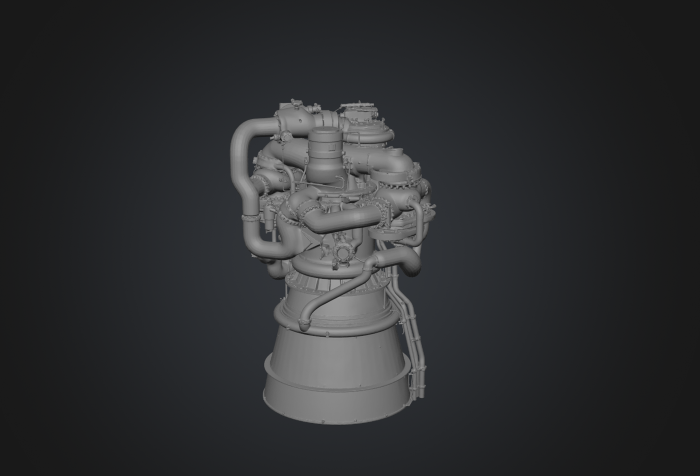
Overview:
The SDI RM 4000 is a reusable, high-performance, oxidizer-rich staged combustion cycle engineburning liquid oxygen and RP-1 kerosene designed by SDI Rocket Engines. The RM 4000 engine is designed to produce 5,100 kN of sea-level thrust at a chamber pressure of approximately 26 MPa, with a specific impulse of approximately 305 seconds at sea level and 330 seconds in vacuum.


Design:
The RM 4000 employs an oxidizer-rich staged combustion (ORSC) cycle where the entire liquid oxygen flow and a small bleed of RP-1 fuel are combusted in a single preburner to produce a hot, oxygen-rich gas that drives both the oxidizer and fuel turbopumps on a common shaft. The oxidizer rich turbine exhaust is then injected into the main combustion chamber where itserves as the oxidizer for the primary combustion process with the bulk of the RP-1 fuel. Liquid oxygen enters the engine at the low-pressure oxidizer turbopump (LPOTP) inlet at approximately 0.45 MPa. The LPOTP, an axial-flow inducer driven by a hydraulic turbine tapped from the high-pressure pump discharge, raises the LOX pressure to approximately 2.8 MPa, providing sufficient net positive suction pressure to suppress cavitation at the high-pressure oxidizer turbopump (HPOTP) inlet. The HPOTP is a single-stage centrifugal pump and raises the LOX pressure to approximately 38 MPa. From the HPOTP discharge the LOX flow splits, approximately 98% is directed to the preburner where it is combusted with a small RP-1 bleed while the remaining ~2% bypasses the preburner and is injected directly into the MCC as liquid film coolant along the chamber wall. The preburner's hot, oxygen-rich exhaust gas then passes through the single-shaft turbine, exits at approximately 28.5 MPa, and enters the MCC injector as the primary oxidizer stream. Fuel (RP-1) meanwhile enters the engine at the low-pressure fuel turbopump (LPFTP) inlet at approximately 0.35 MPa. The LPFTP raises the pressure to approximately 3.5 MPa. The high-pressure fuel turbopump (HPFTP), a single-stage centrifugal pump on the same shaft as the HPOTP, raises the RP-1 pressure to approximately 42 MPa. From the HPFTP discharge, the RP-1 flow splits three ways: approximately 3–5% is routed to the preburner as the fuel component, approximately 60–65% passes through the regenerative cooling jacket of the MCC and nozzle before entering the MCC injector as warm, partially cracked kerosene; and the remaining 30–35% enters the MCC injector directly as subcooled liquid through dedicated fuel injectors.

The RM 4000 uses a single-shaft turbopump configuration in which the high-pressure oxidizer pump, the high-pressure fuel pump, and the single-stage impulse turbine are all mounted on a common rotor supported by two angular contact ball bearings and one roller bearing. This arrangement simplifies the mechanical design, eliminates the need for inter-pump gearing or separate turbine drive shafts, and provides inherent speed synchronization between the two pumps. The High-Pressure Oxidizer Turbopump (HPOTP) is a single-stage centrifugal pump with a fully shrouded impeller machined from a single forging of Monel K-500 nickel-copper alloy (selected for its compatibility with high-pressure liquid and gaseous oxygen). The pump operates at approximately 12,800 RPM and produces a pressure rise of approximately 35.2 MPa at a flow rate of 14,700 kg/s of LOX. The volute and diffuser are cast from Inconel 718 alloy. The High-Pressure Fuel Turbopump (HPFTP) is also a single-stage centrifugal pump with a fully shrouded impeller, machined from a single forging of Ti-5Al-2.5Sn ELI (Extra Low Interstitials) Grade 6, alpha-phase titanium alloy optimized for cryogenic temperatures. The HPFTP operates at the same 12,800 RPM as the HPOTP (on a common shared shaft) and produces a pressure rise of approximately 38.5 MPa at a flow rate of 5,450 kg/s of RP-1. The higher pressure rise compared to the HPOTP compensates for the additional pressure losses in the regenerative cooling circuit that the fuel must traverse before reaching the MCC. The turbine is a two-row velocity-compounded (Curtis) impulse stage, designed to extract the required power at a low pressure ratio (1.137) and moderate rotational speed. The first-row rotor blades are investment-cast single-crystal CMSX-4 nickel superalloy with internal convection cooling passages and an external yttria-stabilized zirconia (YSZ) thermal barrier coating approximately 150 μm thick. The second-row rotor blades are uncooled IN718. The nozzle/stator vanes are also single-crystal CMSX-4. Total blade count is 89 in the first row and 107 in the second row, with a nozzle vane count of 46. The turbine tip speed is approximately 370 m/s, well within the structural capability of the single-crystal blades. The design life of the turbine section is 36,000 seconds of cumulative hot-fire time, corresponding to approximately 100 nominal mission duty cycles of 155 seconds each with margin for engine start and shutdown transients, ground testing, and acceptance test firings. The high-pressure turbopump's rolling-element bearings are the primary life-limiting components in the turbomachinery. The RM 4000 employs hybrid ceramic bearings consisting of silicon nitride (Si₃N₄) rolling elements in M50 steel races that offer significantly longer service life than all-steel bearings due to the lower density of the ceramic balls (reducing centrifugal loading), their superior surface finish (reducing wear), and their self-lubricating properties in the presence of trace LOX or kerosene films. Bearing coolant is provided by filtered, temperature-controlled RP-1 tapped from the HPFTP discharge. Interpropellant seals between the LOX-side and RP-1-side of the common shaft are critical safety components that prevent mixing of oxidizer and fuel within the turbopump cavity. The RM 4000 uses a triple-seal arrangement consisting of a primary LOX-side labyrinth seal, a helium-purged intermediate cavity, and a primary fuel-side labyrinth seal. The helium purge cavity is maintained at a slightly higher pressure than either propellant side, ensuring that any leakage is helium into the propellant streams rather than propellant into the purge cavity. Seal wear is monitored in real time by measuring helium flow rate into the purge cavity an increase above a threshold value triggers an EHM caution flag. Each propellant feed line of the engine further includes a low-pressure turbopump (boost pump) upstream of the high-pressure turbopump. These boost pumps are designed to raise the propellant inlet pressure sufficiently to prevent cavitation at the HPOTP and HPFTP inlets, even with relatively low tank pressurization levels. The Low-Pressure Oxidizer Turbopump (LPOTP) is an axial-flow inducer pump driven by a single-stage hydraulic turbine. The hydraulic turbine is powered by a tap-off of high-pressure LOX from the HPOTP discharge which is throttled through an orifice, expanded through the turbine, and recombined with the main LOX flow downstream of the inducer. The LPOTP operates at approximately 5,200 RPM and produces a pressure rise of approximately 2.35 MPa. The Low-Pressure Fuel Turbopump (LPFTP) is similarly an axial-flow inducer driven by a hydraulic turbine tapped from the HPFTP discharge. It operates at approximately 6,800 RPM and produces a pressure rise of approximately 3.15 MPa. Both low-pressure pumps use hydrostatic journal bearings lubricated by the working fluid (LOX or RP-1), eliminating rolling-element bearing wear as a life-limiting factor.

The RM 4000 preburner is a compact, cylindrical combustion chamber that operates at a pressure of 32.8 MPa and an oxidizer-to-fuel ratio of approximately 56:1 by mass. At this mixture ratio the combustion gas is overwhelmingly composed of gaseous oxygen (~94% by mass), with minor fractions of CO₂, H₂O, CO, and soot-free hydrocarbon fragments. The gas temperature of 810 K is low enough to be compatible with nickel superalloy turbine materials but high enough to deliver the required turbine work. The preburner injector uses 271 coaxial swirl injection elements arranged in a concentric ring pattern on a faceplate manufactured by laser powder bed fusion (LPBF) from Inconel 718. Each element consists of an inner fuel post that delivers a swirling annular film of RP-1 surrounded by an outer oxidizer annulus that delivers LOX. The swirl imparted to the fuel stream promotes rapid atomization and mixing. The faceplate is regeneratively cooled by a fraction of the incoming RP-1 flow that passes through internal cooling channels before being injected through the fuel posts. This cooling scheme is designed to maintain the faceplate temperature well below the oxidation threshold of IN718, even in the aggressive oxygen-rich environment. Combustion stability in the preburner is ensured by acoustic cavities (Helmholtz dampers) machined into the injector faceplate rim and by the inherent stability characteristics of the coaxial swirl injection pattern. The main combustion chamber s a regeneratively cooled, convergent-divergent thrust chamber that operates at a nominal chamber pressure of 26.2 MPa and an overall mixture ratio of 2.70:1 (O/F by mass). The combustion gas temperature at the injector end is approximately 3,680 K, and the characteristic velocity (c*) is 1,805 m/s with a c* efficiency of 99.5%. The MCC liner is fabricated from a CuCrZr alloy that offers the high thermal conductivity necessary for effective regenerative cooling at extreme heat fluxes. The liner is produced as a single-piece near-net-shape forging, after which the regenerative cooling channels are formed by ultrafast laser drilling, a process which creates hundreds of axial cooling channels approximately 1.2 mm wide and 3.5 mm deep along the inner surface of the liner. The channels are then closed out by electrodepositing a structural nickel jacket over the channel tops. The peak hot-wall heat flux occurs at the throat, where it reaches approximately 160 MW/m². RP-1 enters the cooling jacket at the nozzle end of the MCC, flows forward (counterflow to the combustion gas), and exits at the injector end at a temperature of approximately 450 K. At this temperature, the RP-1 has undergone some degree of thermal cracking, which is beneficial as the endothermic cracking reaction absorbs additional heat from the wall. A structural closeout jacket of electrodeposited nickel surrounds the CuCrZr liner, providing the mechanical strength to contain the high chamber pressure (26.0 MPa) while the liner handles the thermal load. The jacket is approximately 8 mm thick and is bonded to the liner during the electrodeposition process. The MCC chamber has a contraction ratio (chamber-to-throat area) of 3.2:1, a cylindrical section length of approximately 380 mm, and a throat diameter of 375 mm. The convergent section uses a smooth, bell-shaped contour that minimizes boundary-layer separation and combustion-gas recirculation. The main injector uses a coaxial swirl element pattern with 547 injection elements arranged in 12 concentric rings. Each element consists of an inner fuel post carrying warm RP-1 (approximately 450 K, partially cracked) and an outer annulus carrying oxidizer-rich gas from the turbine exhaust. The fuel posts impart a tangential swirl component to the RP-1, producing a hollow-cone spray that is sheared and atomized by the surrounding high-velocity oxidizer gas stream. The oxidizer gas enters the elements at approximately 250 m/s and 750 K. The injector faceplate is manufactured by LPBF additive manufacturing in Inconel 718, allowing complex internal manifolding, integrated acoustic damping cavities, and cooling passages to be produced as a single monolithic part. Combustion stability is addressed by four complementary measures: Helmholtz acoustic damper cavities integrated into the faceplate periphery, tuned to the first tangential (1T) acoustic mode of the chamber; acoustic absorber baffles (five radial blades extending approximately 40 mm into the chamber from the injector face); careful matching of injection element impedance to suppress coupling between the propellant feed system and chamber acoustic modes; and the inherent stability of the high-density, high-velocity coaxial swirl injection pattern, which provides strong viscous damping at the injector face.

The RM 4000 ignition system consists of a dual-redundant augmented spark igniter (ASI) system for both the preburner and the main combustion chamber. Each ASI contains a spark plug and independent propellant (GOX/RP-1) feed lines that create a small pilot flame prior to main propellant valve opening. The preburner is ignited first, once preburner combustion is confirmed (by chamber pressure and optical flame detectors) the main oxidizer valve is opened and the turbine then spools up, followed by main fuel valve opening and MCC ignition. The entire start sequence from ignition command to mainstage (full thrust) takes approximately 3.2 seconds. The start sequence is controlled by the engine digital controller and is fully automated, no ground-side commanding is required after the initial ignition signal. The ignition system is designed for unlimited restarts without refurbishment, enabling the multiple-burn mission profiles required for booster landing (boostback, reentry, landing burns). Each ASI spark plug is rated for 10,000 ignition cycles. The engine main oxidizer valve (MOV) is a pneumatically actuated, hydraulically damped ball valve in the main LOX feed line downstream of the HPOTP. The MOV controls engine start and shutdown and provides gross thrust modulation. Actuation time from closed to full open is approximately 350 ms. The Main Fuel Valve (MFV) is an identical ball valve in the main RP-1 feed line located downstream of the HPFTP which is sequenced with the MOV during start and shutdown. The Oxidizer Preburner Valve (OPV) is a variable-position, electromechanically actuated sleeve valve that meters LOX flow to the preburner. The OPV is the primary thrust control mechanism, by adjusting the LOX flow to the preburner the preburner gas temperature and mass flow rate can be varied, which changes the turbine power, turbopump speed, and thus the overall propellant flow rate and chamber pressure. Thrust modulation from 40% to 105% is achieved by varying the OPV position. The fuel preburner Valve (FPV) is a variable-position sleeve valve that meters RP-1 flow to the preburner. The FPV works in concert with the OPV to maintain the desired preburner mixture ratio across the throttle range. Chamber Coolant Valve (CCV): A variable-position valve that controls the fraction of RP-1 routed through the regenerative cooling circuit versus the direct-injection bypass. The CCV is adjusted as a function of thrust level to maintain appropriate cooling jacket temperatures at all operating points. All valve actuators are powered by engine-driven hydraulic and pneumatic systems, eliminating the need for vehicle-level hydraulic power during engine operation. The RM 4000 engine nozzle is a truncated ideal contour (TIC) bell nozzle with an area ratio of 25:1.The nozzle is fabricated in two sections. The upper section, from the throat to approximately 10:1 area ratio, is a regeneratively cooled extension of the MCC liner , CuCrZr alloy with laser-drilled cooling channels carrying RP-1. This region experiences the highest heat flux downstream of the throat (approximately 25 MW/m² at the throat-adjacent section). The lower section, from 10:1 to 25:1 area ratio, is a radiatively cooled structure fabricated from C-103 niobium alloy coated with a disilicide (R512E) oxidation-resistant coating. The radiatively cooled section operates at a wall equilibrium temperature of approximately 1,300–1,500 K, within the capability of coated C-103.


Control:
Each RM 4000 engine incorporates a dedicated engine digital controller (EDC), a self-contained, dual-redundant embedded computer that manages all engine functions: start and shutdown sequencing, thrust and mixture ratio control, valve positioning, ignition system firing, and interface with the engine health management system. The EDC receives high level commands from the vehicle flight computer (e.g., "throttle to 72%," "shutdown," "gimbal to +3.2° pitch") and autonomously executes the required valve, igniter, and actuator sequences. The dual redundant architecture uses two independent processor channels running identical software, with a hardware voter that selects the output of the primary channel unless it disagrees with the secondary, in which case the secondary assumes command. The EDC communicates with the vehicle flight computer via a redundant fiber optic data bus and receives power from the vehicle electrical bus. In the event of a complete loss of communication with the vehicle computer, the EDC can autonomously command a safe engine shutdown. The RRM 4000 EHM system monitors engine parameters including vibration, turbopump speed, temperatures, pressures. and flow rates throughout the engine in real time at sampling rates between 1 kHz and 50 kHz. To measure engine vibration six triaxial accelerometers are mounted on the high-pressure turbopump housing, preburner, MCC, and gimbal block. These sensors capture both broadband vibration levels and narrowband spectral signatures associated with turbopump rotordynamics, bearing defects, and combustion instability. Vibration data is processed on-board by the EDC using fast Fourier transform (FFT) algorithms, and amplitudes at critical frequencies (synchronous, sub-synchronous, and combustion acoustic modes) are compared to redline thresholds. Turbopump speeds are measured by redundant magnetic pickup sensors on both the high-pressure and low-pressure pump shafts which measure rotational speed with an accuracy of ±5 RPM. Speed excursions outside the nominal band are an early indicator of bearing degradation, seal rub, or cavitation. Temperature measurements are taken from over 40 thermocouples and resistance temperature detectors (RTDs) which monitor critical temperatures including turbine inlet, turbine discharge, preburner injector faceplate, MCC throat hot-wall (via embedded thermocouples in the CuCrZr liner), bearing coolant, and nozzle extension skin temperature. More than 25 pressure transducers monitor pressures at the pump inlets and discharges, preburner chamber, MCC chamber (redundant), nozzle base (for separation detection), and the helium interpropellant seal purge cavity. Turbine flowmeters in the main LOX and RP-1 feed lines measure propellant flow rates for mixture ratio control and performance tracking. Additionally two high-bandwidth photodiodes view the preburner combustion zone and the MCC injector face, detecting ignition confirmation and real-time combustion intensity fluctuations. A spectral emission sensor at the turbine exhaust duct monitors for the presence of metallic emission lines (iron, nickel, copper) that indicate turbine blade or bearing material erosion. The EHM system maintains a continuously updated fault model with approximately 150 monitored parameters and associated redline thresholds. After each flight, the full-rate EHM data set (approximately 120 GB per engine per flight) is downloaded from the EDC's solid-state data recorder and analyzed by ground-based machine learning algorithms that compare the engine's performance and signature data to its historical baseline and to the fleet-wide database.
Last edited by The Technocratic Syndicalists on Wed May 13, 2026 9:39 am, edited 3 times in total.
SDI AG
Arcaenian Military Factbook
Task Force Atlas
International Freedom Coalition


OOC: Call me Techno for Short
IC: The Kingdom of Arcaenia

User avatar
The Technocratic Syndicalists
Minister
 
Posts: 2349
Founded: May 27, 2015
Inoffensive Centrist Democracy

Postby The Technocratic Syndicalists » Tue May 12, 2026 4:23 pm

Image


RM 2100

  • Type:
    Liquid-fuel engine
  • Propellant:
    LOX/LH-2
  • Mixture Ratio:
    6.0:1
  • Cycle:
    Full-flow staged combustion
  • Length:
    4,500 mm
  • Diameter:
    2,500 mm
  • Dry Weight:
    3,100 kg
  • Nozzle Ratio:
    60:1
  • Thrust (sl):
    3,050 kN
  • Thrust (vac):
    3,300 kN
  • Throttle Range:
    100% to 65%
  • Thrust-to-weight ratio:
    100:1
  • Chamber Pressure:
    30 MPa
  • Isp (sl):
    394 seconds
  • Isp (vac):
    467 seconds


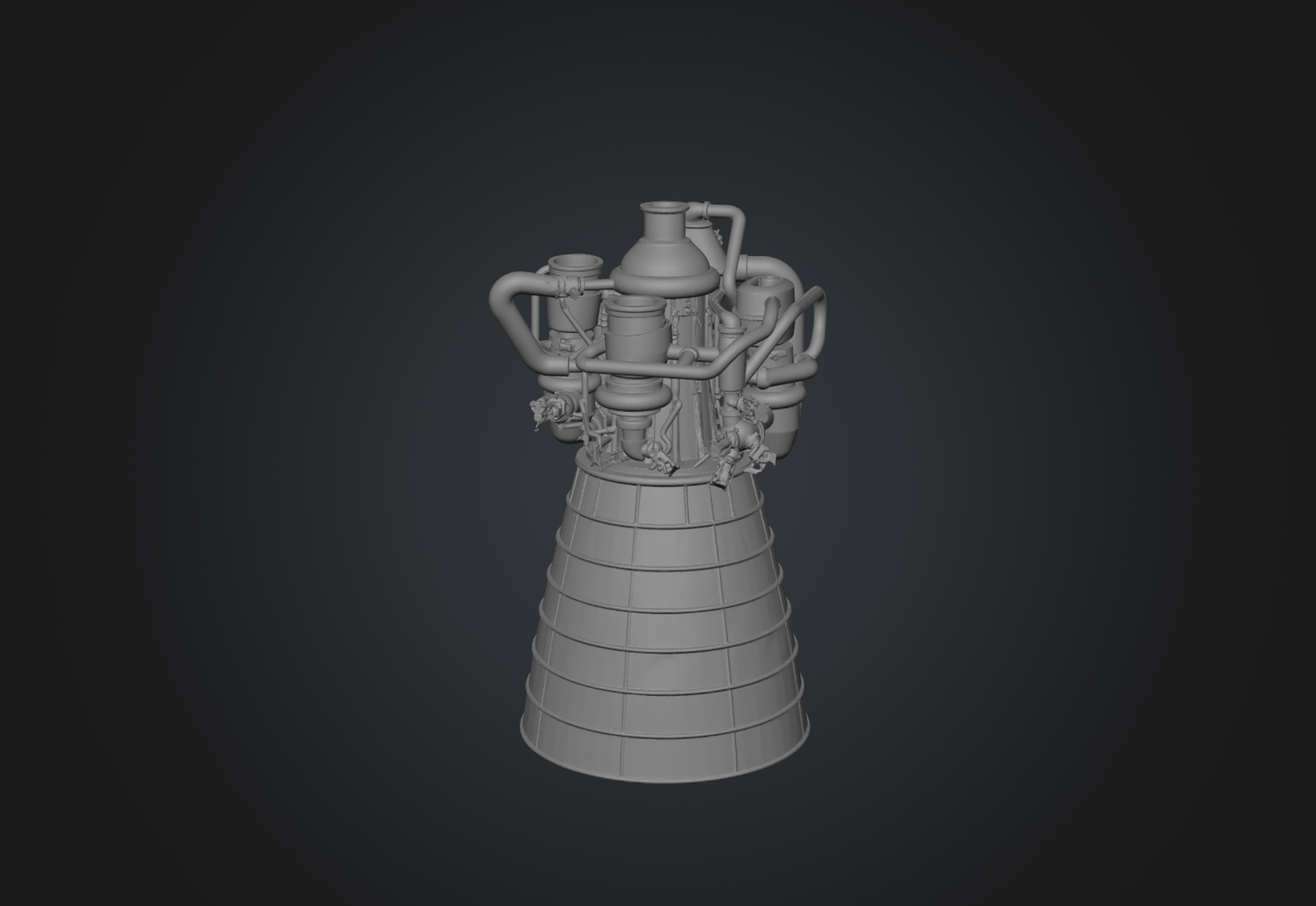
Overview:
The SDI RM 2100 is a reusable, high-performance, full-flow staged combustion cycle engine burning liquid oxygen and liquid hydrogen designed by SDI Rocket Engines.


Design:
The RM 2100 engine is an advanced full-flow staged combustion cycle engine burning liquid oxygen and liquid hydrogen. The RM 2100 employs a full-flow staged combustion cycle in which both propellants are fully gasified before entering the main combustion chamber. In the Oxidizer-rich preburner (OPB) all of the LOX and a small fraction (~8% by mass) of the LH₂ are combusted, producing a hot, steam-rich, oxygen-dominated gas at approximately 850 K and 36.5 MPa. This gas drives the oxidizer turbopump turbine. In the separate fuel-rich preburner (FPB) all of the LH₂ and a small fraction (~3% by mass) of the LOX are combusted, producing a hot, hydrogen-rich gas at approximately 950 K and 37.2 MPa. This gas drives the fuel turbopump turbine. The oxidizer turbine exhaust (hot GOX-rich gas) and the fuel turbine exhaust (hot GH₂-rich gas) are then injected into the main combustion chamber, where they mix and combust at the full design mixture ratio of 6.0:1 (O/F). As both propellants enter the MCC as hot gases, combustion is extremely rapid, uniform, and thermodynamically efficient with no liquid atomization or vaporization delay, and the injector-to-throat distance can be shorter than in engines with liquid injection. The RM 2100 manages the power balance of both preburner-turbopump loops through a model-predictive control (MPC) algorithm running on the engine digital controller. The MPC uses a real-time simplified thermodynamic model of the engine to predict the effect of valve position changes on both loops simultaneously, and computes optimal valve trajectories to reach the commanded thrust and mixture ratio setpoint with minimal transient overshoot. This approach replaces the single-input/single-output PID control loops used in simpler engine cycles and is required for stable operation during throttle transients, particularly the deep throttle maneuvers required for landing.

The RM 2100 High-Pressure Oxidizer Turbopump (HPOTP) is a single-stage centrifugal pump driven by a two-stage axial reaction turbine on a dedicated shaft. The pump impeller is machined from a single forging of Monel K-500 for LOX compatibility and operates at approximately 18,500 RPM, producing a pressure rise of approximately 39.8 MPa at a LOX flow rate of 6,600 kg/s. The turbine is driven by the oxidizer-rich preburner exhaust gas (850 K, predominantly GOX). The two-stage axial turbine uses IN718 blades with no active cooling. The turbine extracts 38 MW at a pressure ratio of 1.175. The HPOTP employs hydrostatic journal bearings, fluid film bearings in which a thin layer of high-pressure LOX is maintained between the bearing surfaces by an external pressurization source (tapped from the pump discharge). The hydrostatic bearings eliminate metal-to-metal contact, producing essentially zero wear and conferring a service life limited only by fatigue of the rotating components (shaft, impeller, turbine disks), which is designed for a 100 mission service life. The High-Pressure Fuel Turbopump (HPFTP) is a three-stage centrifugal pump driven by a two-stage axial reaction turbine on its own dedicated shaft. Three pump stages are required because liquid hydrogen's very low density necessitates enormous head rise per unit mass flow to achieve the required discharge pressure. The pump operates at approximately 36,000 RPM and produces a total pressure rise of approximately 42.5 MPa at an LH₂ flow rate of approximately 1,100 kg/s. The three pump stages are arranged in series on a common shaft, with inter-stage diffuser passages. Each stage uses a shrouded centrifugal impeller machined from Ti-5Al-2.5Sn ELI titanium alloy. Impeller blanks are produced by hot isostatic pressing (HIP) followed by finish machining to achieve the required dimensional tolerances and surface finish. The fuel turbine is driven by the fuel-rich preburner exhaust gas (950 K, predominantly GH₂). The two-stage axial turbine uses single-crystal CMSX-4 blades. The turbine extracts 86 MW at a pressure ratio of 1.205. Like the HPOTP, the HPFTP uses hydrostatic journal bearings, in this case pressurized by high-pressure GH₂ tapped from the pump discharge. The use of gaseous hydrogen as the bearing fluid requires careful attention to seal design to prevent hydrogen leakage into the turbine cavity, where it could contact hot turbine structures and auto-ignite. The RM 2100 uses a labyrinth-purge-labyrinth seal arrangement similar in concept to the interpropellant seals on the RM 4000 but adapted for the hydrogen environment. Both the LOX and LH₂ feed paths include low-pressure boost pumps upstream of the high-pressure turbopumps, serving as cavitation-suppression systems. The LPOTP is an axial-flow inducer driven by a small hydraulic turbine powered by high-pressure LOX from the HPOTP discharge and has an operating speed approximately 6,500 RPM and produces a pressure rise of approximately 1.8 MPa. The LPFTP is an axial-flow inducer driven by a hydrogen-gas turbine powered by a tap of warm GH₂ from the fuel-rich preburner exhaust with an operating speed approximately 15,000 RPM and produces a pressure rise approximately 1.2 MPa. The LPFTP's high operating speed reflects the very large volumetric flow rate of low-density liquid hydrogen.

The RM 2100 Oxidizer-Rich Preburner (OPB) operates at 36.5 MPa and an O/F ratio of 12.5:1 by mass, producing a hot gas at approximately 850 K that is predominantly gaseous oxygen with some steam (H₂O). The OPB injector uses 198 coaxial shear elements that inject LOX as a swirled liquid annulus with a central gaseous hydrogen jet. The injector faceplate is LPBF-manufactured IN718 with integrated regenerative cooling channels fed by a small fraction of the incoming LH₂ flow. The Fuel-Rich Preburner (FPB) operates at 37.2 MPa and an O/F ratio of 0.80:1 by mass, producing a hydrogen-rich gas at approximately 950 K. The FPB injector uses 162 coaxial elements that inject LH₂ as a swirled annulus with a central LOX jet. The hydrogen-rich gas is clean and non-coking, and the FPB environment is entirely compatible with nickel superalloy hardware. The FPB operates at a slightly higher pressure than the OPB (37.2 vs. 36.5 MPa) asthe fuel turbine requires a higher pressure ratio (1.205 vs. 1.175) to extract the greater power needed by the HPFTP. This pressure difference is established by the relative sizing of the preburner throat areas and the main injector backpressure characteristics. The Main Combustion Chamber operates at 30.0 MPa and an overall mixture ratio of 6.0:1, producing a combustion temperature of approximately 3,530 K and a characteristic velocity of 2,386 m/s. The MCC liner is fabricated from a GRCop-42 copper alloy (Cu-4Cr-2Nb), a dispersion-strengthened copper alloy that retains high thermal conductivity (approximately 300 W/m·K at operating temperature) and high strength at elevated temperatures. The liner is produced using laser powder bed fusion additive manufacturing, which allows the regenerative cooling channels to be integrated directly into the wall during the build process, no post-machining of channels or separate closeout step is required. The cooling circuit uses supercritical hydrogen (approximately 50–80 K at inlet, 250–400 K at outlet) as the regenerative coolant, exploiting hydrogen's extraordinary heat capacity and thermal conductivity. Peak hot-wall heat flux at the throat is approximately 130 MW/m², the heat flux and the cooling properties of hydrogen resulting in comfortable thermal margins for the GRCop-42 liner. The RM 2100 main injector receives two gas streams, the oxidizer-rich gas from the OPB turbine exhaust and fuel-rich gas from the FPB turbine exhaust. The injector employs 421 coaxial gas-gas elements arranged in 10 concentric rings with each element consisting of an outer annulus carrying oxidizer-rich gas (at approximately 700 K and 150 m/s) and an inner post carrying fuel-rich gas (at approximately 800 K and 280 m/s). The velocity differential between the two streams provides the shear mixing necessary for rapid and complete combustion. Gas-gas injection provides inherent combustion stability advantages over gas-liquid or liquid-liquid injection, the absence of droplet vaporization eliminating the time-delay coupling mechanism that drives most forms of high-frequency combustion instability. The injector faceplate is a single LPBF-manufactured part in Inconel 718, integrating all 421 elements, internal manifolding for both gas streams, and peripheral acoustic damping cavities. The RM 2100 uses a spark-torch ignition system for both preburners and the MCC. Each igniter is a small GH₂/GOX torch igniter that creates a pilot flame using spark-initiated combustion of gaseous hydrogen and oxygen stored in small high-pressure bottles. The ignition sequence starts with the FPB torch igniter firing first, establishing a fuel-rich pilot flame. The FPB main propellant valves then open and the fuel-side turbopump begins to spool. As the fuel turbine reaches approximately 15% design speed, the OPB torch igniter fires and the OPB propellant valves open, the oxidizer turbopump spools up,and finally the MCC torch igniters fire and the main injection of both gas streams begins. Total start sequence duration is approximately 4.8 second. The ignition system is rated for unlimited restarts. The ship requires at minimum three engine starts per mission: initial orbital insertion burn, deorbit burn, and landing burn. Additional restarts may be required for orbit-raising maneuvers, rendezvous phasing burns, or abort scenarios.

The RM 2100 nozzle is divided into three sections: Throat and upper section (to ~10:1 area ratio) are constructed from regeneratively cooled GRCop-42, integral with the MCC liner. Cooling channels carry supercritical hydrogen in a counterflow arrangement. The nozzle mid-section (10:1 to 40:1) is employs regeneratively cooled tubular construction using Inconel 625 tubes brazed into a structural shell. The tubular construction is designed to be more cost-effective than machined-channel liners at these larger diameters and lower heat fluxes. Coolant is hydrogen tapped from the regenerative circuit. The nozzle lower extension (40:1 to 90:1) is constructed from radiatively cooled niobium alloy C-103 with R512E disilicide coating. This section operates at a wall equilibrium temperature of approximately 1,100 ro 1,350 K and is attached to the mid-section by a bolted flange with a metallic C-seal, allowing field removal for inspection or replacement. Flexible propellant ducts at the engine inlet use multi-ply Inconel 625 bellows with internal flow liners to prevent bellows fatigue from high-velocity cryogenic fluid flow. The bellows assemblies are designed for 50,000 full-amplitude gimbal cycles, far exceeding the cumulative requirement for 100 missions.


Control:
The RM 2100 EHM system monitors approximately 180 parameters, including vibration, speeds, temperatures, pressures, and flow rates with additional sensors specific to the dual-preburner architecture interpropellant seal monitoring. Mass spectrometer sensors at each seal purge cavity continuously analyze the purge gas composition for traces of cross-contamination. Detection of hydrogen in an oxygen-side cavity, or vice versa, triggers an immediate caution or warning flag depending on concentration levels. Preburner cross-talk monitoring consists of dynamic pressure transducers in both preburners which monitor for acoustic coupling between the two preburner volumes, which could indicate a resonance condition that might destabilize one or both preburners. Hydrogen embrittlement monitoring consists of strain gauges on the HPFTP housing and the fuel-side turbine disk rim monitor for anomalous strain accumulation that could indicate hydrogen-assisted fatigue cracking. These sensors feed a fracture-mechanics model running on the ground-based post-flight analysis system that tracks remaining fatigue life of safety-critical rotating components. The RM 2100 EHM uses a three-tier redline system (caution, warning, critical) with the addition of a "preemptive shutdown" mode specific to the dual-preburner architecture. If the MPC algorithm detects that the engine's thermodynamic state is diverging from the predicted trajectory (indicating a possible loss of power balance control), it can command a controlled shutdown (orderly valve closure over approximately 1.5 seconds) before any individual parameter reaches a redline threshold.
Last edited by The Technocratic Syndicalists on Thu May 14, 2026 8:34 pm, edited 4 times in total.
SDI AG
Arcaenian Military Factbook
Task Force Atlas
International Freedom Coalition


OOC: Call me Techno for Short
IC: The Kingdom of Arcaenia

User avatar
The Technocratic Syndicalists
Minister
 
Posts: 2349
Founded: May 27, 2015
Inoffensive Centrist Democracy

Postby The Technocratic Syndicalists » Wed May 13, 2026 10:02 am

Image

RM 3300

  • Type:
    Liquid-fuel engine
  • Propellant:
    LOX/LH-2
  • Mixture Ratio:
    6:1
  • Cycle:
    Full flow staged combustion
  • Length:
    5,600 mm
  • Width:
    4,500 mm
  • Dry Weight:
    2,075 kg
  • Nozzle Ratio:
    170:1
  • Thrust (vac):
    2,900 kN
  • Thrust (sl):
    2,500 kN
  • Throttle Range:
    100% to 50%
  • Thrust-to-weight ratio:
    130:1
  • Chamber Pressure:
    30.5 MPa
  • Isp (vac):
    485 seconds
  • Isp (sl):
    410 seconds


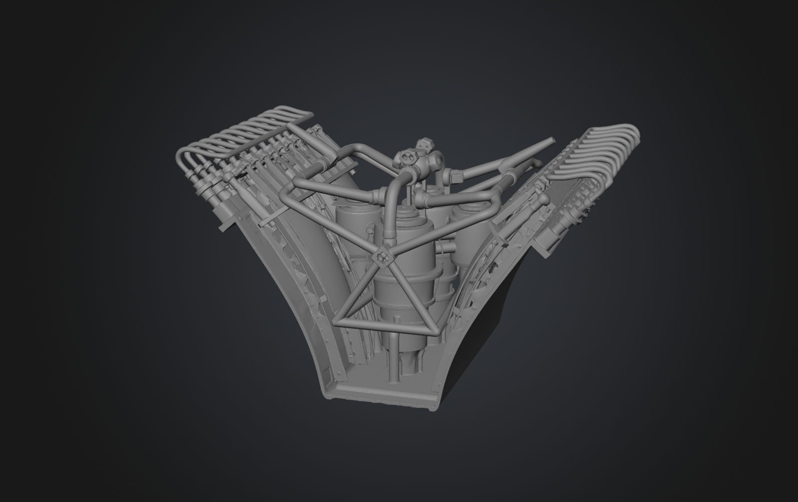
Overview:
The SDI RM 3300 is an advanced altitude-compensating linear aerospike rocket engine designed by SDI Rocket Engines. The RM 3300 employs a full-flow staged combustion (FFSC) thermodynamic cycle burning slush hydrogen (SLH2) fuel and subcooled liquid oxygen (scLOX) oxidizer. The RM 3300 is designed as a symmetric, modular assembly of two identical half-modules each constituting a fully self-contained propulsion unit consisting of its own complete FFSC turbomachinery set (one oxidizer-rich preburner with LOX turbopump, one fuel-rich preburner with LH2 turbopump), a row of twenty individual thrust cell combustion chambers, and one expansion ramp surface forming one half of the truncated two-dimensional aerospike nozzle. The two half-modules are mated back-to-back along the central nozzle plane, with their respective expansion ramps forming the complete truncated spike. This modular architecture enables independent manufacturing, testing, and qualification of each half-module, reduces the risk of total engine loss from a single-point turbomachinery failure, and provides inherent engine-out-within-an-engine redundancy. The engine operates at a main combustion chamber pressure exceeding 30 MPa, enabled by the thermodynamic efficiency of the full-flow staged combustion cycle in which both propellants are fully gasified before entering the main combustion chambers. This high chamber pressure, combined with the altitude-compensating aerospike nozzle, delivers a specific impulse of 400 seconds at sea level and 480 seconds in vacuum, with an engine thrust-to-weight ratio exceeding 100.


Design:
The RM 3300 engine is designed as two identical, mirror-symmetric half-modules. Each half-module is a fully functional propulsion unit that can be independently manufactured, assembled, acceptance-tested, and installed into the vehicle. The complete RM 3300 engine is formed by mating two half-modules along the central plane of the aerospike nozzle, with their respective expansion ramps facing each other to form the truncated two-dimensional spike. Each half-module contains a full-flow staged combustion turbomachinery set with one oxidizer-rich preburner (OPB) driving one LOX turbopump assembly and one fuel-rich preburner (FPB) driving one LH2 turbopump assembly, a combustion chamber row of twenty individual thrust cells arranged in a linear array along the upper edge of the expansion ram, one half of the truncated two-dimensional aerospike nozzle, high-pressure oxidizer and fuel manifolds distributing propellant from the turbopump discharges to the thrust cell injectors, and low-pressure inlet manifolds receiving propellant from the vehicle feed system, and an engine controller unit (ECU) consisting of a dedicated half-module engine controller managing the FFSC cycle start, steady-state operation, throttling, and shutdown for that half-module. The two half-module ECUs communicate over a redundant data bus to coordinate engine-level functions such as synchronous throttling and health management. The two half-modules are joined at the central nozzle plane by a structural backbone beam that runs the full width of the engine (4.5 m). The backbone provides the structural reference for alignment of the two ramp surfaces, carries the combined thrust load into the vehicle thrust structure, and provides mounting for the base closeout assembly. The half-module-to-backbone interface uses precision machined titanium-aluminide tongue-and-groove joints with preloaded high-strength bolting, allowing field separation and replacement of individual half-modules without disturbing the mating half-module or the vehicle thrust structure. Propellant feed interfaces between the vehicle tankage and each half-module are independent, with each half-module receiving propellant through its own set of prevalves and flex joints. This independence means that a complete half-module failure, including turbomachinery seizure, preburner failure, or propellant manifold leak, can be isolated by closing the prevalves to that half-module while the opposite half-module continues to operate at full power. The engine therefore provides inherent 50%-thrust engine-out capability at the individual engine level, before considering the vehicle-level engine-out capability provided by the seven-engine cluster.

Each RM 3300 half-module contains two independent turbopump assemblies: the oxidizer turbopump assembly (OTPA) and the fuel turbopump assembly (FTPA). Each assembly integrates a preburner, a turbine driven by that preburner’s hot gas, and a propellant pump on a common shaft. The four turbopump assemblies in a complete RM 3300 engine represent the highest power density rotating machinery in the system, collectively producing approximately 105 MW of shaft power at full thrust. The LOX pump is a two-stage centrifugal design with a diffusing volute collector at each stage exit. The impellers are open-faced, integrally bladed disk (blisk) forgings machined from Monel K-500. The pump inlet operates at the vehicle-supplied LOX inlet pressure of approximately 0.6 MPa with a net positive suction head (NPSH) requirement of 25 m. The pump discharge pressure is 36.2 MPa, providing the pressure rise necessary to feed the OPB at 34.2 MPa with margin for line losses and injector pressure drop. The LOX pump flow rate at full thrust is 183 kg/s per half-module. A LOX boost pump, an inducer-type axial impeller on the main pump shaft, is located at the pump inlet to raise the inlet pressure and suppress cavitation at the main impeller eye. The boost inducer is a four-bladed helical design in Monel K-500 with a tip speed of 145 m/s and a suction specific speed (Nss) of 12,200, providing a cavitation-free operating range across the full throttle band. The oxidizer-rich preburner combusts the full LOX flow (183 kg/s) with a small bleed of hydrogen fuel (approximately 4.2 kg/s, representing 13.6% of the total half-module fuel flow) at a preburner mixture ratio of approximately 43.6:1 (highly oxidizer-rich). This produces an oxidizer-rich hot gas at approximately 750 Kand 34.2 MPa. The OPB mixture ratio is chosen to maintain the turbine inlet temperature below the oxidation resistance limit of the titanium-aluminide turbine blades while providing sufficient energy to drive the LOX turbine at full power. The OPB injector uses a platelet-stack design with 180 individual injection elements, fabricated by diffusion bonding of chemically etched Monel K-500 platelets. This construction provides extremely uniform mixture ratio distribution across the injector face, preventing local stoichiometric hot spots that could damage the turbine. The LOX turbine is a two-stage axial-flow reaction turbine operating on the oxidizer-rich hot gas from the OPB. The turbine inlet conditions are 750 K and 34.2 MPa; the turbine exit conditions are approximately 670 K and 30.8 MPa, giving a pressure ratio of 1.11 per stage (1.23 overall) and a total turbine power of 23.8 MW per half-module. The turbine rotor blades are single-crystal castings of Ti-48Al-2Cr-2Nb gamma titanium-aluminide (γ-TiAl) intermetallic alloy. This alloy offers a density of only 3.9 g/cm³ (approximately half the density of nickel superalloys), a tensile strength of 450 MPa at 750 K, and excellent oxidation resistance in the mildly oxidizing OPB exhaust environment up to 800 K. The low density of γ-TiAl dramatically reduces the centrifugal blade pull load at the operating speed of 18,200 rpm, enabling a lighter disk and shaft design. The turbine nozzle guide vanes are fabricated from the same γ-TiAl alloy. The turbine disk is a dual-alloy construction with a a forged Ti-6Al-4V hub and bore region (for high fracture toughness at the bore stress concentration) and a γ-TiAl bladed rim region joined by inertia friction welding.

The hydrogen pump is a three-stage centrifugal design, reflecting the very large pressure rise required for the low-density hydrogen propellant. The impellers are closed-face titanium alloy (Ti-5Al-2.5Sn ELI, selected for hydrogen compatibility and cryogenic toughness) blisk forgings with splitter vanes at each stage to improve diffusion efficiency. The pump inlet operates at the vehicle-supplied SLH2 inlet pressure of approximately 0.35 MPa (51 psia) with an NPSH requirement of 65 m (reflecting the higher inducer tip speed needed for the low-density fluid). The pump discharge pressure is 37.5 MPa (5,439 psia). The LH2 pump flow rate at full thrust is 30.8 kg/s per half-module.A hydrogen boost inducer, a three-bladed swept-helical axial impeller on the main pump shaft, raises the inlet pressure to suppress cavitation. The inducer is fabricated from Ti-5Al-2.5Sn ELI with a tip speed of 190 m/s. The inducer blades incorporate backward-swept leading edges to minimize incidence-angle sensitivity across the throttle range, providing cavitation-free operation from 50% to 109% thrust. The fuel-rich preburner combusts the full hydrogen flow (30.8 kg/s) with a small bleed of LOX (approximately 6.8 kg/s, representing 3.7% of the total half-module LOX flow) at a preburner mixture ratio of approximately 0.22:1 which produces a fuel-rich hot gas at approximately 900 K and 35.8 MPa. The FPB injector is a coaxial swirl design with 120 injection elements, fabricated from Inconel 718 by selective laser melting (SLM) additive manufacturing with integral acoustic damping cavities to suppress combustion instability. The hydrogen turbine is a two-stage axial-flow impulse turbine operating on the fuel-rich hot gas from the FPB. The turbine inlet conditions are 900 K and 35.8 MPa while the exit conditions are approximately 780 K and 31.2 MPa, giving an overall pressure ratio of 1.15 and a total turbine power of 28.5 MW per half-module. The turbine rotor blades are directionally solidified (DS) castings of MAR-M-246, a nickel-base superalloy with excellent high-temperature strength and hydrogen compatibility. The turbine operates at a shaft speed of 72,500 rpm. The turbine disk is a forged Waspaloy monoblock design with integral fir-tree blade root slots. The turbine nozzle guide vanes are precision-cast γ-TiAl (48-2-2), leveraging the alloy’s low density to minimize the cantilevered vane mass and the aerodynamic excitation loads on the downstream rotor blades. Because the OTPA and FTPA are on separate shafts with no mechanical coupling, there is no interpropellant shaft seal. Instead, an interpropellant boundary exists at the main injector of each thrust cell, where oxidizer-rich hot gas from the OPB manifold and fuel-rich hot gas from the FPB manifold meet. This boundary is managed by the interpropellant plate (IPP), a structural barrier within each thrust cell injector assembly that separates the two hot-gas streams until they enter the combustion zone. The IPP is fabricated from a continuous-fiber silicon carbide reinforced titanium metal matrix composite (SiCf/Ti-6Al-4V MMC), which provides the high-temperature strength, stiffness, and thermal conductivity required to maintain structural integrity at the 30.5 MPa chamber pressure with the oxidizer-rich gas on one side and fuel-rich gas on the other. The IPP is actively cooled by a film of hydrogen bled from the fuel manifold, maintaining the plate temperature below 650 K under all operating conditions. Any through-crack in the IPP would result in localized combustion at the crack site, producing a detectable temperature rise on embedded thermocouples and triggering an autonomous health management response (thrust cell isolation or engine shutdown) before the damage can propagate.

Each RM 3300 half-module contains twenty individual thrust cells arranged in a linear row along the upper edge of the expansion ramp. Each thrust cell is a self-contained combustion unit consisting of an injector assembly, a combustion chamber, and a convergent throat section that transitions into the expansion ramp. The thrust cells are the primary thrust-producing elements of the engine; the aerospike ramp serves as the divergent nozzle section for all forty cells simultaneously. Each thrust cell has a roughly rectangular cross-section of 210 mm width by 180 mm depth. The cell length from injector face to throat plane is 320 mm, which is substantially shorter than a conventional bell-nozzle combustion chamber of equivalent thrust. This compact length is enabled by the fully gaseous propellant injection inherent in the FFSC cycle, because both the oxidizer-rich and fuel-rich streams enter the combustion chamber as hot gases, there is no atomization or vaporization delay, and mixing and combustion are completed within approximately 200 mm of the injector face. The thrust cell injector assembly receives oxidizer-rich hot gas at approximately 750 K and 31.5 MPa from the OPB manifold on one side of the interpropellant plate and fuel-rich hot gas at approximately 900 K and 31.8 MPa from the FPB manifold on the other side. The injector uses a tri-element coaxial pattern with 36 injection elements per cell with each element consisting of a central oxidizer-rich gas post surrounded by an annular fuel-rich gas sleeve, with a recessed cup at the element exit to promote recirculation and flame holding. The injector faceplate is fabricated from GRCop-42 (Cu-4Cr-2Nb) copper alloy by laser powder bed fusion (L-PBF) additive manufacturing with integral regenerative cooling channels in the faceplate. The GRCop-42 alloy provides a thermal conductivity of 285 W/m·K at 500 K (approximately 70% of pure copper) with a yield strength of 340 MPa at 500 K, enabling the faceplate to survive the intense radiative and convective heat flux from the combustion zone (estimated at 45 MW/m² peak) with coolant-side wall temperatures below 600 K.

The combustion chamber hot-wall liner is a GRCop-42 copper alloy structure fabricated by L-PBF additive manufacturing with integral regenerative cooling channels. The cooling channels are rectangular, 1.8 mm wide by 2.5 mm deep, spaced at 2.6 mm pitch on all four walls of the chamber and convergent section. Hydrogen coolant enters the cooling circuit at the throat (where heat flux is maximum, approximately 160 MW/m²) and flows forward toward the injector face in a counterflow arrangement, absorbing approximately 12 MW of thermal power per thrust cell. The liner wall thickness on the hot-gas side between the combustion gas and the cooling channels is 0.8 mm, optimized by conjugate heat transfer analysis to minimize the thermal stress in the copper wall while maintaining structural integrity at the 30.5 MPa internal pressure. The hot-gas-side wall temperature is maintained below 600 K at all operating conditions, within the creep and fatigue life capability of GRCop-42 at the target 500 mission engine service life. The structural jacket surrounding the GRCop-42 liner is a filament-wound continuous silicon carbide fiber reinforced titanium metal matrix composite (SiCf/Ti-6Al-4V MMC) shell which carries the hoop stress from the 30.5 MPa chamber pressure. The MMC jacket is fabricated by the foil-fiber-foil (FFF) method, in which alternating layers of Ti-6Al-4V foil and SiC fiber (SCS-6, 140 μm diameter) mats are stacked and consolidated by hot isostatic pressing (HIP) at approximately 925°C and 100 MPa. The resulting composite has a fiber volume fraction of 35%, a longitudinal tensile strength of 1,700 MPa, and a density of 3.86 g/cm³. The jacket is bonded to the GRCop-42 liner by a thin braze layer of gold-nickel alloy applied during the HIP consolidation cycle, creating a metallurgical bond that transmits pressure loads and thermal stresses between the liner and jacket. The RM 3300 thrust cell design incorporates multiple stability features. The relatively small individual cell volume raises the natural acoustic frequencies of the chamber well above the range typically susceptible to coupling with combustion dynamics. The first tangential (1T) acoustic mode of each cell is approximately 14,800 Hz, and the design provides a stability margin exceeding 20 dB on this mode. Additionally, acoustic damping is provided by an array of quarter-wave absorber cavities machined into the GRCop-42 injector faceplate around the periphery of each thrust cell. These cavities are tuned to the 1T, 2T, and 1L acoustic modes, providing broadband damping across the frequency range from 5,000 to 25,000 Hz. Bomb test (pulse gun) stability demonstrations are a required element of the engine qualification program, demonstrating recovery from a defined perturbation within 15 milliseconds.

The RM 3300 employs a truncated two-dimensional linear aerospike nozzle. In this configuration, the exhaust from the thrust cells is directed inward and downward along the contoured ramp surface, expanding against the ramp on one side and against the ambient atmosphere on the other. As the vehicle ascends and ambient pressure decreases, the free boundary of the exhaust plume expands outward, effectively increasing the nozzle expansion ratio continuously with altitude. This altitude compensation eliminates the overexpansion losses at sea level and the underexpansion losses at high altitude that penalize fixed-geometry bell nozzles, delivering near-ideal expansion at every point in the trajectory. The nozzle is composed of two ramp surfaces, one from each half-module, facing each other across the central engine plane. The exhaust from the port half-module’s twenty thrust cells flows along the port ramp, and the exhaust from the starboard half-module’s twenty cells flows along the starboard ramp. The two exhaust streams merge at the base of the truncated spike, where a base bleed flow of warm turbine exhaust gas pressurizes the recirculation region, recovering approximately 96% of the ideal full-length spike performance. Each expansion ramp is a contoured surface approximately 2.8 m long from the thrust cell throat plane to the ramp trailing edge and 4.5 m wide, spanning the full twenty-cell row. The ramp contour is defined by an isentropic method-of-characteristics (MOC) analysis, optimized for maximum time-averaged thrust coefficient over a representative ascent trajectory from sea level to vacuum. The ramp is truncated at approximately 40% of the ideal spike length, balancing the mass and structural penalty of a longer ramp against the performance recovery provided by base bleed pressurization. The ramp surface has a compound curvature, concave near the throat region (turning the exhaust flow from the thrust cell exit direction onto the ramp surface) and transitioning to a nearly flat surface near the trailing edge. The initial turning angle at the throat is approximately 28° relative to the engine centerline, decreasing to approximately 4° at the trailing edge. The ramp trailing-edge lip is radiused to prevent flow separation at the base under high-altitude, low-backpressure conditions.

The expansion ramp operates in an extreme thermal environment, with exhaust gas temperatures exceeding 3,200 K at the throat region and gas pressures of 30.5 MPa at the throat decreasing to approximately 0.1 MPa at the ramp trailing edge. The ramp is designed as a hot structure: a load-bearing thermal protection surface that directly withstands the exhaust gas environment without a separate TPS overlay. The ramp
throat region (0–0.5 m from throat) is constructed from GRCop-42 copper alloy construction with integral regenerative cooling channels, identical in concept to the thrust cell liner. Hydrogen coolant from the thrust cell cooling circuit continues through the throat region cooling channels before entering the fuel manifold. This region experiences the highest heat flux (80–160 MW/m²) and requires active regenerative cooling to maintain wall temperatures below 700 K. The mid-ramp region (0.5–1.8 m) is constructed from Gamma titanium-aluminide (γ-TiAl) alloy structural panels with film cooling. The mid-ramp panels are investment-cast Ti-48Al-2Cr-2Nb with a wall thickness of 6 mm and integral stiffening ribs on the backside. Film cooling is provided by rows of discrete laser-drilled cooling holes 0.5 mm in diameter, fed by hydrogen from the thrust cell coolant exit. The γ-TiAl alloy operates at surface temperatures up to 1,050 K in this region, well within its oxidation and creep capability. The trailing ramp region (1.8–2.8 m) is constructed from silicon carbide / silicon carbide ceramic matrix composite (SiC/SiC CMC) panels. In this region, the gas pressure is low (< 2 MPa) but the gas temperature remains high (~2,400 K), and the reduced heat flux (~5–15 MW/m²) allows radiation cooling without active film cooling. The SiC/SiC CMC panels operate at surface temperatures up to 1,500 K, using their inherent thermal radiation to reject heat. Each CMC panel is approximately 450 mm × 450 mm and is mechanically attached to a γ-TiAl subframe by floating pin joints that accommodate differential thermal expansion. The truncated ramp is closed at its trailing edge by a base closure assembly that forms a cavity between the two ramp trailing edges. Warm turbine exhaust gas, a mixture of fuel-rich and oxidizer-rich gas at approximately 700–800 K, is injected into this base cavity through a row of discrete injection ports in the base closure wall. This base bleed flow pressurizes the recirculation zone behind the truncated spike, preventing the formation of a low-pressure wake that would reduce the effective nozzle thrust. The base closure assembly is a SiC/SiC CMC shell construction, radiation-cooled to approximately 1,100 K. The base bleed mass flow rate is approximately 2.1% of the total engine propellant flow, and the base pressure achieved is approximately 35% of the ambient pressure, yielding a base thrust contribution of approximately 1.8% of total engine thrust at sea level and 4.2% in vacuum. The combined ramp and base bleed performance recovers approximately 96.3% of the ideal full-length spike thrust coefficient.


Control:
Each RM 3300 half-module is instrumented with over 340 sensors providing continuous monitoring of engine health across all operating conditions. The IEHM system performs real-time anomaly detection, predictive remaining-life estimation, and autonomous safing response concurrently. The IEHM algorithms implement model-based anomaly detection using a real-time digital twin of the FFSC cycle. The digital twin ingests all sensor data and compares measured values against predicted values based on the commanded operating point.[/list]
Last edited by The Technocratic Syndicalists on Thu Aug 27, 2026 11:28 am, edited 6 times in total.
SDI AG
Arcaenian Military Factbook
Task Force Atlas
International Freedom Coalition


OOC: Call me Techno for Short
IC: The Kingdom of Arcaenia

User avatar
The Technocratic Syndicalists
Minister
 
Posts: 2349
Founded: May 27, 2015
Inoffensive Centrist Democracy

Postby The Technocratic Syndicalists » Thu Aug 27, 2026 12:49 pm


ARM 7500

  • Type:
    Liquid-fuel engine
  • Propellant:
    LH2 (NTR mode), LOX/LH2 (LOX Augmented NTR Mode)
  • Mixture Ratio:
    3:1 (LOX Augmented NTR Mode)
  • Cycle:
    Recuperated topping expander
  • Length:
    3,800 mm
  • Width:
    3,750 mm
  • Dry Weight:
    4,500 kg
  • Nozzle Ratio:
    100:1
  • Thrust (vac):
    1,500 kN (NTR mode), 3,750 kn (LOX Augmented NTR Mode)
  • Throttle Range:
    100% to 20%
  • Thrust-to-weight ratio:
    35:1
  • Chamber Pressure:
    7.0 MPa
  • Isp (vac):
    1,000 seconds (NTR mode), 650 seconds (LOX Augmented NTR Mode)[


Overview:
The SDI ARM 7500 is pebble bed nuclear thermal rocket engine designed by SDI Rocket Engines that can operate as both a conventional nuclear-thermal rocket and in a LOX augmented mode. In pure nuclear-thermal mode liquid hydrogen propellant is heated to 2,750° C by a 7,950 MWth particle bed fission reactor and expanded through a nozzle to produce 1,500 kN of thrust at a specific impulse of 1,000 seconds, over double the performance of the best LOX/LH2 engines. In LOX augmented mode liquid oxygen is injected into the hot hydrogen exhaust downstream of the reactor, combusting with the excess hydrogen to produce 3,750 kN of thrust at a specific impulse of 650 seconds. The dual mode capability allows the engine to deliver high thrust during the Earth departure ascent burns where gravity losses penalize low thrust propulsion systems, and high specific impulse during interplanetary missions where pure specific impulse determines payload delivery efficiency. The engine's high specific impulse and high thrust to weight ratio is enabled a particle bed reactor with a high volumetric power density of 50 MW per l, a filament wound carbon carbon pressure vessel and expansion-deflection nozzle that places the reactor within the nozzle contour, and the structural integration of the tungsten nozzle throat array and the turbine exhaust recuperator with the engine's gamma radiation shielding so that mass required for shielding simultaneously serves a propulsive structural function.


Design:
The ARM 7500 is a compact, axisymmetric engine with a particle bed fission reactor ilocated within the divergent section of an expansion deflection (E-D) nozzle. This integrated arrangement overlaps the reactor and nozzle lengths. The result is an engine only 3,800 mm long from the forward turbopump face to the nozzle exit lip, approximately one third shorter than a conventional nuclear engine of equivalent thrust. The engine's major structural sections, from forward to aft, are the turbopump assembly and propellant inlet, the tungsten alloy nozzle throat ring and gamma shield, the recuperator and secondary gamma shield, the carbon-carbon reactor pressure vessel enclosing the pebblebed reactor core, and the carbon carbon E-D nozzle extension. The LOX injection system is integrated into the nozzle throat ring at the interface between the reactor pressure vessel and the nozzle extension. The forward dome of the reactor pressure vessel is a massive tungsten alloy (W-25Re) ring containing 20 radial outflow sonic throat passages. The 3,200 kg ring provides approximately five half value layers of gamma attenuation and serves a dual structural and shielding purpose with no separate gamma shield required forward of the engine. The turbine exhaust heat recuperator is fabricated with a copper-steel alloy (CuCrZr/316L composite) structural shell that provides additional gamma attenuation. The recuperator's position forward of the reactor and its high-Z metallic construction contribute approximately two half value layers of supplemental gamma shielding. As with the throat ring this mass performs a primary propulsive function (heat exchange) in addition to shielding. A lithium hydride (LiH) neutron shield layer, approximately 350 mm thick, is mounted on the forward face of each engine's thrust structure to attenuate fast neutrons. LiH's hydrogen content moderates fast neutrons, and the lithium-6 fraction captures them without producing secondary gammas. The neutron shield mass per engine is approximately 900 kg. Combined with the structural gamma shielding the total shield system limits the radiation dose at the forward end of the LH₂ tank approximately 50 m from the engine plane to less than 25 krad(Si) and 5 × 10¹² n/cm² (1 MeV equivalent) over the engine's 20,000 second cumulative lifetime.

The ARM 7500 uses a recuperated topping expander cycle where all propellant flows through both the turbine and the main reactor with no bleed flow, no overboard dump, and no specific impulse loss from the feed system. Liquid hydrogen from the vehicle's tank enters the low pressure hydraulically driven axial inducer boost pump which raises its pressure to 0.50 MPa and suppresses cavitation at the main pump inlet. The high pressure centrifugal pump then raises the pressure to 8.5 MPa. All of the pumped hydrogen flows into the high pressure side of the recuperator, where it is preheated by turbine exhaust gas to approximately 125°C. The warmed hydrogen then flows through the reactor's moderator, reflector, and structural cooling passages, absorbing the gamma and neutron waste heat deposited in these components. This topping heat raises the hydrogen to the turbine inlet temperature of approximately 375°C. The hydrogen then expands through a full flow axial turbine producing the shaft power required to drive both pumps. The turbine pressure ratio is approximately 1.5:1. The turbine exhaust at 125°C then flows through the low pressure side of the recuperator, transferring most of its remaining heat to the incoming pump discharge flow, and exits at approximately -150°C. The cooled hydrogen enters the reactor fuel element inlets, where the pebble bed fuel particles heat it to the full reactor outlet temperature of 2,750°C. The superheated hydrogen then exits the core into an annular plenum and flows radially outward through the 20 sonic throat passages in the tungsten throat ring, accelerating to supersonic velocity and expanding through the E-D nozzle to produce thrust. The recuperator is a compact plate/fin heat exchanger positioned forward of the reactor core immediately aft of the turbopump which transfers waste heat from the turbine exhaust to the pump discharge flow, preheating the hydrogen before it enters the reactor's structural cooling circuits. This preheating maximizes the temperature rise available for turbine drive by allowing the moderator and reflector cooling heat to "top" the hydrogen to a higher turbine inlet temperature, and it cools the turbine exhaust to a low temperature before it enters the fuel elements, improving reactor thermal efficiency. The recuperator's structural shell is a CuCrZr/316L composite that doubles as gamma shielding. The heat exchanger core uses offset strip fin geometry with a surface area density of approximately 2,500 m²/m³, achieving an effectiveness of approximately 0.85 in a package approximately 250 mm thick and 800 mm in diameter. Total recuperator mass is 1,100 kg, of which approximately 70% is the gamma shielding structural shell. The turbopump assembly is a single shaft unit with the pump at the forward cold end and the turbine at the aft warm end, separated by a thermal shield and a helium purged bearing cavity. The shaft operates at approximately 42,000 RPM. The pump is a single stage centrifugal design with an aluminum alloy (7075-T73) impeller providing a pressure rise of 8.0 MPa (0.50 to 8.5 MPa). The turbine is a two stage axial turbine employing TNM (Ti-43.5Al-4Nb-1.0Mo-0.1B) TiAl gamma-titanium aluminide (γ-TiAl) alloy blisks. The low turbine inlet temperature of 700 K provides large thermal margins for the blades, contributing to an extended service life. The bearings are hydrostatic (fluid-film) journal bearings fed by high pressure gaseous hydrogen from the pump discharge. The bearings maintain a thin ~25 μm hydrogen film between the shaft and journal surfaces, preventing metal to metal contact. This zero wear bearing technology eliminates rolling element fatigue as a life-limiting factor, providing essentially unlimited bearing life. The bearings are self-centering and provide high rotordynamic damping, enabling stable operation across the full speed range from startup to design speed. The low pressure boost pump is an axial flow inducer upstream of the main pump operating at approximately 8,500 RPM, driven by a small hydraulic turbine tapped from the main pump discharge. The boost pump raises the LH₂ pressure from tank ullage (~0.22 MPa) to 0.50 MPa, suppressing cavitation at the main pump inlet. The zero bleed loss expander cycle achieves 1,000 seconds of specific impulse, within 0.5% of the theoretical maximum for hydrogen at 3,000 K and 7.0 MPa expanded through a 100:1 nozzle. No propellant is diverted from the main exhaust stream and no energy is lost to turbine exhaust dumped overboard.The cycle also provides inherent safety, if hydrogen flow stops for any reason the turbine stops, the pump stops, and the reactor's negative Doppler temperature coefficient automatically reduces fission power as fuel temperature rises and there is no high temperature bleed line that could overheat, leak, or sustain a hydrogen fire.

The ARM 7500 reactor core is a cylindrical assembly 1,750 mm in diameter and 1,100 mm in height containing 91 fuel elements in a hexagonal close packed array. The core is surrounded by a composite moderator-reflector consisting of an annular shell of beryllium/lithium-7-hydride (Be/Li-7H) approximately 90 mm thick that provides neutron moderation and a ~30 mm beryllium reflector shell that mproves neutron economy. Twelve rotatable B₄C/BeO control drums embedded in the moderator-reflector at 30° intervals regulate reactor power from deeply subcritical to full operating conditions. Each fuel element is an annular canister 160 mm in outer diameter and 1,100 mm in length. Hydrogen propellant flows radially inward through the element entering through a porous beryllium outer frit. passing through the packed bed of fuel particles, absorbing heat from the particles' combined surface area, and exiting through a porous zirconium carbide (ZrC) inner frit at approximately 3,000 K into a central flow channel.The 91 element core provides a total particle bed surface area of approximately 1,400 m² compressed into a volume less than 2.75 cubic meters. Each element produces approximately 87 MWth at a bed power density of approximately 50 MW per liter. The short radial flow path and the particles' large specific surface area provide a heat transfer effectiveness exceeding 99%, heating the hydrogen to within 30 K of the peak particle surface temperature. he fuel particles are coated microspheres approximately 500 μm in total diameter. Each element contains approximately 2.4 million particles. The particle structure from center outward consists of a 250 μm diameter Uranium nitride (UN) 93% U-235 enriched fuel kernel, a 30 μm porous pyrolytic carbon buffer, a 25 μm thick inner PyC layer, a 35 μm SiC barrier, a 20 μm thick outer PyC layer, and a 40 μm thick ZrC overcoat. The ZrC outermost layer is designed to allow operation at 3,000 K as unprotected carbon is attacked by hot hydrogen via the carburization reaction above approximately 2,200 K. The ZrC overcoat is thermodynamically stable in hydrogen to above 3,200 K, providing 200+ K of thermal margin above the operating point. The overcoat's hardness also resists particle-to-particle attrition in the packed bed under vibration and hydrogen flow. Uranium nitride is used for the kernel material for its high uranium density, high thermal conductivity, and high melting point (2,850 °C, providing thermal margin). The 12 rotatable control drums are the means of reactivity control. Each drum is a beryllium oxide cylinder with a 120° sector of boron carbide (B₄C) neutron absorber. Rotating the drums from the absorber-in (shutdown) position to the reflector-in (operating) position varies the core's effective multiplication factor from deeply subcritical to supercritical. The drums are driven by pneumatic stepping motors mounted in the aft core support structure powered by gaseous hydrogen from the engine's feed system. Pneumatic actuation eliminates electrical wiring and semiconductors from the high radiation zone, improving reliability. Each drum actuator provides 0.1° positioning resolution and is individually controllable by the engine digital controller. The reactor exhibits a negative Doppler temperature coefficient of reactivity: as fuel temperature increases, the uranium-235 resonance absorption cross-section broadens, parasitically capturing more neutrons and reducing reactivity. This provides inherent passive safety as any loss of cooling causes fuel temperature to rise, which automatically reduces fission power without control system intervention.

The engine uses an expansion-deflection (E-D) nozzle where the reactor is placed inside the nozzle's divergent section. Hot hydrogen exits the reactor and passes radially outward through 20 sonic throat passages in the tungsten throat ring (the forward dome of the pressure vessel), then expands in an annular supersonic flow around the outside of the pressure vessel. The exhaust contour is shaped by a carbon/carbon nozzle extension that surrounds the reactor forming the outer wall of the annular supersonic passage. This layout results in an engine that is approximately one third shorter than a conventional layout where the reactor sits entirely forward of the nozzle. The reactor and nozzle lengths overlap rather than adding in series and the annular E-D nozzle expansion path reaches the 100:1 area ratio in a shorter axial distance than a conventional bell nozzle expanding from a single central throat. The throat ring is a machined W-25Re alloy structure containing 20 individual converging-diverging throat passages arranged radially around the reactor exit plenum. Each throat passage has a 85 mm diameter throat and the passages transition from axial flow at the reactor plenum to radial outflow at the sonic plane. The throat ring also forms the structural forward dome of the reactor pressure vessel, sealing against the carbon-carbon cylindrical shell at an alumina ceramic gasketed bolted flange. Tungsten's high melting point eliminating the need for active cooling. The reactor pressure vessel is a cylindrical shell approximately 1,950 mm in internal diameter and 1,400 mm in length fabricated by filament winding from ultra-high-modulus (UHM) carbon fiber. The UHM fiber's tensile strength (~3,800 MPa) provides a burst pressure safety factor exceeding 3.5 at the 7.0 MPa operating pressure with a wall thickness of only 10 mm. The vessel's inner surface is treated with a vapor deposited ~10 μm thick rhenium barrier to prevent hydrogen permeation through any porosity in the carbon matrix. The outer surface is infiltrated with zirconium carbide for hydrogen corrosion protection. The forward dome joint where the carbon-carbon cylinder meets the tungsten throat ring uses a titanium alloy transition ring sealed with double metallic C-seals. The nozzle extension is a conical carbon-carbon shell fabricated from 3D-woven UHM fiber with ZrC infiltration on the inner gas path surface. The nozzle surrounds the reactor pressure vessel and forms the outer wall of the annular supersonic expansion passage. The nozzle extension attaches to the engine through spherical thrust takeout rings that engage the tungsten throat ring. The extension is mounted on linear actuators that provide ±4° of effective thrust vector deflection by translating the extension relative to the throat ring. A conventional two-axis gimbal provides ±6° of fine TVC.

In LOX augmented mode liquid oxygen is injected into the hot hydrogen exhaust stream at the nozzle throat ring downstream of the reactor core. The injected LOX vaporizes and combusts spontaneously with the 3,000 K hydrogen where the combustion adds both mass and energy to the exhaust, dramatically increasing thrust while reducing specific impulse. In LOX augmented mode the reactor operates at the same fixed power (7,950 MWth) and the same hydrogen flow rate (150 kg/s) regardless of LOX injection rate. The engine is continuously variable from pure NTR (O/F = 0) to maximum augmentation (O/F = 7) by modulating the LOX injector valves. Each engine incorporates 20 LOX injector elements, one per throat passage, positioned at the downstream face of the tungsten throat ring where the flow transitions from subsonic to supersonic. Each injector is a pressure-swirl atomizer fabricated from W-25Re alloy delivering a fine LOX spray into the throat passage. The swirl geometry produces a hollow cone spray pattern that promotes rapid mixing with the hydrogen as both streams accelerate through the diverging passage. The LOX injectors are fed by a toroidal manifold machined into the aft face of the tungsten throat ring, supplied by a dedicated LOX feedline from the vehicle's LOX tank. The LOX flow rate is regulated by an electromechanically actuated variable position sleeve valve on each engine controlled by the engine digital controller (EDC). Total LOX injection system mass is approximately 85 kg per engine. At the vehicle level the LOX supply system includes a single stage centrifugal LOX turbopump driven by a small gas generator cycle using a tap of hot hydrogen, a LOX manifold distributing flow to all engines, and isolation valves at each engine. For earth departure ascent (LANTR mode, O/F = 3) the engines operates in LOX augmented mode from booster staging through LEO insertion. Both LH₂ and LOX are consumed during this burn with the LOX supply sized to be fully depleted at orbital insertion. All burns beyond LEO including trans lunar/Mars injection, midcourse corrections, orbit insertion, and powered landing are performed in pure NTR mode.


Control:
Each ARM 7500 carries a dual redundant engine digital controller (EDC) that manages all engine functions including reactor startup and shutdown sequencing, power level control via control drum positioning, turbopump monitoring, LOX injection rate control, and health management. The EDC receives high level commands from the vehicle flight compute and autonomously executes the required engine control sequences. The EDC monitors reactor power via neutron flux detectors, hydrogen exit temperature via optical pyrometers, chamber pressure, turbopump speed, bearing film thickness via capacitance probes, LOX injection pressure, and structural vibration. Anomalous conditions trigger automated reactor shutdown (control drums rotated to absorber-in) within 200 milliseconds. The reactor's inherent negative feedback ensures that any loss of coolant flow causes an automatic power reduction before the active shutdown system responds.
Last edited by The Technocratic Syndicalists on Sat Aug 29, 2026 11:36 am, edited 1 time in total.
SDI AG
Arcaenian Military Factbook
Task Force Atlas
International Freedom Coalition


OOC: Call me Techno for Short
IC: The Kingdom of Arcaenia


Return to Global Economics and Trade

Who is online

Users browsing this forum: No registered users

Advertisement

Remove ads